EP3722074B1 - Procédé de prévention de collecte / d'aspiration de fluide dans une fabrication additive d'objets en 3d - Google Patents
Procédé de prévention de collecte / d'aspiration de fluide dans une fabrication additive d'objets en 3d Download PDFInfo
- Publication number
- EP3722074B1 EP3722074B1 EP19020275.4A EP19020275A EP3722074B1 EP 3722074 B1 EP3722074 B1 EP 3722074B1 EP 19020275 A EP19020275 A EP 19020275A EP 3722074 B1 EP3722074 B1 EP 3722074B1
- Authority
- EP
- European Patent Office
- Prior art keywords
- digital
- model
- drain
- vent
- channel
- Prior art date
- Legal status (The legal status is an assumption and is not a legal conclusion. Google has not performed a legal analysis and makes no representation as to the accuracy of the status listed.)
- Active
Links
Images

Classifications
-
- B—PERFORMING OPERATIONS; TRANSPORTING
- B29—WORKING OF PLASTICS; WORKING OF SUBSTANCES IN A PLASTIC STATE IN GENERAL
- B29C—SHAPING OR JOINING OF PLASTICS; SHAPING OF MATERIAL IN A PLASTIC STATE, NOT OTHERWISE PROVIDED FOR; AFTER-TREATMENT OF THE SHAPED PRODUCTS, e.g. REPAIRING
- B29C64/00—Additive manufacturing, i.e. manufacturing of three-dimensional [3D] objects by additive deposition, additive agglomeration or additive layering, e.g. by 3D printing, stereolithography or selective laser sintering
- B29C64/30—Auxiliary operations or equipment
- B29C64/386—Data acquisition or data processing for additive manufacturing
- B29C64/393—Data acquisition or data processing for additive manufacturing for controlling or regulating additive manufacturing processes
-
- B—PERFORMING OPERATIONS; TRANSPORTING
- B29—WORKING OF PLASTICS; WORKING OF SUBSTANCES IN A PLASTIC STATE IN GENERAL
- B29C—SHAPING OR JOINING OF PLASTICS; SHAPING OF MATERIAL IN A PLASTIC STATE, NOT OTHERWISE PROVIDED FOR; AFTER-TREATMENT OF THE SHAPED PRODUCTS, e.g. REPAIRING
- B29C64/00—Additive manufacturing, i.e. manufacturing of three-dimensional [3D] objects by additive deposition, additive agglomeration or additive layering, e.g. by 3D printing, stereolithography or selective laser sintering
- B29C64/30—Auxiliary operations or equipment
- B29C64/386—Data acquisition or data processing for additive manufacturing
-
- B—PERFORMING OPERATIONS; TRANSPORTING
- B29—WORKING OF PLASTICS; WORKING OF SUBSTANCES IN A PLASTIC STATE IN GENERAL
- B29C—SHAPING OR JOINING OF PLASTICS; SHAPING OF MATERIAL IN A PLASTIC STATE, NOT OTHERWISE PROVIDED FOR; AFTER-TREATMENT OF THE SHAPED PRODUCTS, e.g. REPAIRING
- B29C64/00—Additive manufacturing, i.e. manufacturing of three-dimensional [3D] objects by additive deposition, additive agglomeration or additive layering, e.g. by 3D printing, stereolithography or selective laser sintering
- B29C64/10—Processes of additive manufacturing
- B29C64/106—Processes of additive manufacturing using only liquids or viscous materials, e.g. depositing a continuous bead of viscous material
- B29C64/124—Processes of additive manufacturing using only liquids or viscous materials, e.g. depositing a continuous bead of viscous material using layers of liquid which are selectively solidified
-
- B—PERFORMING OPERATIONS; TRANSPORTING
- B29—WORKING OF PLASTICS; WORKING OF SUBSTANCES IN A PLASTIC STATE IN GENERAL
- B29C—SHAPING OR JOINING OF PLASTICS; SHAPING OF MATERIAL IN A PLASTIC STATE, NOT OTHERWISE PROVIDED FOR; AFTER-TREATMENT OF THE SHAPED PRODUCTS, e.g. REPAIRING
- B29C64/00—Additive manufacturing, i.e. manufacturing of three-dimensional [3D] objects by additive deposition, additive agglomeration or additive layering, e.g. by 3D printing, stereolithography or selective laser sintering
- B29C64/20—Apparatus for additive manufacturing; Details thereof or accessories therefor
- B29C64/227—Driving means
- B29C64/232—Driving means for motion along the axis orthogonal to the plane of a layer
-
- B—PERFORMING OPERATIONS; TRANSPORTING
- B29—WORKING OF PLASTICS; WORKING OF SUBSTANCES IN A PLASTIC STATE IN GENERAL
- B29C—SHAPING OR JOINING OF PLASTICS; SHAPING OF MATERIAL IN A PLASTIC STATE, NOT OTHERWISE PROVIDED FOR; AFTER-TREATMENT OF THE SHAPED PRODUCTS, e.g. REPAIRING
- B29C64/00—Additive manufacturing, i.e. manufacturing of three-dimensional [3D] objects by additive deposition, additive agglomeration or additive layering, e.g. by 3D printing, stereolithography or selective laser sintering
- B29C64/20—Apparatus for additive manufacturing; Details thereof or accessories therefor
- B29C64/245—Platforms or substrates
-
- B—PERFORMING OPERATIONS; TRANSPORTING
- B29—WORKING OF PLASTICS; WORKING OF SUBSTANCES IN A PLASTIC STATE IN GENERAL
- B29C—SHAPING OR JOINING OF PLASTICS; SHAPING OF MATERIAL IN A PLASTIC STATE, NOT OTHERWISE PROVIDED FOR; AFTER-TREATMENT OF THE SHAPED PRODUCTS, e.g. REPAIRING
- B29C64/00—Additive manufacturing, i.e. manufacturing of three-dimensional [3D] objects by additive deposition, additive agglomeration or additive layering, e.g. by 3D printing, stereolithography or selective laser sintering
- B29C64/20—Apparatus for additive manufacturing; Details thereof or accessories therefor
- B29C64/255—Enclosures for the building material, e.g. powder containers
-
- B—PERFORMING OPERATIONS; TRANSPORTING
- B29—WORKING OF PLASTICS; WORKING OF SUBSTANCES IN A PLASTIC STATE IN GENERAL
- B29C—SHAPING OR JOINING OF PLASTICS; SHAPING OF MATERIAL IN A PLASTIC STATE, NOT OTHERWISE PROVIDED FOR; AFTER-TREATMENT OF THE SHAPED PRODUCTS, e.g. REPAIRING
- B29C64/00—Additive manufacturing, i.e. manufacturing of three-dimensional [3D] objects by additive deposition, additive agglomeration or additive layering, e.g. by 3D printing, stereolithography or selective laser sintering
- B29C64/30—Auxiliary operations or equipment
- B29C64/35—Cleaning
-
- B—PERFORMING OPERATIONS; TRANSPORTING
- B33—ADDITIVE MANUFACTURING TECHNOLOGY
- B33Y—ADDITIVE MANUFACTURING, i.e. MANUFACTURING OF THREE-DIMENSIONAL [3D] OBJECTS BY ADDITIVE DEPOSITION, ADDITIVE AGGLOMERATION OR ADDITIVE LAYERING, e.g. BY 3D PRINTING, STEREOLITHOGRAPHY OR SELECTIVE LASER SINTERING
- B33Y10/00—Processes of additive manufacturing
-
- B—PERFORMING OPERATIONS; TRANSPORTING
- B33—ADDITIVE MANUFACTURING TECHNOLOGY
- B33Y—ADDITIVE MANUFACTURING, i.e. MANUFACTURING OF THREE-DIMENSIONAL [3D] OBJECTS BY ADDITIVE DEPOSITION, ADDITIVE AGGLOMERATION OR ADDITIVE LAYERING, e.g. BY 3D PRINTING, STEREOLITHOGRAPHY OR SELECTIVE LASER SINTERING
- B33Y40/00—Auxiliary operations or equipment, e.g. for material handling
- B33Y40/20—Post-treatment, e.g. curing, coating or polishing
-
- B—PERFORMING OPERATIONS; TRANSPORTING
- B33—ADDITIVE MANUFACTURING TECHNOLOGY
- B33Y—ADDITIVE MANUFACTURING, i.e. MANUFACTURING OF THREE-DIMENSIONAL [3D] OBJECTS BY ADDITIVE DEPOSITION, ADDITIVE AGGLOMERATION OR ADDITIVE LAYERING, e.g. BY 3D PRINTING, STEREOLITHOGRAPHY OR SELECTIVE LASER SINTERING
- B33Y50/00—Data acquisition or data processing for additive manufacturing
-
- B—PERFORMING OPERATIONS; TRANSPORTING
- B33—ADDITIVE MANUFACTURING TECHNOLOGY
- B33Y—ADDITIVE MANUFACTURING, i.e. MANUFACTURING OF THREE-DIMENSIONAL [3D] OBJECTS BY ADDITIVE DEPOSITION, ADDITIVE AGGLOMERATION OR ADDITIVE LAYERING, e.g. BY 3D PRINTING, STEREOLITHOGRAPHY OR SELECTIVE LASER SINTERING
- B33Y50/00—Data acquisition or data processing for additive manufacturing
- B33Y50/02—Data acquisition or data processing for additive manufacturing for controlling or regulating additive manufacturing processes
-
- B—PERFORMING OPERATIONS; TRANSPORTING
- B33—ADDITIVE MANUFACTURING TECHNOLOGY
- B33Y—ADDITIVE MANUFACTURING, i.e. MANUFACTURING OF THREE-DIMENSIONAL [3D] OBJECTS BY ADDITIVE DEPOSITION, ADDITIVE AGGLOMERATION OR ADDITIVE LAYERING, e.g. BY 3D PRINTING, STEREOLITHOGRAPHY OR SELECTIVE LASER SINTERING
- B33Y80/00—Products made by additive manufacturing
-
- B—PERFORMING OPERATIONS; TRANSPORTING
- B29—WORKING OF PLASTICS; WORKING OF SUBSTANCES IN A PLASTIC STATE IN GENERAL
- B29L—INDEXING SCHEME ASSOCIATED WITH SUBCLASS B29C, RELATING TO PARTICULAR ARTICLES
- B29L2031/00—Other particular articles
- B29L2031/753—Medical equipment; Accessories therefor
Definitions
- the present invention relates to a method of generating and post-processing a 3D object with an additive manufacturing system.
- a three-dimensional object is printed layer-by-layer through light-based curing of a liquid printing medium i.e., a liquid photocurable resin, which is selectively cured under the influence of UV radiation.
- a liquid printing medium i.e., a liquid photocurable resin
- the 3D objects are preferably pulled upside-down from the liquid printing medium by means of a platform.
- puddles of uncured liquid resin may remain in the fluid-collecting, basin-like, open regions of the 3D object.
- the printed 3D objects are manually released from the platform immediately after printing, and the puddles are emptied manually before treatment, for example through turning the 3D object over.
- the 3D object is not removed from the platform directly after the printing but is transferred attached to the platform by means of a transport container, without changing its vertical orientation into a post-processing apparatus where it is washed, dried and post-cured.
- the liquid resin puddles are formed on the 3D object then the liquid resin contained in these puddles is further introduced into the washing tank of the post-processing apparatus.
- the lifetime of the washing medium such as isopropyl alcohol
- the same puddles that were filled with liquid resin during printing are filled with the liquid washing medium after the washing, and thus the liquid washing medium must be completely evaporated when drying the printed 3D object. As a result, the treatment time required for the drying may increase considerably.
- the fluid-collecting, basin-like, open regions of the 3D objects cause a problem not only during the generation but also during the post-processing.
- uncured liquid resin or liquid washing medium may also be pulled up into fluid-sucking, dome-like, open regions of the 3D object, and thus the fluid-sucking, dome-like, open regions also cause a problem during the generation and the post- processing, respectively.
- EP0757621B1 discloses a method of providing a three-dimensional object to be built layer-by-layer through selective solidification of a solidifiable medium wherein the evacuation of unsolidified medium from a hollow atmospherically closed region is enabled through further including a vent hole and a drain hole into the three-dimensional object.
- US2017/0355132A1 corresponding to the preamble of claim 1, discloses a three-dimensional printing of objects with breathing orifices.
- US2014/0170591A1 discloses a dental arch model and a method of making the same.
- US2014/0203463A1 discloses a multi-layer surgical guide.
- An objective of the present invention is to overcome the disadvantages of the prior art and to provide a method of generating and post-processing a 3D object without being turned over in an additive manufacturing system having an additive manufacturing apparatus and a post-processing apparatus.
- the present invention provides a method of generating and post-processing a 3D object with an additive manufacturing system comprising: generating the 3D object by an additive manufacturing apparatus which generates the 3D object corresponding to a prepared digital 3D model, attached to a platform be gradually moving upwards, out of a fluid resin in a vat; and post-processing the 3D object by at least one post-processing apparatus which performs at least one of washing, drying and curing of the 3D object received and maintained in the state attached to the platform, during the post-processing.
- the method comprises: a step of preparing the digital 3D model through determining fluid-collecting, basin-like, open regions and fluid-sucking, dome-like open regions of the digital 3D model orientated in the said state relative to the platform, and a including at least one drain channel and at least one vent channel into the fluid-collecting, basin-like open region and/or the fluid-sucking, dome-like, open region in the digital 3D model respectively for preventing collection of fluid and suction of fluid during the generation process and the post-processing process.
- a major advantageous effect of the present invention is that the fluid i.e., the liquid photocurable resin or the liquid washing medium collected in the basin-like, open region are immediately emptied via the drain channels under the action of gravity during the printing process and the washing process without the need of turning the 3D object over, and thus the user can be prevented from getting into physical contact with the fluids. Thereby, also unnecessary wasting of the fluids can be prevented. Furthermore, the drying time, and thus the overall manufacturing time can be reduced. Hence, the production costs can be reduced.
- Another major advantageous effect of the present invention is that the fluid sucked in the dome-like, opens region can be immediately emptied through the removal of the negative pressure via the vent channels under the action of atmospheric pressure during the printing process and the washing process.
- the user may be allowed to manually select and input on a display of the digital 3D model the locations of the inlets and/or outlets of the drain channels respectively to be included into the digital 3D model.
- the method is not limited to the manual selection.
- the lowest point in the fluid-collecting, basin-like, open region of the digital 3D model may be automatically found i.e., through the algorithm of a computer-program and set as the location of the inlet of the drain channel.
- the user may be allowed to manually select and input on the display the location of the corresponding outlet of the drain channel to be included into the digital 3D model.
- the manual selection and input of the corresponding outlet may be also omitted and found automatically at a location lying lower than the corresponding inlet of the drain channel through the algorithm of the computer-program.
- the algorithm for including the drain channels in the method of the present invention can also be used for the inclusion of the vent channels through a rotation of the digital 3D model by 180 degrees.
- the user may be allowed to manually select and input on the display of the digital 3D model the locations of the inlets and/or outlets of the vent channels respectively to be included into the digital 3D model.
- the highest point in the fluid-sucking, dome-like, open region of the digital 3D model may be automatically found and set as the location of the outlet of the vent channel by means of the software algorithm.
- the user may be allowed to manually select and input on the display the location of the corresponding inlet of the vent channel to be included into the digital 3D model.
- the manual selection and input of the corresponding inlet may be also omitted and found automatically at a location lying higher than the corresponding outlet of the vent channel by means of the software algorithm.
- the inlets and outlets of drain channels as well as the inlets and outlets of the vent channels may be found based on one or more criteria including that the inclination of the drain/vent channel is maximized, and/or the length of the drain/vent channel is minimized.
- the drain/vent channels may have any shape in order to remain entirely within the digital 3D model.
- the drain/vent channels may have one or more segments being straight and/or one or more segments which are curved, and the cross section may be constant or non-constant.
- the surface areas of the digital 3D model where the locations of the inlets and/or outlets of the drain channels and/or vent channels may be found may be restricted.
- the volume of the digital 3D model where the drain channels and/or vent channels may pass through may also be restricted.
- the surface areas of the digital 3D model where the locations of the inlets and/or outlets of the drain channels and/or vent channels must not be found may be restricted.
- the volume of the digital 3D model where the drain channels and/or vent channels must not pass through may also be restricted. In case of these restrictions, the above mentioned lowest/highest points are found under consideration of the restricted surface areas and the restricted volumes.
- critical surface areas or critical sub volumes of the digital 3D model can be prevented from including drain/vent channels.
- the method is not limited to an automatic restriction.
- the user may be allowed to selectively mark on the display of the digital 3D model the restricted surfaces and/or the restricted volumes.
- the method of the present invention may be applied to prepare any 3D object for additive manufacturing.
- the method of the present invention is applied to 3D objects used for dental treatment, for instance dental appliances and dental restorations.
- the method may be provided in form of a computer-program according to claim 12.
- the computer-program may be provided separately or together with the additive manufacturing system.
- the codes of the computer-program may be stored in a computer-readable storage means according to claim 13.
- the storage means may be provided separately from or together with the additive manufacturing system.
- Fig. 3 shows an additive manufacturing system (1) which has an additive manufacturing apparatus (2) for generating a 3D object (3) that corresponds to a previously prepared digital 3D model, wherein the 3D object (3) is attached to a platform (4) that can be gradually moved upwards, out of a liquid photocurable resin (5a) in a vat (6).
- the additive manufacturing system (1) also has a post-processing apparatus (7) for performing at least one of washing, drying and curing the 3D object (3) received and maintained in the state attached to the platform (4) during the post-processing. After the 3D object (3) is generated through the manufacturing apparatus (2) it is transferred on the platform (4) by means of a transport container (not shown), without changing its vertical orientation into the post-processing apparatus (7).
- the present invention provides a method of preparing the digital 3D model to be generated and post-processed with the additive manufacturing system (1).
- the method is implemented through a computer-program (not shown) that provides input to the additive manufacturing system (1).
- the computer-program may include user-selectable or preset modes including a manual mode, an automatic mode and/or a semi-automatic mode for preparing the digital 3D model as will be described in more detail in the following.
- the digital 3D model to be overworked is provided.
- the fluid-collecting, basin-like, open regions (8) and the fluid-sucking, dome-like, open regions (9) of the digital 3D model are determined when the digital 3D model is orientated in the above-mentioned state relative to the platform (4) i.e., in the printing state.
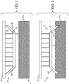
- Fig. 1 and Fig. 2 two different 3D objects (3) have been illustrated, wherein the former one has at least one fluid-collecting, basin-like, open region (8) whereas the latter one has at least one fluid-sucking, dome-like, open region (9).
- At least one drain channel (10) is included into the fluid-collecting, basin-like, open region (8) in the digital 3D model as shown in Fig. 1 for preventing collection of fluid (5; 5a, 5b) during the generation process and the post-processing process.
- at least one vent channel (11) is included into the fluid-sucking, dome-like, open region (9) in the digital 3D model for preventing suction of fluid (5; 5a,5b) during the generation process and the post-processing process.
- the digital 3D model is displayed to a user on a display (not shown).
- the user can perform the determination step and the inclusion step manually on the display.
- these steps may be performed automatically or semiautomatically through algorithms of the computer-program.
- the user can manually select and input on the display the locations of the inlets (12) and/or outlets (13) of the drain channels (10), respectively, to be included into the digital 3D model.
- the path of the drain channels (10) within the digital 3D object (3) may be manually defined on the display by the user or automatically calculated.
- the lowest point in the fluid-collecting, basin-like, open region (8) of the digital 3D model can be automatically found and set as the location of the inlet (12) of the drain channel (10).
- the user can manually select and input on the display the location of the corresponding outlet (13) of the drain channel (10) to be included into the digital 3D model.
- the outlet (13) for the drain channel (10) can also be automatically found at a location lying lower than the corresponding inlet (12) of the drain channel (10).
- one or more outlets (13) for the drain channels (10) are automatically found based on one or more criteria including that the inclination of the drain channel (10) is maximized and/or the length of the drain channel (10) is minimized such that the drain channel (10) remains entirely within the digital 3D model.
- the user can manually select and input on the display the locations of the inlets (12) and/or outlets (13) of the vent channels (11) respectively to be included into the digital 3D model.
- the path of the vent channels (11) within the digital 3D object (3) may be manually defined on the display by the user or automatically calculated.
- the highest point in the fluid-sucking, dome-like, open region (9) of the digital 3D model can be automatically found and set as the location of the outlet (13) of the vent channel (11).
- the user can manually select and input on the display the location of the corresponding inlet (12) of the vent channel (11) to be included into the digital 3D model.
- the inlet (12) for the vent channel (11) can also be automatically found at a location lying higher than the corresponding outlet (13) of the vent channel (11).
- one or more inlets (12) for the vent channels (11) are automatically found based on one or more criteria including that the inclination of the vent channel (11) is maximized and/or the length of the vent channel (11) is minimized such that the vent channel (11) remains entirely within the digital 3D object (3).
- the drain channels (10) or the vent channels (11) have one or more straight segments and/or one or more curved segments with constant or non-constant cross section.
- the user is allowed to selectively mark on the display of the digital 3D model the restricted surface areas and/or the restricted volumes.
- the surface area and/or the volume are automatically restricted in accordance with predetermined conditions. Such conditions may relate, for instance to the mechanical stability, proper operation or the visual appearance of the 3D object.
- the digital 3D object (3) corresponds to a dental appliance (14).
Landscapes
- Chemical & Material Sciences (AREA)
- Engineering & Computer Science (AREA)
- Materials Engineering (AREA)
- Manufacturing & Machinery (AREA)
- Physics & Mathematics (AREA)
- Mechanical Engineering (AREA)
- Optics & Photonics (AREA)
Claims (13)
- Procédé de génération et de post-traitement d'un objet en 3D (3) au moyen d'un système de fabrication additive (1) comprenant : la génération de l'objet en 3D (3) par un appareil de fabrication additive (2) qui génère l'objet en 3D (3) correspondant à un modèle numérique 3D préparé, fixé à une plate-forme (4) par déplacement progressif vers le haut, à partir d'une résine liquide photodurcissable (5a) dans un bac (6) ; et le post-traitement de l'objet en 3D (3) par au moins un appareil de post-traitement (7) qui effectue au moins une action parmi le lavage, le séchage et le durcissement de l'objet en 3D (3) reçu et maintenu dans l'état fixé à la plate-forme (4) pendant le post-traitement, le procédé étant caractérisé en ce qu'il comprend :une étape de préparation du modèle numérique 3D pardétermination des régions ouvertes (8) de collecte de fluide de type bassin et des régions ouvertes (9) d'aspiration de fluide de type dôme du modèle numérique 3D orienté dans ledit état par rapport à la plate-forme (4), etcomprenant au moins un canal de vidange (10) et au moins un canal d'évent (11) dans la région ouverte (8) de collecte de fluide de type bassin et la région ouverte (9) d'aspiration de fluide de type dôme dans le modèle numérique 3D respectivement pour empêcher la collecte de fluide (5a, 5b) et l'aspiration de fluide (5a, 5b) pendant le processus de génération et le processus de post-traitement.
- Procédé selon la revendication 1, caractérisé en ce qu'il comprend en outre :une étape d'affichage du modèle numérique 3D à l'intention d'un utilisateur sur un écran ; etune étape permettant à l'utilisateur de sélectionner et d'entrer manuellement sur l'écran les emplacements des entrées (12) et/ou des sorties (13) des canaux de vidange (10) et/ou des canaux d'évent (11) respectivement à inclure dans le modèle numérique 3D.
- Procédé selon la revendication 2, caractérisé en ce qu'il comprend en outre :une étape consistant à trouver le point le plus bas dans la région ouverte (8) de collecte de fluide de type bassin du modèle numérique 3D et à définir le point le plus bas comme emplacement de l'entrée (12) du canal de vidange (10) ; etune étape permettant à l'utilisateur de sélectionner et d'entrer manuellement sur l'écran l'emplacement de la sortie correspondante (13) du canal de vidange (10) à inclure dans le modèle numérique 3D, ouune étape consistant à trouver au moins une sortie (13) pour le canal de vidange (10) au niveau d'un emplacement situé plus bas que l'entrée correspondante (12) du canal de vidange (10).
- Procédé selon la revendication 3, caractérisé en ce qu'une ou plusieurs sorties (13) pour le canal de vidange (10) sont trouvées sur la base d'un ou plusieurs critères dont le fait que l'inclinaison du canal de vidange (10) est maximisée et/ou la longueur du canal de vidange (10) est minimisée, le canal de vidange (10) restant entièrement à l'intérieur de l'objet numérique en 3D (3).
- Procédé selon l'une quelconque des revendications 2 à 4, caractérisé en ce qu'il comprend en outre :une étape consistant à trouver le point le plus élevé dans la région ouverte (9) d'aspiration de fluide de type dôme du modèle numérique 3D et à définir le point le plus élevé comme emplacement de la sortie (13) du canal d'évent (11) ; etune étape permettant à l'utilisateur de sélectionner et d'entrer manuellement sur l'écran l'emplacement de l'entrée correspondante (12) du canal d'évent (11) à inclure dans le modèle numérique 3D, ouune étape consistant à trouver au moins une entrée (12) pour le canal d'évent (11) au niveau d'un emplacement situé plus haut que la sortie correspondante (13) du canal d'évent (11).
- Procédé selon la revendication 5, caractérisé en ce qu'une ou plusieurs entrées (12) pour le canal d'évent (11) sont trouvées sur la base d'un ou plusieurs critères dont le fait que l'inclinaison du canal d'évent (11) est maximisée et/ou la longueur du canal d'évent (11) est minimisée, le canal d'évent (11) restant entièrement à l'intérieur de l'objet numérique en 3D (3).
- Procédé selon l'une quelconque des revendications 2 à 6, caractérisé en ce qu'il comprend :
une étape de restriction des surfaces du modèle numérique 3D où les emplacements des entrées (12) et/ou des sorties (13) des canaux de vidange (10) et/ou des canaux d'évent (11) peuvent se trouver, et/ou de restriction du volume du modèle numérique 3D où les canaux de vidange (10) et/ou les canaux d'évent (11) peuvent passer, les points les plus bas/les plus hauts étant trouvés en tenant compte de la restriction. - Procédé selon l'une quelconque des revendications 2 à 6, caractérisé en ce qu'il comprend :
une étape de restriction des surfaces du modèle numérique 3D où les emplacements des entrées (12) et/ou des sorties (13) des canaux de vidange (10) et/ou des canaux d'évent (11) ne doivent pas se trouver, et/ou de restriction du volume du modèle numérique 3D où les canaux de vidange (10) et/ou les canaux d'évent (11) ne doivent pas passer, les points les plus bas/les plus hauts étant trouvés en tenant compte de la restriction. - Procédé selon la revendication 7 ou 8, caractérisé en ce qu'il comprend
une étape permettant à l'utilisateur de repérer sélectivement sur l'écran du modèle numérique 3D les surfaces restreintes et/ou les volumes restreints. - Procédé selon l'une quelconque des revendications 1 à 9, caractérisé en ce que les canaux de vidange (10) ou les canaux d'évent (11) ont un ou plusieurs segments rectilignes ou un ou plusieurs segments curvilignes, les segments rectilignes ou curvilignes ayant une section transversale constante ou non constante.
- Procédé selon l'une quelconque des revendications 1 à 11, caractérisé en ce que l'objet numérique en 3D (3) correspond à un appareil dentaire (14).
- Programme informatique comprenant des codes pour amener le système de fabrication additive (1) à exécuter le procédé selon l'une quelconque des revendications 1 à 11.
- Moyen de stockage lisible par ordinateur comprenant le programme informatique selon la revendication 12.
Priority Applications (9)
| Application Number | Priority Date | Filing Date | Title |
|---|---|---|---|
| EP19020275.4A EP3722074B1 (fr) | 2019-04-09 | 2019-04-09 | Procédé de prévention de collecte / d'aspiration de fluide dans une fabrication additive d'objets en 3d |
| BR112021011734-2A BR112021011734B1 (pt) | 2019-04-09 | 2020-04-08 | Método para gerar e pós-processar um objeto 3d, e meio de armazenamento legível por computador |
| KR1020217027986A KR20210148094A (ko) | 2019-04-09 | 2020-04-08 | 3d 물체들의 부가적 제조에서 유체 수집/흡입을 방지하는 방법 |
| PCT/EP2020/059993 WO2020208064A1 (fr) | 2019-04-09 | 2020-04-08 | Procédé d'empêchement de collecte/aspiration de fluide dans la fabrication additive d'objets 3d |
| AU2020271620A AU2020271620B2 (en) | 2019-04-09 | 2020-04-08 | Method of preventing fluid collection / suction in additive manufacturing of 3D objects |
| JP2021546338A JP7536775B2 (ja) | 2019-04-09 | 2020-04-08 | 3d物体の積層造形における流体の貯留/吸引を防止する方法 |
| CN202080010560.9A CN113316511B (zh) | 2019-04-09 | 2020-04-08 | 在3d物体的增材制造中防止流体积聚/吸取的方法 |
| US17/442,681 US20220161500A1 (en) | 2019-04-09 | 2020-04-08 | Method of preventing fluid collection / suction in additive manufacturing of 3d objects |
| CA3125018A CA3125018A1 (fr) | 2019-04-09 | 2020-04-08 | Procede d'empechement de collecte/aspiration de fluide dans la fabrication additive d'objets 3d |
Applications Claiming Priority (1)
| Application Number | Priority Date | Filing Date | Title |
|---|---|---|---|
| EP19020275.4A EP3722074B1 (fr) | 2019-04-09 | 2019-04-09 | Procédé de prévention de collecte / d'aspiration de fluide dans une fabrication additive d'objets en 3d |
Publications (2)
| Publication Number | Publication Date |
|---|---|
| EP3722074A1 EP3722074A1 (fr) | 2020-10-14 |
| EP3722074B1 true EP3722074B1 (fr) | 2022-06-08 |
Family
ID=66175122
Family Applications (1)
| Application Number | Title | Priority Date | Filing Date |
|---|---|---|---|
| EP19020275.4A Active EP3722074B1 (fr) | 2019-04-09 | 2019-04-09 | Procédé de prévention de collecte / d'aspiration de fluide dans une fabrication additive d'objets en 3d |
Country Status (8)
| Country | Link |
|---|---|
| US (1) | US20220161500A1 (fr) |
| EP (1) | EP3722074B1 (fr) |
| JP (1) | JP7536775B2 (fr) |
| KR (1) | KR20210148094A (fr) |
| CN (1) | CN113316511B (fr) |
| AU (1) | AU2020271620B2 (fr) |
| CA (1) | CA3125018A1 (fr) |
| WO (1) | WO2020208064A1 (fr) |
Families Citing this family (1)
| Publication number | Priority date | Publication date | Assignee | Title |
|---|---|---|---|---|
| US20240198588A1 (en) * | 2022-12-16 | 2024-06-20 | Sprintray, Inc. | Hydraulic 3d-printing system and method |
Family Cites Families (17)
| Publication number | Priority date | Publication date | Assignee | Title |
|---|---|---|---|---|
| WO1995029053A2 (fr) * | 1994-04-25 | 1995-11-02 | 3D Systems, Inc. | Techniques de construction ameliorees par stereolithographie |
| US5616293A (en) * | 1995-03-03 | 1997-04-01 | General Motors Corporation | Rapid making of a prototype part or mold using stereolithography model |
| US6856842B2 (en) * | 2002-02-05 | 2005-02-15 | General Electric Company | Method and system for creating a tooling master model for manufacturing parts |
| US8305376B2 (en) * | 2007-04-12 | 2012-11-06 | Dassault Systemes Solidworks Corporation | Locally updating a three-dimensional model |
| US9168112B2 (en) * | 2012-07-27 | 2015-10-27 | Guided Surgery Solutions, Llc | Multi-layer surgical guide |
| WO2014099761A1 (fr) * | 2012-12-17 | 2014-06-26 | Global Filtration Systems, A Dba Of Gulf Filtration Systems Inc. | Modèle d'arcade dentaire et procédé de fabrication associé |
| EP2875934B1 (fr) * | 2013-11-22 | 2017-04-05 | Technische Universität Wien | Dispositif de traitement de matériau photopolymérisable pour le montage en couche d'un corps moulé |
| TWI609769B (zh) * | 2014-06-03 | 2018-01-01 | 三緯國際立體列印科技股份有限公司 | 立體結構與立體列印方法 |
| US10668709B2 (en) * | 2014-08-12 | 2020-06-02 | Carbon, Inc. | Three-dimensional printing using carriers with release mechanisms |
| JP6374271B2 (ja) * | 2014-08-28 | 2018-08-15 | ローランドディー.ジー.株式会社 | 3次元造形装置 |
| US10730241B2 (en) | 2014-11-17 | 2020-08-04 | Autodesk, Inc. | Techniques for automatically placing escape holes during three-dimensional printing |
| WO2016109550A1 (fr) * | 2014-12-31 | 2016-07-07 | Carbon3D, Inc. | Impression en trois dimensions d'objets comprenant des orifices de respiration |
| US11576750B2 (en) * | 2015-07-07 | 2023-02-14 | Align Technology, Inc. | Direct fabrication of aligners for arch expansion |
| IT201700020797A1 (it) * | 2017-02-23 | 2018-08-23 | Dws Srl | Metodo e contenitore per rimuovere residui di resina da un modello realizzato tramite stampa tridimensionale 3D |
| US10766193B2 (en) * | 2017-06-02 | 2020-09-08 | 3D Systems, Inc. | Three dimensional printing system with resin containment solution |
| CN207842053U (zh) | 2017-12-28 | 2018-09-11 | 湖南华曙高科技有限责任公司 | 用于光固化成型的树脂排出装置 |
| CN108245432B (zh) * | 2018-02-09 | 2021-05-14 | 嘉兴学院 | 一种全瓷口腔修复体的增材制造方法 |
-
2019
- 2019-04-09 EP EP19020275.4A patent/EP3722074B1/fr active Active
-
2020
- 2020-04-08 KR KR1020217027986A patent/KR20210148094A/ko not_active Ceased
- 2020-04-08 US US17/442,681 patent/US20220161500A1/en active Pending
- 2020-04-08 CN CN202080010560.9A patent/CN113316511B/zh active Active
- 2020-04-08 CA CA3125018A patent/CA3125018A1/fr active Pending
- 2020-04-08 WO PCT/EP2020/059993 patent/WO2020208064A1/fr not_active Ceased
- 2020-04-08 JP JP2021546338A patent/JP7536775B2/ja active Active
- 2020-04-08 AU AU2020271620A patent/AU2020271620B2/en active Active
Also Published As
| Publication number | Publication date |
|---|---|
| CN113316511B (zh) | 2023-12-08 |
| US20220161500A1 (en) | 2022-05-26 |
| CA3125018A1 (fr) | 2020-10-15 |
| BR112021011734A2 (pt) | 2021-11-09 |
| CN113316511A (zh) | 2021-08-27 |
| KR20210148094A (ko) | 2021-12-07 |
| JP7536775B2 (ja) | 2024-08-20 |
| EP3722074A1 (fr) | 2020-10-14 |
| AU2020271620B2 (en) | 2025-05-15 |
| JP2022527430A (ja) | 2022-06-02 |
| WO2020208064A1 (fr) | 2020-10-15 |
| AU2020271620A1 (en) | 2021-07-01 |
Similar Documents
| Publication | Publication Date | Title |
|---|---|---|
| CN101653827B (zh) | 制造三维形状物品的方法和装置及三维形状物品 | |
| JP2006111013A (ja) | 改良型ステレオリソグラフィー装置 | |
| US5316700A (en) | Method and apparatus for removing excess lens forming material | |
| AU2020271620B2 (en) | Method of preventing fluid collection / suction in additive manufacturing of 3D objects | |
| EP3585591B1 (fr) | Procédé et récipient pour éliminer des résidus de résine d'un modèle créé par impression 3d tridimensionnelle | |
| JP7193585B2 (ja) | 造形物の製造方法及び造形装置 | |
| CN100534770C (zh) | 用于模制塑料透镜的方法 | |
| HK1255293A1 (zh) | 具有倾斜箱的立体平版印刷机 | |
| US20190375152A1 (en) | System for producing an object by means of additive manufacturing | |
| KR20220075415A (ko) | 황동, 청동, 마그네슘, 알루미늄 합금, 및 경합금 등으로 제조된 제품의 반응고 상태에서 다이 캐스팅을 위한 장치 및 방법 | |
| CN105383734B (zh) | 成形灌装机和用于成型并灌装容器的方法 | |
| KR20200010663A (ko) | 폭발방지구조를 가지는 마그네슘분말 3d프린터용 적층시스템 | |
| JP2006082421A (ja) | 光学素子の製造方法および製造装置 | |
| RU2810502C2 (ru) | Способ предотвращения накопления/всасывания текучей среды при аддитивном производстве 3d-объектов | |
| KR20180037547A (ko) | 신발창 성형용 금형 | |
| BR112021011734B1 (pt) | Método para gerar e pós-processar um objeto 3d, e meio de armazenamento legível por computador | |
| KR101671646B1 (ko) | 캐비티 팽창을 이용하는 진공주형 장치 | |
| CN112654488A (zh) | 配备有树脂胶囊的立体光刻设备以及操作所述设备的方法 | |
| FI128627B (en) | Stereolithography equipment provided with resin collection mechanism and method for operating said equipment | |
| WO2023205716A1 (fr) | Moules dentaires creux configurés pour un nettoyage à haut débit | |
| IT202200026292A1 (it) | Apparecchiatura e procedimento per la fusione e lo stampaggio allo stato semi-solido di oggetti in metallo | |
| US7682532B2 (en) | Process of dosing a starting material for optical lenses | |
| RU2021119706A (ru) | Способ предотвращения накопления/всасывания текучей среды при аддитивном производстве 3d-объектов | |
| KR101769680B1 (ko) | 멀티 토출구를 가진 진공주형 장치 | |
| JP2000052436A (ja) | 光造形装置の造形液面調整方法及びそれを使用した造形 液面調整装置 |
Legal Events
| Date | Code | Title | Description |
|---|---|---|---|
| PUAI | Public reference made under article 153(3) epc to a published international application that has entered the european phase |
Free format text: ORIGINAL CODE: 0009012 |
|
| STAA | Information on the status of an ep patent application or granted ep patent |
Free format text: STATUS: THE APPLICATION HAS BEEN PUBLISHED |
|
| AK | Designated contracting states |
Kind code of ref document: A1 Designated state(s): AL AT BE BG CH CY CZ DE DK EE ES FI FR GB GR HR HU IE IS IT LI LT LU LV MC MK MT NL NO PL PT RO RS SE SI SK SM TR |
|
| AX | Request for extension of the european patent |
Extension state: BA ME |
|
| STAA | Information on the status of an ep patent application or granted ep patent |
Free format text: STATUS: REQUEST FOR EXAMINATION WAS MADE |
|
| 17P | Request for examination filed |
Effective date: 20210413 |
|
| RBV | Designated contracting states (corrected) |
Designated state(s): AL AT BE BG CH CY CZ DE DK EE ES FI FR GB GR HR HU IE IS IT LI LT LU LV MC MK MT NL NO PL PT RO RS SE SI SK SM TR |
|
| GRAP | Despatch of communication of intention to grant a patent |
Free format text: ORIGINAL CODE: EPIDOSNIGR1 |
|
| STAA | Information on the status of an ep patent application or granted ep patent |
Free format text: STATUS: GRANT OF PATENT IS INTENDED |
|
| RIC1 | Information provided on ipc code assigned before grant |
Ipc: B33Y 50/00 20150101ALI20211217BHEP Ipc: B33Y 40/20 20200101ALI20211217BHEP Ipc: B33Y 10/00 20150101ALI20211217BHEP Ipc: B29C 64/386 20170101ALI20211217BHEP Ipc: B29C 64/35 20170101ALI20211217BHEP Ipc: B29C 64/124 20170101AFI20211217BHEP |
|
| INTG | Intention to grant announced |
Effective date: 20220114 |
|
| GRAS | Grant fee paid |
Free format text: ORIGINAL CODE: EPIDOSNIGR3 |
|
| GRAA | (expected) grant |
Free format text: ORIGINAL CODE: 0009210 |
|
| STAA | Information on the status of an ep patent application or granted ep patent |
Free format text: STATUS: THE PATENT HAS BEEN GRANTED |
|
| AK | Designated contracting states |
Kind code of ref document: B1 Designated state(s): AL AT BE BG CH CY CZ DE DK EE ES FI FR GB GR HR HU IE IS IT LI LT LU LV MC MK MT NL NO PL PT RO RS SE SI SK SM TR |
|
| REG | Reference to a national code |
Ref country code: AT Ref legal event code: REF Ref document number: 1496635 Country of ref document: AT Kind code of ref document: T Effective date: 20220615 Ref country code: CH Ref legal event code: EP |
|
| REG | Reference to a national code |
Ref country code: DE Ref legal event code: R096 Ref document number: 602019015527 Country of ref document: DE |
|
| REG | Reference to a national code |
Ref country code: IE Ref legal event code: FG4D |
|
| REG | Reference to a national code |
Ref country code: LT Ref legal event code: MG9D |
|
| REG | Reference to a national code |
Ref country code: NL Ref legal event code: MP Effective date: 20220608 |
|
| PG25 | Lapsed in a contracting state [announced via postgrant information from national office to epo] |
Ref country code: SE Free format text: LAPSE BECAUSE OF FAILURE TO SUBMIT A TRANSLATION OF THE DESCRIPTION OR TO PAY THE FEE WITHIN THE PRESCRIBED TIME-LIMIT Effective date: 20220608 Ref country code: NO Free format text: LAPSE BECAUSE OF FAILURE TO SUBMIT A TRANSLATION OF THE DESCRIPTION OR TO PAY THE FEE WITHIN THE PRESCRIBED TIME-LIMIT Effective date: 20220908 Ref country code: LT Free format text: LAPSE BECAUSE OF FAILURE TO SUBMIT A TRANSLATION OF THE DESCRIPTION OR TO PAY THE FEE WITHIN THE PRESCRIBED TIME-LIMIT Effective date: 20220608 Ref country code: HR Free format text: LAPSE BECAUSE OF FAILURE TO SUBMIT A TRANSLATION OF THE DESCRIPTION OR TO PAY THE FEE WITHIN THE PRESCRIBED TIME-LIMIT Effective date: 20220608 Ref country code: GR Free format text: LAPSE BECAUSE OF FAILURE TO SUBMIT A TRANSLATION OF THE DESCRIPTION OR TO PAY THE FEE WITHIN THE PRESCRIBED TIME-LIMIT Effective date: 20220909 Ref country code: FI Free format text: LAPSE BECAUSE OF FAILURE TO SUBMIT A TRANSLATION OF THE DESCRIPTION OR TO PAY THE FEE WITHIN THE PRESCRIBED TIME-LIMIT Effective date: 20220608 Ref country code: ES Free format text: LAPSE BECAUSE OF FAILURE TO SUBMIT A TRANSLATION OF THE DESCRIPTION OR TO PAY THE FEE WITHIN THE PRESCRIBED TIME-LIMIT Effective date: 20220608 Ref country code: BG Free format text: LAPSE BECAUSE OF FAILURE TO SUBMIT A TRANSLATION OF THE DESCRIPTION OR TO PAY THE FEE WITHIN THE PRESCRIBED TIME-LIMIT Effective date: 20220908 |
|
| PG25 | Lapsed in a contracting state [announced via postgrant information from national office to epo] |
Ref country code: RS Free format text: LAPSE BECAUSE OF FAILURE TO SUBMIT A TRANSLATION OF THE DESCRIPTION OR TO PAY THE FEE WITHIN THE PRESCRIBED TIME-LIMIT Effective date: 20220608 Ref country code: LV Free format text: LAPSE BECAUSE OF FAILURE TO SUBMIT A TRANSLATION OF THE DESCRIPTION OR TO PAY THE FEE WITHIN THE PRESCRIBED TIME-LIMIT Effective date: 20220608 |
|
| PG25 | Lapsed in a contracting state [announced via postgrant information from national office to epo] |
Ref country code: NL Free format text: LAPSE BECAUSE OF FAILURE TO SUBMIT A TRANSLATION OF THE DESCRIPTION OR TO PAY THE FEE WITHIN THE PRESCRIBED TIME-LIMIT Effective date: 20220608 |
|
| PG25 | Lapsed in a contracting state [announced via postgrant information from national office to epo] |
Ref country code: SM Free format text: LAPSE BECAUSE OF FAILURE TO SUBMIT A TRANSLATION OF THE DESCRIPTION OR TO PAY THE FEE WITHIN THE PRESCRIBED TIME-LIMIT Effective date: 20220608 Ref country code: SK Free format text: LAPSE BECAUSE OF FAILURE TO SUBMIT A TRANSLATION OF THE DESCRIPTION OR TO PAY THE FEE WITHIN THE PRESCRIBED TIME-LIMIT Effective date: 20220608 Ref country code: RO Free format text: LAPSE BECAUSE OF FAILURE TO SUBMIT A TRANSLATION OF THE DESCRIPTION OR TO PAY THE FEE WITHIN THE PRESCRIBED TIME-LIMIT Effective date: 20220608 Ref country code: PT Free format text: LAPSE BECAUSE OF FAILURE TO SUBMIT A TRANSLATION OF THE DESCRIPTION OR TO PAY THE FEE WITHIN THE PRESCRIBED TIME-LIMIT Effective date: 20221010 Ref country code: EE Free format text: LAPSE BECAUSE OF FAILURE TO SUBMIT A TRANSLATION OF THE DESCRIPTION OR TO PAY THE FEE WITHIN THE PRESCRIBED TIME-LIMIT Effective date: 20220608 Ref country code: CZ Free format text: LAPSE BECAUSE OF FAILURE TO SUBMIT A TRANSLATION OF THE DESCRIPTION OR TO PAY THE FEE WITHIN THE PRESCRIBED TIME-LIMIT Effective date: 20220608 |
|
| PG25 | Lapsed in a contracting state [announced via postgrant information from national office to epo] |
Ref country code: PL Free format text: LAPSE BECAUSE OF FAILURE TO SUBMIT A TRANSLATION OF THE DESCRIPTION OR TO PAY THE FEE WITHIN THE PRESCRIBED TIME-LIMIT Effective date: 20220608 Ref country code: IS Free format text: LAPSE BECAUSE OF FAILURE TO SUBMIT A TRANSLATION OF THE DESCRIPTION OR TO PAY THE FEE WITHIN THE PRESCRIBED TIME-LIMIT Effective date: 20221008 |
|
| REG | Reference to a national code |
Ref country code: DE Ref legal event code: R097 Ref document number: 602019015527 Country of ref document: DE |
|
| PG25 | Lapsed in a contracting state [announced via postgrant information from national office to epo] |
Ref country code: AL Free format text: LAPSE BECAUSE OF FAILURE TO SUBMIT A TRANSLATION OF THE DESCRIPTION OR TO PAY THE FEE WITHIN THE PRESCRIBED TIME-LIMIT Effective date: 20220608 |
|
| PLBE | No opposition filed within time limit |
Free format text: ORIGINAL CODE: 0009261 |
|
| STAA | Information on the status of an ep patent application or granted ep patent |
Free format text: STATUS: NO OPPOSITION FILED WITHIN TIME LIMIT |
|
| PG25 | Lapsed in a contracting state [announced via postgrant information from national office to epo] |
Ref country code: DK Free format text: LAPSE BECAUSE OF FAILURE TO SUBMIT A TRANSLATION OF THE DESCRIPTION OR TO PAY THE FEE WITHIN THE PRESCRIBED TIME-LIMIT Effective date: 20220608 |
|
| 26N | No opposition filed |
Effective date: 20230310 |
|
| PG25 | Lapsed in a contracting state [announced via postgrant information from national office to epo] |
Ref country code: SI Free format text: LAPSE BECAUSE OF FAILURE TO SUBMIT A TRANSLATION OF THE DESCRIPTION OR TO PAY THE FEE WITHIN THE PRESCRIBED TIME-LIMIT Effective date: 20220608 |
|
| PG25 | Lapsed in a contracting state [announced via postgrant information from national office to epo] |
Ref country code: LU Free format text: LAPSE BECAUSE OF NON-PAYMENT OF DUE FEES Effective date: 20230409 |
|
| REG | Reference to a national code |
Ref country code: BE Ref legal event code: MM Effective date: 20230430 |
|
| PG25 | Lapsed in a contracting state [announced via postgrant information from national office to epo] |
Ref country code: MC Free format text: LAPSE BECAUSE OF FAILURE TO SUBMIT A TRANSLATION OF THE DESCRIPTION OR TO PAY THE FEE WITHIN THE PRESCRIBED TIME-LIMIT Effective date: 20220608 |
|
| PG25 | Lapsed in a contracting state [announced via postgrant information from national office to epo] |
Ref country code: MC Free format text: LAPSE BECAUSE OF FAILURE TO SUBMIT A TRANSLATION OF THE DESCRIPTION OR TO PAY THE FEE WITHIN THE PRESCRIBED TIME-LIMIT Effective date: 20220608 |
|
| REG | Reference to a national code |
Ref country code: IE Ref legal event code: MM4A |
|
| REG | Reference to a national code |
Ref country code: AT Ref legal event code: UEP Ref document number: 1496635 Country of ref document: AT Kind code of ref document: T Effective date: 20220608 |
|
| PG25 | Lapsed in a contracting state [announced via postgrant information from national office to epo] |
Ref country code: BE Free format text: LAPSE BECAUSE OF NON-PAYMENT OF DUE FEES Effective date: 20230430 |
|
| PG25 | Lapsed in a contracting state [announced via postgrant information from national office to epo] |
Ref country code: IE Free format text: LAPSE BECAUSE OF NON-PAYMENT OF DUE FEES Effective date: 20230409 |
|
| PG25 | Lapsed in a contracting state [announced via postgrant information from national office to epo] |
Ref country code: IE Free format text: LAPSE BECAUSE OF NON-PAYMENT OF DUE FEES Effective date: 20230409 |
|
| P01 | Opt-out of the competence of the unified patent court (upc) registered |
Free format text: CASE NUMBER: UPC_APP_413124/2023 Effective date: 20230509 |
|
| PG25 | Lapsed in a contracting state [announced via postgrant information from national office to epo] |
Ref country code: BG Free format text: LAPSE BECAUSE OF FAILURE TO SUBMIT A TRANSLATION OF THE DESCRIPTION OR TO PAY THE FEE WITHIN THE PRESCRIBED TIME-LIMIT Effective date: 20220608 |
|
| PG25 | Lapsed in a contracting state [announced via postgrant information from national office to epo] |
Ref country code: BG Free format text: LAPSE BECAUSE OF FAILURE TO SUBMIT A TRANSLATION OF THE DESCRIPTION OR TO PAY THE FEE WITHIN THE PRESCRIBED TIME-LIMIT Effective date: 20220608 |
|
| PGFP | Annual fee paid to national office [announced via postgrant information from national office to epo] |
Ref country code: DE Payment date: 20250319 Year of fee payment: 7 |
|
| PGFP | Annual fee paid to national office [announced via postgrant information from national office to epo] |
Ref country code: CH Payment date: 20250501 Year of fee payment: 7 |
|
| PGFP | Annual fee paid to national office [announced via postgrant information from national office to epo] |
Ref country code: AT Payment date: 20250321 Year of fee payment: 7 |
|
| PG25 | Lapsed in a contracting state [announced via postgrant information from national office to epo] |
Ref country code: CY Free format text: LAPSE BECAUSE OF FAILURE TO SUBMIT A TRANSLATION OF THE DESCRIPTION OR TO PAY THE FEE WITHIN THE PRESCRIBED TIME-LIMIT; INVALID AB INITIO Effective date: 20190409 |
|
| PG25 | Lapsed in a contracting state [announced via postgrant information from national office to epo] |
Ref country code: HU Free format text: LAPSE BECAUSE OF FAILURE TO SUBMIT A TRANSLATION OF THE DESCRIPTION OR TO PAY THE FEE WITHIN THE PRESCRIBED TIME-LIMIT; INVALID AB INITIO Effective date: 20190409 |
|
| PG25 | Lapsed in a contracting state [announced via postgrant information from national office to epo] |
Ref country code: TR Free format text: LAPSE BECAUSE OF FAILURE TO SUBMIT A TRANSLATION OF THE DESCRIPTION OR TO PAY THE FEE WITHIN THE PRESCRIBED TIME-LIMIT Effective date: 20220608 |
|
| PGFP | Annual fee paid to national office [announced via postgrant information from national office to epo] |
Ref country code: GB Payment date: 20260319 Year of fee payment: 8 |
|
| PGFP | Annual fee paid to national office [announced via postgrant information from national office to epo] |
Ref country code: IT Payment date: 20260319 Year of fee payment: 8 |
|
| PGFP | Annual fee paid to national office [announced via postgrant information from national office to epo] |
Ref country code: FR Payment date: 20260320 Year of fee payment: 8 |
|
| REG | Reference to a national code |
Ref country code: CH Ref legal event code: U11 Free format text: ST27 STATUS EVENT CODE: U-0-0-U10-U11 (AS PROVIDED BY THE NATIONAL OFFICE) Effective date: 20260501 |