EP3722191A1 - Deux roues convertibles - Google Patents
Deux roues convertibles Download PDFInfo
- Publication number
- EP3722191A1 EP3722191A1 EP20020160.6A EP20020160A EP3722191A1 EP 3722191 A1 EP3722191 A1 EP 3722191A1 EP 20020160 A EP20020160 A EP 20020160A EP 3722191 A1 EP3722191 A1 EP 3722191A1
- Authority
- EP
- European Patent Office
- Prior art keywords
- frame
- fastening element
- convertible
- rod
- receptacles
- Prior art date
- Legal status (The legal status is an assumption and is not a legal conclusion. Google has not performed a legal analysis and makes no representation as to the accuracy of the status listed.)
- Withdrawn
Links
Images


Classifications
-
- B—PERFORMING OPERATIONS; TRANSPORTING
- B62—LAND VEHICLES FOR TRAVELLING OTHERWISE THAN ON RAILS
- B62K—CYCLES; CYCLE FRAMES; CYCLE STEERING DEVICES; RIDER-OPERATED TERMINAL CONTROLS SPECIALLY ADAPTED FOR CYCLES; CYCLE AXLE SUSPENSIONS; CYCLE SIDECARS, FORECARS, OR THE LIKE
- B62K13/00—Cycles convertible to, or transformable into, other types of cycles or land vehicle
- B62K13/08—Frames
-
- B—PERFORMING OPERATIONS; TRANSPORTING
- B62—LAND VEHICLES FOR TRAVELLING OTHERWISE THAN ON RAILS
- B62K—CYCLES; CYCLE FRAMES; CYCLE STEERING DEVICES; RIDER-OPERATED TERMINAL CONTROLS SPECIALLY ADAPTED FOR CYCLES; CYCLE AXLE SUSPENSIONS; CYCLE SIDECARS, FORECARS, OR THE LIKE
- B62K13/00—Cycles convertible to, or transformable into, other types of cycles or land vehicle
-
- B—PERFORMING OPERATIONS; TRANSPORTING
- B62—LAND VEHICLES FOR TRAVELLING OTHERWISE THAN ON RAILS
- B62K—CYCLES; CYCLE FRAMES; CYCLE STEERING DEVICES; RIDER-OPERATED TERMINAL CONTROLS SPECIALLY ADAPTED FOR CYCLES; CYCLE AXLE SUSPENSIONS; CYCLE SIDECARS, FORECARS, OR THE LIKE
- B62K19/00—Cycle frames
- B62K19/30—Frame parts shaped to receive other cycle parts or accessories
- B62K19/34—Bottom brackets
-
- B—PERFORMING OPERATIONS; TRANSPORTING
- B62—LAND VEHICLES FOR TRAVELLING OTHERWISE THAN ON RAILS
- B62M—RIDER PROPULSION OF WHEELED VEHICLES OR SLEDGES; POWERED PROPULSION OF SLEDGES OR SINGLE-TRACK CYCLES; TRANSMISSIONS SPECIALLY ADAPTED FOR SUCH VEHICLES
- B62M3/00—Construction of cranks operated by hand or foot
-
- B—PERFORMING OPERATIONS; TRANSPORTING
- B62—LAND VEHICLES FOR TRAVELLING OTHERWISE THAN ON RAILS
- B62M—RIDER PROPULSION OF WHEELED VEHICLES OR SLEDGES; POWERED PROPULSION OF SLEDGES OR SINGLE-TRACK CYCLES; TRANSMISSIONS SPECIALLY ADAPTED FOR SUCH VEHICLES
- B62M3/00—Construction of cranks operated by hand or foot
- B62M3/16—Accessories
Definitions
- the invention relates to a convertible two-wheeler according to the preamble of claim 1.
- the GB 598 235 A shows a convertible two-wheeled vehicle with a frame, two wheels rotatably mounted on the frame, one of which can be steered with a handlebar.
- Two receptacles are attached to the frame, as well as a pedal crank unit which has a fastening element that can be positively connected to the two receptacles on the frame.
- Both receptacles have the shape of a cylindrical rod which are held at a distance from the frame by webs.
- the fastening element has a recess which is adapted to the shape of the cylindrical rod.
- a bottom bracket for pedal cranks is attached to the fastening element.
- FIG. 3 shows a convertible bicycle with a detachable crank unit attached to the frame via two receptacles.
- a first receptacle is attached in a horizontal area of the frame and a second receptacle is attached to a vertically inclined area of the frame.
- Convertible bikes with removable crank units are also from the U.S. 1 907 645 A , FR 533 655 A , US 2018 0 050 760 A1 and US 2014 0 084 564 A1 known.
- the DE 32 444 661 A1 describes a convertible two-wheeler that can be used as a scooter, balance bike or bicycle.
- a scooter with two wheels rotatably mounted on a frame and a handlebar
- a height-adjustable and swiveling saddle By adjusting the height of the handlebars, a running bike of the type of a draisine can be created and a bicycle can be realized by adding a pedal crank drive.
- the attachment and removal of the relevant parts requires the use of tools.
- the object of the invention is to improve the convertible two-wheeler mentioned at the beginning in such a way that it can be converted in a simple manner, quickly and in particular without tools, without any prior knowledge.
- the basic idea of the invention is to attach a pedal crank unit by simply hanging it on the frame of the two-wheeler. If a drive chain or a drive belt is attached, a bicycle can be turned into a bicycle in a few simple steps.
- crank unit which has a fastening element which can be connected in a form-fitting manner to the two receptacles on the frame.
- the crank unit contains the usual cranks, which are connected to one another by means of a shaft, as well as a drive wheel, which can be a sprocket wheel or a belt pulley, and the fastening element mentioned, which can be inserted into the receptacles mentioned.
- one of the receptacles is on a horizontal area of the frame and the other receptacle is vertical on one inclined area of the frame attached so that horizontally and vertically acting forces of the crank unit are directed into the frame.
- both receptacles have the shape of a rod which is held at a distance from the frame by webs.
- the fastening element can be held stably between the rods and the frame.
- At least one receptacle is an opening in the frame into which the fastening element can be hooked.
- the fastening element is designed in the region of one end so that it can be attached to the frame. This can be done by means of the mentioned opening in the frame or also on the mentioned rod. In the latter case, the fastening element has a recess in the region of one end, the shape of which is adapted to the rod. The recess is such that the fastening element can be hung on the rod and pivoted there. In the opposite area of the fastening element, a recess is provided which is dimensioned such that it can receive the rod of the other receptacle. In this recess, a displaceable bolt is provided which can be pushed between the frame and the rod in order to lock the fastening element on the frame. This latch can also be biased into a closed position by a spring.
- the receptacles on the frame are arranged in such a way that after the fastening element has been hooked into the first hanging point, the fastening element is pivoted so that the distance between the Drive wheel crank unit enlarged to the driven wheel so that a drive chain or toothed belt is tensioned.
- the bolt preferably has a run-on bevel in order to ensure better and easier tensioning of the fastening element.
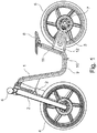
- Figure 1 shows initially essentially a conventional wheel with a frame 1, a front fork 2, a rear swing arm 3, a front wheel 4 and a rear wheel 5.
- the wheel also has the usual handlebar 6, brake disks 7 and a saddle 8.
- a front receptacle 10 is provided on the lower horizontal region 9 of the frame 1 and a second receptacle 12 is provided on the rear, somewhat vertically inclined region 11 of the frame 1, the latter in FIG Fig 1 is not shown because it is covered by the rear swing arm 3 in the figure.
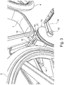
- the second receptacle 12 is in Fig. 3 to see.
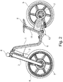
- Fig. 2 shows that a pedal crank unit 13 is attached to these two receptacles 10 and 12 when the wheel is redesigned into a bicycle.
- a drive chain or a drive belt must also be placed between the pedal crank unit 13 and the driven rear wheel 5.
- only one rear wheel swing arm 3 is provided, specifically on the side facing away from the pedal crank unit 13. The pedal crank unit 13 together with the drive chain or drive belt can thus be attached particularly easily.
- FIG 3 illustrates the mounting of the crank unit 13 on the frame 1.
- the crank unit 13 contains the usual cranks 14 and 15 which are attached to a common shaft 16. It also has a drive wheel 17 which is connected to the shaft 16 in a rotationally fixed manner. Finally, a fastening element 19 is connected to the shaft 16 in such a way that it can be pivoted on the shaft 16.
- the fastening element 19 also contains, as will be explained below, the usual pedal bearings of a bicycle drive.
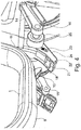
- the fastening element 19 is pushed between the rear vertical region 11 of the frame 1 and the rod 12 so that the recess 20 overlaps the rod 12. Subsequently, the fastening element 19 can be pivoted together with the entire crank unit 13 about the axis of the rod 12, so that the other end of the fastening element approaches the front receptacle 10, as in FIG Figure 4 shown.
- the fastening element is already hung with its recess 20 in the second rod 12 and pivoted in the direction of the front wheel 4.
- the fastening element 19 has a recess 21 which is so large that it can receive the front rod 10 completely.
- the side of the fastening element 19 facing the frame 1 is adapted to the shape of the frame, so that the fastening element 19 clings to the contour of the underside of the frame.
- Adjacent to the recess 21 is a displaceable bolt 22 which can engage in the gap between the rod 10 of the front receptacle and the underside of the frame 1 in order to fix the fastening element 19 on the frame 1.
- lateral projections 23 are provided which protrude through an opening 23 in the side wall and are thus accessible from the outside.
- the crank unit 13 is pivoted together with the fastening elements 19 around the axis of the second rod 12 until the fastening element 19 rests against the frame 1 and the front receptacle 10 comes to rest completely in the recess 21.
- the bolt 22 is then moved in order to fix the entire unit to the frame 1.
- the bolt 22 has a bevel 25 on its front edge which, when fastened, facilitates sliding on the counter element such as for example on the rod 10 or a part of the frame.
- Figure 5 shows the fastening element 19 again more clearly in the installed state, in which the bolt 22 is advanced so far that it engages over the rod 10. How out Figure 5 As can be seen, a front tip of the bolt 22 is so long that it engages around the rod 10 in the pushed-in state beyond a vertical center line, so that an involuntary loosening of the bolt 22 is prevented. An elastic bracing of the bolt 22 and the fastening element 19 is given by the material properties of the fastening element 19 and the bolt 22. In addition, the bolt 22 can also be pressed into the closed position by a spring, whereby the closed position is secured.
- the pedal crank unit can be opened so that the pedal bearing 26 can be removed separately.
- the crank unit has the fastening element 19, which is in the same way as in the embodiments of Figures 2-6 can be attached to the frame 1.
- the fastening element 19 consists of two washers which are arranged parallel to one another and are connected to one another by screw bolts 27, 28 and 29.
- the fastening element 19 has an approximately semicircular recess into which the bottom bracket 26 is inserted.
- a second Fastening element 30 also has an approximately semicircular recess for the bottom bracket. It can be hung with hook 31 on the screw bolt 29 and pivoted about its axis.
- a pivot bearing 33 for a tensioning lever 32 is provided at the end of the second fastening element 30 opposite the hook 31.
- a hook 34 is attached to the tensioning lever 32 by means of a pivot bearing 36, which hook can engage in the screw bolt 27.
- the length of this hook 34 is adjustable via a screw thread 35. If the hook 34 is hung in the screw bolt 27 and the tensioning lever 32 is then pivoted in the direction of the second fastening element 30, the two fastening elements 19 and 30 are braced against one another and thus against the bottom bracket 26.
- the bottom bracket 26 is then fixed to the frame 1.
- the arrangement of the screw bolts 27 of the bottom bracket 36 and the pivot bearing 33 relative to one another is designed in such a way that the tensioning lever 32 assumes a so-called over-center position in the closed position, so that the entire unit is also firmly locked.
Landscapes
- Engineering & Computer Science (AREA)
- Mechanical Engineering (AREA)
- Chemical & Material Sciences (AREA)
- Combustion & Propulsion (AREA)
- Transportation (AREA)
- Steering Devices For Bicycles And Motorcycles (AREA)
- Automatic Cycles, And Cycles In General (AREA)
- Fittings On The Vehicle Exterior For Carrying Loads, And Devices For Holding Or Mounting Articles (AREA)
Applications Claiming Priority (1)
| Application Number | Priority Date | Filing Date | Title |
|---|---|---|---|
| DE102019002631.4A DE102019002631B4 (de) | 2019-04-10 | 2019-04-10 | Umwandelbares Zweirad |
Publications (1)
| Publication Number | Publication Date |
|---|---|
| EP3722191A1 true EP3722191A1 (fr) | 2020-10-14 |
Family
ID=70285373
Family Applications (1)
| Application Number | Title | Priority Date | Filing Date |
|---|---|---|---|
| EP20020160.6A Withdrawn EP3722191A1 (fr) | 2019-04-10 | 2020-04-08 | Deux roues convertibles |
Country Status (4)
| Country | Link |
|---|---|
| US (1) | US20200324847A1 (fr) |
| EP (1) | EP3722191A1 (fr) |
| CN (2) | CN111422293B (fr) |
| DE (1) | DE102019002631B4 (fr) |
Families Citing this family (1)
| Publication number | Priority date | Publication date | Assignee | Title |
|---|---|---|---|---|
| DE102019002631B4 (de) * | 2019-04-10 | 2021-12-23 | Pascher + Heinz GmbH | Umwandelbares Zweirad |
Citations (9)
| Publication number | Priority date | Publication date | Assignee | Title |
|---|---|---|---|---|
| US583022A (en) | 1897-05-25 | Theodore h | ||
| FR533655A (fr) | 1919-03-18 | 1922-03-08 | Bracket suspendu amovible et indéréglable pour vélos et motos | |
| US1907645A (en) | 1931-09-10 | 1933-05-09 | Glaser Amandus | Frame for bicycles or motorcycles |
| GB598235A (en) | 1944-10-21 | 1948-02-13 | Vernon Layton Parry | Improvements in or relating to juvenile cycles |
| DE3244661A1 (de) | 1981-12-16 | 1983-07-21 | Energy Conversion Devices, Inc., 48084 Troy, Mich. | Verfahren zur herstellung einer festphasenlegierung |
| US20140084564A1 (en) | 2012-09-26 | 2014-03-27 | Vulcan Sports Co., Ltd. | Universal Frame for Electric Bikes and Human Powered Bicycles |
| US20180050760A1 (en) | 2016-08-17 | 2018-02-22 | Bruce Ponder | Mid-mount motor assembly apparatus and method of use |
| WO2018217215A1 (fr) * | 2017-05-25 | 2018-11-29 | Strider Sports International, Inc. | Appareil de bicyclette de conversion |
| CN109334845A (zh) * | 2018-12-10 | 2019-02-15 | 雷派的(北京)贸易有限公司 | 一种骑行设备及其转换拆装结构 |
Family Cites Families (9)
| Publication number | Priority date | Publication date | Assignee | Title |
|---|---|---|---|---|
| DE3244466A1 (de) | 1982-12-01 | 1984-06-07 | Klaus Dipl.-Ing. 7500 Karlsruhe Vorhauer | Umwandelbares zweirad |
| DE20009914U1 (de) * | 2000-06-02 | 2001-02-15 | Frohn, Jörg, 50226 Frechen | Stecksystem für Lauf-Fahrrad |
| CN1539698A (zh) * | 2003-04-25 | 2004-10-27 | 赵弘昌 | 可拆解车架的自行车结构 |
| KR20090100873A (ko) * | 2008-03-21 | 2009-09-24 | 이영우 | 페달용 구동력 전달장치 |
| JP2015024686A (ja) * | 2013-07-24 | 2015-02-05 | 株式会社 ビタミンアイファクトリー | 走行練習用自転車 |
| CN104890782A (zh) * | 2014-03-05 | 2015-09-09 | 安恒美有限公司 | 两用童车 |
| CN107140078A (zh) * | 2016-11-24 | 2017-09-08 | 天津富士达自行车有限公司 | 一种滑行和踩踏两用的儿童自行车 |
| CN107128412A (zh) * | 2017-05-12 | 2017-09-05 | 骑记(厦门)科技有限公司 | 一种骑行滑步二合一自行车及其操作方法 |
| DE102019002631B4 (de) * | 2019-04-10 | 2021-12-23 | Pascher + Heinz GmbH | Umwandelbares Zweirad |
-
2019
- 2019-04-10 DE DE102019002631.4A patent/DE102019002631B4/de not_active Expired - Fee Related
- 2019-12-25 CN CN201911359506.0A patent/CN111422293B/zh not_active Expired - Fee Related
- 2019-12-25 CN CN201922366520.5U patent/CN211943619U/zh not_active Expired - Fee Related
-
2020
- 2020-04-08 EP EP20020160.6A patent/EP3722191A1/fr not_active Withdrawn
- 2020-04-10 US US16/845,310 patent/US20200324847A1/en not_active Abandoned
Patent Citations (9)
| Publication number | Priority date | Publication date | Assignee | Title |
|---|---|---|---|---|
| US583022A (en) | 1897-05-25 | Theodore h | ||
| FR533655A (fr) | 1919-03-18 | 1922-03-08 | Bracket suspendu amovible et indéréglable pour vélos et motos | |
| US1907645A (en) | 1931-09-10 | 1933-05-09 | Glaser Amandus | Frame for bicycles or motorcycles |
| GB598235A (en) | 1944-10-21 | 1948-02-13 | Vernon Layton Parry | Improvements in or relating to juvenile cycles |
| DE3244661A1 (de) | 1981-12-16 | 1983-07-21 | Energy Conversion Devices, Inc., 48084 Troy, Mich. | Verfahren zur herstellung einer festphasenlegierung |
| US20140084564A1 (en) | 2012-09-26 | 2014-03-27 | Vulcan Sports Co., Ltd. | Universal Frame for Electric Bikes and Human Powered Bicycles |
| US20180050760A1 (en) | 2016-08-17 | 2018-02-22 | Bruce Ponder | Mid-mount motor assembly apparatus and method of use |
| WO2018217215A1 (fr) * | 2017-05-25 | 2018-11-29 | Strider Sports International, Inc. | Appareil de bicyclette de conversion |
| CN109334845A (zh) * | 2018-12-10 | 2019-02-15 | 雷派的(北京)贸易有限公司 | 一种骑行设备及其转换拆装结构 |
Also Published As
| Publication number | Publication date |
|---|---|
| US20200324847A1 (en) | 2020-10-15 |
| DE102019002631B4 (de) | 2021-12-23 |
| CN211943619U (zh) | 2020-11-17 |
| CN111422293A (zh) | 2020-07-17 |
| DE102019002631A1 (de) | 2020-10-15 |
| CN111422293B (zh) | 2021-09-17 |
Similar Documents
| Publication | Publication Date | Title |
|---|---|---|
| EP0662419B1 (fr) | Bicyclette avec une fourche avant d'un matériel composite | |
| DE102018128861B4 (de) | Fahrradsattelbefestigungs-Anordnung | |
| DE69806051T2 (de) | Tretlager ohne totpunkte und vorrichtung mit solchem tretlager und messvorrichtung | |
| DE3224589C2 (de) | Gepäckträger für ein Zweirad | |
| DE9303510U1 (de) | Heckträger für Fahrzeuge mit einer Anhängerkupplung | |
| DE102018116195B4 (de) | Gepäckträger-Anordnung mit Adapter | |
| DE3405357C2 (fr) | ||
| EP3722191A1 (fr) | Deux roues convertibles | |
| DE10200568A1 (de) | Ausfallende eines Fahrradrahmens | |
| DE4029012A1 (de) | Fahrrad, abnehmbares bauteil eines fahrrades und zubehoer fuer ein zweirad | |
| DE3421210A1 (de) | Fahrradkettenkasten aus kunststoff | |
| EP0530403B1 (fr) | Porte-bagage pour un véhicule à deux roues, particulièrement une bicyclette | |
| DE19532057C2 (de) | Steckachsenhalterung für Zweiräder | |
| DE69311983T2 (de) | Gerät zur demontierbaren Befestigung eines Kindersitzes und dergleichen über dem Hinterrad eines Fahrrads | |
| DE3137348A1 (de) | Fahrradtraeger zur befestigung auf traegerbruecken von kraftfahrzeugen | |
| DE2621683A1 (de) | Vorrichtung zur befestigung von fahrraedern auf autodachtraegern | |
| DE8813796U1 (de) | Aus Grund- und Aufbauträger zusammengesetzter Fahrzeugdachträger | |
| DE69712576T2 (de) | Lastträger | |
| CH695679A5 (de) | Sattelstützengepräckträger. | |
| DE4039723A1 (de) | Fahrrad- und gepaeckhalter fuer die heckklappe bei fahrzeugen | |
| DE20213549U1 (de) | Rahmenschloß | |
| DE202004018574U1 (de) | Fahrrad-Kotflügel-Anschlussgebilde | |
| DE3151980A1 (de) | "fahrradstuetze" | |
| DE202016003724U1 (de) | Sattelstütze | |
| EP0592786B1 (fr) | Disposition de portes-bagages latéraux pour bicyclette |
Legal Events
| Date | Code | Title | Description |
|---|---|---|---|
| PUAI | Public reference made under article 153(3) epc to a published international application that has entered the european phase |
Free format text: ORIGINAL CODE: 0009012 |
|
| STAA | Information on the status of an ep patent application or granted ep patent |
Free format text: STATUS: THE APPLICATION HAS BEEN PUBLISHED |
|
| AK | Designated contracting states |
Kind code of ref document: A1 Designated state(s): AL AT BE BG CH CY CZ DE DK EE ES FI FR GB GR HR HU IE IS IT LI LT LU LV MC MK MT NL NO PL PT RO RS SE SI SK SM TR |
|
| AX | Request for extension of the european patent |
Extension state: BA ME |
|
| STAA | Information on the status of an ep patent application or granted ep patent |
Free format text: STATUS: THE APPLICATION IS DEEMED TO BE WITHDRAWN |
|
| 18D | Application deemed to be withdrawn |
Effective date: 20210415 |