EP3722193B1 - Transistor torque et vélo électrique pourvu de transistor torque - Google Patents
Transistor torque et vélo électrique pourvu de transistor torque Download PDFInfo
- Publication number
- EP3722193B1 EP3722193B1 EP19168972.8A EP19168972A EP3722193B1 EP 3722193 B1 EP3722193 B1 EP 3722193B1 EP 19168972 A EP19168972 A EP 19168972A EP 3722193 B1 EP3722193 B1 EP 3722193B1
- Authority
- EP
- European Patent Office
- Prior art keywords
- input shaft
- output shaft
- torque transmission
- transmission assembly
- torque
- Prior art date
- Legal status (The legal status is an assumption and is not a legal conclusion. Google has not performed a legal analysis and makes no representation as to the accuracy of the status listed.)
- Active
Links
Images


Classifications
-
- B—PERFORMING OPERATIONS; TRANSPORTING
- B62—LAND VEHICLES FOR TRAVELLING OTHERWISE THAN ON RAILS
- B62M—RIDER PROPULSION OF WHEELED VEHICLES OR SLEDGES; POWERED PROPULSION OF SLEDGES OR SINGLE-TRACK CYCLES; TRANSMISSIONS SPECIALLY ADAPTED FOR SUCH VEHICLES
- B62M6/00—Rider propulsion of wheeled vehicles with additional source of power, e.g. combustion engine or electric motor
- B62M6/40—Rider propelled cycles with auxiliary electric motor
- B62M6/60—Rider propelled cycles with auxiliary electric motor power-driven at axle parts
-
- B—PERFORMING OPERATIONS; TRANSPORTING
- B62—LAND VEHICLES FOR TRAVELLING OTHERWISE THAN ON RAILS
- B62M—RIDER PROPULSION OF WHEELED VEHICLES OR SLEDGES; POWERED PROPULSION OF SLEDGES OR SINGLE-TRACK CYCLES; TRANSMISSIONS SPECIALLY ADAPTED FOR SUCH VEHICLES
- B62M6/00—Rider propulsion of wheeled vehicles with additional source of power, e.g. combustion engine or electric motor
- B62M6/40—Rider propelled cycles with auxiliary electric motor
- B62M6/55—Rider propelled cycles with auxiliary electric motor power-driven at crank shafts parts
-
- B—PERFORMING OPERATIONS; TRANSPORTING
- B62—LAND VEHICLES FOR TRAVELLING OTHERWISE THAN ON RAILS
- B62M—RIDER PROPULSION OF WHEELED VEHICLES OR SLEDGES; POWERED PROPULSION OF SLEDGES OR SINGLE-TRACK CYCLES; TRANSMISSIONS SPECIALLY ADAPTED FOR SUCH VEHICLES
- B62M6/00—Rider propulsion of wheeled vehicles with additional source of power, e.g. combustion engine or electric motor
- B62M6/40—Rider propelled cycles with auxiliary electric motor
- B62M6/45—Control or actuating devices therefor
-
- F—MECHANICAL ENGINEERING; LIGHTING; HEATING; WEAPONS; BLASTING
- F16—ENGINEERING ELEMENTS AND UNITS; GENERAL MEASURES FOR PRODUCING AND MAINTAINING EFFECTIVE FUNCTIONING OF MACHINES OR INSTALLATIONS; THERMAL INSULATION IN GENERAL
- F16D—COUPLINGS FOR TRANSMITTING ROTATION; CLUTCHES; BRAKES
- F16D41/00—Freewheels or freewheel clutches
- F16D41/06—Freewheels or freewheel clutches with intermediate wedging coupling members between an inner and an outer surface
- F16D41/064—Freewheels or freewheel clutches with intermediate wedging coupling members between an inner and an outer surface the intermediate members wedging by rolling and having a circular cross-section, e.g. balls
-
- F—MECHANICAL ENGINEERING; LIGHTING; HEATING; WEAPONS; BLASTING
- F16—ENGINEERING ELEMENTS AND UNITS; GENERAL MEASURES FOR PRODUCING AND MAINTAINING EFFECTIVE FUNCTIONING OF MACHINES OR INSTALLATIONS; THERMAL INSULATION IN GENERAL
- F16D—COUPLINGS FOR TRANSMITTING ROTATION; CLUTCHES; BRAKES
- F16D41/00—Freewheels or freewheel clutches
- F16D41/06—Freewheels or freewheel clutches with intermediate wedging coupling members between an inner and an outer surface
- F16D41/08—Freewheels or freewheel clutches with intermediate wedging coupling members between an inner and an outer surface with provision for altering the freewheeling action
- F16D41/086—Freewheels or freewheel clutches with intermediate wedging coupling members between an inner and an outer surface with provision for altering the freewheeling action the intermediate members being of circular cross-section and wedging by rolling
- F16D41/088—Freewheels or freewheel clutches with intermediate wedging coupling members between an inner and an outer surface with provision for altering the freewheeling action the intermediate members being of circular cross-section and wedging by rolling the intermediate members being of only one size and wedging by a movement not having an axial component, between inner and outer races, one of which is cylindrical
-
- F—MECHANICAL ENGINEERING; LIGHTING; HEATING; WEAPONS; BLASTING
- F16—ENGINEERING ELEMENTS AND UNITS; GENERAL MEASURES FOR PRODUCING AND MAINTAINING EFFECTIVE FUNCTIONING OF MACHINES OR INSTALLATIONS; THERMAL INSULATION IN GENERAL
- F16D—COUPLINGS FOR TRANSMITTING ROTATION; CLUTCHES; BRAKES
- F16D41/00—Freewheels or freewheel clutches
- F16D41/06—Freewheels or freewheel clutches with intermediate wedging coupling members between an inner and an outer surface
- F16D41/08—Freewheels or freewheel clutches with intermediate wedging coupling members between an inner and an outer surface with provision for altering the freewheeling action
- F16D41/10—Freewheels or freewheel clutches with intermediate wedging coupling members between an inner and an outer surface with provision for altering the freewheeling action with self-actuated reversing
- F16D41/105—Freewheels or freewheel clutches with intermediate wedging coupling members between an inner and an outer surface with provision for altering the freewheeling action with self-actuated reversing the intermediate members being of circular cross-section, of only one size and wedging by rolling movement not having an axial component between inner and outer races, one of which is cylindrical
-
- F—MECHANICAL ENGINEERING; LIGHTING; HEATING; WEAPONS; BLASTING
- F16—ENGINEERING ELEMENTS AND UNITS; GENERAL MEASURES FOR PRODUCING AND MAINTAINING EFFECTIVE FUNCTIONING OF MACHINES OR INSTALLATIONS; THERMAL INSULATION IN GENERAL
- F16D—COUPLINGS FOR TRANSMITTING ROTATION; CLUTCHES; BRAKES
- F16D41/00—Freewheels or freewheel clutches
- F16D41/24—Freewheels or freewheel clutches specially adapted for cycles
- F16D41/28—Freewheels or freewheel clutches specially adapted for cycles with intermediate wedging coupling members
Definitions
- the present invention relates to a torque transmission arrangement for the drive train of a muscle-powered vehicle with an auxiliary motor according to the preamble of independent claim 1.
- the term "muscle-powered vehicle” basically covers all types of muscle-powered vehicles, in particular watercraft such as pedal boats or the like.
- the present invention is particularly suitable for e-bikes or pedelecs with a central motor or bottom bracket motor.
- a generic torque transmission arrangement comprises an output shaft, a first input shaft for transmitting a torque generated by muscle power to the output shaft, a second input shaft for transmitting a torque generated by the auxiliary motor to the output shaft, and a freewheeling function that prevents becomes that a user of the muscle-powered vehicle must rotate the auxiliary motor when the auxiliary motor is switched off or not switched on.
- the output shaft which carries the chainring, is usually firmly connected to the first input shaft or it is formed by the first input shaft.
- the second input shaft is usually also firmly connected to the output shaft.
- the freewheel function is usually implemented by a freewheel, which is built into the auxiliary motor itself or a gear arranged between the auxiliary motor and the output shaft. In order to prevent the auxiliary motor from having to be rotated or rotated back when pedaling backwards, it is necessary in the case of the solutions known from the prior art to install a further free wheel in addition to the first free wheel.
- the EP 3 254 945 A1 discloses a drive unit for a bicycle with an auxiliary motor with a pedal crank, an output shaft and a drive element connected to the output shaft and driven by an electric motor, a torque detection unit and a controller.
- the EP 700 826 A1 describes a further method for controlling the electric motor of a bicycle with an auxiliary motor, wherein the auxiliary motor is controlled in accordance with the increase in the torque generated by means of muscle power detected by a torque sensor.
- the present invention has set itself the task of developing the generic torque transmission arrangement in such a way that a particularly compact and inexpensive construction results and at the same time both of the above-mentioned freewheeling functions can be ensured. Furthermore, a reliable switch-off of the assistance power of the auxiliary motor should be guaranteed.
- independent claim 1 the object is achieved by the features of independent claim 1. Accordingly, in a torque transmission arrangement according to the preamble of independent claim 1, there is an inventive solution to the object when the torque transmission arrangement has a mechanical clutch which is designed to generate a torque from the second To transmit the input shaft to the output shaft when a torque acting on the output shaft in a driving direction of rotation is present on the first input shaft, and not to transmit any torque from the second input shaft to the output shaft if a torque acting on the output shaft is opposite to the direction of rotation of the drive at the first input shaft is present.
- a mechanical clutch which is designed to generate a torque from the second To transmit the input shaft to the output shaft when a torque acting on the output shaft in a driving direction of rotation is present on the first input shaft, and not to transmit any torque from the second input shaft to the output shaft if a torque acting on the output shaft is opposite to the direction of rotation of the drive at the first input shaft is present.
- the coupling is a mechanical coupling which can be operated without an electrical energy supply.
- the mechanical coupling is preferably designed in the manner of a clamping lock.
- a mechanical coupling is more reliable than electrical systems.
- electrical systems there is a risk that a battery or rechargeable battery, for example, will be empty and the system will fail as a result.
- cable breaks in the sensor or supply lines can lead to system failures.
- vehicles which are mostly used outdoors, this represents a great challenge, as they have to function perfectly for years even at different temperatures and, for example, snow and rain. Electrical systems in the safety and vehicle sector must therefore be designed with double or even triple redundancy.
- the output shaft, the first input shaft, and the second input shaft are arranged coaxially to one another and are basically rotatably mounted against one another, with an entrained engagement with play between the first input shaft and the output shaft, which in the Within a certain circumferential play, a relative rotation between the first input shaft and output shaft is allowed, with at least one clamping element is arranged in the manner of a clamping lock between the second input shaft and the output shaft that the clamping element is in any case in a released position or is brought into the released position when the output shaft is rotated by the first input shaft in a driving direction and the second
- the input shaft either does not rotate or rotates more slowly in the drive direction of rotation than the output shaft and the first input shaft, the clamping element being transferred from the released position to a blocking position by a relative rotation between the output shaft and the second input shaft if the second input shaft briefly rotates faster in the drive direction than the output shaft , so that a driving engagement between the second input shaft and
- This embodiment has the advantage that the two freewheeling functions explained above are integrated in a single functional unit. Another advantage is that the torque to be transmitted via the clamping element is limited to the maximum torque of the auxiliary motor. When using two separate freewheels, on the other hand, one of the two freewheels would have to be designed for the maximum torque that the user of the muscle-powered vehicle exerts on the output shaft.
- the particularly preferred embodiment thus allows a very compact and lightweight design overall.
- the output shaft, the first input shaft and the second input shaft are arranged coaxially to one another.
- information such as “in the circumferential direction” etc. relate to the common geometric axis of the output shaft, first input shaft and second input shaft.
- the clamping element is a rolling element which is arranged between a first clamping surface of the output shaft and a second clamping surface of the second input shaft, the distance between the first clamping surface and the second clamping surface being reduced in the circumferential direction in such a way that in the locking position of the clamping element is self-locking between the clamping element and the first clamping surface and the second clamping surface.
- the clamping element which is designed as a rolling element, can rotate freely in the released position, but is gripped and carried along by the second clamping surface of the second input shaft in the event of a relative rotation between the output shaft and the second input shaft, in which the second input shaft rotates faster in the driving direction than the output shaft thereby rolls in the circumferential direction along the first clamping surface into the locking position in which the above-mentioned self-locking occurs. With a relative rotation in the opposite direction, the self-locking is easily canceled again.
- the clamping element is particularly preferably a clamping roller. Pinch rollers with a cylindrical shape are easy to manufacture and allow the transmission of high torques with a compact design at the same time.
- the clamping element can, for example, also have a conical shape.
- the clamping element can have a circular cross-section in the case of a section perpendicular to the longitudinal axis of the clamping element. According to a preferred embodiment, however, the clamping element has a circular cross section with at least one bulge.
- the clamping element particularly preferably has a circular cross section with two bulges.
- the bulge represents a cam surface which optimizes the power transmission between the second input shaft and the output shaft. In particular, if two bulges are provided, a surface is produced in the area between the bulges which optimizes the power transmission between the second input shaft and the output shaft. Furthermore, the positioning of the clamping element is improved by the bulge.
- an axis of rotation of the clamping element lies parallel to a common axis of the output shaft, the first input shaft and the second input shaft.
- the first clamping surface and the second clamping surface are formed by conical surfaces, a mean radius of the second clamping surface being constant over the full circumference of the second input shaft, and a mean radius of the first clamping surface viewed in the circumferential direction varies.
- This embodiment also contributes to a compact design and to a reliable function of the clamping mechanism.
- the clamping element is received in a first recess of the output shaft, the first clamping surface being formed by a partial surface of the first recess.
- a second recess is formed in the output shaft adjacent to the first recess, the unlocking element of the first input shaft being a pin that engages in the second recess, with the engagement between Pin and second recess, the driving engagement is established between the first input shaft and output shaft, and the circumferential play between the first input shaft and the output shaft is given by the fact that a combined expansion of the first recess and second recess viewed in the circumferential direction is greater than that viewed in the circumferential direction combined expansion of the clamping element and the pin.
- This embodiment contributes to a particularly compact and simple design. In addition, particularly few components are required in this embodiment.
- the circumferential play can generate a certain relative movement between the first input shaft and the output shaft.
- the relative movement allows the clamping element to be moved into the locking position, in which a torque is transmitted from the second drive shaft to the output shaft, and into the released position, in which no torque is transmitted from the second input shaft to the output shaft.
- the second input shaft surrounds the output shaft coaxially.
- This embodiment also contributes to a compact design. It is particularly advantageous if the second input shaft is designed as a ring gear.
- the ring gear can be driven in a simple manner in that a pinion of the motor shaft engages in a corresponding toothing of the ring gear.
- the first input shaft extends through the output shaft. This embodiment also contributes to a compact design.
- the torque transmission arrangement has a plurality of clamping elements which are arranged distributed in the circumferential direction. Due to the large number of clamping elements, particularly high torques can be transmitted via the clamping elements. As many unlocking elements or pegs as there are clamping elements are advantageously provided. Very particularly preferably, both the clamping elements and the unlocking elements are arranged distributed uniformly in the circumferential direction. This results in a particularly advantageous power transmission. This also ensures a long service life.
- the clamping lock has an annular clamping element which is designed to support the clamping elements when they are transferred into the locking position.
- the tensioning element can for example consist of an elastic material such as rubber or caoutchouc.
- the tensioning element can, however, also be a worm spring, which consists of finely spiraled wire, the wire being elastic due to the spiralization.
- the clamping element supports the clamping elements in the transfer into the blocking position, in which a torque is transmitted from the second input shaft to the output shaft.
- the clamping element which serves as an elastic element or spring, exerts a force or torque on the clamping elements. The torque supports the sprags in their movement into the locked position.
- the clamping elements in this embodiment are pre-tensioned into the blocking position by the tensioning element, the slightest relative movement between the second input shaft and the output shaft is sufficient to produce a frictional connection between the second input shaft and the output shaft.
- the clamping element can ensure that all clamping elements are transferred into the blocking position. This is particularly advantageous because the grease required for lubrication can lead to the clamping elements sticking in the released position despite the relative movement between the second input shaft and the output shaft and not being transferred into the locked position or not rolling into the locked position or slide.
- the inner circumference of the clamping element is preferably in contact with the clamping elements under tension. However, it can also be provided that the outer circumference of the tensioning element rests against the clamping elements under tension.
- the clamping elements also preferably have a bearing surface that is not circular-cylindrical with respect to an axis of the respective clamping element, but rather forms a cam surface on which the clamping element rests in such a way that a torque is exerted on the clamping element by the interaction of the clamping element and the cam surface becomes. More preferably, the bearing surface is on a projection which protrudes axially from a base body of the clamping element educated. The bearing surface also preferably runs through the axis of the clamping element.
- the present invention also provides a bicycle with an auxiliary motor and a torque transmission arrangement according to the invention, the auxiliary motor being designed as a central motor and being coupled to the second input shaft.
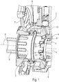
- Figure 1 shows a partially sectioned perspective view of the bottom bracket area of an e-bike with a torque transmission arrangement according to the invention according to a first embodiment.
- the bottom bracket shaft 1 to which the pedals (not shown) of the e-bike are attached, forms a first input shaft of the torque transmission arrangement according to the invention.
- the first input shaft 1 extends through the hollow cylindrical output shaft 3 of the torque transmission arrangement.
- the hollow cylindrical output shaft 3 in turn carries the chainring carrier 7 to which the chainring 6 is attached.
- the drive torque applied to the output shaft 3 is transmitted to the rear wheel of the e-bike via the chain (not shown).
- the torque transmission arrangement according to the invention further comprises a second input shaft 2, which is also designed to be hollow and radially encloses the output shaft 3.
- the second input shaft 2 is designed as a ring gear. It therefore has a conical toothed surface into which the pinion 13 of the output shaft of the electric auxiliary motor of the e-bike engages.
- the second input shaft 2 is thus driven exclusively via the auxiliary drive, not shown further.
- All three shafts, the output shaft 3, the first input shaft 1 and the second input shaft 2 are arranged coaxially to one another and are basically rotatably mounted in relation to one another. They share the in Figure 1 common geometric axis 8 shown.
- the torque arrangement according to the invention is set up in such a way that a torque can be transmitted to the output shaft 3 via both input shafts 1 and 2.
- the torque transmission arrangement according to the invention has two freewheeling functions that are integrated in a single functional unit.
- the first freewheel function prevents a user of the e-bike from having to turn the auxiliary motor when pedaling forward when the auxiliary motor is switched off or not switched on.
- the second freewheel function ensures that the auxiliary motor does not have to be turned against the normal direction of rotation when the user of the e-bike steps backwards on the pedals without a torque on the Transfer rear wheel.
- the rear hub is therefore also equipped with a corresponding freewheel.
- a plurality of cylindrical pinch rollers 4 are arranged between the output shaft 3 and the second input shaft 2, which during normal operation ensure a torque transmission from the second input shaft 2 to the output shaft 3 in the manner of a clamping lock.
- the pinch rollers 4 are distributed evenly over the circumference of the output shaft 3 and are received in corresponding recesses 9 on the outer circumference of the output shaft 3.
- the axes of the pinch rollers 4 are not aligned parallel to the axis 8 of the torque transmission arrangement according to the invention. Rather, they are at an oblique angle to the common axis 8 of output shaft 3, first input shaft 1 and second input shaft 2.
- the pinch rollers 4 thus act between the clamping surfaces of the output shaft 3 and the second input shaft 2, which are essentially conical.
- Figure 2 shows a cross section through the torque transmission arrangement according to the invention orthogonal to the axis 8 in the axial position of the pinch rollers 4.
- the pinch surface 12 on the side of the second input shaft 2 is formed by a rotationally symmetrical conical surface.
- the clamping surface 11 on the output shaft side is formed by the base surface of the recess 9 on the outer circumference of the output shaft 3.
- the clamping surface 11 viewed in the circumferential direction, rises in the clockwise direction or in the drive direction 15, so that the distance between the clamping surface 11 and the clamping surface 12 is reduced in the clockwise direction.
- a second recess 10 is formed in the outer contour of the output shaft 3 next to each recess 9. Pin-shaped projections 5 engage the first input shaft 1, as in FIG Figure 2 shown, into the second recesses 10.
- the peg-shaped extensions 5 are in Figure 1 not shown for the sake of clarity.
- the first input shaft 1 rotates in the illustration in FIG Figure 3 clockwise.
- the peg-shaped extensions 5 of the first input shaft come to rest after overcoming the play 14 with the flanks of the second recesses 10 on the right in the illustration, so that the output shaft 3 is rotated with the first input shaft 1.
- the pinch rollers 4 remain in the left corner of the associated first recess 9 and can rotate freely, as indicated by the arrow in the pinch roller 4 in FIG Figure 3 is illustrated.
- the second input shaft 2 also rotates clockwise, as shown in FIG Figure 4 is shown.
- the second input shaft 2 In order to be able to transmit a torque from the auxiliary motor to the output shaft, the second input shaft 2 must briefly rotate faster than the output shaft 3.
- the pinch roller 4 is entrained by this relative movement and rolls along the rising clamping surface 11 to the right until it is between the The clamping surface 11 of the output shaft 3 and the clamping surface 12 of the second input shaft 2 are jammed and self-locking occurs as a result.
- This state is in Figure 5 shown.
- a torque is now transmitted to the output shaft 3 both via the first input shaft 1 and via the second input shaft 2.
- FIG 7 shows how the torque transmission arrangement according to the invention behaves when the driver of the e-bike steps backwards on the pedals.
- the pin-shaped projection 5 pushes the pinch roller 4 counterclockwise until the pinch roller between the pin-shaped projection 5 and the left flank of the first recess 9 is clamped.
- the torque is now transmitted counterclockwise from the first input shaft or the peg-shaped projection 5 via the pinch roller 4 to the output shaft 3.
- the output shaft 3 rotates counterclockwise with the first input shaft.
- the frictional connection between the output shaft and the second input shaft is canceled, so that the auxiliary motor does not have to be rotated with this backward movement of the pedals.
- a connection of the auxiliary motor in the driving direction of rotation which causes a clockwise rotation of the second input shaft 2, has no influence on the pinch roller 4 and on the backward movement of the first input shaft 1 and the output shaft 3.
- Figure 9 finally shows the behavior when pushing back the e-bike.
- the output shaft 3 rotates counterclockwise and takes the peg-shaped extensions 5 of the first input shaft with it in their movement.
- the pinch roller 4 rolls along the first clamping surface 11 to the right into the blocking position, in which self-locking occurs between the pinch roller 4 and the output shaft 3 and the second input shaft 2.
- the auxiliary motor is therefore turned along with it.
- FIG. 10 shows a cross section through a further embodiment of the torque transmission device according to the invention.
- the torque transmission device is basically constructed in exactly the same way as the torque transmission device according to the exemplary embodiment from FIG Figures 1 to 9 .
- the in Figure 10 The embodiment shown, the torque transmission device additionally has a tensioning element 16, which is designed to support the clamping elements 4 during the transfer into the blocking position.
- the tensioning element 16 is designed in the shape of a ring and rests on corresponding bearing surfaces 18 of the clamping elements 4.
- the support surface 18 is formed on a projection 20 projecting axially from a base body 19 of the clamping element 4.
- the tensioning element is designed to be elastic, so that a tensioning force is generated by the tensioning element.
- the tensioning element 16 By resting the tensioning element 16 at a point on the support surface 18, a force or a torque can thus be generated on the clamping element 4.
- the torque supports the clamping elements 4 during the movement or transfer into the blocking position.
- the tensioning element 16 can, for example, be made of an elastic material such as rubber or caoutchouc, through which the tensioning force is generated.
- the tensioning element 16 can alternatively be made from a spring wire, for example. A worm spring is created by spiraling a wire, which can also generate the tension.
- the clamping elements 4 of the clamping lock must be well greased.
- the projection 20 with the support surface 18 protrudes approximately 1mm to 10mm, preferably 2mm to 5mm from the base body 19 of the clamping element 4, so that the clamping element 16 can rest well and not too much space is required for the projection 20 in the clamping lock.
- the bearing surface 18 extends radially approximately straight from one side of the circumference of the clamping element 4 to the other side of the circumference.
- the support surface 18 preferably runs approximately through the center point, with a cross section running perpendicular to the longitudinal axis of the clamping element 4. As a result, the greatest possible torque can be generated on the clamping element 4 by the support surface 18.
- the support surface 18 has a rounding 21 close to the outer circumference of the clamping element 4. Due to the rounding 21, the tensioning element 16 is less mechanically stressed when it rests on the support surface 18 than if the tensioning element 16 were to rest on a sharp edge.
- the clamping element 16 shown generates a clamping force directed towards the common axis 8.
- the tensioning element 16 should rest against a region of the clamping element 4 close to the axis.
- the area close to the axis is that area of the clamping elements 4 which is shown in FIG Figure 1 considered closer to the common axis 8 of the three shafts 1, 2 and 3.
- the projection 20 thus forms the area close to the axis.
- the clamping element 4 has a base body with a circular cross section and two bulges 17.
- the bulges 17 enlarge the circumference of the clamping element 4 in the manner of two cams, whereby both the power transmission as well as the positioning or the alignment of the clamping element 4 between the second input shaft 2 and the output shaft 3.
Landscapes
- Engineering & Computer Science (AREA)
- General Engineering & Computer Science (AREA)
- Mechanical Engineering (AREA)
- Chemical & Material Sciences (AREA)
- Combustion & Propulsion (AREA)
- Transportation (AREA)
- One-Way And Automatic Clutches, And Combinations Of Different Clutches (AREA)
Claims (17)
- Agencement de transmission de couple destiné à la chaîne cinématique d'un véhicule à propulsion musculaire muni d'un moteur auxiliaire,
avec un arbre de sortie (3),
un premier arbre d'entrée (1) permettant de transmettre à l'arbre de sortie (3) un couple généré au moyen d'une force musculaire,
un second arbre d'entrée (2) permettant de transmettre à l'arbre de sortie (3) un couple généré grâce au moteur auxiliaire,
et avec une fonction de roue libre grâce à laquelle un utilisateur du véhicule à propulsion musculaire n'a pas à faire tourner le moteur auxiliaire lorsque le moteur auxiliaire est éteint,
caractérisé en ce que l'agencement de transmission de couple présente un couplage mécanique conçu pour transmettre un couple du second arbre d'entrée (2) à l'arbre de sortie (3) si un couple agissant sur l'arbre de sortie (3) dans un sens de rotation d'entraînement (15) est appliqué au niveau du premier arbre d'entrée (1), et pour ne transmettre aucun couple du second arbre d'entrée (2) à l'arbre de sortie (3) si un couple agissant sur l'arbre de sortie (3) est appliqué au niveau du premier arbre d'entrée (1) à l'encontre du sens de rotation d'entraînement (15). - Agencement de transmission de couple selon la revendication 1, caractérisé en ce que le couplage mécanique est un couplage à la manière d'un verrou de serrage pouvant être actionné sans alimentation en énergie électrique.
- Agencement de transmission de couple selon la revendication 1 ou 2, caractérisé en ce que l'arbre de sortie (3), le premier arbre d'entrée (1) et le second arbre d'entrée (2) sont agencés de manière coaxiale l'un par rapport à l'autre et sont montés de manière essentiellement contrarotative, dans lequel un engrènement d'entraînement avec jeu, permettant une rotation relative entre le premier arbre d'entrée (1) et l'arbre de sortie (3) avec un certain jeu circonférentiel (14), est constitué entre le premier arbre d'entrée (1) et l'arbre de sortie (3),
dans lequel au moins un élément de serrage (4) à la manière d'un verrou de serrage est agencé entre le second arbre d'entrée (2) et l'arbre de sortie (3) de telle manière que l'élément de serrage (4) se trouve ensuite dans tous les cas dans une position de libération ou est amené dans la position de libération lorsque l'arbre de sortie (3) est mis en rotation dans le sens de rotation d'entraînement (15) par le premier arbre d'entrée (1) et lorsque le second arbre d'entrée (2) ne tourne pas ou tourne dans le sens de rotation d'entraînement plus lentement que l'arbre de sortie (3) et le premier arbre d'entrée (1),
dans lequel l'élément de serrage (4) est amené de la position de libération à une position de verrouillage grâce à une rotation relative entre l'arbre de sortie (3) et le second arbre d'entrée (2) lorsque le second arbre d'entrée (2) tourne brièvement dans le sens de rotation d'entraînement (15) plus rapidement que l'arbre de sortie (3), de sorte qu'un engrènement d'entraînement est établi entre le second arbre d'entrée (2) et l'arbre de sortie (3), dans lequel l'élément de serrage (4) reste dans tous les cas dans la position de verrouillage aussi longtemps qu'un couple agissant dans le sens de rotation d'entraînement (15) est transmis à l'arbre de sortie (3), aussi bien par l'intermédiaire du premier arbre d'entrée (1) que par l'intermédiaire du second arbre d'entrée (2),
et dans lequel le premier arbre d'entrée (1) présente un élément de déverrouillage (5) qui dans tous les cas déplace ensuite de manière active l'élément de serrage (4) de la position de verrouillage vers la position de libération lorsque le premier arbre d'entrée (1) tourne à l'encontre du sens de rotation d'entraînement (15), considéré par rapport à l'arbre de sortie (3), grâce au jeu circonférentiel (14) constitué entre le premier arbre d'entrée (1) et l'arbre de sortie (3). - Agencement de transmission de couple selon la revendication 3, caractérisé en ce que l'élément de serrage (4) est un organe de roulement agencé entre une première surface de serrage (11) de l'arbre de sortie (3) et une seconde surface de serrage (12) du second arbre d'entrée (2), dans lequel la distance entre la première surface de serrage (11) et la seconde surface de serrage (12), considérée dans le sens de rotation d'entraînement (15), se réduit de telle manière qu'un blocage automatique entre l'élément de serrage (4) et la première surface de serrage (11) et la seconde surface de serrage (12) est constitué dans la position de verrouillage de l'élément de serrage (4).
- Agencement de transmission de couple selon la revendication 4, caractérisé en ce que l'élément de serrage (4) est un rouleau de serrage.
- Agencement de transmission de couple selon la revendication 4 ou 5, caractérisé en ce que l'élément de serrage (4) présente une forme cylindrique ou conique.
- Agencement de transmission de couple selon la revendication 6, caractérisé en ce que l'élément de serrage (4), en coupe perpendiculaire à l'axe longitudinal de l'élément de serrage (4), présente une section transversale circulaire ou une section transversale circulaire avec au moins un renflement (17).
- Agencement de transmission de couple selon l'une quelconque des revendications 4 à 7, caractérisé en ce qu'un axe de rotation de l'élément de serrage est parallèle à un axe commun (8) de l'arbre de sortie (3), du premier arbre d'entrée (1) et du second arbre d'entrée (2).
- Agencement de transmission de couple selon l'une quelconque des revendications 4 à 8, caractérisé en ce que la première surface de serrage (11) et la seconde surface de serrage (12) sont formées de surfaces coniques, dans lequel un rayon moyen de la seconde surface de serrage (12) est constant sur la circonférence complète du second arbre d'entrée (2), et dans lequel un rayon moyen de la première surface de serrage (11) varie lorsqu'il est considéré dans la direction circonférentielle.
- Agencement de transmission de couple selon l'une quelconque des revendications 4 à 9, caractérisé en ce que l'élément de serrage (4) est accueilli dans un premier évidement (9) de l'arbre de sortie (3), dans lequel la première surface de serrage (11) est formée d'une surface partielle du premier évidement (9).
- Agencement de transmission de couple selon la revendication 10, caractérisé en ce que, considéré dans le sens de rotation d'entraînement (15), un second évidement (10) présent dans l'arbre de sortie (3) est formé à la suite du premier évidement (9), dans lequel l'élément de déverrouillage (5) du premier arbre d'entrée (1) est une broche qui vient en prise dans le second évidement (10), dans lequel l'engrènement d'entraînement est créé entre le premier arbre d'entrée (1) et l'arbre de sortie (3) dans le sens de rotation d'entraînement (15) grâce à l'engrènement entre broche et second évidement (10), et dans lequel le jeu circonférentiel (14) entre le premier arbre d'entrée (1) et l'arbre de sortie (3) est fourni grâce au fait qu'une extension combinée, considérée dans la direction circonférentielle, du premier évidement (9) et du second évidement (10) est supérieure à une extension combinée, considérée dans la direction circonférentielle, de l'élément de serrage (4) et de la broche.
- Agencement de transmission de couple selon l'une quelconque des revendications 1 à 11, caractérisé en ce que le second arbre d'entrée (2) entoure l'arbre de sortie (3) de manière coaxiale.
- Agencement de transmission de couple selon la revendication 12, caractérisé en ce que le second arbre d'entrée (2) est réalisé sous forme de couronne.
- Agencement de transmission de couple selon l'une quelconque des revendications 1 à 13, caractérisé en ce que le premier arbre d'entrée (1) s'étend à travers l'arbre de sortie (3).
- Agencement de transmission de couple selon l'une quelconque des revendications 1 à 14, caractérisé en ce que l'agencement de transmission de couple présente plusieurs éléments de serrage (4) agencés de manière répartie dans la direction circonférentielle.
- Agencement de transmission de couple selon l'une quelconque des revendications 1 à 15, caractérisé en ce que le verrou de serrage présente un élément de mise en tension annulaire (16) conçu pour supporter les éléments de serrage (4) lorsqu'ils sont amenés dans la position de verrouillage.
- Bicyclette avec un moteur auxiliaire et un agencement de transmission de couple selon l'une quelconque des revendications 1 à 16, dans laquelle le moteur auxiliaire est mis en œuvre en tant que moteur central et est couplé au second arbre d'entrée (2).
Priority Applications (9)
| Application Number | Priority Date | Filing Date | Title |
|---|---|---|---|
| DK19168972.8T DK3722193T3 (da) | 2019-04-12 | 2019-04-12 | Drejningsmomenttransistor og elcykel med drejningsmomenttransistor |
| ES19168972T ES2887300T3 (es) | 2019-04-12 | 2019-04-12 | Transistor de par y bicicleta eléctrica con transistor de par |
| EP19168972.8A EP3722193B1 (fr) | 2019-04-12 | 2019-04-12 | Transistor torque et vélo électrique pourvu de transistor torque |
| US17/593,884 US12065216B2 (en) | 2019-04-12 | 2020-04-02 | Torque transistor and e-bike with torque transistor |
| AU2020272920A AU2020272920A1 (en) | 2019-04-12 | 2020-04-02 | Torque transistor and e-bike with torque transistor |
| JP2021560115A JP7463402B2 (ja) | 2019-04-12 | 2020-04-02 | トルクトランジスタ及び当該トルクトランジスタを備えるeバイク |
| KR1020217036688A KR102914477B1 (ko) | 2019-04-12 | 2020-04-02 | 토크 트랜지스터 및 토크 트랜지스터를 갖는 전기 자전거 |
| CN202080026288.3A CN113677589B (zh) | 2019-04-12 | 2020-04-02 | 扭矩晶体管和带有扭矩晶体管的电动自行车 |
| PCT/EP2020/059412 WO2020207900A1 (fr) | 2019-04-12 | 2020-04-02 | Transistor à couple de tranfert et bicyclette électrique pourvu de transistor à couple de tranfert |
Applications Claiming Priority (1)
| Application Number | Priority Date | Filing Date | Title |
|---|---|---|---|
| EP19168972.8A EP3722193B1 (fr) | 2019-04-12 | 2019-04-12 | Transistor torque et vélo électrique pourvu de transistor torque |
Publications (2)
| Publication Number | Publication Date |
|---|---|
| EP3722193A1 EP3722193A1 (fr) | 2020-10-14 |
| EP3722193B1 true EP3722193B1 (fr) | 2021-06-09 |
Family
ID=66175260
Family Applications (1)
| Application Number | Title | Priority Date | Filing Date |
|---|---|---|---|
| EP19168972.8A Active EP3722193B1 (fr) | 2019-04-12 | 2019-04-12 | Transistor torque et vélo électrique pourvu de transistor torque |
Country Status (9)
| Country | Link |
|---|---|
| US (1) | US12065216B2 (fr) |
| EP (1) | EP3722193B1 (fr) |
| JP (1) | JP7463402B2 (fr) |
| KR (1) | KR102914477B1 (fr) |
| CN (1) | CN113677589B (fr) |
| AU (1) | AU2020272920A1 (fr) |
| DK (1) | DK3722193T3 (fr) |
| ES (1) | ES2887300T3 (fr) |
| WO (1) | WO2020207900A1 (fr) |
Families Citing this family (3)
| Publication number | Priority date | Publication date | Assignee | Title |
|---|---|---|---|---|
| WO2023174689A1 (fr) * | 2022-03-18 | 2023-09-21 | Robert Bosch Gmbh | Dispositif d'entraînement pour une unité d'entraînement d'un vélo électrique, unité d'entraînement et vélo électrique |
| KR20240008087A (ko) | 2022-07-11 | 2024-01-18 | 엘지전자 주식회사 | 모드 전환 시스템 및 이를 포함하는 운동 자전거 |
| DE102023209173A1 (de) * | 2023-09-20 | 2025-03-20 | Robert Bosch Gesellschaft mit beschränkter Haftung | Antriebsvorrichtung für eine Antriebseinheit eines Elektrofahrrads, Antriebseinheit und Elektrofahrrad |
Family Cites Families (11)
| Publication number | Priority date | Publication date | Assignee | Title |
|---|---|---|---|---|
| JP2506047B2 (ja) * | 1993-07-26 | 1996-06-12 | ヤマハ発動機株式会社 | 電動自転車 |
| JP3138795B2 (ja) * | 1994-09-12 | 2001-02-26 | 本田技研工業株式会社 | 自転車用アシストモータの制御方法 |
| JP4036776B2 (ja) * | 2003-03-11 | 2008-01-23 | Ntn株式会社 | 電動補助自転車 |
| DE102012210100A1 (de) | 2011-07-08 | 2013-01-10 | Schaeffler Technologies AG & Co. KG | Freilauf, insbesondere für ein Kurbel-CVT-Getriebe |
| US8813930B2 (en) | 2011-10-17 | 2014-08-26 | Needle Roller Bearing Co., Ltd. | One-way clutch |
| EP3187407B1 (fr) | 2014-08-27 | 2018-12-12 | Panasonic Intellectual Property Management Co., Ltd. | Bicyclette à assistance électrique |
| JP2017047731A (ja) | 2015-08-31 | 2017-03-09 | Ntn株式会社 | 電動補助自転車用減速装置 |
| JP6779044B2 (ja) * | 2016-06-10 | 2020-11-04 | ヤマハ発動機株式会社 | 駆動ユニット及び電動補助自転車 |
| JP6952271B2 (ja) | 2017-03-24 | 2021-10-20 | パナソニックIpマネジメント株式会社 | 電動アシスト自転車およびモータ駆動ユニット |
| CN112810746B (zh) * | 2017-05-23 | 2022-04-29 | 马勒国际有限公司 | 具有功率分流的电动自行车 |
| GB201716311D0 (en) * | 2017-10-05 | 2017-11-22 | Freeflow Tech Limited | Apparatus and Method |
-
2019
- 2019-04-12 DK DK19168972.8T patent/DK3722193T3/da active
- 2019-04-12 ES ES19168972T patent/ES2887300T3/es active Active
- 2019-04-12 EP EP19168972.8A patent/EP3722193B1/fr active Active
-
2020
- 2020-04-02 JP JP2021560115A patent/JP7463402B2/ja active Active
- 2020-04-02 AU AU2020272920A patent/AU2020272920A1/en not_active Abandoned
- 2020-04-02 CN CN202080026288.3A patent/CN113677589B/zh active Active
- 2020-04-02 WO PCT/EP2020/059412 patent/WO2020207900A1/fr not_active Ceased
- 2020-04-02 US US17/593,884 patent/US12065216B2/en active Active
- 2020-04-02 KR KR1020217036688A patent/KR102914477B1/ko active Active
Non-Patent Citations (1)
| Title |
|---|
| None * |
Also Published As
| Publication number | Publication date |
|---|---|
| CN113677589A (zh) | 2021-11-19 |
| CN113677589B (zh) | 2023-09-19 |
| DK3722193T3 (da) | 2021-09-13 |
| US12065216B2 (en) | 2024-08-20 |
| ES2887300T3 (es) | 2021-12-22 |
| JP7463402B2 (ja) | 2024-04-08 |
| KR20210151906A (ko) | 2021-12-14 |
| WO2020207900A1 (fr) | 2020-10-15 |
| AU2020272920A1 (en) | 2021-10-14 |
| EP3722193A1 (fr) | 2020-10-14 |
| KR102914477B1 (ko) | 2026-01-16 |
| JP2022528264A (ja) | 2022-06-09 |
| US20220169335A1 (en) | 2022-06-02 |
Similar Documents
| Publication | Publication Date | Title |
|---|---|---|
| DE69734618T2 (de) | Lärmdämpfungseinheit für Freilauf für ein Fahrrad | |
| DE102014009517B3 (de) | Lenksystem | |
| DE2253475A1 (de) | Antriebsvorrichtung fuer leitspindeln | |
| DE102016012782A1 (de) | Elektrische Servolenkungsvorrichtung | |
| DE102008023759A1 (de) | Lenkvorrichtung für ein Kraftfahrzeug mit einem Lenkrad, einer Lenkwelle und einem Überlagerungsgetriebe | |
| DE112018007518T5 (de) | Fahrzeug-Arretiervorrichtung und Fahrzeug-Lenkvorrichtung mit einer solchen | |
| EP3164326A1 (fr) | Unité d'entraînement pour une bicyclette à assistance électrique | |
| EP3722193A1 (fr) | Transistor torque et vélo électrique pourvu de transistor torque | |
| DE112020005479T5 (de) | Elektrische (steer-by-wire-) lenkvorrichtung | |
| DE102022101279A1 (de) | Kraftfahrzeug mit einem Koppelgetriebe und mit einer funktionsgesicherten Parksperrvorrichtung | |
| EP0913600B1 (fr) | Dispositif pour la production d'un mouvement rotatif ou linéaire | |
| EP2502819A1 (fr) | Entraînement auxiliaire électrique pour vélos | |
| DE69002740T2 (de) | Vorrichtung zum Einschalten eines 4-Rad-Antriebes in einem Fahrzeug. | |
| DE102019215712B4 (de) | Freilauf, Antriebsvorrichtung und Fahrrad | |
| DE4420054A1 (de) | Rotationsübertragungsvorrichtung | |
| DE102011086547A1 (de) | Parksperre | |
| DE102011006816A1 (de) | Zahnstangenlenkgetriebe | |
| DE4242814A1 (fr) | ||
| DE102011006890A1 (de) | Lenkvorrichtung, insbesondere für eine Hinterradlenkung | |
| DE102019207075B3 (de) | Parksperrensystem | |
| DE19516216C2 (de) | Fahrzeug mit Schubkurbelantrieb | |
| DE102011085717A1 (de) | Parksperre | |
| EP1794468A1 (fr) | Roue libre a liaison de forme | |
| DE4226818A1 (de) | Energierückgewinnungsvorrichtung für radgetriebene Fahrzeuge | |
| DE102009021396B4 (de) | Rollenfreilaufkupplung |
Legal Events
| Date | Code | Title | Description |
|---|---|---|---|
| PUAI | Public reference made under article 153(3) epc to a published international application that has entered the european phase |
Free format text: ORIGINAL CODE: 0009012 |
|
| STAA | Information on the status of an ep patent application or granted ep patent |
Free format text: STATUS: REQUEST FOR EXAMINATION WAS MADE |
|
| 17P | Request for examination filed |
Effective date: 20200325 |
|
| AK | Designated contracting states |
Kind code of ref document: A1 Designated state(s): AL AT BE BG CH CY CZ DE DK EE ES FI FR GB GR HR HU IE IS IT LI LT LU LV MC MK MT NL NO PL PT RO RS SE SI SK SM TR |
|
| AX | Request for extension of the european patent |
Extension state: BA ME |
|
| GRAP | Despatch of communication of intention to grant a patent |
Free format text: ORIGINAL CODE: EPIDOSNIGR1 |
|
| STAA | Information on the status of an ep patent application or granted ep patent |
Free format text: STATUS: GRANT OF PATENT IS INTENDED |
|
| INTG | Intention to grant announced |
Effective date: 20201120 |
|
| GRAS | Grant fee paid |
Free format text: ORIGINAL CODE: EPIDOSNIGR3 |
|
| GRAA | (expected) grant |
Free format text: ORIGINAL CODE: 0009210 |
|
| STAA | Information on the status of an ep patent application or granted ep patent |
Free format text: STATUS: THE PATENT HAS BEEN GRANTED |
|
| AK | Designated contracting states |
Kind code of ref document: B1 Designated state(s): AL AT BE BG CH CY CZ DE DK EE ES FI FR GB GR HR HU IE IS IT LI LT LU LV MC MK MT NL NO PL PT RO RS SE SI SK SM TR |
|
| REG | Reference to a national code |
Ref country code: GB Ref legal event code: FG4D Free format text: NOT ENGLISH |
|
| REG | Reference to a national code |
Ref country code: CH Ref legal event code: EP Ref country code: AT Ref legal event code: REF Ref document number: 1400271 Country of ref document: AT Kind code of ref document: T Effective date: 20210615 |
|
| REG | Reference to a national code |
Ref country code: DE Ref legal event code: R096 Ref document number: 502019001567 Country of ref document: DE |
|
| REG | Reference to a national code |
Ref country code: IE Ref legal event code: FG4D Free format text: LANGUAGE OF EP DOCUMENT: GERMAN |
|
| REG | Reference to a national code |
Ref country code: NL Ref legal event code: FP |
|
| REG | Reference to a national code |
Ref country code: DK Ref legal event code: T3 Effective date: 20210908 |
|
| REG | Reference to a national code |
Ref country code: LT Ref legal event code: MG9D |
|
| REG | Reference to a national code |
Ref country code: SE Ref legal event code: TRGR |
|
| PG25 | Lapsed in a contracting state [announced via postgrant information from national office to epo] |
Ref country code: HR Free format text: LAPSE BECAUSE OF FAILURE TO SUBMIT A TRANSLATION OF THE DESCRIPTION OR TO PAY THE FEE WITHIN THE PRESCRIBED TIME-LIMIT Effective date: 20210609 Ref country code: LT Free format text: LAPSE BECAUSE OF FAILURE TO SUBMIT A TRANSLATION OF THE DESCRIPTION OR TO PAY THE FEE WITHIN THE PRESCRIBED TIME-LIMIT Effective date: 20210609 Ref country code: FI Free format text: LAPSE BECAUSE OF FAILURE TO SUBMIT A TRANSLATION OF THE DESCRIPTION OR TO PAY THE FEE WITHIN THE PRESCRIBED TIME-LIMIT Effective date: 20210609 Ref country code: BG Free format text: LAPSE BECAUSE OF FAILURE TO SUBMIT A TRANSLATION OF THE DESCRIPTION OR TO PAY THE FEE WITHIN THE PRESCRIBED TIME-LIMIT Effective date: 20210909 |
|
| PG25 | Lapsed in a contracting state [announced via postgrant information from national office to epo] |
Ref country code: GR Free format text: LAPSE BECAUSE OF FAILURE TO SUBMIT A TRANSLATION OF THE DESCRIPTION OR TO PAY THE FEE WITHIN THE PRESCRIBED TIME-LIMIT Effective date: 20210910 Ref country code: RS Free format text: LAPSE BECAUSE OF FAILURE TO SUBMIT A TRANSLATION OF THE DESCRIPTION OR TO PAY THE FEE WITHIN THE PRESCRIBED TIME-LIMIT Effective date: 20210609 Ref country code: NO Free format text: LAPSE BECAUSE OF FAILURE TO SUBMIT A TRANSLATION OF THE DESCRIPTION OR TO PAY THE FEE WITHIN THE PRESCRIBED TIME-LIMIT Effective date: 20210909 Ref country code: LV Free format text: LAPSE BECAUSE OF FAILURE TO SUBMIT A TRANSLATION OF THE DESCRIPTION OR TO PAY THE FEE WITHIN THE PRESCRIBED TIME-LIMIT Effective date: 20210609 |
|
| REG | Reference to a national code |
Ref country code: ES Ref legal event code: FG2A Ref document number: 2887300 Country of ref document: ES Kind code of ref document: T3 Effective date: 20211222 |
|
| PG25 | Lapsed in a contracting state [announced via postgrant information from national office to epo] |
Ref country code: CZ Free format text: LAPSE BECAUSE OF FAILURE TO SUBMIT A TRANSLATION OF THE DESCRIPTION OR TO PAY THE FEE WITHIN THE PRESCRIBED TIME-LIMIT Effective date: 20210609 Ref country code: SM Free format text: LAPSE BECAUSE OF FAILURE TO SUBMIT A TRANSLATION OF THE DESCRIPTION OR TO PAY THE FEE WITHIN THE PRESCRIBED TIME-LIMIT Effective date: 20210609 Ref country code: RO Free format text: LAPSE BECAUSE OF FAILURE TO SUBMIT A TRANSLATION OF THE DESCRIPTION OR TO PAY THE FEE WITHIN THE PRESCRIBED TIME-LIMIT Effective date: 20210609 Ref country code: PT Free format text: LAPSE BECAUSE OF FAILURE TO SUBMIT A TRANSLATION OF THE DESCRIPTION OR TO PAY THE FEE WITHIN THE PRESCRIBED TIME-LIMIT Effective date: 20211011 Ref country code: SK Free format text: LAPSE BECAUSE OF FAILURE TO SUBMIT A TRANSLATION OF THE DESCRIPTION OR TO PAY THE FEE WITHIN THE PRESCRIBED TIME-LIMIT Effective date: 20210609 Ref country code: EE Free format text: LAPSE BECAUSE OF FAILURE TO SUBMIT A TRANSLATION OF THE DESCRIPTION OR TO PAY THE FEE WITHIN THE PRESCRIBED TIME-LIMIT Effective date: 20210609 |
|
| PG25 | Lapsed in a contracting state [announced via postgrant information from national office to epo] |
Ref country code: PL Free format text: LAPSE BECAUSE OF FAILURE TO SUBMIT A TRANSLATION OF THE DESCRIPTION OR TO PAY THE FEE WITHIN THE PRESCRIBED TIME-LIMIT Effective date: 20210609 |
|
| REG | Reference to a national code |
Ref country code: DE Ref legal event code: R097 Ref document number: 502019001567 Country of ref document: DE |
|
| PLBE | No opposition filed within time limit |
Free format text: ORIGINAL CODE: 0009261 |
|
| STAA | Information on the status of an ep patent application or granted ep patent |
Free format text: STATUS: NO OPPOSITION FILED WITHIN TIME LIMIT |
|
| 26N | No opposition filed |
Effective date: 20220310 |
|
| PG25 | Lapsed in a contracting state [announced via postgrant information from national office to epo] |
Ref country code: AL Free format text: LAPSE BECAUSE OF FAILURE TO SUBMIT A TRANSLATION OF THE DESCRIPTION OR TO PAY THE FEE WITHIN THE PRESCRIBED TIME-LIMIT Effective date: 20210609 |
|
| PG25 | Lapsed in a contracting state [announced via postgrant information from national office to epo] |
Ref country code: MC Free format text: LAPSE BECAUSE OF FAILURE TO SUBMIT A TRANSLATION OF THE DESCRIPTION OR TO PAY THE FEE WITHIN THE PRESCRIBED TIME-LIMIT Effective date: 20210609 Ref country code: LU Free format text: LAPSE BECAUSE OF NON-PAYMENT OF DUE FEES Effective date: 20220412 |
|
| PG25 | Lapsed in a contracting state [announced via postgrant information from national office to epo] |
Ref country code: IE Free format text: LAPSE BECAUSE OF NON-PAYMENT OF DUE FEES Effective date: 20220412 |
|
| PG25 | Lapsed in a contracting state [announced via postgrant information from national office to epo] |
Ref country code: MK Free format text: LAPSE BECAUSE OF FAILURE TO SUBMIT A TRANSLATION OF THE DESCRIPTION OR TO PAY THE FEE WITHIN THE PRESCRIBED TIME-LIMIT Effective date: 20210609 Ref country code: CY Free format text: LAPSE BECAUSE OF FAILURE TO SUBMIT A TRANSLATION OF THE DESCRIPTION OR TO PAY THE FEE WITHIN THE PRESCRIBED TIME-LIMIT Effective date: 20210609 |
|
| PG25 | Lapsed in a contracting state [announced via postgrant information from national office to epo] |
Ref country code: HU Free format text: LAPSE BECAUSE OF FAILURE TO SUBMIT A TRANSLATION OF THE DESCRIPTION OR TO PAY THE FEE WITHIN THE PRESCRIBED TIME-LIMIT; INVALID AB INITIO Effective date: 20190412 |
|
| PG25 | Lapsed in a contracting state [announced via postgrant information from national office to epo] |
Ref country code: TR Free format text: LAPSE BECAUSE OF FAILURE TO SUBMIT A TRANSLATION OF THE DESCRIPTION OR TO PAY THE FEE WITHIN THE PRESCRIBED TIME-LIMIT Effective date: 20210609 |
|
| PG25 | Lapsed in a contracting state [announced via postgrant information from national office to epo] |
Ref country code: MT Free format text: LAPSE BECAUSE OF FAILURE TO SUBMIT A TRANSLATION OF THE DESCRIPTION OR TO PAY THE FEE WITHIN THE PRESCRIBED TIME-LIMIT Effective date: 20210609 |
|
| PGFP | Annual fee paid to national office [announced via postgrant information from national office to epo] |
Ref country code: SE Payment date: 20250311 Year of fee payment: 7 |
|
| PGFP | Annual fee paid to national office [announced via postgrant information from national office to epo] |
Ref country code: NL Payment date: 20250422 Year of fee payment: 7 |
|
| PGFP | Annual fee paid to national office [announced via postgrant information from national office to epo] |
Ref country code: DE Payment date: 20250417 Year of fee payment: 7 |
|
| PGFP | Annual fee paid to national office [announced via postgrant information from national office to epo] |
Ref country code: ES Payment date: 20250519 Year of fee payment: 7 Ref country code: DK Payment date: 20250423 Year of fee payment: 7 |
|
| PGFP | Annual fee paid to national office [announced via postgrant information from national office to epo] |
Ref country code: BE Payment date: 20250422 Year of fee payment: 7 Ref country code: IT Payment date: 20250430 Year of fee payment: 7 |
|
| PGFP | Annual fee paid to national office [announced via postgrant information from national office to epo] |
Ref country code: FR Payment date: 20250428 Year of fee payment: 7 |
|
| PGFP | Annual fee paid to national office [announced via postgrant information from national office to epo] |
Ref country code: CH Payment date: 20250501 Year of fee payment: 7 |
|
| PGFP | Annual fee paid to national office [announced via postgrant information from national office to epo] |
Ref country code: AT Payment date: 20250416 Year of fee payment: 7 |
|
| PGFP | Annual fee paid to national office [announced via postgrant information from national office to epo] |
Ref country code: GB Payment date: 20260324 Year of fee payment: 8 |
|
| REG | Reference to a national code |
Ref country code: CH Ref legal event code: U11 Free format text: ST27 STATUS EVENT CODE: U-0-0-U10-U11 (AS PROVIDED BY THE NATIONAL OFFICE) Effective date: 20260501 |