EP3722687B1 - Climatiseur - Google Patents
Climatiseur Download PDFInfo
- Publication number
- EP3722687B1 EP3722687B1 EP20158163.4A EP20158163A EP3722687B1 EP 3722687 B1 EP3722687 B1 EP 3722687B1 EP 20158163 A EP20158163 A EP 20158163A EP 3722687 B1 EP3722687 B1 EP 3722687B1
- Authority
- EP
- European Patent Office
- Prior art keywords
- refrigerant
- pipe
- heat exchanger
- air conditioning
- conditioning apparatus
- Prior art date
- Legal status (The legal status is an assumption and is not a legal conclusion. Google has not performed a legal analysis and makes no representation as to the accuracy of the status listed.)
- Active
Links
Images


Classifications
-
- F—MECHANICAL ENGINEERING; LIGHTING; HEATING; WEAPONS; BLASTING
- F24—HEATING; RANGES; VENTILATING
- F24F—AIR-CONDITIONING; AIR-HUMIDIFICATION; VENTILATION; USE OF AIR CURRENTS FOR SCREENING
- F24F5/00—Air-conditioning systems or apparatus not covered by F24F1/00 or F24F3/00, e.g. using solar heat or combined with household units such as an oven or water heater
-
- F—MECHANICAL ENGINEERING; LIGHTING; HEATING; WEAPONS; BLASTING
- F25—REFRIGERATION OR COOLING; COMBINED HEATING AND REFRIGERATION SYSTEMS; HEAT PUMP SYSTEMS; MANUFACTURE OR STORAGE OF ICE; LIQUEFACTION SOLIDIFICATION OF GASES
- F25B—REFRIGERATION MACHINES, PLANTS OR SYSTEMS; COMBINED HEATING AND REFRIGERATION SYSTEMS; HEAT PUMP SYSTEMS
- F25B41/00—Fluid-circulation arrangements
- F25B41/20—Disposition of valves, e.g. of on-off valves or flow control valves
- F25B41/26—Disposition of valves, e.g. of on-off valves or flow control valves of fluid flow reversing valves
-
- F—MECHANICAL ENGINEERING; LIGHTING; HEATING; WEAPONS; BLASTING
- F24—HEATING; RANGES; VENTILATING
- F24F—AIR-CONDITIONING; AIR-HUMIDIFICATION; VENTILATION; USE OF AIR CURRENTS FOR SCREENING
- F24F1/00—Room units for air-conditioning, e.g. separate or self-contained units or units receiving primary air from a central station
- F24F1/0007—Indoor units, e.g. fan coil units
- F24F1/00077—Indoor units, e.g. fan coil units receiving heat exchange fluid entering and leaving the unit as a liquid
-
- F—MECHANICAL ENGINEERING; LIGHTING; HEATING; WEAPONS; BLASTING
- F24—HEATING; RANGES; VENTILATING
- F24F—AIR-CONDITIONING; AIR-HUMIDIFICATION; VENTILATION; USE OF AIR CURRENTS FOR SCREENING
- F24F1/00—Room units for air-conditioning, e.g. separate or self-contained units or units receiving primary air from a central station
- F24F1/06—Separate outdoor units, e.g. outdoor unit to be linked to a separate room comprising a compressor and a heat exchanger
- F24F1/26—Refrigerant piping
- F24F1/32—Refrigerant piping for connecting the separate outdoor units to indoor units
-
- F—MECHANICAL ENGINEERING; LIGHTING; HEATING; WEAPONS; BLASTING
- F24—HEATING; RANGES; VENTILATING
- F24F—AIR-CONDITIONING; AIR-HUMIDIFICATION; VENTILATION; USE OF AIR CURRENTS FOR SCREENING
- F24F11/00—Control or safety arrangements
- F24F11/30—Control or safety arrangements for purposes related to the operation of the system, e.g. for safety or monitoring
- F24F11/41—Defrosting; Preventing freezing
-
- F—MECHANICAL ENGINEERING; LIGHTING; HEATING; WEAPONS; BLASTING
- F24—HEATING; RANGES; VENTILATING
- F24F—AIR-CONDITIONING; AIR-HUMIDIFICATION; VENTILATION; USE OF AIR CURRENTS FOR SCREENING
- F24F11/00—Control or safety arrangements
- F24F11/62—Control or safety arrangements characterised by the type of control or by internal processing, e.g. using fuzzy logic, adaptive control or estimation of values
- F24F11/63—Electronic processing
- F24F11/65—Electronic processing for selecting an operating mode
- F24F11/67—Switching between heating and cooling modes
-
- F—MECHANICAL ENGINEERING; LIGHTING; HEATING; WEAPONS; BLASTING
- F24—HEATING; RANGES; VENTILATING
- F24F—AIR-CONDITIONING; AIR-HUMIDIFICATION; VENTILATION; USE OF AIR CURRENTS FOR SCREENING
- F24F11/00—Control or safety arrangements
- F24F11/70—Control systems characterised by their outputs; Constructional details thereof
- F24F11/80—Control systems characterised by their outputs; Constructional details thereof for controlling the temperature of the supplied air
- F24F11/83—Control systems characterised by their outputs; Constructional details thereof for controlling the temperature of the supplied air by controlling the supply of heat-exchange fluids to heat-exchangers
- F24F11/84—Control systems characterised by their outputs; Constructional details thereof for controlling the temperature of the supplied air by controlling the supply of heat-exchange fluids to heat-exchangers using valves
-
- F—MECHANICAL ENGINEERING; LIGHTING; HEATING; WEAPONS; BLASTING
- F24—HEATING; RANGES; VENTILATING
- F24F—AIR-CONDITIONING; AIR-HUMIDIFICATION; VENTILATION; USE OF AIR CURRENTS FOR SCREENING
- F24F13/00—Details common to, or for air-conditioning, air-humidification, ventilation or use of air currents for screening
- F24F13/02—Ducting arrangements
-
- F—MECHANICAL ENGINEERING; LIGHTING; HEATING; WEAPONS; BLASTING
- F24—HEATING; RANGES; VENTILATING
- F24F—AIR-CONDITIONING; AIR-HUMIDIFICATION; VENTILATION; USE OF AIR CURRENTS FOR SCREENING
- F24F13/00—Details common to, or for air-conditioning, air-humidification, ventilation or use of air currents for screening
- F24F13/30—Arrangement or mounting of heat-exchangers
-
- F—MECHANICAL ENGINEERING; LIGHTING; HEATING; WEAPONS; BLASTING
- F25—REFRIGERATION OR COOLING; COMBINED HEATING AND REFRIGERATION SYSTEMS; HEAT PUMP SYSTEMS; MANUFACTURE OR STORAGE OF ICE; LIQUEFACTION SOLIDIFICATION OF GASES
- F25B—REFRIGERATION MACHINES, PLANTS OR SYSTEMS; COMBINED HEATING AND REFRIGERATION SYSTEMS; HEAT PUMP SYSTEMS
- F25B13/00—Compression machines, plants or systems, with reversible cycle
-
- F—MECHANICAL ENGINEERING; LIGHTING; HEATING; WEAPONS; BLASTING
- F25—REFRIGERATION OR COOLING; COMBINED HEATING AND REFRIGERATION SYSTEMS; HEAT PUMP SYSTEMS; MANUFACTURE OR STORAGE OF ICE; LIQUEFACTION SOLIDIFICATION OF GASES
- F25B—REFRIGERATION MACHINES, PLANTS OR SYSTEMS; COMBINED HEATING AND REFRIGERATION SYSTEMS; HEAT PUMP SYSTEMS
- F25B25/00—Machines, plants or systems, using a combination of modes of operation covered by two or more of the groups F25B1/00 - F25B23/00
- F25B25/005—Machines, plants or systems, using a combination of modes of operation covered by two or more of the groups F25B1/00 - F25B23/00 using primary and secondary systems
-
- F—MECHANICAL ENGINEERING; LIGHTING; HEATING; WEAPONS; BLASTING
- F25—REFRIGERATION OR COOLING; COMBINED HEATING AND REFRIGERATION SYSTEMS; HEAT PUMP SYSTEMS; MANUFACTURE OR STORAGE OF ICE; LIQUEFACTION SOLIDIFICATION OF GASES
- F25B—REFRIGERATION MACHINES, PLANTS OR SYSTEMS; COMBINED HEATING AND REFRIGERATION SYSTEMS; HEAT PUMP SYSTEMS
- F25B41/00—Fluid-circulation arrangements
- F25B41/20—Disposition of valves, e.g. of on-off valves or flow control valves
- F25B41/24—Arrangement of shut-off valves for disconnecting a part of the refrigerant cycle, e.g. an outdoor part
-
- F—MECHANICAL ENGINEERING; LIGHTING; HEATING; WEAPONS; BLASTING
- F25—REFRIGERATION OR COOLING; COMBINED HEATING AND REFRIGERATION SYSTEMS; HEAT PUMP SYSTEMS; MANUFACTURE OR STORAGE OF ICE; LIQUEFACTION SOLIDIFICATION OF GASES
- F25B—REFRIGERATION MACHINES, PLANTS OR SYSTEMS; COMBINED HEATING AND REFRIGERATION SYSTEMS; HEAT PUMP SYSTEMS
- F25B5/00—Compression machines, plants or systems, with several evaporator circuits, e.g. for varying refrigerating capacity
- F25B5/02—Compression machines, plants or systems, with several evaporator circuits, e.g. for varying refrigerating capacity arranged in parallel
-
- F—MECHANICAL ENGINEERING; LIGHTING; HEATING; WEAPONS; BLASTING
- F24—HEATING; RANGES; VENTILATING
- F24F—AIR-CONDITIONING; AIR-HUMIDIFICATION; VENTILATION; USE OF AIR CURRENTS FOR SCREENING
- F24F2140/00—Control inputs relating to system states
- F24F2140/20—Heat-exchange fluid temperature
-
- F—MECHANICAL ENGINEERING; LIGHTING; HEATING; WEAPONS; BLASTING
- F24—HEATING; RANGES; VENTILATING
- F24F—AIR-CONDITIONING; AIR-HUMIDIFICATION; VENTILATION; USE OF AIR CURRENTS FOR SCREENING
- F24F2221/00—Details or features not otherwise provided for
- F24F2221/54—Heating and cooling, simultaneously or alternatively
-
- F—MECHANICAL ENGINEERING; LIGHTING; HEATING; WEAPONS; BLASTING
- F25—REFRIGERATION OR COOLING; COMBINED HEATING AND REFRIGERATION SYSTEMS; HEAT PUMP SYSTEMS; MANUFACTURE OR STORAGE OF ICE; LIQUEFACTION SOLIDIFICATION OF GASES
- F25B—REFRIGERATION MACHINES, PLANTS OR SYSTEMS; COMBINED HEATING AND REFRIGERATION SYSTEMS; HEAT PUMP SYSTEMS
- F25B2313/00—Compression machines, plants or systems with reversible cycle not otherwise provided for
- F25B2313/003—Indoor unit with water as a heat sink or heat source
-
- F—MECHANICAL ENGINEERING; LIGHTING; HEATING; WEAPONS; BLASTING
- F25—REFRIGERATION OR COOLING; COMBINED HEATING AND REFRIGERATION SYSTEMS; HEAT PUMP SYSTEMS; MANUFACTURE OR STORAGE OF ICE; LIQUEFACTION SOLIDIFICATION OF GASES
- F25B—REFRIGERATION MACHINES, PLANTS OR SYSTEMS; COMBINED HEATING AND REFRIGERATION SYSTEMS; HEAT PUMP SYSTEMS
- F25B2313/00—Compression machines, plants or systems with reversible cycle not otherwise provided for
- F25B2313/007—Compression machines, plants or systems with reversible cycle not otherwise provided for three pipes connecting the outdoor side to the indoor side with multiple indoor units
-
- F—MECHANICAL ENGINEERING; LIGHTING; HEATING; WEAPONS; BLASTING
- F25—REFRIGERATION OR COOLING; COMBINED HEATING AND REFRIGERATION SYSTEMS; HEAT PUMP SYSTEMS; MANUFACTURE OR STORAGE OF ICE; LIQUEFACTION SOLIDIFICATION OF GASES
- F25B—REFRIGERATION MACHINES, PLANTS OR SYSTEMS; COMBINED HEATING AND REFRIGERATION SYSTEMS; HEAT PUMP SYSTEMS
- F25B2313/00—Compression machines, plants or systems with reversible cycle not otherwise provided for
- F25B2313/023—Compression machines, plants or systems with reversible cycle not otherwise provided for using multiple indoor units
- F25B2313/0231—Compression machines, plants or systems with reversible cycle not otherwise provided for using multiple indoor units with simultaneous cooling and heating
-
- F—MECHANICAL ENGINEERING; LIGHTING; HEATING; WEAPONS; BLASTING
- F25—REFRIGERATION OR COOLING; COMBINED HEATING AND REFRIGERATION SYSTEMS; HEAT PUMP SYSTEMS; MANUFACTURE OR STORAGE OF ICE; LIQUEFACTION SOLIDIFICATION OF GASES
- F25B—REFRIGERATION MACHINES, PLANTS OR SYSTEMS; COMBINED HEATING AND REFRIGERATION SYSTEMS; HEAT PUMP SYSTEMS
- F25B2313/00—Compression machines, plants or systems with reversible cycle not otherwise provided for
- F25B2313/023—Compression machines, plants or systems with reversible cycle not otherwise provided for using multiple indoor units
- F25B2313/0233—Compression machines, plants or systems with reversible cycle not otherwise provided for using multiple indoor units in parallel arrangements
-
- F—MECHANICAL ENGINEERING; LIGHTING; HEATING; WEAPONS; BLASTING
- F25—REFRIGERATION OR COOLING; COMBINED HEATING AND REFRIGERATION SYSTEMS; HEAT PUMP SYSTEMS; MANUFACTURE OR STORAGE OF ICE; LIQUEFACTION SOLIDIFICATION OF GASES
- F25B—REFRIGERATION MACHINES, PLANTS OR SYSTEMS; COMBINED HEATING AND REFRIGERATION SYSTEMS; HEAT PUMP SYSTEMS
- F25B2313/00—Compression machines, plants or systems with reversible cycle not otherwise provided for
- F25B2313/031—Sensor arrangements
- F25B2313/0314—Temperature sensors near the indoor heat exchanger
-
- Y—GENERAL TAGGING OF NEW TECHNOLOGICAL DEVELOPMENTS; GENERAL TAGGING OF CROSS-SECTIONAL TECHNOLOGIES SPANNING OVER SEVERAL SECTIONS OF THE IPC; TECHNICAL SUBJECTS COVERED BY FORMER USPC CROSS-REFERENCE ART COLLECTIONS [XRACs] AND DIGESTS
- Y02—TECHNOLOGIES OR APPLICATIONS FOR MITIGATION OR ADAPTATION AGAINST CLIMATE CHANGE
- Y02B—CLIMATE CHANGE MITIGATION TECHNOLOGIES RELATED TO BUILDINGS, e.g. HOUSING, HOUSE APPLIANCES OR RELATED END-USER APPLICATIONS
- Y02B30/00—Energy efficient heating, ventilation or air conditioning [HVAC]
- Y02B30/70—Efficient control or regulation technologies, e.g. for control of refrigerant flow, motor or heating
Definitions
- Air conditioning apparatuses are apparatuses that maintain air within a predetermined space in the most proper state according to the use and purpose thereof.
- such an air conditioning apparatus includes a compressor, a condenser, an expansion device, and evaporator.
- the air conditioning apparatus has a refrigerant cycle in which compression, condensation, expansion, and evaporation processes of a refrigerant are performed to cool or heat a predetermined space.
- the predetermined space may be variously provided according to a place at which the air conditioning apparatus is used.
- the air conditioning apparatus may be used in a home or an office.
- an outdoor heat exchanger provided in an outdoor unit may serve as a condenser, and an indoor heat exchanger provided in an indoor unit may serve as an evaporator.
- the indoor heat exchanger may serve as the condenser, and the outdoor heat exchanger may serve as the evaporator.
- the predetermined fluid may include water.
- the air conditioning apparatus includes an outdoor unit, a heat medium converter, and an indoor unit.
- the heat medium converter includes a heat exchanger, a fastening device disposed at an upstream side of the heat exchanger, and a refrigerant flow path changing device disposed at a downstream side of the heat exchanger.
- the refrigerant flow path changing device is connected to a refrigerant pipe through which a refrigerant that is in a low-temperature state flows during the cooling operation.
- the refrigerant in the cooling operation, when a portion of a plurality of heat exchangers is used, if leakage of the refrigerant is prevented by the fastening device disposed at the upstream side of the heat exchanger that is not used, the refrigerant may flow along the refrigerant pipe to generate a refrigerant flow in the heat exchanger.
- the refrigerant may flow along the refrigerant pipe to generate a refrigerant flow in the heat exchanger.
- water is frozen in a flow path of the heat exchanger, through which the water flows.
- GB 2 213 248 A provides an air-conditioning apparatus comprising an outdoor side unit having a compressor and an outdoor heat exchanger placed in contact with an outside air or a water, a plurality of room units having an indoor heat exchanger placed in contact with an indoor air for selectively providing heating or cooling, wherein a high-pressure gas pipe, connected at one end thereof to said compressor, has high-side branch pipes, a low-pressure gas pipe being connected at one end thereof to said compressor and having low- side branch pipes, at least one of said high-side branch pipes and at least one of said low-side branch pipes being connected to one end of said outdoor heat exchanger via an outside valve for changing refrigerant flow, an other portion of said high-side branch pipes having auxiliary high side pipes, an other portion of said lowside branch pipes having auxiliary low-side pipes, said auxiliary high-side pipes and said auxiliary low-side pipes being connected to one end of said indoor heat exchangers via an inside valves for changing refrigerant flow, a liquid pipe being connected to the other end of said outdoor heat exchange
- WO 2011/064830 A1 presenting an air-conditioning device
- JP 2001 336858 A presenting an air conditioning apparatus
- US 2014/033749 A1 presenting a multi air-conditioning apparatus
- US 2008/022710 A1 presenting a simultaneous heating/cooling multi air conditioner also present relevant prior arts.
- An object is to provide an air conditioning apparatus in which water is prevented from being frozen in a water flow path of a heat exchanger even though a refrigerant leaks to an unused heat exchanger when a portion of the plurality of heat exchangers is used during a cooling operation.
- An object is to provide an air conditioning apparatus in which a leaking refrigerant is collected from an unused heat exchanger when the refrigerant leaks to the unused heat exchanger.
- an air conditioning apparatus includes: an outdoor unit through which a refrigerant circulates; an indoor unit through which water circulates; a heat exchange device configured to connect the indoor unit to the outdoor unit, the heat exchange device being configured to perform heat exchange between the refrigerant and the water; and first to third outdoor unit connection pipes configured to connect the outdoor unit to the heat exchange device.
- a control unit is provided and configured to control operation of the air conditioning apparatus and its components.
- the heat exchange apparatus includes a plurality of heat exchangers, and only a portion of the plurality of heat exchangers may be used in the cooling operation.
- the valves disposed at an outlet side of the unused heat exchanger may be maintained in the closed state so that a flow of the refrigerant in the unused heat exchanger occurs even though leakage of the refrigerant occurs in the expansion valve disposed at an inlet side of the unused heat exchanger of the plurality of heat exchanger during the cooling operation.
- the heat exchange device includes at least one of: a first heat exchanger and a second heat exchanger; a first branch pipe and a second branch pipe, which are branched from the first outdoor unit connection pipe; a first valve provided in each of the first branch pipe and the second branch pipe; a third branch pipe and a fourth branch pipe, which are branched from the second outdoor unit connection pipe; a second valve provided in each of the third branch pipe and the fourth branch pipe; a first refrigerant pipe and a second refrigerant pipe, which are branched from the third outdoor unit connection pipe; a first expansion valve provided in the first refrigerant pipe; and a second expansion valve provided in the second refrigerant pipe.
- the air conditioning apparatus performs a cooling operation
- the first valve is closed, the second valve provided in the third branch pipe is opened, the second valve provided in the fourth branch pipe is closed, the first expansion valve is opened, and the second expansion valve is closed.
- the heat exchange device further includes a first bypass pipe bypassing the second valve in the third branch pipe and a first bypass valve provided in the first bypass pipe.
- the first bypass pipe may connect a portion of the third branch pipe upstream of the second valve to a portion of the third branch pipe or of a first common gas pipe downstream of the second valve.
- the heat exchange device further includes a second bypass pipe bypassing the second valve in the fourth branch pipe and a second bypass valve provided in the second bypass pipe.
- the second bypass pipe may connect a portion of the fourth branch pipe upstream of the second valve to a portion of the fourth branch pipe or of a second common gas pipe downstream of the second valve.
- the heat exchange device may further include at least one of: a first common gas pipe to which the first branch pipe and the third branch pipe are connected; a first bypass pipe configured to connect the third branch pipe to the first common gas pipe; a first bypass valve provided in the first bypass pipe; a second common gas pipe to which the second branch pipe and the fourth branch pipe are connected; a second bypass pipe configured to connect the fourth branch pipe to the second common gas pipe; and a second bypass valve provided in the second bypass pipe.
- the first common gas pipe may be connected to the first heat exchanger and/or the second common gas pipe may be connected to the second heat exchanger.
- the first common gas pipe may be connected to the first branch pipe and the third branch pipe downstream of the first valve in the first branch pipe and the second valve in the third branch pipe, respectively. That is, the first common gas pipe may be connected to the first branch pipe and the third branch pipe at a position between the first heat exchanger and the first valve in the first branch pipe and the second valve in the third branch pipe, respectively.
- the first common gas pipe may be connected to the first heat exchanger.
- a second common gas pipe may be connected to the second heat exchanger.
- the first refrigerant pipe may be connected to the first heat exchanger.
- the second refrigerant pipe may be connected to the second heat exchanger.
- Each of the bypass valves may be a valve that is capable of adjusting a flow rate of the refrigerant.
- Each of the heat exchangers includes: a refrigerant flow path through which the refrigerant flows; and a water flow path through which the water to be heat-exchanged with the refrigerant within the refrigerant flow path flows, wherein the water flowing through the water flow path flows to the indoor unit.
- the air conditioning apparatus further includes a temperature sensor configured to sense a temperature of the refrigerant flow path of the second heat exchanger.
- a pump configured to the water to the water flow path of the second heat exchanger may operate.
- the pump stops after the pump may operate for a predetermined time or the pump intermittently turns on/off.
- the second bypass valve When it is sensed that the refrigerant is accumulated in the refrigerant flow path of the second heat exchanger, the second bypass valve is opened in a state in which the first bypass valve is closed.
- the second bypass valve may intermittently operate several times.
- the second bypass valve may operate at predetermined time intervals from a time point at which the second heat exchanger is not used.
- the first valve may be closed, the second valve may be opened, the first expansion valve and the second expansion valve may be opened, and each of the bypass valves may be closed.
- the first valve When the air conditioning apparatus performs a heating operation, the first valve may be opened, the second valve may be closed, the first expansion valve and the second expansion valve may be opened, and each of the bypass valves may be closed.
- an air conditioning apparatus in another embodiment not part of the invention, includes: an outdoor unit through which a refrigerant circulates; a plurality of indoor units through which water circulates; and a heat exchange device configured to connect the outdoor unit to the plurality of indoor units, the heat exchange device being configured to perform heat exchange between the refrigerant and the water, wherein the heat exchange device includes: a plurality of heat exchangers, each of which includes a refrigerant flow path and a water flow path; a plurality of expansion valves configured to expand the refrigerant to be introduced into each of the plurality of heat exchangers during a cooling operation; and a refrigerant collection part configured to collect the refrigerant accumulated in the heat exchanger, which is not used, into the outdoor unit when some of the heat exchangers are used, the rest heat exchangers are not used.
- a control unit may be provided and configured to control operation of the air conditioning apparatus and its components.
- the heat exchange device may include: a high-pressure pipe through which a high-pressure refrigerant flows; a first valve provided in the high-pressure pipe; a low-pressure pipe through which a low-pressure refrigerant flows; and a second valve provided in the low-pressure pipe, wherein the refrigerant collection part may include: a bypass pipe connected to the low-pressure pipe so that the refrigerant flows by bypassing the second valve of the low-pressure pipe, and a bypass valve provided in the bypass pipe.
- the second valve of the low-pressure pipe corresponding to the heat exchanger, which is not used, may be maintained in a closed state.
- the bypass valve may be opened to collect the refrigerant accumulated in the heat exchanger, which is not used, into the outdoor unit.
- the bypass valve may intermittently operate several times.
- the bypass valve may operate at predetermined time intervals from a time point at which the rest heat exchangers are not used.
- first, second, A, B, (a) and (b) may be used.
- Each of the terms is merely used to distinguish the corresponding component from other components, and does not delimit an essence, an order or a sequence of the corresponding component. It should be understood that when one component is “connected”, “coupled” or “joined” to another component, the former may be directly connected or jointed to the latter or may be “connected”, coupled” or “joined” to the latter with a third component interposed therebetween.
- FIG. 1 is a schematic view illustrating a configuration of an air conditioning apparatus according to an embodiment of the invention
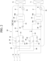
- FIG. 2 is a cycle diagram illustrating the configuration of the air conditioning apparatus according to an embodiment of the invention.
- an air conditioning apparatus 1 according to an embodiment is defined in claim 1.
- it is connected to an outdoor unit 10, an indoor unit 50, and a heat exchange device connected to the outdoor unit 10 and the indoor unit 50.
- the outdoor unit 10 and the heat exchange device 100 may be fluidly connected by a first fluid.
- the first fluid may include a refrigerant.
- the refrigerant may flow through a refrigerant flow path of a heat exchanger, which is provided in the heat exchange device 100, and the outdoor unit 10.
- the outdoor unit 10 may include a compressor 11 and an outdoor heat exchanger 15.
- An outdoor fan 16 may be provided at one side of the outdoor heat exchanger 15 to blow external air toward the outdoor heat exchanger 15 so that heat exchange between the external air and the refrigerant of the outdoor heat exchanger 15 is performed.
- the outdoor unit 10 may further include a main expansion valve 18 (EEV).
- the air conditioning apparatus 1 further includes connection pipes 20, 25, and 27 connecting the outdoor unit 10 to the heat exchange device 100.
- the connection pipes 20, 25, and 27 includes a first outdoor unit connection pipe 20 as a gas pipe (a high-pressure gas pipe) through which a high-pressure gas refrigerant flows, a second outdoor unit connection pipe 25 as a gas pipe (a low-pressure gas pipe) through which a low-pressure gas refrigerant flows, and a third outdoor unit connection pipe 27 as a liquid pipe through which a liquid refrigerant flows.
- a first outdoor unit connection pipe 20 as a gas pipe (a high-pressure gas pipe) through which a high-pressure gas refrigerant flows
- a second outdoor unit connection pipe 25 as a gas pipe (a low-pressure gas pipe) through which a low-pressure gas refrigerant flows
- a third outdoor unit connection pipe 27 as a liquid pipe through which a liquid refrigerant flows.
- the outdoor unit 10 and the heat exchange device 100 may have a "three pipe connection structure", and the refrigerant may circulate through the outdoor unit 10 and the heat exchange device 100 by the three connection pipes 20, 25, and 27.
- the heat exchange device 100 and the indoor unit 50 may be fluidly connected by a second fluid.
- the second fluid may include water.
- the water may flow through a water flow path of a heat exchanger, which is provided in the heat exchange device 100, and the outdoor unit 10.
- the heat exchange device 100 includes a plurality of heat exchangers 140 and 141.
- Each of the heat exchangers 140 and 141 may include, for example, a plate heat exchanger.
- the indoor unit 50 may include a plurality of indoor units 60 and 70.
- the number of plurality of indoor units 60 and 70 is not limited.
- two indoor units 60 and 70 are connected to the heat exchange device 100.
- the plurality of indoor units 60 and 70 may include a first indoor unit 60 and a second indoor unit 70
- the air conditioning apparatus 1 may further include pipes 30 and 35 connecting the heat exchange device 100 to the indoor unit 50.
- the pipes 30 and 35 may include a first indoor unit connection pipe 30 and a second indoor unit connection pipe 35, which connect the heat exchange device 100 to each of indoor units 60 and 70.
- the water may circulate through the heat exchange device 100 and the indoor unit 50 via the indoor unit connection pipes 30 and 50.
- the number of indoor units increases, the number of pipes connecting the heat exchange device 100a to the indoor units may also increase.
- the refrigerant circulating through the outdoor unit 10 and the heat exchange device 100 and the water circulating through the heat exchange device 100 and the indoor unit 50 are heat-exchanged with each other through the heat exchangers 140 and 141 provided in the heat exchange device 100.
- the water cooled or heated through the heat exchange may be heat-exchanged with the indoor heat exchangers 61 and 71 to perform cooling or heating in the indoor space.
- the plurality of heat exchangers 140 and 141 may be provided in the same number as the number of plurality of indoor units 60 and 70. Alternatively, two or more indoor units may be connected to one heat exchanger.
- the heat exchange device 100 includes a first heat exchanger 140 and a second heat exchanger 141, which are fluidly connected to the indoor units 60 and 70, respectively.
- the first heat exchanger 140 and the second heat exchanger 141 may have the same structure.
- Each of the heat exchangers 140 and 141 may include a plate heat exchanger as an example, and the water flow path and the refrigerant flow path may be alternately stacked.
- Each of the heat exchangers 140 and 141 includes refrigerant flow paths 140a and 141a and water flow paths 140b and 141b.
- the refrigerant flow paths 140a and 141a may be fluidly connected to the outdoor unit 10, and the refrigerant discharged from the outdoor unit 10 may be introduced into the refrigerant flow paths 140a and 141a, and then the refrigerant passing through the refrigerant flow paths 140a and 141a may be introduced into the outdoor unit 10.
- Each of the water flow paths 140b and 141b may be connected to each of the indoor units 60 and 70, and the water discharged from each of the indoor units 60 and 70 may be introduced into the water flow paths 140b and 141b, and then the water passing through the water flow path 140b may be introduced into each of the indoor units 60 and 70.
- the heat exchange device 100 includes a first branch pipe 101 and a second branch pipe 102, which are branched from the first outdoor unit connection pipe 20.
- a high-pressure refrigerant may flow through the first branch pipe 101 and the second branch pipe 102. Therefore, the first branch pipe 101 and the second branch pipe 102 may be referred to as high-pressure pipes.
- the first branch pipes 101 and the second branch pipes 102 are provided with first valves 103 and 104, respectively.
- the number of branch pipes branched from the first outdoor unit connection pipe 20 is not limited.
- the heat exchange device 100 includes a third branch pipe 105 and a fourth branch pipe 106, which are branched from the second outdoor unit connection pipe 25.
- a low-pressure refrigerant may flow through the third branch pipe 105 and the fourth branch pipe 106. Therefore, the third branch pipe 105 and the fourth branch pipe 106 may be referred to as, for example, low-pressure pipes.
- the third branch pipe 105 and the fourth branch pipe 106 are provided with second valves 107 and 108, respectively.
- the number of branch pipes branched from the second outdoor unit connection pipe 25 is not limited.
- the heat exchange apparatus 100 includes a first common gas pipe 111 to which the first branch pipe 101 and the third branch pipe 105 are connected and a second common gas pipe 112 to which the second branch pipe 102 and the fourth branch pipe are connected.
- the first common gas pipe 111 may be connected to one end of the refrigerant flow path 140a of the first heat exchanger 140.
- the refrigerant pipes 121 and 122 may be connected to the other ends of the refrigerant flow paths 140a and 141a of the heat exchangers 140 and 141, respectively.
- the first refrigerant pipe 121 may be connected to the first heat exchanger 140, and the second refrigerant pipe 122 may be connected to the second heat exchanger 141.
- a first expansion valve 123 is provided in the first refrigerant pipe 121, and a second expansion valve 124 is provided in the second refrigerant pipe 122.
- the first refrigerant pipe 121 and the second refrigerant pipe 122 are connected to the third outdoor unit connection pipe 27.
- Each of the expansion valves 123 and 124 may include, for example, an electronic expansion valve (EEV).
- EEV electronic expansion valve
- the EEV may adjust a degree of opening thereof to allow a pressure of the refrigerant passing through the expansion valve to drop down. For example, when the expansion valve is fully opened, the refrigerant may pass through the expansion valve without dropping down, and when the degree of opening of the expansion valve decreases, the refrigerant may be decompressed. A degree of decompression of the refrigerant may increase as the degree of opening decreases
- the heat exchange device 100 further includes a first bypass pipe 113 connecting the third branch pipe 105 to the first common gas pipe 111.
- the first bypass pipe 113 allows the refrigerant to bypass the second valve 107 of the third branch pipe 105.
- a first control valve 114 is provided in the first bypass pipe 113.
- the heat exchange device 100 further includes a second bypass pipe 115 connecting the fourth branch pipe 106 to the second common gas pipe 112.
- the second bypass pipe 115 allows the refrigerant to bypass the second valve 108 of the fourth branch pipe 106.
- the second bypass pipe 115 is provided with a second control valve 116.
- the first and second control valves 114 and 116 are valves capable of adjusting a flow rate of the refrigerant. That is, the control valve 114, 116 may be an electronic expansion valve that is capable of adjusting an opening degree.
- the indoor unit connection pipes 30 and 35 may include heat exchanger inlet pipes 31 and 36 and heat exchanger outlet pipes 32 and 37.
- Each of the heat exchanger inlet pipes 31 and 36 may be provided with pumps 151 and 152, respectively.
- Each of the heat exchanger inlet pipes 31 and 36 and each of the heat exchanger outlet pipes 32 and 37 may be connected to the indoor heat exchanger 61 and 71, respectively.
- the heat exchanger inlet pipes 31 and 36 serve as indoor unit inlet pipes with respect to the indoor heat exchangers 61 and 71
- the heat exchanger outlet pipes 32 and 37 serve as the indoor heat exchangers 61 and 71 with respect to the indoor heat exchangers 61 and 71.
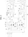
- FIG. 3 is a cycle diagram illustrating flows of the refrigerant and the water in the heat exchange device during the heating operation of the air conditioning apparatus according to an embodiment.
- the air conditioning apparatus 1 when the air conditioning apparatus 1 performs the heating operation (a plurality of indoor units operate to perform the heating operation), the high-pressure gas refrigerant compressed by the compressor 11 of the outdoor unit 10 may flow to the first outdoor unit connection pipe 20 and then be branched into the first branch pipe 101 and the second branch part 102.
- the first valves 103 and 104 of the first and second branch pipes 101 and 102 are opened, and the second valves 107 and 108 of the third and fourth branch pipes 105 and 106 are closed. Also, the first and second bypass valves 114 and 116 are closed.
- the refrigerant branched into the first branch pipe 101 flows along the first common gas pipe 111 and then flows into the refrigerant flow path 140a of the first heat exchanger 140.
- the refrigerant branched into the second branch pipe 102 flows along the second common gas pipe 112 and then flows into the refrigerant flow path 141a of the second heat exchanger 141.
- each of the heat exchangers 140 and 141 may serve as a condenser.
- the first expansion valve 123 and the second expansion valve 124 are opened.
- the refrigerant discharged into the third outdoor unit connection pipe 27 may be introduced into the outdoor unit 10 and then be introduced into the compressor 11.
- the high-pressure refrigerant compressed by the compressor 11 again flows to the heat exchange device 100 through the first outdoor unit connection pipe 20.
- the water flowing through the water flow paths 140b and 141b of the heat exchangers 140 and 141 may be heated by the heat-exchange with the refrigerant, and the heated water may be supplied to each of the indoor heat exchangers 61 and 71 to perform the heating.
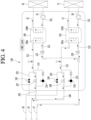
- FIG. 4 is a cycle diagram illustrating flows of the refrigerant and the water in the heat exchange device during the cooling operation of the air conditioning apparatus according to an embodiment.
- a high-pressure liquid refrigerant condensed in the outdoor heat exchanger 15 of the outdoor unit 10 may flow to the third outdoor unit connection pipe 27 and then be distributed into the first refrigerant pipe 121 and the second refrigerant pipe 122.
- the refrigerant may be decompressed into the low-pressure refrigerant while passing through the expansion valves 123 and 124.
- the decompressed refrigerant may be heat-exchanged with the water and thus be evaporated while flowing along the refrigerant flow paths 140a and 141a of the heat exchangers 140 and 141. That is, when the air conditioning apparatus 1 performs the cooling operation, each of the heat exchangers 140 and 141 may serve as an evaporator.
- the air conditioning apparatus 1 performs the cooling operation, the first valves 103 and 104 of the first and second branch pipes 101 and 102 are closed, and the second valves 107 and 108 of the third and fourth branch pipes 105 and 106 are opened. Also, the bypass valves 114 and 116 are closed.
- the refrigerant passing through the refrigerant flow paths 140a and 141a of the heat exchangers 140 and 141 flows to each of the common gas pipes 111 and 112.
- the refrigerant flowing to each of the common gas pipes 111 and 112 flows into the second outdoor unit connection pipe 25 after flowing through the third and fourth branch pipes 105 and 106.
- the refrigerant discharged into the second outdoor unit connection pipe 25 may be introduced into the outdoor unit 10 and then be introduced into the compressor 11.
- the high-pressure refrigerant compressed by the compressor 11 may be condensed in the outdoor heat exchanger 15, and the condensed liquid refrigerant may again flow along the third outdoor unit connection pipe 27.
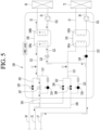
- FIG. 5 is a cycle diagram illustrating flows of the refrigerant and the water when only a portion of the plurality of heat exchangers during the cooling operation of the air conditioning apparatus according to an embodiment.
- FIG. 6 is a cycle diagram illustrating a state in which the refrigerant is collected from an unused heat exchanger.
- the first heat exchanger 140 is used, and the second heat exchanger 141 is not used.
- the following description may be equally applicable to a case in which the second heat exchanger 141 is used, and the first heat exchanger 140 is not used.
- the high-pressure liquid refrigerant condensed in the outdoor heat exchanger 15 of the outdoor unit 10 may flow through the third outdoor unit connection pipe 27 and then be distributed into the first refrigerant pipe 121and the second cold delivery pipe 122.
- the first expansion valve 123 corresponding to the used first heat exchanger 140 is opened, and the second expansion valve 124 corresponding to the unused second heat exchanger 141 is closed.
- valve 107 of the third branch pipe 105 corresponding to the used first heat exchanger 140 is opened, and the valve of the fourth branch pipe 106 corresponding to the unused fourth heat exchanger 141 is closed.
- bypass valves 114 and 116 are in a closed state.
- the refrigerant since the refrigerant is capable of flowing through the first refrigerant pipe 121, the refrigerant flows through the first expansion valve 123 after being expanded while passing through the first heat exchanger 140.
- the refrigerant flowing through the first exchanger 140 flows to the first common gas pipe 111.
- the refrigerant flowing to the first common gas pipe 111 flows to the second outdoor unit connection pipe 25 after flowing through the third branch pipe 105.
- the refrigerant discharged into the second outdoor unit connection pipe 25 may be introduced into the outdoor unit 10 and then be introduced into the compressor 11.
- the high-pressure refrigerant compressed by the compressor 11 may be condensed in the outdoor heat exchanger 15, and the condensed liquid refrigerant may again flow along the third outdoor unit connection pipe 27.
- the second heat exchanger 141 may be prevented from being damaged by the water in the water flow path 141b, which is frozen by the refrigerant.
- the water does not flow to the water flow path 140b of the second heat exchanger 141.
- the leakage of the refrigerant means that the refrigerant passes through the second expansion valve 124.
- the leaking refrigerant is accumulated in the refrigerant flow path 141a of the second heat exchanger 141.
- an opening degree of the second expansion valve 124 is very small, and thus, when a small amount of refrigerant passes through the second expansion valve 124, a temperature of the refrigerant may significantly decrease.
- the water existing in the water flow path 141b may be more easily frozen when compared to a case in which the refrigerant is stagnated in the second heat exchanger 141.
- a temperature sensor 141c may sense an inlet temperature or an outlet temperature of the refrigerant flow path 141a.
- FIG. 6 illustrates an example in which the temperature sensor 141c senses the outlet temperature of the refrigerant flow path 141a.
- the second pump 152 may operate so that the water flows through the water flow path 141b to prevent the water from being frozen in the water flow path 141b.
- the second pump 152 may be stopped after operating for a predetermined time or may be intermittently and repeatedly turned on and off.
- the bypass valve 116 corresponding to the unused heat exchanger may be intermittently opened.
- the second bypass valve 116 corresponding to the unused second heat exchanger 141 is opened.
- an opening degree of the second bypass valve 116 may be adjusted to control an amount of refrigerant that is collected into the outdoor unit 10.
- the refrigerant that is in an abnormal state may leak into the second heat exchanger 141.
- the gas refrigerant may be condensed into the liquid refrigerant.
- most of the refrigerant accumulated in the second heat exchanger 141 may be a liquid refrigerant.
- the opening degree of the second bypass valve 116 may be adjusted so that a small amount of refrigerant is repeatedly collected several times
- the refrigerant may be collected by the second bypass valve 116 at a predetermined time interval from a time point at which the second heat exchanger 141 is not used
- the second bypass valve 116 may operate.
- the refrigerant accumulated in the second heat exchanger 141 flows to the second outdoor unit connection pipe 25 via the second common gas pipe 112 and the second bypass pipe 115.
- the water in the water flow path of the unused heat exchanger may be prevented from being frozen.
- the leaking refrigerant may be collected from the unused heat exchanger to the outdoor unit, and thus the shortage of the refrigerant may be prevented.
- the pipe and the valve, through which the refrigerant accumulated in the unused heat exchanger is collected into the outdoor unit may referred to as a refrigerant collection part.
- the refrigerant collection part may include the bypass pipe and the bypass valve.
Landscapes
- Engineering & Computer Science (AREA)
- General Engineering & Computer Science (AREA)
- Mechanical Engineering (AREA)
- Combustion & Propulsion (AREA)
- Chemical & Material Sciences (AREA)
- Physics & Mathematics (AREA)
- Thermal Sciences (AREA)
- Signal Processing (AREA)
- Life Sciences & Earth Sciences (AREA)
- Sustainable Development (AREA)
- Fuzzy Systems (AREA)
- Mathematical Physics (AREA)
- Fluid Mechanics (AREA)
- Air Conditioning Control Device (AREA)
- Other Air-Conditioning Systems (AREA)
- Compression-Type Refrigeration Machines With Reversible Cycles (AREA)
Claims (12)
- Appareil de climatisation comportant :une unité extérieure (10) pour faire circuler du fluide frigorigène à travers celle-ci ;au moins une unité intérieure (50) pour faire circuler de l'eau à travers celle-ci ;un dispositif d'échange de chaleur (100) relié à l'unité intérieure (50) et à l'unité extérieure (10) pour effectuer un échange de chaleur entre le fluide frigorigène et l'eau ;des premier à troisième tuyaux de raccordement d'unité extérieure (20, 25, 27) reliant l'unité extérieure (10) au dispositif d'échange de chaleur (100), respectivement ; etune unité de commande configurée pour commander au moins une unité parmi l'unité extérieure (10), l'unité intérieure (50) et le dispositif d'échange de chaleur (100);dans lequel le dispositif d'échange de chaleur (100) comporte :un premier échangeur de chaleur (140) et un second échangeur de chaleur (141) ;un premier tuyau d'embranchement (101) et un deuxième tuyau d'embranchement (102), qui bifurquent à partir du premier tuyau de raccordement d'unité extérieure (20), respectivement ;une première vanne (103, 104) respectivement agencée dans le premier tuyau d'embranchement (101) et dans le second tuyau d'embranchement (102) ;un troisième tuyau d'embranchement (105) et un quatrième tuyau d'embranchement (106), qui bifurquent à partir du deuxième tuyau de raccordement d'unité extérieure (25), respectivement ;une seconde vanne (107, 108) respectivement agencée dans le troisième tuyau d'embranchement (105) et dans le quatrième tuyau d'embranchement (106) ;un premier tuyau de dérivation (113) contournant la seconde vanne (107) agencée dans le troisième tuyau d'embranchement (105) et une première vanne de dérivation (114) agencée dans le premier tuyau de dérivation (113) ;un second tuyau de dérivation (115) contournant la seconde vanne (108) agencée dans le quatrième tuyau d'embranchement (106) et une seconde vanne de dérivation (116) agencée dans le second tuyau de dérivation (115) ;un premier tuyau de fluide frigorigène (121) et un second tuyau de fluide frigorigène (122), qui bifurquent à partir du troisième tuyau de raccordement d'unité extérieure (27), respectivement ;une première soupape de détente (123) agencée dans le premier tuyau de fluide frigorigène (121) ; etune seconde soupape de détente (124) agencée dans le second tuyau de fluide frigorigène (122) ;dans lequel chacun des premier et second échangeurs de chaleur (140, 141) comporte :un trajet d'écoulement de fluide frigorigène (140a, 141a) permettant au fluide frigorigène de s'écouler par celui-ci ;un trajet d'écoulement d'eau (140b, 141b) permettant à l'eau d'échanger de la chaleur avec le fluide frigorigène dans le trajet d'écoulement de fluide frigorigène (140a, 141a) pour s'écouler par celui-ci, dans lequel le trajet d'écoulement d'eau (140b, 141b) est relié à l'unité intérieure (50) pour que l'eau s'écoule à partir du trajet d'écoulement d'eau (140b, 141b) de l'échangeur de chaleur (140, 141) respectif jusqu'à l'unité intérieure (50) ; etun capteur de température (141c) conçu pour détecter une température du fluide frigorigène dans le trajet d'écoulement de fluide frigorigène (141a) du second échangeur de chaleur (141) ;dans lequel, lors d'une opération de refroidissement de l'appareil de climatisation, l'unité de commande est configurée pour commander l'utilisation du premier échangeur de chaleur (140) uniquement, la fermeture des premières vannes (103, 104), l'ouverture de la seconde vanne (107) agencée dans le troisième tuyau d'embranchement (105), la fermeture de seconde vanne (108) agencée dans le quatrième tuyau d'embranchement (106), l'ouverture de la première soupape de détente (123) et la fermeture de la seconde soupape de détente (124), la fermeture de la première vanne de dérivation (114) et de la seconde vanne de dérivation (116) ; etdans lequel, lorsque le capteur de température (141c) détecte que du fluide frigorigène s'échappant du second détendeur (124) s'accumule dans le trajet d'écoulement de fluide frigorigène (141a) du second échangeur de chaleur (141), l'unité de commande est configurée pour commander l'ouverture de la seconde vanne de dérivation (116) pendant la fermeture de la première vanne de dérivation (114).
- Appareil de climatisation selon la revendication 1, dans lequel la première et/ou seconde vanne de dérivation (114, 116) est une vanne configurée pour régler un débit du fluide frigorigène.
- Appareil de climatisation selon la revendication 1 ou 2, dans lequel, lorsque l'opération de refroidissement de l'appareil de climatisation débute, l'unité de commande est configurée pour commander le maintien d'un état fermé de la première et/ou seconde vanne de dérivation (114, 116).
- Appareil de climatisation selon la revendication 1, 2 ou 3, dans lequel l'unité de commande est configurée pour commander la fermeture de la première et/ou seconde vanne de dérivation (114, 116) pendant une opération de chauffage de l'appareil de climatisation et/ou pendant une opération de refroidissement où les premier et second échangeurs de chaleur (140, 141) fonctionnent.
- Appareil de climatisation selon l'une quelconque des revendications précédentes, dans lequel le dispositif d'échange de chaleur (100) comporte en outre :un premier tuyau de gaz commun (111) raccordé au premier tuyau d'embranchement (101) et au troisième tuyau d'embranchement (105) ; et/ouun second tuyau de gaz commun (112) raccordé au deuxième tuyau d'embranchement (105) et au quatrième tuyau d'embranchement (106).
- Appareil de climatisation selon la revendication 5, dans lequel le premier tuyau de gaz commun (111) et/ou le premier tuyau de fluide frigorigène (121) est raccordé au premier échangeur de chaleur (140), et/ou dans lequel le second tuyau de gaz commun (112) et/ou le second tuyau de fluide frigorigène (122) est raccordé au second échangeur de chaleur (141).
- Appareil de climatisation selon la revendication 6, comportant en outre un capteur de température (141c) respectivement agencé dans le premier tuyau de gaz commun (111) et/ou dans le second tuyau de gaz commun (112) pour détecter une température du fluide frigorigène s'écoulant dans celui-ci.
- Appareil de climatisation selon l'une quelconque des revendications précédentes, comportant en outre une pompe (152) configurée pour pomper de l'eau jusqu'au trajet d'écoulement d'eau (141b) du second échangeur de chaleur (141),
dans lequel, lorsque la température détectée par le capteur de température (141c) est inférieure à une température de référence, l'unité de commande est configurée pour faire fonctionner la pompe (152). - Appareil de climatisation selon la revendication 8, dans lequel l'unité de commande est configurée pour arrêter le fonctionnement de la pompe (152) après un fonctionnement de la pompe (152) pendant un temps prédéterminé, ou l'unité de commande est configurée pour faire fonctionner la pompe (152) par intermittence.
- Appareil de climatisation selon l'une quelconque des revendications précédentes, dans lequel l'unité de commande est configurée pour faire fonctionner la seconde vanne de dérivation (116) par intermittence à des intervalles de temps prédéterminés à partir d'un instant auquel seul le premier échangeur de chaleur (140) est utilisé pendant l'opération de refroidissement.
- Appareil de climatisation selon l'une quelconque des revendications précédentes, dans lequel, lorsque le premier échangeur de chaleur (140) et le second échangeur de chaleur (141) sont utilisés pendant l'opération de refroidissement de l'appareil de climatisation, l'unité de commande est configurée pour commander la fermeture des premières vannes (103, 104), l'ouverture des secondes vannes (107, 108) et l'ouverture de la première soupape de détente (123) et de la seconde soupape de détente (124).
- Appareil de climatisation selon l'une quelconque des revendications précédentes, dans lequel, pendant une opération de chauffage de l'appareil de climatisation, l'unité de commande est configurée pour commander l'ouverture des premières vannes (103, 104), la fermeture des secondes vannes (107, 108), et l'ouverture de la première soupape de détente (123) et de la seconde soupape de détente (124).
Applications Claiming Priority (1)
| Application Number | Priority Date | Filing Date | Title |
|---|---|---|---|
| KR1020190041168A KR102789599B1 (ko) | 2019-04-09 | 2019-04-09 | 공기 조화 장치 |
Publications (2)
| Publication Number | Publication Date |
|---|---|
| EP3722687A1 EP3722687A1 (fr) | 2020-10-14 |
| EP3722687B1 true EP3722687B1 (fr) | 2024-08-28 |
Family
ID=69701097
Family Applications (1)
| Application Number | Title | Priority Date | Filing Date |
|---|---|---|---|
| EP20158163.4A Active EP3722687B1 (fr) | 2019-04-09 | 2020-02-19 | Climatiseur |
Country Status (6)
| Country | Link |
|---|---|
| US (1) | US11274851B2 (fr) |
| EP (1) | EP3722687B1 (fr) |
| JP (1) | JP7583738B2 (fr) |
| KR (1) | KR102789599B1 (fr) |
| CN (1) | CN113614470B (fr) |
| WO (1) | WO2020209474A1 (fr) |
Families Citing this family (6)
| Publication number | Priority date | Publication date | Assignee | Title |
|---|---|---|---|---|
| KR102688988B1 (ko) * | 2019-05-23 | 2024-07-29 | 엘지전자 주식회사 | 공기조화장치 |
| JP7037087B2 (ja) * | 2020-03-27 | 2022-03-16 | ダイキン工業株式会社 | 冷凍サイクル装置 |
| CN113154636B (zh) * | 2021-04-25 | 2022-05-17 | 珠海格力电器股份有限公司 | 空调器化霜控制方法、装置、存储介质和空调器 |
| CN115729444A (zh) * | 2021-09-01 | 2023-03-03 | 华为技术有限公司 | 一种数据处理方法及装置 |
| EP4224093A1 (fr) * | 2022-02-07 | 2023-08-09 | Daikin Europe N.V. | Dispositif de réfrigération |
| JP2026031080A (ja) * | 2024-08-09 | 2026-02-24 | サンデン株式会社 | 車両用空調装置 |
Family Cites Families (28)
| Publication number | Priority date | Publication date | Assignee | Title |
|---|---|---|---|---|
| JPS6213962A (ja) * | 1985-07-10 | 1987-01-22 | 株式会社日立製作所 | 冷凍装置の凍結防止制御装置 |
| US4878357A (en) | 1987-12-21 | 1989-11-07 | Sanyo Electric Co., Ltd. | Air-conditioning apparatus |
| JP3723413B2 (ja) | 2000-05-29 | 2005-12-07 | 三洋電機株式会社 | 空気調和装置 |
| US7493775B2 (en) * | 2002-10-30 | 2009-02-24 | Mitsubishi Denki Kabushiki Kaisha | Air conditioner |
| KR100667200B1 (ko) * | 2005-05-06 | 2007-01-12 | 삼성전자주식회사 | 에어컨의 냉매회수 제어방법 |
| KR101269462B1 (ko) * | 2005-12-20 | 2013-05-30 | 삼성전자주식회사 | 냉난방 동시형 멀티공기조화기의 제어방법 |
| JP4797727B2 (ja) | 2006-03-22 | 2011-10-19 | ダイキン工業株式会社 | 冷凍装置 |
| KR101282565B1 (ko) | 2006-07-29 | 2013-07-04 | 엘지전자 주식회사 | 냉난방 동시형 멀티 공기 조화기 |
| JP2008116073A (ja) * | 2006-11-01 | 2008-05-22 | Daikin Ind Ltd | 空気調和装置 |
| TWI437512B (zh) * | 2008-01-10 | 2014-05-11 | Fuji Electric Co Ltd | Vending machine |
| JP5178841B2 (ja) * | 2008-10-29 | 2013-04-10 | 三菱電機株式会社 | 空気調和装置 |
| CN102112816B (zh) | 2008-10-29 | 2013-09-18 | 三菱电机株式会社 | 空气调节装置 |
| CN102597657B (zh) * | 2009-10-27 | 2014-10-22 | 三菱电机株式会社 | 空气调节装置 |
| WO2011064830A1 (fr) | 2009-11-30 | 2011-06-03 | 三菱電機株式会社 | Dispositif de climatisation |
| JP5709978B2 (ja) * | 2011-03-28 | 2015-04-30 | 三菱電機株式会社 | 空気調和装置 |
| US9459033B2 (en) | 2012-08-02 | 2016-10-04 | Mitsubishi Electric Corporation | Multi air-conditioning apparatus |
| EP2902726B1 (fr) * | 2012-09-25 | 2020-04-22 | Mitsubishi Electric Corporation | Système pour alimentation en eau chaude et pour conditionnement d'air combinés |
| EP2924366B1 (fr) * | 2012-11-21 | 2020-06-17 | Mitsubishi Electric Corporation | Dispositif de climatisation |
| CN104838218B (zh) * | 2012-12-12 | 2016-09-14 | 三菱电机株式会社 | 空调装置 |
| JP6578094B2 (ja) * | 2014-11-07 | 2019-09-18 | 日立ジョンソンコントロールズ空調株式会社 | 空気調和機及びそのリニューアル方法 |
| KR20160090178A (ko) | 2015-01-21 | 2016-07-29 | 한국전자통신연구원 | 마인드맵 기반의 대화형 콘텐츠 구축 방법 |
| JP6453475B2 (ja) * | 2015-09-11 | 2019-01-16 | 日立ジョンソンコントロールズ空調株式会社 | 空気調和機 |
| JP2017101854A (ja) * | 2015-11-30 | 2017-06-08 | 株式会社富士通ゼネラル | 空気調和装置 |
| KR101653945B1 (ko) * | 2016-07-20 | 2016-09-02 | 엘지전자 주식회사 | 공기 조화 시스템 |
| EP3521731B1 (fr) | 2016-09-30 | 2022-06-15 | Daikin Industries, Ltd. | Dispositif de réfrigération |
| JP6805759B2 (ja) * | 2016-11-29 | 2020-12-23 | 富士電機株式会社 | 冷媒回路装置 |
| JP2018173191A (ja) | 2017-03-31 | 2018-11-08 | 株式会社富士通ゼネラル | 空気調和装置 |
| KR102373851B1 (ko) * | 2017-08-31 | 2022-03-14 | 삼성전자주식회사 | 공기조화기 |
-
2019
- 2019-04-09 KR KR1020190041168A patent/KR102789599B1/ko active Active
- 2019-12-16 JP JP2021559767A patent/JP7583738B2/ja active Active
- 2019-12-16 CN CN201980094384.9A patent/CN113614470B/zh active Active
- 2019-12-16 WO PCT/KR2019/017838 patent/WO2020209474A1/fr not_active Ceased
-
2020
- 2020-02-14 US US16/792,042 patent/US11274851B2/en active Active
- 2020-02-19 EP EP20158163.4A patent/EP3722687B1/fr active Active
Also Published As
| Publication number | Publication date |
|---|---|
| JP7583738B2 (ja) | 2024-11-14 |
| CN113614470B (zh) | 2023-10-10 |
| CN113614470A (zh) | 2021-11-05 |
| KR20200118968A (ko) | 2020-10-19 |
| KR102789599B1 (ko) | 2025-04-03 |
| US11274851B2 (en) | 2022-03-15 |
| EP3722687A1 (fr) | 2020-10-14 |
| US20200326091A1 (en) | 2020-10-15 |
| JP2022528256A (ja) | 2022-06-09 |
| WO2020209474A1 (fr) | 2020-10-15 |
Similar Documents
| Publication | Publication Date | Title |
|---|---|---|
| EP3722687B1 (fr) | Climatiseur | |
| EP3159630B1 (fr) | Climatiseur | |
| US11725855B2 (en) | Air conditioning apparatus | |
| JP7541101B2 (ja) | 空気調和装置 | |
| US11499727B2 (en) | Air conditioning apparatus | |
| US20210231317A1 (en) | Air conditioning apparatus | |
| EP1762796B1 (fr) | Climatiseur | |
| US11578898B2 (en) | Air conditioning apparatus | |
| EP1643196B1 (fr) | Conditioneur d'air | |
| US11519645B2 (en) | Air conditioning apparatus | |
| US12111082B2 (en) | Air conditioning apparatus | |
| EP3715735B1 (fr) | Appareil de climatisation | |
| JP2006250440A (ja) | 空気調和装置 | |
| US11397015B2 (en) | Air conditioning apparatus | |
| KR102688988B1 (ko) | 공기조화장치 | |
| KR101160351B1 (ko) | 멀티 공기조화기 및 그 제어방법 | |
| CN120557705A (zh) | 热泵系统、暖通设备、控制方法和电子设备 | |
| KR20060069711A (ko) | 공기조화기 |
Legal Events
| Date | Code | Title | Description |
|---|---|---|---|
| PUAI | Public reference made under article 153(3) epc to a published international application that has entered the european phase |
Free format text: ORIGINAL CODE: 0009012 |
|
| STAA | Information on the status of an ep patent application or granted ep patent |
Free format text: STATUS: REQUEST FOR EXAMINATION WAS MADE |
|
| 17P | Request for examination filed |
Effective date: 20200219 |
|
| AK | Designated contracting states |
Kind code of ref document: A1 Designated state(s): AL AT BE BG CH CY CZ DE DK EE ES FI FR GB GR HR HU IE IS IT LI LT LU LV MC MK MT NL NO PL PT RO RS SE SI SK SM TR |
|
| AX | Request for extension of the european patent |
Extension state: BA ME |
|
| RBV | Designated contracting states (corrected) |
Designated state(s): AL AT BE BG CH CY CZ DE DK EE ES FI FR GB GR HR HU IE IS IT LI LT LU LV MC MK MT NL NO PL PT RO RS SE SI SK SM TR |
|
| STAA | Information on the status of an ep patent application or granted ep patent |
Free format text: STATUS: EXAMINATION IS IN PROGRESS |
|
| 17Q | First examination report despatched |
Effective date: 20230516 |
|
| GRAP | Despatch of communication of intention to grant a patent |
Free format text: ORIGINAL CODE: EPIDOSNIGR1 |
|
| STAA | Information on the status of an ep patent application or granted ep patent |
Free format text: STATUS: GRANT OF PATENT IS INTENDED |
|
| RIC1 | Information provided on ipc code assigned before grant |
Ipc: F24F 140/20 20180101ALN20240311BHEP Ipc: F25B 41/24 20210101ALI20240311BHEP Ipc: F25B 25/00 20060101ALI20240311BHEP Ipc: F25B 13/00 20060101ALI20240311BHEP Ipc: F24F 13/02 20060101ALI20240311BHEP Ipc: F24F 11/67 20180101ALI20240311BHEP Ipc: F24F 11/65 20180101ALI20240311BHEP Ipc: F24F 5/00 20060101AFI20240311BHEP |
|
| RIC1 | Information provided on ipc code assigned before grant |
Ipc: F24F 140/20 20180101ALN20240318BHEP Ipc: F25B 41/24 20210101ALI20240318BHEP Ipc: F25B 25/00 20060101ALI20240318BHEP Ipc: F25B 13/00 20060101ALI20240318BHEP Ipc: F24F 13/02 20060101ALI20240318BHEP Ipc: F24F 11/67 20180101ALI20240318BHEP Ipc: F24F 11/65 20180101ALI20240318BHEP Ipc: F24F 5/00 20060101AFI20240318BHEP |
|
| INTG | Intention to grant announced |
Effective date: 20240408 |
|
| GRAS | Grant fee paid |
Free format text: ORIGINAL CODE: EPIDOSNIGR3 |
|
| GRAA | (expected) grant |
Free format text: ORIGINAL CODE: 0009210 |
|
| STAA | Information on the status of an ep patent application or granted ep patent |
Free format text: STATUS: THE PATENT HAS BEEN GRANTED |
|
| AK | Designated contracting states |
Kind code of ref document: B1 Designated state(s): AL AT BE BG CH CY CZ DE DK EE ES FI FR GB GR HR HU IE IS IT LI LT LU LV MC MK MT NL NO PL PT RO RS SE SI SK SM TR |
|
| REG | Reference to a national code |
Ref country code: CH Ref legal event code: EP |
|
| REG | Reference to a national code |
Ref country code: DE Ref legal event code: R096 Ref document number: 602020036499 Country of ref document: DE |
|
| REG | Reference to a national code |
Ref country code: IE Ref legal event code: FG4D |
|
| REG | Reference to a national code |
Ref country code: LT Ref legal event code: MG9D |
|
| PG25 | Lapsed in a contracting state [announced via postgrant information from national office to epo] |
Ref country code: NO Free format text: LAPSE BECAUSE OF FAILURE TO SUBMIT A TRANSLATION OF THE DESCRIPTION OR TO PAY THE FEE WITHIN THE PRESCRIBED TIME-LIMIT Effective date: 20241128 |
|
| REG | Reference to a national code |
Ref country code: AT Ref legal event code: MK05 Ref document number: 1718316 Country of ref document: AT Kind code of ref document: T Effective date: 20240828 |
|
| PG25 | Lapsed in a contracting state [announced via postgrant information from national office to epo] |
Ref country code: PT Free format text: LAPSE BECAUSE OF FAILURE TO SUBMIT A TRANSLATION OF THE DESCRIPTION OR TO PAY THE FEE WITHIN THE PRESCRIBED TIME-LIMIT Effective date: 20241230 Ref country code: NL Free format text: LAPSE BECAUSE OF FAILURE TO SUBMIT A TRANSLATION OF THE DESCRIPTION OR TO PAY THE FEE WITHIN THE PRESCRIBED TIME-LIMIT Effective date: 20240828 Ref country code: PL Free format text: LAPSE BECAUSE OF FAILURE TO SUBMIT A TRANSLATION OF THE DESCRIPTION OR TO PAY THE FEE WITHIN THE PRESCRIBED TIME-LIMIT Effective date: 20240828 Ref country code: FI Free format text: LAPSE BECAUSE OF FAILURE TO SUBMIT A TRANSLATION OF THE DESCRIPTION OR TO PAY THE FEE WITHIN THE PRESCRIBED TIME-LIMIT Effective date: 20240828 Ref country code: GR Free format text: LAPSE BECAUSE OF FAILURE TO SUBMIT A TRANSLATION OF THE DESCRIPTION OR TO PAY THE FEE WITHIN THE PRESCRIBED TIME-LIMIT Effective date: 20241129 |
|
| PG25 | Lapsed in a contracting state [announced via postgrant information from national office to epo] |
Ref country code: BG Free format text: LAPSE BECAUSE OF FAILURE TO SUBMIT A TRANSLATION OF THE DESCRIPTION OR TO PAY THE FEE WITHIN THE PRESCRIBED TIME-LIMIT Effective date: 20240828 |
|
| PG25 | Lapsed in a contracting state [announced via postgrant information from national office to epo] |
Ref country code: LV Free format text: LAPSE BECAUSE OF FAILURE TO SUBMIT A TRANSLATION OF THE DESCRIPTION OR TO PAY THE FEE WITHIN THE PRESCRIBED TIME-LIMIT Effective date: 20240828 |
|
| REG | Reference to a national code |
Ref country code: NL Ref legal event code: MP Effective date: 20240828 |
|
| PG25 | Lapsed in a contracting state [announced via postgrant information from national office to epo] |
Ref country code: IS Free format text: LAPSE BECAUSE OF FAILURE TO SUBMIT A TRANSLATION OF THE DESCRIPTION OR TO PAY THE FEE WITHIN THE PRESCRIBED TIME-LIMIT Effective date: 20241228 Ref country code: AT Free format text: LAPSE BECAUSE OF FAILURE TO SUBMIT A TRANSLATION OF THE DESCRIPTION OR TO PAY THE FEE WITHIN THE PRESCRIBED TIME-LIMIT Effective date: 20240828 |
|
| PG25 | Lapsed in a contracting state [announced via postgrant information from national office to epo] |
Ref country code: HR Free format text: LAPSE BECAUSE OF FAILURE TO SUBMIT A TRANSLATION OF THE DESCRIPTION OR TO PAY THE FEE WITHIN THE PRESCRIBED TIME-LIMIT Effective date: 20240828 |
|
| PG25 | Lapsed in a contracting state [announced via postgrant information from national office to epo] |
Ref country code: RS Free format text: LAPSE BECAUSE OF FAILURE TO SUBMIT A TRANSLATION OF THE DESCRIPTION OR TO PAY THE FEE WITHIN THE PRESCRIBED TIME-LIMIT Effective date: 20241128 Ref country code: ES Free format text: LAPSE BECAUSE OF FAILURE TO SUBMIT A TRANSLATION OF THE DESCRIPTION OR TO PAY THE FEE WITHIN THE PRESCRIBED TIME-LIMIT Effective date: 20240828 |
|
| PG25 | Lapsed in a contracting state [announced via postgrant information from national office to epo] |
Ref country code: RS Free format text: LAPSE BECAUSE OF FAILURE TO SUBMIT A TRANSLATION OF THE DESCRIPTION OR TO PAY THE FEE WITHIN THE PRESCRIBED TIME-LIMIT Effective date: 20241128 Ref country code: PT Free format text: LAPSE BECAUSE OF FAILURE TO SUBMIT A TRANSLATION OF THE DESCRIPTION OR TO PAY THE FEE WITHIN THE PRESCRIBED TIME-LIMIT Effective date: 20241230 Ref country code: PL Free format text: LAPSE BECAUSE OF FAILURE TO SUBMIT A TRANSLATION OF THE DESCRIPTION OR TO PAY THE FEE WITHIN THE PRESCRIBED TIME-LIMIT Effective date: 20240828 Ref country code: NO Free format text: LAPSE BECAUSE OF FAILURE TO SUBMIT A TRANSLATION OF THE DESCRIPTION OR TO PAY THE FEE WITHIN THE PRESCRIBED TIME-LIMIT Effective date: 20241128 Ref country code: NL Free format text: LAPSE BECAUSE OF FAILURE TO SUBMIT A TRANSLATION OF THE DESCRIPTION OR TO PAY THE FEE WITHIN THE PRESCRIBED TIME-LIMIT Effective date: 20240828 Ref country code: LV Free format text: LAPSE BECAUSE OF FAILURE TO SUBMIT A TRANSLATION OF THE DESCRIPTION OR TO PAY THE FEE WITHIN THE PRESCRIBED TIME-LIMIT Effective date: 20240828 Ref country code: IS Free format text: LAPSE BECAUSE OF FAILURE TO SUBMIT A TRANSLATION OF THE DESCRIPTION OR TO PAY THE FEE WITHIN THE PRESCRIBED TIME-LIMIT Effective date: 20241228 Ref country code: HR Free format text: LAPSE BECAUSE OF FAILURE TO SUBMIT A TRANSLATION OF THE DESCRIPTION OR TO PAY THE FEE WITHIN THE PRESCRIBED TIME-LIMIT Effective date: 20240828 Ref country code: GR Free format text: LAPSE BECAUSE OF FAILURE TO SUBMIT A TRANSLATION OF THE DESCRIPTION OR TO PAY THE FEE WITHIN THE PRESCRIBED TIME-LIMIT Effective date: 20241129 Ref country code: FI Free format text: LAPSE BECAUSE OF FAILURE TO SUBMIT A TRANSLATION OF THE DESCRIPTION OR TO PAY THE FEE WITHIN THE PRESCRIBED TIME-LIMIT Effective date: 20240828 Ref country code: ES Free format text: LAPSE BECAUSE OF FAILURE TO SUBMIT A TRANSLATION OF THE DESCRIPTION OR TO PAY THE FEE WITHIN THE PRESCRIBED TIME-LIMIT Effective date: 20240828 Ref country code: BG Free format text: LAPSE BECAUSE OF FAILURE TO SUBMIT A TRANSLATION OF THE DESCRIPTION OR TO PAY THE FEE WITHIN THE PRESCRIBED TIME-LIMIT Effective date: 20240828 Ref country code: AT Free format text: LAPSE BECAUSE OF FAILURE TO SUBMIT A TRANSLATION OF THE DESCRIPTION OR TO PAY THE FEE WITHIN THE PRESCRIBED TIME-LIMIT Effective date: 20240828 |
|
| PG25 | Lapsed in a contracting state [announced via postgrant information from national office to epo] |
Ref country code: DK Free format text: LAPSE BECAUSE OF FAILURE TO SUBMIT A TRANSLATION OF THE DESCRIPTION OR TO PAY THE FEE WITHIN THE PRESCRIBED TIME-LIMIT Effective date: 20240828 Ref country code: SM Free format text: LAPSE BECAUSE OF FAILURE TO SUBMIT A TRANSLATION OF THE DESCRIPTION OR TO PAY THE FEE WITHIN THE PRESCRIBED TIME-LIMIT Effective date: 20240828 Ref country code: RO Free format text: LAPSE BECAUSE OF FAILURE TO SUBMIT A TRANSLATION OF THE DESCRIPTION OR TO PAY THE FEE WITHIN THE PRESCRIBED TIME-LIMIT Effective date: 20240828 |
|
| PG25 | Lapsed in a contracting state [announced via postgrant information from national office to epo] |
Ref country code: EE Free format text: LAPSE BECAUSE OF FAILURE TO SUBMIT A TRANSLATION OF THE DESCRIPTION OR TO PAY THE FEE WITHIN THE PRESCRIBED TIME-LIMIT Effective date: 20240828 |
|
| PG25 | Lapsed in a contracting state [announced via postgrant information from national office to epo] |
Ref country code: CZ Free format text: LAPSE BECAUSE OF FAILURE TO SUBMIT A TRANSLATION OF THE DESCRIPTION OR TO PAY THE FEE WITHIN THE PRESCRIBED TIME-LIMIT Effective date: 20240828 |
|
| PG25 | Lapsed in a contracting state [announced via postgrant information from national office to epo] |
Ref country code: IT Free format text: LAPSE BECAUSE OF FAILURE TO SUBMIT A TRANSLATION OF THE DESCRIPTION OR TO PAY THE FEE WITHIN THE PRESCRIBED TIME-LIMIT Effective date: 20240828 Ref country code: SK Free format text: LAPSE BECAUSE OF FAILURE TO SUBMIT A TRANSLATION OF THE DESCRIPTION OR TO PAY THE FEE WITHIN THE PRESCRIBED TIME-LIMIT Effective date: 20240828 |
|
| REG | Reference to a national code |
Ref country code: DE Ref legal event code: R097 Ref document number: 602020036499 Country of ref document: DE |
|
| PLBE | No opposition filed within time limit |
Free format text: ORIGINAL CODE: 0009261 |
|
| STAA | Information on the status of an ep patent application or granted ep patent |
Free format text: STATUS: NO OPPOSITION FILED WITHIN TIME LIMIT |
|
| 26N | No opposition filed |
Effective date: 20250530 |
|
| PG25 | Lapsed in a contracting state [announced via postgrant information from national office to epo] |
Ref country code: SE Free format text: LAPSE BECAUSE OF FAILURE TO SUBMIT A TRANSLATION OF THE DESCRIPTION OR TO PAY THE FEE WITHIN THE PRESCRIBED TIME-LIMIT Effective date: 20240828 |
|
| PG25 | Lapsed in a contracting state [announced via postgrant information from national office to epo] |
Ref country code: MC Free format text: LAPSE BECAUSE OF FAILURE TO SUBMIT A TRANSLATION OF THE DESCRIPTION OR TO PAY THE FEE WITHIN THE PRESCRIBED TIME-LIMIT Effective date: 20240828 |
|
| REG | Reference to a national code |
Ref country code: CH Ref legal event code: PL |
|
| PG25 | Lapsed in a contracting state [announced via postgrant information from national office to epo] |
Ref country code: LU Free format text: LAPSE BECAUSE OF NON-PAYMENT OF DUE FEES Effective date: 20250219 |
|
| PG25 | Lapsed in a contracting state [announced via postgrant information from national office to epo] |
Ref country code: CH Free format text: LAPSE BECAUSE OF NON-PAYMENT OF DUE FEES Effective date: 20250228 |
|
| GBPC | Gb: european patent ceased through non-payment of renewal fee |
Effective date: 20250219 |
|
| REG | Reference to a national code |
Ref country code: BE Ref legal event code: MM Effective date: 20250228 |
|
| PG25 | Lapsed in a contracting state [announced via postgrant information from national office to epo] |
Ref country code: GB Free format text: LAPSE BECAUSE OF NON-PAYMENT OF DUE FEES Effective date: 20250219 |
|
| PG25 | Lapsed in a contracting state [announced via postgrant information from national office to epo] |
Ref country code: FR Free format text: LAPSE BECAUSE OF NON-PAYMENT OF DUE FEES Effective date: 20250228 |
|
| PG25 | Lapsed in a contracting state [announced via postgrant information from national office to epo] |
Ref country code: BE Free format text: LAPSE BECAUSE OF NON-PAYMENT OF DUE FEES Effective date: 20250228 |
|
| PG25 | Lapsed in a contracting state [announced via postgrant information from national office to epo] |
Ref country code: IE Free format text: LAPSE BECAUSE OF NON-PAYMENT OF DUE FEES Effective date: 20250219 |
|
| PGFP | Annual fee paid to national office [announced via postgrant information from national office to epo] |
Ref country code: DE Payment date: 20260105 Year of fee payment: 7 |