EP3722689B1 - Steuerungssystem zur anpassung der lufttemperatur, feuchtigkeit und wassertemperatur durch einen aussenluftwärmetauscher - Google Patents
Steuerungssystem zur anpassung der lufttemperatur, feuchtigkeit und wassertemperatur durch einen aussenluftwärmetauscher Download PDFInfo
- Publication number
- EP3722689B1 EP3722689B1 EP19185986.7A EP19185986A EP3722689B1 EP 3722689 B1 EP3722689 B1 EP 3722689B1 EP 19185986 A EP19185986 A EP 19185986A EP 3722689 B1 EP3722689 B1 EP 3722689B1
- Authority
- EP
- European Patent Office
- Prior art keywords
- air
- heat exchanger
- way valve
- outdoor air
- refrigerant
- Prior art date
- Legal status (The legal status is an assumption and is not a legal conclusion. Google has not performed a legal analysis and makes no representation as to the accuracy of the status listed.)
- Active
Links
Images


Classifications
-
- F—MECHANICAL ENGINEERING; LIGHTING; HEATING; WEAPONS; BLASTING
- F24—HEATING; RANGES; VENTILATING
- F24F—AIR-CONDITIONING; AIR-HUMIDIFICATION; VENTILATION; USE OF AIR CURRENTS FOR SCREENING
- F24F11/00—Control or safety arrangements
- F24F11/70—Control systems characterised by their outputs; Constructional details thereof
- F24F11/80—Control systems characterised by their outputs; Constructional details thereof for controlling the temperature of the supplied air
- F24F11/83—Control systems characterised by their outputs; Constructional details thereof for controlling the temperature of the supplied air by controlling the supply of heat-exchange fluids to heat-exchangers
-
- F—MECHANICAL ENGINEERING; LIGHTING; HEATING; WEAPONS; BLASTING
- F24—HEATING; RANGES; VENTILATING
- F24F—AIR-CONDITIONING; AIR-HUMIDIFICATION; VENTILATION; USE OF AIR CURRENTS FOR SCREENING
- F24F1/00—Room units for air-conditioning, e.g. separate or self-contained units or units receiving primary air from a central station
- F24F1/0003—Room units for air-conditioning, e.g. separate or self-contained units or units receiving primary air from a central station characterised by a split arrangement, wherein parts of the air-conditioning system, e.g. evaporator and condenser, are in separately located units
-
- F—MECHANICAL ENGINEERING; LIGHTING; HEATING; WEAPONS; BLASTING
- F24—HEATING; RANGES; VENTILATING
- F24F—AIR-CONDITIONING; AIR-HUMIDIFICATION; VENTILATION; USE OF AIR CURRENTS FOR SCREENING
- F24F11/00—Control or safety arrangements
- F24F11/30—Control or safety arrangements for purposes related to the operation of the system, e.g. for safety or monitoring
- F24F11/46—Improving electric energy efficiency or saving
-
- F—MECHANICAL ENGINEERING; LIGHTING; HEATING; WEAPONS; BLASTING
- F24—HEATING; RANGES; VENTILATING
- F24F—AIR-CONDITIONING; AIR-HUMIDIFICATION; VENTILATION; USE OF AIR CURRENTS FOR SCREENING
- F24F13/00—Details common to, or for air-conditioning, air-humidification, ventilation or use of air currents for screening
- F24F13/30—Arrangement or mounting of heat-exchangers
-
- F—MECHANICAL ENGINEERING; LIGHTING; HEATING; WEAPONS; BLASTING
- F24—HEATING; RANGES; VENTILATING
- F24F—AIR-CONDITIONING; AIR-HUMIDIFICATION; VENTILATION; USE OF AIR CURRENTS FOR SCREENING
- F24F5/00—Air-conditioning systems or apparatus not covered by F24F1/00 or F24F3/00, e.g. using solar heat or combined with household units such as an oven or water heater
- F24F5/0007—Air-conditioning systems or apparatus not covered by F24F1/00 or F24F3/00, e.g. using solar heat or combined with household units such as an oven or water heater cooling apparatus specially adapted for use in air-conditioning
- F24F5/001—Compression cycle type
-
- F—MECHANICAL ENGINEERING; LIGHTING; HEATING; WEAPONS; BLASTING
- F25—REFRIGERATION OR COOLING; COMBINED HEATING AND REFRIGERATION SYSTEMS; HEAT PUMP SYSTEMS; MANUFACTURE OR STORAGE OF ICE; LIQUEFACTION SOLIDIFICATION OF GASES
- F25B—REFRIGERATION MACHINES, PLANTS OR SYSTEMS; COMBINED HEATING AND REFRIGERATION SYSTEMS; HEAT PUMP SYSTEMS
- F25B13/00—Compression machines, plants or systems, with reversible cycle
-
- F—MECHANICAL ENGINEERING; LIGHTING; HEATING; WEAPONS; BLASTING
- F25—REFRIGERATION OR COOLING; COMBINED HEATING AND REFRIGERATION SYSTEMS; HEAT PUMP SYSTEMS; MANUFACTURE OR STORAGE OF ICE; LIQUEFACTION SOLIDIFICATION OF GASES
- F25B—REFRIGERATION MACHINES, PLANTS OR SYSTEMS; COMBINED HEATING AND REFRIGERATION SYSTEMS; HEAT PUMP SYSTEMS
- F25B41/00—Fluid-circulation arrangements
-
- F—MECHANICAL ENGINEERING; LIGHTING; HEATING; WEAPONS; BLASTING
- F24—HEATING; RANGES; VENTILATING
- F24F—AIR-CONDITIONING; AIR-HUMIDIFICATION; VENTILATION; USE OF AIR CURRENTS FOR SCREENING
- F24F11/00—Control or safety arrangements
- F24F11/70—Control systems characterised by their outputs; Constructional details thereof
- F24F11/80—Control systems characterised by their outputs; Constructional details thereof for controlling the temperature of the supplied air
- F24F11/87—Control systems characterised by their outputs; Constructional details thereof for controlling the temperature of the supplied air by controlling absorption or discharge of heat in outdoor units
-
- F—MECHANICAL ENGINEERING; LIGHTING; HEATING; WEAPONS; BLASTING
- F24—HEATING; RANGES; VENTILATING
- F24F—AIR-CONDITIONING; AIR-HUMIDIFICATION; VENTILATION; USE OF AIR CURRENTS FOR SCREENING
- F24F2110/00—Control inputs relating to air properties
- F24F2110/10—Temperature
-
- F—MECHANICAL ENGINEERING; LIGHTING; HEATING; WEAPONS; BLASTING
- F24—HEATING; RANGES; VENTILATING
- F24F—AIR-CONDITIONING; AIR-HUMIDIFICATION; VENTILATION; USE OF AIR CURRENTS FOR SCREENING
- F24F2110/00—Control inputs relating to air properties
- F24F2110/20—Humidity
-
- F—MECHANICAL ENGINEERING; LIGHTING; HEATING; WEAPONS; BLASTING
- F24—HEATING; RANGES; VENTILATING
- F24F—AIR-CONDITIONING; AIR-HUMIDIFICATION; VENTILATION; USE OF AIR CURRENTS FOR SCREENING
- F24F2221/00—Details or features not otherwise provided for
- F24F2221/08—Installation or apparatus for use in sport halls, e.g. swimming pools, ice rings
-
- F—MECHANICAL ENGINEERING; LIGHTING; HEATING; WEAPONS; BLASTING
- F24—HEATING; RANGES; VENTILATING
- F24F—AIR-CONDITIONING; AIR-HUMIDIFICATION; VENTILATION; USE OF AIR CURRENTS FOR SCREENING
- F24F2221/00—Details or features not otherwise provided for
- F24F2221/54—Heating and cooling, simultaneously or alternatively
-
- F—MECHANICAL ENGINEERING; LIGHTING; HEATING; WEAPONS; BLASTING
- F25—REFRIGERATION OR COOLING; COMBINED HEATING AND REFRIGERATION SYSTEMS; HEAT PUMP SYSTEMS; MANUFACTURE OR STORAGE OF ICE; LIQUEFACTION SOLIDIFICATION OF GASES
- F25B—REFRIGERATION MACHINES, PLANTS OR SYSTEMS; COMBINED HEATING AND REFRIGERATION SYSTEMS; HEAT PUMP SYSTEMS
- F25B2313/00—Compression machines, plants or systems with reversible cycle not otherwise provided for
- F25B2313/003—Indoor unit with water as a heat sink or heat source
-
- F—MECHANICAL ENGINEERING; LIGHTING; HEATING; WEAPONS; BLASTING
- F25—REFRIGERATION OR COOLING; COMBINED HEATING AND REFRIGERATION SYSTEMS; HEAT PUMP SYSTEMS; MANUFACTURE OR STORAGE OF ICE; LIQUEFACTION SOLIDIFICATION OF GASES
- F25B—REFRIGERATION MACHINES, PLANTS OR SYSTEMS; COMBINED HEATING AND REFRIGERATION SYSTEMS; HEAT PUMP SYSTEMS
- F25B2313/00—Compression machines, plants or systems with reversible cycle not otherwise provided for
- F25B2313/023—Compression machines, plants or systems with reversible cycle not otherwise provided for using multiple indoor units
- F25B2313/0233—Compression machines, plants or systems with reversible cycle not otherwise provided for using multiple indoor units in parallel arrangements
- F25B2313/02333—Compression machines, plants or systems with reversible cycle not otherwise provided for using multiple indoor units in parallel arrangements during dehumidification
-
- F—MECHANICAL ENGINEERING; LIGHTING; HEATING; WEAPONS; BLASTING
- F25—REFRIGERATION OR COOLING; COMBINED HEATING AND REFRIGERATION SYSTEMS; HEAT PUMP SYSTEMS; MANUFACTURE OR STORAGE OF ICE; LIQUEFACTION SOLIDIFICATION OF GASES
- F25B—REFRIGERATION MACHINES, PLANTS OR SYSTEMS; COMBINED HEATING AND REFRIGERATION SYSTEMS; HEAT PUMP SYSTEMS
- F25B2313/00—Compression machines, plants or systems with reversible cycle not otherwise provided for
- F25B2313/023—Compression machines, plants or systems with reversible cycle not otherwise provided for using multiple indoor units
- F25B2313/0234—Compression machines, plants or systems with reversible cycle not otherwise provided for using multiple indoor units in series arrangements
- F25B2313/02343—Compression machines, plants or systems with reversible cycle not otherwise provided for using multiple indoor units in series arrangements during dehumidification
Definitions
- the present invention relates to the field of air conditioning and energy utilization, particularly to a two-way circulation control system with an outdoor air heat exchanger. More particularly, the present invention relates to a control system for adjusting air temperature, humidity and water temperature by an outdoor air heat exchanger according to the preamble of independent claim 1, such as it is e.g. known from EP 3 415 839 A1 , EP 3 299 734 A1 or EP 3 205 955 A1 .
- Indoor air conditioning is usually performed through the use of an evaporator.
- the refrigerating coil in the evaporator dehumidifies and cools indoor air in high humidity or indoor air mixed with outdoor air, and transfers the heat absorbed at the refrigerating coil to a heating coil to reheat the cooled air, which returns to the indoor space as dehumidified air.
- refrigerant cyclically recovers latent heat and reheats cold air, which is then supplied to the indoor space.
- the heat absorbed at the refrigerating coil in the evaporator may also be led to a water heat exchange apparatus to heat water in a building or water in a swimming pool.
- an outdoor air heat exchanger may be used to reject heat and release surplus heat recovered in a dehumidifying process.
- the present invention intends to provide to a control system for adjusting air temperature, humidity and water temperature by an outdoor air heat exchanger.
- the invention provides a control system for adjusting air temperature, humidity and water temperature by an outdoor air heat exchanger according to independent claim 1.
- the dependent claims relate to advantageous embodiments.
- the present invention provides a control system for adjusting air temperature, humidity and water temperature by an outdoor air heat exchanger, comprising an air conditioning apparatus, a heat exchange apparatus and said outdoor air heat exchanger;
- the air conditioning apparatus comprises in turn: an air recovery apparatus, an air refrigerating and dehumidifying apparatus, an air supply apparatus and a compressor unit;
- the air refrigerating and dehumidifying apparatus and the compressor unit are connected in series to a first heat exchange apparatus to form a refrigerant system;
- the outdoor air heat exchanger is connected in parallel to the refrigerant system;
- the control system is enabled when indoor humidity is lower than a set value, i.e.: when indoor humidity is lower than a set value and water temperature and/or room temperature is lower than a set value, a heat absorption mode of the outdoor air heat exchanger will be enabled, refrigerant in the outdoor air heat exchanger will be inputted to the compressor unit via the outdoor air heat exchanger, the refrigerant in the compressor unit will be converted into a
- a heat dissipation mode of the outdoor air heat exchanger When indoor humidity is lower than a set value and water temperature and/or room temperature is higher than a set value, a heat dissipation mode of the outdoor air heat exchanger will be enabled, the refrigerant in the outdoor air heat exchanger will perform heat dissipation by outdoor air, and the refrigerant after heat dissipation will be inputted to the heat exchange apparatus and reduce water temperature and/or room temperature via the first heat exchange apparatus.
- a mode of dehumidifying heat pump when indoor humidity is higher than a set value and water temperature and/or room temperature is lower than a set value, a mode of dehumidifying heat pump will be enabled, the refrigerant will absorb heat via the air refrigerating and dehumidifying apparatus and then be inputted to the compressor unit and converted into a heating medium in the compressor unit, and the heating medium will be inputted to the heat exchange apparatus and raise water temperature and/or room temperature via the first heat exchange apparatus.
- a mode of dehumidifying heat pump When indoor humidity is higher than a set value, water temperature and/or room temperature is higher than a set value, a mode of dehumidifying heat pump will be enabled, the refrigerant will reduce water temperature and/or room temperature via the first heat exchange apparatus and/or the air refrigerating and dehumidifying apparatus, the refrigerant after heat absorption will be inputted to the compressor unit, the refrigerant in the compressor unit will be converted into a heating medium, and the heating medium will be inputted to the outdoor air heat exchanger for heat dissipation by outdoor air.
- the first heat exchange apparatus may be the air reheating apparatus arranged inside an air conditioning apparatus; the refrigerant system is connected in parallel to a second heat exchanger, which is connected to a water system or a water tower.
- control system may further comprise a first three-way valve, a second three-way valve, a four-way valve and a liquid storage tank; and the compressor unit may be connected to an inlet of the first three-way valve, and an outlet 1 of the first three-way valve is connected to an inlet of the air reheating apparatus; an outlet 2 of the first three-way valve is connected to an inlet of the four-way valve, and the four-way valve comprises a first outlet, a second outlet and a third outlet in turn;
- the first outlet of the four-way valve may be connected to an outdoor air heat exchanger, the second outlet of the four-way valve may be connected to a compressor, and the third outlet of the four-way valve is connected to a water heat exchange apparatus;
- the other ends of the outdoor air heat exchanger, the air reheating apparatus and the second heat exchanger are connected to the liquid storage tank respectively;
- the liquid storage tank is connected to an inlet of a second three-way valve, an outlet 1 of the second three-way valve is connected to a second expansion valve, the second expansion valve is connected to an inlet of an air refrigerating and dehumidifying apparatus, an outlet of the air refrigerating and dehumidifying apparatus is connected to a compressor unit, or the air refrigerating and dehumidifying apparatus is connected to an air reheating apparatus via a valve; and an outlet 2 of the second three-way valve is connected to a first expansion valve, and the first expansion valve is connected to an outdoor air heat exchanger;
- a heat absorption mode of the outdoor air heat exchanger is enabled, refrigerant in the outdoor air heat exchanger is inputted to the four-way valve via the outdoor air heat exchanger, then to the compressor unit via the four-way valve, and converted into a heating medium in the compressor unit, and the heating medium is inputted to an inlet of the first three-way valve, and to the air reheating apparatus via the first three-way valve and/or to the second heat exchanger connected to the four-way valve; the heating medium after heat exchange flows back to the liquid storage tank via the air reheating apparatus and/or the second heat exchanger, and then flows to the outdoor air heat exchanger via the second three-way valve.
- a refrigerant filter is arranged between the liquid storage tank and the second three-way valve.
- an inlet-end outdoor exhaust fan is arranged at the air recovery apparatus.
- the present invention further provides the following few advanced solutions:
- the air conditioning apparatus is provided with a water cooling system before or after air treatment of the refrigerant system.
- the air conditioning apparatus is provided with a water heating system before or after air treatment of the refrigerant system.
- the air conditioning apparatus is provided with a water cooling system before air treatment of the refrigerant system, and is provided with a water heating system after air treatment of the refrigerant system.
- the second heat exchanger is connected in series to a third heat exchanger, and the third heat exchanger is connected to chilled water.
- the air conditioning apparatus is provided with a water cooling system before air treatment of the refrigerant system, a third three-way valve is arranged at an inlet of the water cooling system, and an outlet 2 of the third three-way valve is connected to an inlet of the third heat exchanger; a fourth three-way valve is arranged at the inlet of the third heat exchanger, the outlet 2 of the third three-way valve is connected to an inlet of the fourth three-way valve, and an outlet 2 of the fourth three-way valve is connected to chilled water.
- the present invention discloses various types of indoor refrigerant systems connected in parallel to an outdoor air heat exchanger.
- the indoor refrigerant system will perform dehumidification and cooling and use absorbed heat to adjust indoor air and indoor water systems (e.g., swimming pool or bath water).
- indoor air and indoor water systems e.g., swimming pool or bath water.
- surplus heat recovered in a dehumidifying process will be removed through an outdoor air heat exchanger.
- recovered latent heat is restricted.
- a "reverse circulation" system runs a refrigerant loop as an air source heat pump, providing enough heat for reheating of air and reheating of pool water.
- the outdoor air heat exchanger acts as a "heat pump” and absorbs outdoor heat to heat indoor air and water.
- the generated latent heat (from the reverse circulation system) subsequently is transferred to an air reheater and used to heat the hall and water of the swimming pool.
- the use of a reverse circulation system saves operating cost in winter by more than 60% than an auxiliary electric heating device does.
- the present invention provides a control system for adjusting air temperature, humidity and water temperature by an outdoor air heat exchanger according to claim 1.
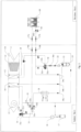
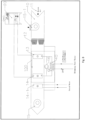
- FIG. 1 is a schematic view of the overall structure of a control system for adjusting air temperature, humidity and water temperature by an outdoor air heat exchanger according to the present invention, which comprises an indoor unit and an outdoor unit.
- the indoor unit comprises an air conditioning apparatus 10, which comprises an air recovery apparatus 11, an air filter 12, an air refrigerating and dehumidifying apparatus 13, an air reheating apparatus 14, an air supply apparatus 15 and a compressor unit.
- the compressor unit comprises a compressor 16 and an air-liquid separator 17 connected to the compressor 16.
- the indoor unit further comprises a water heat exchange apparatus 18 and a liquid storage tank 19.
- the outdoor unit comprises an outdoor air heat exchanger 20.
- the indoor unit further comprises a first three-way valve 31, a second three-way valve 32 and a four-way valve 33, the compressor 16 is connected to an inlet 31a of the first three-way valve, and an outlet 31b of the first three-way valve is connected to an inlet of the air reheating apparatus 14; an outlet 2 31c of the first three-way valve is connected to an inlet 33a of the four-way valve, and the four-way valve 33 comprises a first outlet 33b, a second outlet 33c and a third outlet 33d in turn.
- the first outlet 33b of the four-way valve is connected to a first indoor ball valve 36a.
- the first indoor ball valve 36a is connected to a first outdoor ball valve 37a, and the first outdoor ball valve 37a is connected to an outdoor air heat exchanger 20.
- the second outlet 33c of the four-way valve is connected to an air-liquid separator 17.
- the air-liquid separator 17 is connected to a compressor 16.
- the compressor 16 is connected to the inlet 31a of the first three-way valve.
- the third outlet 33d of the four-way valve is connected to a water heat exchange apparatus 18.
- the other end of the water heat exchange apparatus 18 is connected to a liquid storage tank 19 via a first check valve 34a.
- the other end of the air reheating apparatus 14 is connected to the liquid storage tank 19 via a second check valve 34b.
- the other end of the outdoor air heat exchanger is connected to a first expansion valve 38 and a fourth check valve 34d, which are connected to each other in parallel and then is connected to a second outdoor ball valve 37b.
- the second outdoor ball valve 37b is connected to a second indoor ball valve 36b.
- the second indoor ball valve 36b is connected to a third check valve 34c.
- the third check valve 34c is connected to a liquid storage tank 19.
- the liquid storage tank 19 is connected to an inlet 32a of a second three-way valve 32a.
- An outlet 1 32b of the second three-way valve is connected to a second expansion valve 39.
- the second expansion valve 39 is connected to an inlet of an air refrigerating and dehumidifying apparatus 13.
- An outlet of the air refrigerating and dehumidifying apparatus13 is connected to an air-liquid separator 17.
- the air-liquid separator 17 is connected to a compressor 16.
- the air refrigerating and dehumidifying apparatus 13 may further be connected to an inlet of an air reheating apparatus 14 via a valve 35.
- An outlet 2 32c of the second three-way valve is connected to a second indoor ball valve 36b.
- the second indoor ball valve 36b is connected to a second outdoor ball valve 37b.
- the second outdoor ball valve 37b is connected to a first expansion valve 38 and a fourth check valve 34d, which are connected to each other in parallel.
- the first expansion valve 38 and the fourth check valve 34d in parallel are connected to an outdoor air heat exchanger 20.
- a refrigerant filter 21, a sight glass 22 and a third indoor ball valve 36c are arranged between the liquid storage tank 19 and the second three-way valve 32.
- the control system is enabled when indoor humidity is lower than a set value, i.e.: when indoor humidity is lower than a set value, and air temperature and/or room temperature is lower than a set value, a heat absorption mode of the outdoor air heat exchanger will be enabled, refrigerant in an outdoor air heat exchanger is inputted to a four-way valve via an outdoor air heat exchanger and then to a compressor via the four-way valve, and converted into a heating medium inside the compressor.
- the heating medium is inputted to an inlet of a first three-way valve and to an air reheating apparatus via the first three-way valve and/or to a water heat exchange apparatus connected to a four-way valve; after heat exchange the heating medium flows back to a liquid storage tank via the air reheating apparatus and/or the water heat exchange apparatus, and then flows to the outdoor air heat exchanger via a second three-way valve.
- a heat dissipation mode of the outdoor air heat exchanger 20 When indoor humidity is lower than a set value, and water temperature and/or room temperature is higher than a set value, a heat dissipation mode of the outdoor air heat exchanger 20 will be enabled, the refrigerant in the outdoor air heat exchanger will circulate clockwise into an air heat exchanger 20, for heat dissipation by outdoor air.
- the refrigerant liquid after heat dissipation is collected to a liquid storage tank 19, and then reduces room temperature and/or water temperature through an air refrigerating and dehumidifying apparatus 13 and/or a water heat exchange apparatus 18.
- the control system is enabled when indoor humidity is higher than a set value, i.e.: when indoor humidity is higher than a set value and water temperature and/or room temperature is lower than a set value, a mode of dehumidifying heat pump will be enabled, refrigerant liquid will be collected to a liquid storage tank 19 and then perform refrigeration and dehumidification through an expansion valve 39 and an air refrigerating and dehumidifying apparatus 13.
- the refrigerant air after heat absorption is inputted to a compressor unit. After compression, the refrigerant air inside the compressor 16 is converted into a heating medium.
- the heating medium is inputted to a heat exchange apparatus and raises room temperature and/or water temperature through an air reheating apparatus 14 and/or a water heat exchange apparatus 18.
- a mode of dehumidifying heat pump When indoor humidity is higher than a set value, and water temperature and/or room temperature is higher than a set value, a mode of dehumidifying heat pump will be enabled, refrigerant liquid will be collected to a liquid storage tank 19 and then perform refrigeration and dehumidification through an expansion valve 39 and an air refrigerating and dehumidifying apparatus 13.
- the refrigerant air after heat absorption is inputted to a compressor unit. After compression, the refrigerant air inside the compressor 16 is converted into a heating medium.
- a heat dissipation mode of the outdoor air heat exchanger is enabled, and the refrigerant in the outdoor air heat exchanger circulates clockwise into an air heat exchanger 20, for heat dissipation by outdoor air.
- the operational logic is to open (open/close) valves for reverse circulation and turn an outdoor air heat exchanger into a "heat pump” to absorb outdoor heat to heat indoor air and water.
- the control logic of "heat pump” operation is shown in the table below:
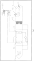
- FIG. 2 shows an embodiment of the present invention, comprising an air conditioning apparatus 10 and an outdoor air heat exchanger 20.
- the air conditioning apparatus 10 comprises an air recovery apparatus 11, an air filter 12, an air refrigerating and dehumidifying apparatus 13, an air reheating apparatus 14, an air supply apparatus 15 and an inlet-end outdoor exhaust fan 15-1.
- the air refrigerating and dehumidifying apparatus 13 and the air reheating apparatus 14 are connected to a compressor 16 in series to form a refrigerant system 100.
- an outdoor air heat exchanger 20 serves as a heat reject and heat absorption component.
- refrigerant in the outdoor air heat exchanger When indoor humidity is lower than a set value, refrigerant in the outdoor air heat exchanger will be inputted to a compressor unit via the outdoor air heat exchanger, and converted into a heating medium inside the compressor unit, and the heating medium will be inputted to a heat exchange apparatus, and adjust temperature through the air reheating apparatus 14.
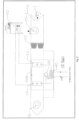
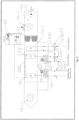
- FIG. 3 shows another embodiment of the present invention.
- a second heat exchanger 40 is connected to the refrigerant system in parallel, which may be a condenser, and exchanges heat with indoor water systems, such as swimming pool water and bath water.
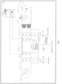
- FIG. 4 shows another embodiment of the present invention. Different from the embodiment disclosed in FIG. 3 , in this embodiment a second heat exchanger 40 is connected to the refrigerant system in parallel and connected to a water tower 50, for energy storage and heat dissipation.
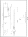
- FIG. 5 and FIG. 6 show another two embodiments of the present invention.
- the air conditioning apparatus is provided with a water cooling system 13-1 before air treatment of the refrigerant system, as shown in FIG. 5 , or a water cooling system 13-1 is added after air treatment of the refrigerant system and before air supply, and the water cooling system 13-1 is a refrigerating coil, and chilled water is delivered into the refrigerating coil to cool the air.
- FIG. 7 shows another embodiment of the present invention.
- the air conditioning apparatus is provided with a water cooling system 13-1 before air treatment of the refrigerant system, and is provided with a water heating system 14-1 after air treatment of the refrigerant system and before air supply.
- the water heating system 14-1 is a hot water coil and may be communicable to hot water for heating to raise temperature of the air.
- FIG. 8 shows another embodiment of the present invention. Different from the embodiment disclosed in FIG. 7 , in this embodiment the air conditioning apparatus is provided with a water heating system 14-1 after air treatment of the refrigerant system and before air supply.
- FIG. 9 shows another embodiment of the present invention.
- the second heat exchanger 40 is connected in series to a third heat exchanger 60 and used to heat swimming pool water.
- the third heat exchanger 60 is communicable to chilled water.
- the air conditioning apparatus is provided with a water cooling system 13-1 before air treatment of the refrigerant system.
- a third three-way valve 23 is arranged at an inlet of the water cooling system 13-1.
- An inlet 23a of the third three-way valve 23 is communicable to chilled water.
- An outlet 1 23b of the third three-way valve is connected to a refrigerating coil of the water cooling system 13-1.
- An outlet 2 23c of the third three-way valve is connected to an inlet of a third heat exchanger 60.
- a fourth three-way valve 24 is arranged at the inlet of the third heat exchanger 60, the outlet 2 23c of the third three-way valve is connected to an inlet 24a of the fourth three-way valve, or an outlet of the refrigerating coil of the water cooling system 13-1 is connected to the inlet 24a of the fourth three-way valve, an outlet 1 24b of the fourth three-way valve is connected to the inlet of the third heat exchanger 60, and an outlet 2 24c of the fourth three-way valve is communicable to chilled water.
- FIG. 10 shows another embodiment of the present invention.
- a first heat exchanger in a refrigerant system 100 is not the air reheating apparatus 14 in the air conditioning apparatus in the foregoing embodiments, but a separate condenser.
- the condenser When indoor air meets the conditions for dehumidification and cooling, the condenser will reject heat to a gas reheating apparatus 14 connected to the condenser.
- a heat absorption mode of an outdoor air heat exchanger 20 When indoor air does not meet the conditions for dehumidification and cooling, for example, the indoor humidity is lower than a set value in winter, a heat absorption mode of an outdoor air heat exchanger 20 will be enabled, refrigerant in the outdoor air heat exchanger will be inputted to a compressor unit via the outdoor air heat exchanger, and converted into a heating medium in the compressor unit, the heating medium will be inputted to a second heat exchanger 40, and the second heat exchanger 40 will exchange heat with an air reheating apparatus 14 or a water heat exchange apparatus 18 to adjust room temperature and water temperature.
- indoor refrigerant systems connected in parallel to an outdoor air heat exchanger.
- the indoor refrigerant system will perform dehumidification and cooling and use absorbed heat to adjust indoor air and indoor water systems (e.g., swimming pool or bath water), and when indoor humidity, temperature and pool water temperature all meet requirements, surplus heat recovered in a dehumidifying process will be removed through an outdoor air heat exchanger.
- indoor air and indoor water systems e.g., swimming pool or bath water
- surplus heat recovered in a dehumidifying process will be removed through an outdoor air heat exchanger.
- recovered latent heat is restricted.
- a "reverse circulation" system runs a refrigerant loop as an air source heat pump, providing enough heat for reheating of air and reheating of pool water.
- the outdoor air heat exchanger acts as a "heat pump” and absorbs outdoor heat to heat indoor air and water.
- the generated latent heat (from the reverse circulation system) subsequently is transferred to an air reheater and used to heat the hall and water of the swimming pool.
- the use of a reverse circulation system saves operating cost in winter by more than 60% in winter than an auxiliary electric heating device does.
Landscapes
- Engineering & Computer Science (AREA)
- Mechanical Engineering (AREA)
- General Engineering & Computer Science (AREA)
- Chemical & Material Sciences (AREA)
- Combustion & Propulsion (AREA)
- Physics & Mathematics (AREA)
- Thermal Sciences (AREA)
- Life Sciences & Earth Sciences (AREA)
- Sustainable Development (AREA)
- Air Conditioning Control Device (AREA)
- Central Air Conditioning (AREA)
Claims (8)
- Steuerungssystem zum Anpassen von Lufttemperatur, Feuchtigkeit und Wassertemperatur durch einen Außenluft-Wärmetauscher (20), wobei das System eine Klimaanlage (10), eine Wärmeaustauschvorrichtung und den Außenluft-Wärmetauscher (20) umfasst, wobeidie Klimaanlage (10) der Reihe nach Folgendes umfasst: eine Luftrückgewinnungsvorrichtung (11), eine Luftkühlungs- und -entfeuchtungsvorrichtung (13), eine Luftzuführungsvorrichtung (15) und eine Verdichtereinheit,die Luftkühlungs- und -entfeuchtungsvorrichtung (13) und die Verdichtereinheit in Reihe mit der Wärmeaustauschvorrichtung verbunden sind, um ein Kältemittelsystem (100) zu bilden,der Außenluft-Wärmetauscher (20) parallel mit dem Kältemittelsystem (100) verbunden ist,das Steuerungssystem dafür konfiguriert ist, aktiviert zu werden, wenn die Innenfeuchtigkeit niedriger ist als ein Sollwert, d. h.:wenn die Innenfeuchtigkeit niedriger ist als ein Sollwert und eine Wassertemperatur und/oder eine Raumtemperatur niedriger sind als ein Sollwert, ein Wärmeabsorptionsmodus des Außenluft-Wärmetauschers (20) aktiviert werden wird, ein Kältemittel in dem Außenluft-Wärmetauscher (20) über den Außenluft-Wärmetauscher (20) der Verdichtereinheit zugeführt werden wird, das Kältemittel in der Verdichtereinheit in ein Heizmedium umgewandelt werden kann und das Heizmedium der Wärmeaustauschvorrichtung zugeführt werden und durch die erste Wärmeaustauschvorrichtung die Wassertemperatur und/oder die Raumtemperatur erhöhen kann und,wenn die Innenfeuchtigkeit niedriger ist als ein Sollwert und die Wassertemperatur und/oder die Raumtemperatur höher sind als ein Sollwert, ein Wärmeableitungsmodus des Außenluft-Wärmetauschers (20) aktiviert werden wird, das Kältemittel in dem Außenluft-Wärmetauscher (20) eine Wärmeableitung durch Außenluft durchführen wird und das Kältemittel nach der Wärmeableitung der Wärmeaustauschvorrichtung zugeführt werden wird, um über die Wärmeaustauschvorrichtung die Wassertemperatur und/oder die Raumtemperatur zu verringern,dadurch gekennzeichnet, dassdas System derart konfiguriert ist, dass, wenn die Innenfeuchtigkeit höher ist als ein Sollwert und die Wassertemperatur und/oder die Raumtemperatur niedriger sind als ein Sollwert, ein Modus einer entfeuchtenden Wärmepumpe aktiviert werden wird, so dass das Kältemittel über die Luftkühlungs- und - entfeuchtungsvorrichtung (13) Wärme absorbieren und danach einer Verdichtereinheit zugeführt und in der Verdichtereinheit zu einem Heizmedium umgewandelt werden wird und das Heizmedium einer Wärmeaustauschvorrichtung zugeführt werden und über eine erste Wärmeaustauschvorrichtung die Wassertemperatur und/oder die Raumtemperatur erhöhen wird,wenn die Innenfeuchtigkeit höher ist als ein Sollwert und die Wassertemperatur und/oder die Raumtemperatur höher sind als ein Sollwert, ein Modus einer entfeuchtenden Wärmepumpe aktiviert werden wird, das Kältemittel die Wassertemperatur und/oder die Raumtemperatur über die Wärmeaustauschvorrichtung, die ein erster Wärmetauscher (18) und/oder die Luftkühlungs- und -entfeuchtungsvorrichtung (13) sein kann, verringern wird, das Kältemittel nach der Wärmeabsorption einer Verdichtereinheit zugeführt werden wird, das Kältemittel in der Verdichtereinheit zu einem Heizmedium umgewandelt werden wird und das Heizmedium zur Wärmeableitung durch Außenluft dem Außenluft-Wärmetauscher (20) zugeführt werden wird.
- Steuerungssystem zum Anpassen von Lufttemperatur, Feuchtigkeit und Wassertemperatur durch einen Außenluft-Wärmetauscher (20) nach Anspruch 1, wobeider erste Wärmetauscher (18) die Luftnachheizungsvorrichtung (14) ist, die innerhalb einer Klimaanlage (10) angeordnet ist, unddas Kältemittelsystem (100) parallel mit einem zweiten Wärmetauscher (40) verbunden ist, der mit einem Wassersystem oder einem Wasserturm (50) verbunden ist.
- Steuerungssystem zum Anpassen von Lufttemperatur, Feuchtigkeit und Wassertemperatur durch einen Außenluft-Wärmetauscher (20) nach Anspruch 2, wobeidas Steuerungssystem ferner ein erstes Dreiwegeventil, ein zweites Dreiwegeventil, ein Vierwegeventil und einen Flüssigkeitsspeichertank (19) umfasst,die Verdichtereinheit mit einem Einlass (23a, 24a, 31a, 32a, 33a) des ersten Dreiwegeventils verbunden ist und ein Auslass 1 des ersten Dreiwegeventils mit einem Einlass (23a, 24a, 31a, 32a, 33a) der Gasnachheizungsvorrichtung (14) verbunden ist, ein Auslass 2 des ersten Dreiwegeventils mit einem Einlass (23a, 24a, 31a, 32a, 33a) des Vierwegeventils verbunden ist und das Vierwegeventil der Reihe nach einen ersten Auslass (33b), einen zweiten Auslass (33c) und einen dritten Auslass (33d) umfasst,der erste Auslass (33b) des Vierwegeventils mit einem Außenluft-Wärmetauscher (20) verbunden ist, der zweite Auslass (33c) des Vierwegeventils mit einem Verdichter verbunden ist und der dritte Auslass (33d) des Vierwegeventils mit dem ersten Wärmetauscher (18) verbunden ist, der eine Wasser-Wärmetauschvorrichtung ist,die anderen Enden des Außenluft-Wärmetauschers (20), der Luftnachheizungsvorrichtung (14) beziehungsweise des zweiten Wärmetauschers (40) jeweils mit dem Flüssigkeitsspeichertank (19) verbunden sind,der Flüssigkeitsspeichertank (19) mit einem Einlass (23a, 24a, 31a, 32a, 33a) des zweiten Dreiwegventils verbunden ist, ein Auslass 1 des zweiten Dreiwegeventils mit einem zweiten Expansionsventil (39) verbunden ist, das zweite Expansionsventil (39) mit einem Einlass (23a, 24a, 31a, 32a, 33a) der Luftkühlungs- und -entfeuchtungsvorrichtung (13) verbunden ist, ein Auslass der Luftkühlungs- und - entfeuchtungsvorrichtung (13) mit einer Verdichtereinheit verbunden ist oder die Luftkühlungs- und -entfeuchtungsvorrichtung (13) über ein Ventil mit der Luftnachheizungsvorrichtung (14) verbunden ist und ein Auslass 2 des zweiten Dreiwegeventils mit einem ersten Expansionsventil (38) verbunden ist und das erste Expansionsventil (38) mit einem Außenluft-Wärmetauscher (20) verbunden ist,ein Wärmeabsorptionsmodus des Außenluft-Wärmetauschers (20) aktiviert wird, Kältemittel in dem Außenluft-Wärmetauscher (20) über den Außenluft-Wärmetauscher (20) dem Vierwegeventil, danach über das Vierwegeventil der Verdichtereinheit zugeführt und in der Verdichtereinheit zu einem Heizmedium umgewandelt wird und das Heizmedium einem Einlass (23a, 24a, 31a, 32a, 33a) des ersten Dreiwegeventils und der Luftnachheizungsvorrichtung (14) über das erste Dreiwegeventil und/oder dem zweiten Wärmetauscher (40), der mit dem Vierwegeventil verbunden ist, zugeführt wird, das Heizmedium nach dem Wärmeaustausch über die Luftnachheizungsvorrichtung (14) und/oder den zweiten Wärmetauscher (40) zurück zu dem Flüssigkeitsspeichertank (19) strömt und danach über das zweite Dreiwegeventil zu dem Außenluft-Wärmetauscher (20) strömt.
- Steuerungssystem zum Anpassen von Lufttemperatur, Feuchtigkeit und Wassertemperatur durch einen Außenluft-Wärmetauscher (20) nach einem der Ansprüche 1 bis 3, wobei die Klimaanlage (10) dafür konfiguriert ist, mit einem Wasserkühlungssystem (13-1) vor oder nach der Luftbehandlung des Kältemittelsystems (100) versehen zu werden.
- Steuerungssystem zum Anpassen von Lufttemperatur, Feuchtigkeit und Wassertemperatur durch einen Außenluft-Wärmetauscher (20) nach einem der Ansprüche 1 bis 3, wobei die Klimaanlage (10) dafür konfiguriert ist, mit einem Wasserheizungssystem (14-1) vor oder nach der Luftbehandlung des Kältemittelsystems (100) versehen zu werden.
- Steuerungssystem zum Anpassen von Lufttemperatur, Feuchtigkeit und Wassertemperatur durch einen Außenluft-Wärmetauscher (20) nach einem der Ansprüche 1 bis 3, wobei die Klimaanlage (10) dafür konfiguriert ist, mit einem Wasserkühlungssystem (13-1) vor der Luftbehandlung des Kältemittelsystems (100) versehen zu werden, und dafür konfiguriert ist, mit einem Wasserheizungssystem (14-1) nach der Luftbehandlung des Kältemittelsystems (100) versehen zu werden.
- Steuerungssystem zum Anpassen von Lufttemperatur, Feuchtigkeit und Wassertemperatur durch einen Außenluft-Wärmetauscher (20) nach einem der Ansprüche 1 bis 3, wobei der zweite Wärmetauscher (40) in Reihe mit einem dritten Wärmetauscher (60) verbunden ist und der dritte Wärmetauscher (60) mit gekühltem Wasser verbunden ist.
- Steuerungssystem zum Anpassen von Lufttemperatur, Feuchtigkeit und Wassertemperatur durch einen Außenluft-Wärmetauscher (20) nach Anspruch 7, wobei die Klimaanlage (10) dafür konfiguriert ist, mit einem Wasserkühlungssystem (13-1) vor der Luftbehandlung des Kältemittelsystems (100) versehen zu werden, ein drittes Dreiwegeventil dafür konfiguriert ist, an einem Einlass (23a, 24a, 31a, 32a, 33a) des Wasserkühlungssystems (13-1) angeordnet zu werden, und ein Auslass 2 des dritten Dreiwegeventils dafür konfiguriert ist, mit einem Einlass (23a, 24a, 31a, 32a, 33a) eines dritten Wärmetauschers (60) verbunden zu werden, ein viertes Dreiwegeventil dafür konfiguriert ist, an dem Einlass (23a, 24a, 31a, 32a, 33a) des dritten Wärmetauschers (60) bereitgestellt zu werden, der Auslass 2 des dritten Dreiwegeventils dafür konfiguriert ist, mit einem Einlass (23a, 24a, 31a, 32a, 33a) des vierten Dreiwegeventils verbunden zu werden, und ein Auslass 2 des vierten Dreiwegeventils dafür konfiguriert ist, mit gekühltem Wasser verbunden zu werden.
Applications Claiming Priority (1)
| Application Number | Priority Date | Filing Date | Title |
|---|---|---|---|
| HK19122058.1A HK1258422A2 (en) | 2019-04-09 | A control system for regulating air temperature, humidity and water temperature using outdoor air heat exchanger |
Publications (2)
| Publication Number | Publication Date |
|---|---|
| EP3722689A1 EP3722689A1 (de) | 2020-10-14 |
| EP3722689B1 true EP3722689B1 (de) | 2025-04-16 |
Family
ID=71251312
Family Applications (1)
| Application Number | Title | Priority Date | Filing Date |
|---|---|---|---|
| EP19185986.7A Active EP3722689B1 (de) | 2019-04-09 | 2019-07-12 | Steuerungssystem zur anpassung der lufttemperatur, feuchtigkeit und wassertemperatur durch einen aussenluftwärmetauscher |
Country Status (4)
| Country | Link |
|---|---|
| EP (1) | EP3722689B1 (de) |
| CN (2) | CN111795427A (de) |
| MY (1) | MY209160A (de) |
| SG (1) | SG10202002664QA (de) |
Families Citing this family (4)
| Publication number | Priority date | Publication date | Assignee | Title |
|---|---|---|---|---|
| CN114427759A (zh) * | 2020-10-29 | 2022-05-03 | 广东爱克节能设备有限公司 | 一种多功能泳池热泵除湿恒温系统 |
| CN113218098B (zh) * | 2021-04-01 | 2022-05-10 | 湖南雅立科技开发有限公司 | 一种基于三器冷媒压缩循环的气体处理方法和系统 |
| CN116557993A (zh) * | 2023-05-19 | 2023-08-08 | 广州万二二麦工程技术有限公司 | 一种外换热器结构互补风路合并的空调热水器主机融合体 |
| CN119802727B (zh) * | 2025-02-25 | 2025-09-19 | 湖南省湘能舒适环境科技有限责任公司 | 一种多级热湿交换的新风空调及控制方法 |
Citations (1)
| Publication number | Priority date | Publication date | Assignee | Title |
|---|---|---|---|---|
| EP3282211A1 (de) * | 2015-04-07 | 2018-02-14 | Daikin Industries, Ltd. | Klimaanlagensystem und steuerungsverfahren dafür |
Family Cites Families (15)
| Publication number | Priority date | Publication date | Assignee | Title |
|---|---|---|---|---|
| CN2457532Y (zh) * | 2000-12-28 | 2001-10-31 | 北京森博苑科技有限公司 | 具有生活热水的风冷热泵装置 |
| JP2010151380A (ja) * | 2008-12-25 | 2010-07-08 | Tokyo Electric Power Co Inc:The | 空気調和機 |
| CN101957097A (zh) * | 2010-09-15 | 2011-01-26 | 江苏天舒电器有限公司 | 一种热回收型多功能泳池一体机 |
| JP5518812B2 (ja) * | 2011-09-06 | 2014-06-11 | 木村工機株式会社 | 空調機能付外調機 |
| JP6129520B2 (ja) * | 2012-11-16 | 2017-05-17 | 三菱重工業株式会社 | マルチ型空気調和機及びマルチ型空気調和機の制御方法 |
| CN204494893U (zh) * | 2015-01-15 | 2015-07-22 | 佛山市顺德区资乐电器有限公司 | 一种恒温热泵泳池机 |
| CN106152264B (zh) * | 2015-04-07 | 2019-10-11 | 大金工业株式会社 | 空调系统及其控制方法 |
| EP3415839A4 (de) * | 2016-02-10 | 2019-01-30 | Mitsubishi Electric Corporation | Kältekreislaufvorrichtung |
| JP2017142039A (ja) * | 2016-02-12 | 2017-08-17 | 三菱重工サーマルシステムズ株式会社 | 空気調和装置 |
| EP3299734B1 (de) * | 2016-09-23 | 2024-03-06 | Daikin Industries, Ltd. | System für klimaanlage und warmwasserversorgung |
| CN206410291U (zh) * | 2016-12-30 | 2017-08-15 | 江苏天舒电器股份有限公司 | 一种变风量泳池变频除湿兼池水恒温的设备 |
| CN107747806B (zh) * | 2017-10-27 | 2020-08-14 | 国安瑞(北京)科技有限公司 | 空调系统 |
| CN108332327B (zh) * | 2018-03-01 | 2023-11-10 | 清华大学 | 一种空气处理设备 |
| CN208382429U (zh) * | 2018-04-28 | 2019-01-15 | 江苏三六五室内环境科技有限公司 | 一种自带冷热水循环供应的新风机 |
| CN208282328U (zh) * | 2018-05-18 | 2018-12-25 | 浙江欧伦电气有限公司 | 一体式水冷泳池热泵除湿系统 |
-
2019
- 2019-07-04 CN CN201910600693.0A patent/CN111795427A/zh active Pending
- 2019-07-04 CN CN201921040127.0U patent/CN210832212U/zh active Active
- 2019-07-12 EP EP19185986.7A patent/EP3722689B1/de active Active
-
2020
- 2020-03-23 SG SG10202002664QA patent/SG10202002664QA/en unknown
- 2020-03-31 MY MYPI2020001650A patent/MY209160A/en unknown
Patent Citations (1)
| Publication number | Priority date | Publication date | Assignee | Title |
|---|---|---|---|---|
| EP3282211A1 (de) * | 2015-04-07 | 2018-02-14 | Daikin Industries, Ltd. | Klimaanlagensystem und steuerungsverfahren dafür |
Also Published As
| Publication number | Publication date |
|---|---|
| CN210832212U (zh) | 2020-06-23 |
| CN111795427A (zh) | 2020-10-20 |
| EP3722689A1 (de) | 2020-10-14 |
| SG10202002664QA (en) | 2020-11-27 |
| MY209160A (en) | 2025-06-24 |
Similar Documents
| Publication | Publication Date | Title |
|---|---|---|
| EP3722689B1 (de) | Steuerungssystem zur anpassung der lufttemperatur, feuchtigkeit und wassertemperatur durch einen aussenluftwärmetauscher | |
| CN101701737B (zh) | 一种热泵驱动的溶液除湿空调装置 | |
| US20190154281A1 (en) | Control systems for liquid desiccant air conditioning systems | |
| US10941948B2 (en) | Tank system for liquid desiccant air conditioning system | |
| AU2010231401B2 (en) | Dehumidification system | |
| US10101043B2 (en) | HVAC system and method of operation | |
| JP2010002162A (ja) | 空気調和設備 | |
| CN103090484B (zh) | 一种温湿度独立控制空调系统及其使用方法 | |
| US9920963B1 (en) | System for conditioning air with temperature and humidity control and heat utilization | |
| EP3704414A1 (de) | Verfahren und systeme für klimatisierung mit flüssigem trockenmittel | |
| Liang et al. | Low-grade energy-bus air conditioning system using energy efficient three-fluid heat exchange terminals | |
| JP2006292313A (ja) | 地中熱利用装置 | |
| CN205332368U (zh) | 一种自由冷却机房空调机组 | |
| CN108443960A (zh) | 一种带新风功能的多联式空调机组 | |
| CN103712291A (zh) | 可制备冷或热媒并同时处理空气热湿负荷的空调装置 | |
| CN104566719A (zh) | 一种防冻型的空调装置 | |
| CN211822929U (zh) | 热泵机组 | |
| CN204534915U (zh) | 一种防冻型的空调装置 | |
| CN115218310B (zh) | 一种基于单机双蒸发热泵机组的温湿分控多工况空调系统 | |
| JP5451995B2 (ja) | 空気調和設備 | |
| CN213630742U (zh) | 全联供热泵除湿热水机组 | |
| CN205227904U (zh) | 集空气源热泵和新风处理于一体且无需除霜的装置 | |
| HK40038222A (en) | Control system for adjusting air temperature, humidity and water temperature by an outdoor air heat exchanger | |
| CN114754518B (zh) | 一种夏季室内辐射式供冷系统及其控制方法 | |
| KR102857368B1 (ko) | 에너지 절감형 공기조화장치 |
Legal Events
| Date | Code | Title | Description |
|---|---|---|---|
| PUAI | Public reference made under article 153(3) epc to a published international application that has entered the european phase |
Free format text: ORIGINAL CODE: 0009012 |
|
| STAA | Information on the status of an ep patent application or granted ep patent |
Free format text: STATUS: REQUEST FOR EXAMINATION WAS MADE |
|
| 17P | Request for examination filed |
Effective date: 20190712 |
|
| AK | Designated contracting states |
Kind code of ref document: A1 Designated state(s): AL AT BE BG CH CY CZ DE DK EE ES FI FR GB GR HR HU IE IS IT LI LT LU LV MC MK MT NL NO PL PT RO RS SE SI SK SM TR |
|
| AX | Request for extension of the european patent |
Extension state: BA ME |
|
| STAA | Information on the status of an ep patent application or granted ep patent |
Free format text: STATUS: EXAMINATION IS IN PROGRESS |
|
| 17Q | First examination report despatched |
Effective date: 20230206 |
|
| GRAP | Despatch of communication of intention to grant a patent |
Free format text: ORIGINAL CODE: EPIDOSNIGR1 |
|
| STAA | Information on the status of an ep patent application or granted ep patent |
Free format text: STATUS: GRANT OF PATENT IS INTENDED |
|
| RIC1 | Information provided on ipc code assigned before grant |
Ipc: F24F 110/20 20180101ALN20241125BHEP Ipc: F24F 110/10 20180101ALN20241125BHEP Ipc: F24F 11/83 20180101ALI20241125BHEP Ipc: F24F 11/46 20180101AFI20241125BHEP |
|
| INTG | Intention to grant announced |
Effective date: 20241210 |
|
| RIC1 | Information provided on ipc code assigned before grant |
Ipc: F24F 110/20 20180101ALN20241129BHEP Ipc: F24F 110/10 20180101ALN20241129BHEP Ipc: F24F 11/83 20180101ALI20241129BHEP Ipc: F24F 11/46 20180101AFI20241129BHEP |
|
| GRAS | Grant fee paid |
Free format text: ORIGINAL CODE: EPIDOSNIGR3 |
|
| GRAA | (expected) grant |
Free format text: ORIGINAL CODE: 0009210 |
|
| STAA | Information on the status of an ep patent application or granted ep patent |
Free format text: STATUS: THE PATENT HAS BEEN GRANTED |
|
| AK | Designated contracting states |
Kind code of ref document: B1 Designated state(s): AL AT BE BG CH CY CZ DE DK EE ES FI FR GB GR HR HU IE IS IT LI LT LU LV MC MK MT NL NO PL PT RO RS SE SI SK SM TR |
|
| REG | Reference to a national code |
Ref country code: GB Ref legal event code: FG4D |
|
| REG | Reference to a national code |
Ref country code: CH Ref legal event code: EP Ref country code: DE Ref legal event code: R096 Ref document number: 602019068621 Country of ref document: DE |
|
| REG | Reference to a national code |
Ref country code: IE Ref legal event code: FG4D |
|
| REG | Reference to a national code |
Ref country code: NL Ref legal event code: MP Effective date: 20250416 |
|
| PG25 | Lapsed in a contracting state [announced via postgrant information from national office to epo] |
Ref country code: NL Free format text: LAPSE BECAUSE OF FAILURE TO SUBMIT A TRANSLATION OF THE DESCRIPTION OR TO PAY THE FEE WITHIN THE PRESCRIBED TIME-LIMIT Effective date: 20250416 |
|
| REG | Reference to a national code |
Ref country code: AT Ref legal event code: MK05 Ref document number: 1785918 Country of ref document: AT Kind code of ref document: T Effective date: 20250416 |
|
| PG25 | Lapsed in a contracting state [announced via postgrant information from national office to epo] |
Ref country code: FI Free format text: LAPSE BECAUSE OF FAILURE TO SUBMIT A TRANSLATION OF THE DESCRIPTION OR TO PAY THE FEE WITHIN THE PRESCRIBED TIME-LIMIT Effective date: 20250416 Ref country code: PT Free format text: LAPSE BECAUSE OF FAILURE TO SUBMIT A TRANSLATION OF THE DESCRIPTION OR TO PAY THE FEE WITHIN THE PRESCRIBED TIME-LIMIT Effective date: 20250818 Ref country code: ES Free format text: LAPSE BECAUSE OF FAILURE TO SUBMIT A TRANSLATION OF THE DESCRIPTION OR TO PAY THE FEE WITHIN THE PRESCRIBED TIME-LIMIT Effective date: 20250416 |
|
| REG | Reference to a national code |
Ref country code: LT Ref legal event code: MG9D |
|
| PG25 | Lapsed in a contracting state [announced via postgrant information from national office to epo] |
Ref country code: GR Free format text: LAPSE BECAUSE OF FAILURE TO SUBMIT A TRANSLATION OF THE DESCRIPTION OR TO PAY THE FEE WITHIN THE PRESCRIBED TIME-LIMIT Effective date: 20250717 Ref country code: NO Free format text: LAPSE BECAUSE OF FAILURE TO SUBMIT A TRANSLATION OF THE DESCRIPTION OR TO PAY THE FEE WITHIN THE PRESCRIBED TIME-LIMIT Effective date: 20250716 |
|
| PG25 | Lapsed in a contracting state [announced via postgrant information from national office to epo] |
Ref country code: PL Free format text: LAPSE BECAUSE OF FAILURE TO SUBMIT A TRANSLATION OF THE DESCRIPTION OR TO PAY THE FEE WITHIN THE PRESCRIBED TIME-LIMIT Effective date: 20250416 |
|
| PG25 | Lapsed in a contracting state [announced via postgrant information from national office to epo] |
Ref country code: BG Free format text: LAPSE BECAUSE OF FAILURE TO SUBMIT A TRANSLATION OF THE DESCRIPTION OR TO PAY THE FEE WITHIN THE PRESCRIBED TIME-LIMIT Effective date: 20250416 |
|
| PG25 | Lapsed in a contracting state [announced via postgrant information from national office to epo] |
Ref country code: HR Free format text: LAPSE BECAUSE OF FAILURE TO SUBMIT A TRANSLATION OF THE DESCRIPTION OR TO PAY THE FEE WITHIN THE PRESCRIBED TIME-LIMIT Effective date: 20250416 |
|
| PG25 | Lapsed in a contracting state [announced via postgrant information from national office to epo] |
Ref country code: AT Free format text: LAPSE BECAUSE OF FAILURE TO SUBMIT A TRANSLATION OF THE DESCRIPTION OR TO PAY THE FEE WITHIN THE PRESCRIBED TIME-LIMIT Effective date: 20250416 |
|
| PG25 | Lapsed in a contracting state [announced via postgrant information from national office to epo] |
Ref country code: RS Free format text: LAPSE BECAUSE OF FAILURE TO SUBMIT A TRANSLATION OF THE DESCRIPTION OR TO PAY THE FEE WITHIN THE PRESCRIBED TIME-LIMIT Effective date: 20250716 |
|
| PG25 | Lapsed in a contracting state [announced via postgrant information from national office to epo] |
Ref country code: IS Free format text: LAPSE BECAUSE OF FAILURE TO SUBMIT A TRANSLATION OF THE DESCRIPTION OR TO PAY THE FEE WITHIN THE PRESCRIBED TIME-LIMIT Effective date: 20250816 |
|
| PG25 | Lapsed in a contracting state [announced via postgrant information from national office to epo] |
Ref country code: LV Free format text: LAPSE BECAUSE OF FAILURE TO SUBMIT A TRANSLATION OF THE DESCRIPTION OR TO PAY THE FEE WITHIN THE PRESCRIBED TIME-LIMIT Effective date: 20250416 |
|
| PGFP | Annual fee paid to national office [announced via postgrant information from national office to epo] |
Ref country code: GB Payment date: 20251003 Year of fee payment: 7 |
|
| PG25 | Lapsed in a contracting state [announced via postgrant information from national office to epo] |
Ref country code: SM Free format text: LAPSE BECAUSE OF FAILURE TO SUBMIT A TRANSLATION OF THE DESCRIPTION OR TO PAY THE FEE WITHIN THE PRESCRIBED TIME-LIMIT Effective date: 20250416 Ref country code: DK Free format text: LAPSE BECAUSE OF FAILURE TO SUBMIT A TRANSLATION OF THE DESCRIPTION OR TO PAY THE FEE WITHIN THE PRESCRIBED TIME-LIMIT Effective date: 20250416 |
|
| PGFP | Annual fee paid to national office [announced via postgrant information from national office to epo] |
Ref country code: FR Payment date: 20251210 Year of fee payment: 7 |
|
| REG | Reference to a national code |
Ref country code: DE Ref legal event code: R097 Ref document number: 602019068621 Country of ref document: DE |
|
| PG25 | Lapsed in a contracting state [announced via postgrant information from national office to epo] |
Ref country code: CZ Free format text: LAPSE BECAUSE OF FAILURE TO SUBMIT A TRANSLATION OF THE DESCRIPTION OR TO PAY THE FEE WITHIN THE PRESCRIBED TIME-LIMIT Effective date: 20250416 |
|
| PG25 | Lapsed in a contracting state [announced via postgrant information from national office to epo] |
Ref country code: EE Free format text: LAPSE BECAUSE OF FAILURE TO SUBMIT A TRANSLATION OF THE DESCRIPTION OR TO PAY THE FEE WITHIN THE PRESCRIBED TIME-LIMIT Effective date: 20250416 |
|
| PG25 | Lapsed in a contracting state [announced via postgrant information from national office to epo] |
Ref country code: SK Free format text: LAPSE BECAUSE OF FAILURE TO SUBMIT A TRANSLATION OF THE DESCRIPTION OR TO PAY THE FEE WITHIN THE PRESCRIBED TIME-LIMIT Effective date: 20250416 Ref country code: RO Free format text: LAPSE BECAUSE OF FAILURE TO SUBMIT A TRANSLATION OF THE DESCRIPTION OR TO PAY THE FEE WITHIN THE PRESCRIBED TIME-LIMIT Effective date: 20250416 |
|
| PG25 | Lapsed in a contracting state [announced via postgrant information from national office to epo] |
Ref country code: IT Free format text: LAPSE BECAUSE OF FAILURE TO SUBMIT A TRANSLATION OF THE DESCRIPTION OR TO PAY THE FEE WITHIN THE PRESCRIBED TIME-LIMIT Effective date: 20250416 |
|
| PLBE | No opposition filed within time limit |
Free format text: ORIGINAL CODE: 0009261 |
|
| STAA | Information on the status of an ep patent application or granted ep patent |
Free format text: STATUS: NO OPPOSITION FILED WITHIN TIME LIMIT |
|
| REG | Reference to a national code |
Ref country code: CH Ref legal event code: H13 Free format text: ST27 STATUS EVENT CODE: U-0-0-H10-H13 (AS PROVIDED BY THE NATIONAL OFFICE) Effective date: 20260224 |
|
| REG | Reference to a national code |
Ref country code: CH Ref legal event code: L10 Free format text: ST27 STATUS EVENT CODE: U-0-0-L10-L00 (AS PROVIDED BY THE NATIONAL OFFICE) Effective date: 20260225 |
|
| PG25 | Lapsed in a contracting state [announced via postgrant information from national office to epo] |
Ref country code: LU Free format text: LAPSE BECAUSE OF NON-PAYMENT OF DUE FEES Effective date: 20250712 |
|
| 26N | No opposition filed |
Effective date: 20260119 |
|
| REG | Reference to a national code |
Ref country code: BE Ref legal event code: MM Effective date: 20250731 |
|
| PGFP | Annual fee paid to national office [announced via postgrant information from national office to epo] |
Ref country code: DE Payment date: 20251210 Year of fee payment: 7 |
|
| PG25 | Lapsed in a contracting state [announced via postgrant information from national office to epo] |
Ref country code: BE Free format text: LAPSE BECAUSE OF NON-PAYMENT OF DUE FEES Effective date: 20250731 |
|
| PG25 | Lapsed in a contracting state [announced via postgrant information from national office to epo] |
Ref country code: CH Free format text: LAPSE BECAUSE OF NON-PAYMENT OF DUE FEES Effective date: 20250731 |