EP3722718A1 - Ziegelauskleidungsverfahren - Google Patents
Ziegelauskleidungsverfahren Download PDFInfo
- Publication number
- EP3722718A1 EP3722718A1 EP18886028.2A EP18886028A EP3722718A1 EP 3722718 A1 EP3722718 A1 EP 3722718A1 EP 18886028 A EP18886028 A EP 18886028A EP 3722718 A1 EP3722718 A1 EP 3722718A1
- Authority
- EP
- European Patent Office
- Prior art keywords
- bricks
- brick
- terms
- lining
- tier
- Prior art date
- Legal status (The legal status is an assumption and is not a legal conclusion. Google has not performed a legal analysis and makes no representation as to the accuracy of the status listed.)
- Pending
Links
- 239000011449 brick Substances 0.000 title claims abstract description 289
- 238000000034 method Methods 0.000 title claims abstract description 49
- 230000002093 peripheral effect Effects 0.000 claims abstract description 13
- 239000000203 mixture Substances 0.000 claims description 18
- 238000004519 manufacturing process Methods 0.000 abstract description 12
- 238000000465 moulding Methods 0.000 description 39
- 230000000052 comparative effect Effects 0.000 description 30
- 238000012856 packing Methods 0.000 description 30
- 239000002184 metal Substances 0.000 description 27
- 239000011819 refractory material Substances 0.000 description 5
- 238000010586 diagram Methods 0.000 description 2
- 230000000694 effects Effects 0.000 description 2
- 238000010438 heat treatment Methods 0.000 description 2
- 239000000463 material Substances 0.000 description 2
- 238000001035 drying Methods 0.000 description 1
- 238000004898 kneading Methods 0.000 description 1
- 238000003825 pressing Methods 0.000 description 1
- 238000009849 vacuum degassing Methods 0.000 description 1
Images

Classifications
-
- C—CHEMISTRY; METALLURGY
- C21—METALLURGY OF IRON
- C21B—MANUFACTURE OF IRON OR STEEL
- C21B7/00—Blast furnaces
- C21B7/04—Blast furnaces with special refractories
- C21B7/06—Linings for furnaces
-
- F—MECHANICAL ENGINEERING; LIGHTING; HEATING; WEAPONS; BLASTING
- F27—FURNACES; KILNS; OVENS; RETORTS
- F27D—DETAILS OR ACCESSORIES OF FURNACES, KILNS, OVENS OR RETORTS, IN SO FAR AS THEY ARE OF KINDS OCCURRING IN MORE THAN ONE KIND OF FURNACE
- F27D1/00—Casings; Linings; Walls; Roofs
- F27D1/04—Casings; Linings; Walls; Roofs characterised by the form, e.g. shape of the bricks or blocks used
-
- C—CHEMISTRY; METALLURGY
- C21—METALLURGY OF IRON
- C21C—PROCESSING OF PIG-IRON, e.g. REFINING, MANUFACTURE OF WROUGHT-IRON OR STEEL; TREATMENT IN MOLTEN STATE OF FERROUS ALLOYS
- C21C5/00—Manufacture of carbon-steel, e.g. plain mild steel, medium carbon steel or cast steel or stainless steel
- C21C5/28—Manufacture of steel in the converter
- C21C5/42—Constructional features of converters
- C21C5/44—Refractory linings
-
- F—MECHANICAL ENGINEERING; LIGHTING; HEATING; WEAPONS; BLASTING
- F27—FURNACES; KILNS; OVENS; RETORTS
- F27D—DETAILS OR ACCESSORIES OF FURNACES, KILNS, OVENS OR RETORTS, IN SO FAR AS THEY ARE OF KINDS OCCURRING IN MORE THAN ONE KIND OF FURNACE
- F27D1/00—Casings; Linings; Walls; Roofs
- F27D1/04—Casings; Linings; Walls; Roofs characterised by the form, e.g. shape of the bricks or blocks used
- F27D1/045—Bricks for lining cylindrical bodies, e.g. skids, tubes
-
- F—MECHANICAL ENGINEERING; LIGHTING; HEATING; WEAPONS; BLASTING
- F27—FURNACES; KILNS; OVENS; RETORTS
- F27D—DETAILS OR ACCESSORIES OF FURNACES, KILNS, OVENS OR RETORTS, IN SO FAR AS THEY ARE OF KINDS OCCURRING IN MORE THAN ONE KIND OF FURNACE
- F27D1/00—Casings; Linings; Walls; Roofs
- F27D1/16—Making or repairing linings ; Increasing the durability of linings; Breaking away linings
Definitions
- the present invention relates to a method for forming a brick lining to construct a hollow approximately cylindrical-shaped sidewall (inner sidewall) of a kiln/furnace, such as a blast furnace, an air heating furnace (hot blast stove), a converter, an electric furnace, a ladle, or a vacuum degassing furnace.
- a kiln/furnace such as a blast furnace, an air heating furnace (hot blast stove), a converter, an electric furnace, a ladle, or a vacuum degassing furnace.
- a sidewall of a converter is typically constructed by sequentially arranging a plurality of bricks on an inner surface of a peripheral portion of the converter in a circumferential direction of the peripheral portion to form a tier of bricks, and stacking a plurality of the tiers of bricks along the peripheral portion in an upward-downward direction.
- Each of the bricks has a key (crown) shape or a similar shape thereto.
- each of the bricks has two circumferentially opposed side faces formed to define a tapered shape in a radially inward direction when view in the upward-downward direction.
- two types of bricks shaped differently in terms of taper angle have been used for lining each of a plurality of tier regions of the inner surface of the peripheral portion each corresponding to a respective one of the tiers of bricks.
- This method of combining the two types of bricks shaped differently in terms of the taper angle can also be applied to any of other kilns/furnaces slightly different in terms of inner diameter.
- the above method requires preliminarily determining a combination (ratio) between the two types of differently-shaped bricks, and selecting one of the two types of differently-shaped bricks such that the selected brick is oriented in a direction more closely perpendicular to the peripheral portion than the other brick, in each circumferential region, thereby leading to a problem that brick lining forming work becomes complicated and requires time and effort.
- Patent Document 1 JP 2005-009707A
- a technical problem to be solved by the present invention is to provide a method for forming a brick lining to construct a sidewall of a kiln/furnace, while improving efficiency of brick lining forming work without causing any increase in manufacturing cost of bricks to be used.
- the present invention provides a brick lining forming method having features described in the following sections 1 to 4.
- each of the two or more tier regions different in terms of the pre-lining radius by using bricks identical in terms of the taper angle, the height dimension and the length dimension, it becomes possible to manufacture bricks shaped differently (in terms of back face width), while suppressing a manufacturing cost (molding cost) of the bricks.
- each of the bricks is molded while pressure is applied to a mixture in a direction allowing a pressure-receiving part of the mixture to be formed as at least one of the circumferential side faces.
- bricks different in terms of the back face width can be molded by adjusting the amount of mixture to be used, without exchanging any liners used as upper and lower pressure-applying surfaces, so that it is possible to suppress the manufacturing cost.
- the lining can be formed by continuously using basically identically-shaped bricks, so that it is possible to significantly improve efficiency of brick lining forming work. Additionally, there is no need to preliminarily arrange bricks in a given order, so that there is no concern about an increase in burden of packing work.
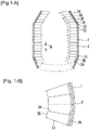
- FIG. 1A is a vertical sectional view schematically showing a converter to explain a brick lining forming method according to one embodiment of the present invention.
- FIG. 1A is a partial cross-sectional view of a 7th tier of bricks in a brick lining of a side wall of the converter illustrated in FIG. 1A . It should be noted here that illustration of bricks of a furnace bottom is omitted in FIG. 1A .
- a lining of a permanent refractory material 2 is formed on an inner surface of a shell 1 to form a peripheral portion, and a lining of a plurality of bricks 3A to 3H as a lining material is formed on an inner surface of the permanent refractory material 2 to construct a sidewall of the converter.
- a lining of a plurality of bricks 3A to 3H as a lining material is formed on an inner surface of the permanent refractory material 2 to construct a sidewall of the converter.
- eighteen tiers of bricks is stacked (to form a lining), wherein all bricks used in the lining are identical in terms of after-mentioned taper angle, so that the number of bricks used in each of the tiers is the same. Further, all bricks used in the eighteen tiers are also identical in terms of length dimension.
- this converter is formed such that it is cross-sectionally circular at any position, wherein, in cross-section, bricks are arranged as shown in FIG. 1B .
- the term "circumferential side faces" of each brick means circumferentially opposed side faces 33, 34 of each of the bricks in a state in which a kiln/furnace is lined with the bricks, as shown in FIG. 1B .
- a straight barrel part whose inner surface consists of 3rd to 13th tier regions corresponding to 3rd to 13th tiers of bricks is constant in terms of pre-lining radius, whereas a remaining part whose inner surface consists of 1st, 2nd and 14th to 18th tier regions corresponding to 1st, 2nd and 14th to 18th tiers of bricks varies in terms of the pre-lining radius.
- pre-lining radius means a distance between a central axis of the converter and the inner surface of the permanent refractory material.
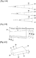
- FIG. 2A is top plan views showing, respectively, the brick 3A to be used in the 1st tier region, the brick 3B to be used in the 2nd tier region, and the brick 3C to be used in each of the 3rd to 13th tier regions. All the bricks 3A to 3C are identical in terms of taper angle a.
- tape angle of each brick means an angle ⁇ between the two circumferential side faces 33, 34.
- FIG. 2A is a top plan view showing a state in which three types of bricks 3A to 3C to be used, respectively, in the 1st tier, the 2nd tier, and each of the 3rd to 13th tiers are superimposed on each other in their height direction, while the respective circumferential side faces 34 of the superimposed bricks 3A to 3C are arranged to be flush with each other.
- the undermost brick 3C is used in each of the 3rd to 13th tiers, i.e., disposed on the tier region having the largest pre-lining radius, so that it is largest in terms of after-mentioned back face width, among the bricks 3Ato 3C.
- the back face width becomes smaller as the pre-lining radius becomes smaller.
- the back face width W3 of the brick 3C > the back face width W2 of the brick 3B (for the 2nd tier) > the back face width W1 of the brick 3A (for the 1st tier).
- FIG. 2C is a perspective view of the brick 3C to be used in each of the 3rd to 13th tiers.
- the brick 3C is formed in a so-called key (crown) shape, wherein each of two opposed side faces (circumferential side faces) extends in a length direction of the brick 3C obliquely at the same inclination angle to define trapezoidal (key)-shaped upper and lower faces each having the largest area.
- key row
- FIG. 2C is a perspective view of the brick 3C to be used in each of the 3rd to 13th tiers.
- the brick 3C is formed in a so-called key (crown) shape, wherein each of two opposed side faces (circumferential side faces) extends in a length direction of the brick 3C obliquely at the same inclination angle to define trapezoidal (key)-shaped upper and lower faces each having the largest area.
- 1st and 2nd tiers bricks different in terms of width dimension are used.
- a circumferential dimension of a back face 36 of the brick and a circumferential dimension of an inner face 35 of the brick are defined, respectively, as a back face width and an inner face width
- a face 32 of the brick on the side of the bottom of the kiln/furnace and a face 31 of the brick on the side of the top of the kiln/furnace are defined, respectively, as a lower face and an upper face.
- a dimension of the brick in a length direction of the kiln/furnace is defined as a height dimension H
- a dimension of the brick in a radial direction of the kiln/furnace is defined as a length dimension L.
- the three types of bricks 3A to 3C are identical in terms of the taper angle a, the height dimension H and the length dimension L.
- each of the bricks is molded while pressure is uniaxially applied to a mixture in a manner allowing a pressure-receiving part of the mixture to be formed as one 34 of the circumferential side faces, as shown in FIG. 2B , so that it is possible to mold the three types of bricks using a common set of a metal frame and a vertical liner.
- the metal frame means a frame for forming the side of a brick during molding
- the vertical liner means a pair of upper and lower liners for forming the top and bottom of the brick during molding.
- the upper liner and/or the lower liner are configured to be moved within the metal frame in the upward-downward direction, thereby compressing a mixture to form the mixture into a brick shape. Further, the amount of mixture to be put in a space defined by the metal frame and the lower liner can be changed to mold a plurality of types of bricks different only in terms of the width dimension.
- FIG. 3A is a top plan view showing a state in which the brick 3D to be used in the 14th tier, the brick 3E to be used in the 15th tier and the brick 3F to be used in the 16th tier are superimposed on each other in their height direction, while the respective circumferential side faces 34 of the superimposed bricks 3D to 3F are arranged to be flush with each other.
- the undermost brick 3D is used in the 14th tier, i.e., disposed on the tier region having a relatively large pre-lining radius, so that it is relatively large in terms of the back face width.
- the back face width becomes smaller as the pre-lining radius becomes smaller.
- the brick 3G to be used in the 17th tier and the brick 3H to be used in the 18th tier become smaller in terms of the back face width in this order, although not shown in FIG. 3A . That is, the back face width W4 of the brick 3D (for the 14th tier) > the back face width W5 of the brick 3E (for the 15th tier) > the back face width W6 of the brick 3F (for the 16th tier) > the back face width of the brick 3G (for the 17th tier) > the back face width of the brick 3H (for the 18th tier).
- FIG. 3B is a perspective view of the brick 3E to be used in the 14th tier, wherein, differently from the brick illustrated in FIG. 2C , each of the inner face 35 and the back face 36 are inclined with respect to the upper face 31, and these two faces (inner and back faces 35, 36) extend parallel to each other. Bricks each having a width dimension different from that of this brick 3E is used in the 14th to 18th tiers.
- the bricks to be used in the respective tiers are molded to be identical in terms of the taper angle a, the height dimension H and the length dimension L even though the corresponding tier regions are different in terms of the pre-lining radius, so that it is possible to form these bricks into desired shapes, using a common set of a metal frame and a vertical liner, as mentioned above.
- a common set of a metal frame and a vertical liner as mentioned above.
- there is no need for exchange work of molding dies (the metal frame and the vertical liner) during molding and there is no concern about an increase in molding cost (manufacturing cost) even if the number of brick shapes increases.
- upper and lower parts of the peripheral portion is inwardly inclined (narrowed) as shown in FIG. 1A , so that there are a plurality of tier regions different in terms of the pre-lining radius. In this situation, the application of the present invention makes it possible to significantly effectively improve efficiency of lining work without causing any increase in manufacturing cost.
- each of the tier regions identical in terms of the pre-lining radius, i.e., the 3rd to 13th tier regions identically-shaped bricks can be used, so that it is possible to improve efficiency of the lining work without causing any increase in cost of packing work
- all bricks for a lining to be formed on one tier region are formed equally in terms of the length dimension.
- bricks different in terms of the length dimension may be partly used, as long as they are identical in terms of the taper angle.
- the brick lining forming method of the present invention may be applied to such a tier region.
- a 900 mm-length brick is used in the tier region which is likely to undergo severe wear damage, and each of the remaining tier regions is lined with two types of bricks: the 900 mm-length brick; and 800 mm-length brick. That is, the point of the brick lining forming method of the present invention is in that "only bricks identical in terms of the taper angle and the height dimension are used, except for an adjustment brick, in each of the two or more tier regions different in terms of the pre-lining radius, wherein bricks identical in terms of the taper angle, the height dimension and length dimension, and different in terms of the back face width, are used in at least a part of each of the two or more tier regions", i.e., the bricks identical in terms of the taper angle, the height dimension and length dimension may be used in "at least part" of each of the two or more tier regions.
- the bricks identical in terms of the taper angle, the height dimension and length dimension may be used in "at least part" of each of the two or more tier regions different in terms of the pre-lining radius.
- FIG. 1A shows a case where the bricks identical in terms of the taper angle, the height dimension and length dimension are used in "each" of the two or more tier regions different in terms of the pre-lining radius.
- the efficiency of the lining work is most improved.
- the brick identical in terms of the taper angle, the height dimension and length dimension is used in 50% (one-half) or more of each of the two or more tier regions.
- the number of brick shapes per tier in the conventional brick lining forming method is four, whereas the number of brick shapes per tier in the present invention is only two.
- FIG. 1A shows an example in which the present invention is applied to a sidewall of one converter, wherein the sidewall has two or more tier regions different in terms of the pre-lining radius.
- the present invention can also be applied to a case where respective sidewalls of plural types of converters and other kilns/furnaces different in terms of the pre-lining radius are lined.
- the same set of molding dies (a metal frame and a vertical liner) can be used for a plurality of kilns/furnaces, so that it is possible to line the peripheral portion of the sidewall of each of the kilns/furnaces without causing any increase in manufacturing cost.
- plural types of bricks shaped differently in terms of the inner face width and the back face width can be molded by uniaxially applying pressure to a mixture in manner allowing a pressure-receiving part of the mixture to be formed as at least one of the circumferential side faces, using one set of the metal frame and the vertical liner, while adjusting the amount of the mixture to be put inside the metal frame.
- manufacturing steps other than molding i.e., kneading, drying, heat treatment and the like, can be conducted in the same manner as before.
- a key shape and a similar shape thereto are shown as brick shape.
- an arch shape and a wedge shape may be used.
- FIG. 4 is a vertical sectional view schematically showing an actual converter subjected to a lining test.
- 1st to 36th tier regions were lined by the brick lining forming method of the present invention, and 37th to n-th tier regions (n is an integer of 37 or more) was lined one-by-one with a combination of two types of conventional bricks shaped differently in terms of the taper angle. It should be noted here that any lining on tier regions other than those lined by the brick lining forming method of the present invention is omitted in FIG. 4 .
- the 7th to 36th tier regions form an inner surface of a straight barrel part having a pre-lining radius of 4000 mm, and a part thereof below the 6th tier regions is reduced in the pre-lining radius.
- a brick having a length dimension of 720 mm was used in the 1st to 5th tier regions. Further, a brick having a length dimension of 810 mm was used in the 6th to 17th tier regions, and a brick having a length dimension of 900 mm was used in the 18th to 36th tier regions. Further, all bricks had a taper angle of 2.25°, and a height dimension of 150 mm.
- the back face width of the brick in the straight barrel part (the 7th to 36th tier regions) was set to 157 mm, and the back face width of the brick in the tier region having a relatively small pre-lining radius was set to be less than that of the brick in the straight barrel part.
- Table 1 shows a brick shape, a packing method, a molding method and workloads of various works, in the inventive example, in such a manner as to compare them with those in a comparative example.
- the comparative example is a conventional brick lining forming method in which two types of bricks shaped differently in terms of the taper angle are used in each tier region. Further, each of the bricks used in the inventive and comparative examples was molded under the condition that a pressure-receiving part (a contact part with a vertical liner) of a mixture is formed as the circumferential side faces.
- each of the workloads of various works is expressed as an index calculated on the assumption that a respective one of the workloads of various works in the comparative example is 100.
- each tier was different in terms of the back face width and the inner face width.
- the packing method only identically-shaped bricks were packed in one pallet. Further, during molding, the amount of mixture to be put in a metal frame was changed to change the width dimension. Therefore, only a set of one type of metal frame and one type of vertical liner was used for all bricks.
- the two types of bricks shaped differently only in terms of the taper angle were used.
- the packing method the two types of differently-shaped bricks were arranged and packed in one pallet in a given order according to which the bricks are laid in a converter. Further, during molding, two types of vertical liners were used to change the taper angle.
- the total number of brick shapes in the inventive example, it was five because each of the 1st to 5th tiers was different in terms of the width dimension.
- the comparative example it was two, wherein the two brick shapes were different in terms of the taper angle.
- bricks can be molded using one type of vertical liner, because the bricks are identical in terms of the length dimension and the taper angle, whereas the comparative example requires using two types of vertical liners to change the taper angle, so that it is necessary to additionally perform vertical liner exchange work, resulting in an increase in workload of the molding work.
- each of the two tiers was different in terms of the back face width and the inner face width.
- the packing method only identically-shaped bricks are packed in one pallet. These bricks are different from the bricks in the 1st to 5th tiers in terms of the length dimension.
- a set of a metal frame and a vertical liner having a length dimension greater than that of the set for the bricks in the 1st to 5th tiers was used.
- the width dimension was changed by changing the amount of mixture to be put in a metal frame. Therefore, only a set of one type of metal frame and one type of vertical liner was used for all bricks.
- the two types of bricks shaped differently only in terms of the taper angle were used.
- the packing method the two types of differently-shaped bricks were arranged and packed in one pallet in a given order according to which the bricks are laid in a converter. Further, during molding, a set of a metal frame and a vertical liner having a length dimension different from that of the set for the bricks in the 1st to 5th tiers was used, and, differently from the inventive example, two types of vertical liners were used to change the taper angle.
- the total number of brick shapes in the inventive example, it was two because each of the 6th and 7th tiers was different in terms of the width dimension.
- the comparative example it was two, wherein the two brick shapes were different in terms of the taper angle.
- the inventive example requires work for exchanging the set of the metal frame and the vertical liner, because the bricks are different from those in the 1st to 5th tiers in terms of the length dimension, whereas the comparative example further requires using two types of vertical liners, so that it is necessary to additionally perform vertical liner exchange work, resulting in an increase in workload of the molding work.
- the inventive example it is only necessary to pack identically-shaped bricks in one pallet, whereas, in the comparative example, it is necessary to arrange two types of differently-shaped bricks in one pallet in a given order, resulting in an increase in workload of the packing work.
- the same brick as that in the 7th tier was used, wherein, as the packing method, identically-shaped bricks were packed in one pallet, and a set of one type of metal frame and one type of vertical liner was used for all bricks.
- the two types of bricks shaped differently in terms of the taper angle were used as with the bricks in the 7th tier.
- the packing method the two types of differently-shaped bricks were arranged and packed in one pallet in a given order according to which the bricks are laid in a converter. Further, during molding, two types of vertical liners were used to change the taper angle.
- both the inventive example and the comparative example do not require metal frame exchange work, because the same brick as that in the 7th tier can be used in each of the examples.
- the comparative example requires using two types of vertical liners to change the taper angle, so that it is necessary to additionally perform vertical liner exchange work, resulting in an increase in workload of the molding work.
- the inventive example it is only necessary to pack identically-shaped bricks in one pallet, whereas, in the comparative example, it is necessary to arrange two types of differently-shaped bricks in one pallet in a given order, resulting in a significant increase in workload of the packing work.
- identically-shaped bricks were used, wherein, as the packing method, the identically-shaped bricks were packed in one pallet.
- the bricks are different from those in the 7th to 17th tiers in terms of the length dimension.
- a set of a metal frame and a vertical liner having a length dimension greater than that of the set for the bricks in the 7st to 17th tiers was used,
- the two types of bricks shaped differently in terms of the taper angle were used.
- the packing method the two types of differently-shaped bricks were arranged and packed in one pallet in a given order according to which the bricks are laid in a converter. Further, during molding, a set of a metal frame and a vertical liner having a length dimension greater than that of the set for the bricks in the 7th to 17th tiers was used, and two types of vertical liners were used to mold bricks different in terms of the taper angle.
- the inventive example requires work for exchanging the set of the metal frame and the vertical liner used for the bricks in the 7th to 17th tiers for a set of a metal frame and a vertical liner having a longer length dimension.
- the comparative example further requires work for exchanging the two types of vertical liners to mold two types of bricks shaped differently in terms of the taper angle, so that the comparative example needs a larger workload of the molding work.
- the inventive example it is only necessary to pack identically-shaped bricks in one pallet, whereas, in the comparative example, it is necessary to arrange two types of differently-shaped bricks in one pallet in a given order, resulting in an increase in workload of the packing work.
- the inventive and comparative examples have been described without making mention of the use of an adjustment brick.
- the term "adjustment brick” means a brick which is produced by measuring the size of the gap and processing a brick material in conformity to the measured size, and is to be driven into the gap so as to fill the gap and prevent the laid bricks from being untightened in a circumferential direction.
- the adjustment brick is appropriately used.
- a workload caused by using the adjustment brick is approximately the same between the inventive and comparative examples.
- the use of the adjustment brick does not exert any influence on the aforementioned comparison between the workloads of the inventive and comparative examples.
- the 1st to 36th tier regions are lined by the brick lining forming method of the present invention, and the 37th to n-th tiers are lined by the conventional brick lining forming method. It is to be understood that the inventive example falls within the scape of the present invention as defined by the appended claims, as long as the 1st to 36th tier regions are lined by the brick lining forming method of the present invention.
Landscapes
- Engineering & Computer Science (AREA)
- Chemical & Material Sciences (AREA)
- Manufacturing & Machinery (AREA)
- Materials Engineering (AREA)
- Metallurgy (AREA)
- Organic Chemistry (AREA)
- Mechanical Engineering (AREA)
- General Engineering & Computer Science (AREA)
- Furnace Housings, Linings, Walls, And Ceilings (AREA)
- Carbon Steel Or Casting Steel Manufacturing (AREA)
- Blast Furnaces (AREA)
Applications Claiming Priority (2)
| Application Number | Priority Date | Filing Date | Title |
|---|---|---|---|
| JP2017234403A JP6310610B1 (ja) | 2017-12-06 | 2017-12-06 | れんがのライニング方法 |
| PCT/JP2018/042597 WO2019111683A1 (ja) | 2017-12-06 | 2018-11-19 | れんがのライニング方法 |
Publications (2)
| Publication Number | Publication Date |
|---|---|
| EP3722718A1 true EP3722718A1 (de) | 2020-10-14 |
| EP3722718A4 EP3722718A4 (de) | 2021-07-21 |
Family
ID=61901924
Family Applications (1)
| Application Number | Title | Priority Date | Filing Date |
|---|---|---|---|
| EP18886028.2A Pending EP3722718A4 (de) | 2017-12-06 | 2018-11-19 | Ziegelauskleidungsverfahren |
Country Status (9)
| Country | Link |
|---|---|
| US (1) | US11708617B2 (de) |
| EP (1) | EP3722718A4 (de) |
| JP (1) | JP6310610B1 (de) |
| CN (1) | CN111033162B (de) |
| AU (1) | AU2018381861B2 (de) |
| BR (1) | BR112020009148B1 (de) |
| CA (1) | CA3085900C (de) |
| TW (1) | TWI680270B (de) |
| WO (1) | WO2019111683A1 (de) |
Families Citing this family (2)
| Publication number | Priority date | Publication date | Assignee | Title |
|---|---|---|---|---|
| JP2024002223A (ja) * | 2022-06-23 | 2024-01-11 | 日本製鉄株式会社 | 内張りれんがの築造方法 |
| KR20250099953A (ko) | 2023-12-26 | 2025-07-03 | 주식회사 에스엔엔씨 | 전기로용 내화물 몰드 및 이를 이용한 내화물 시공방법 |
Family Cites Families (25)
| Publication number | Priority date | Publication date | Assignee | Title |
|---|---|---|---|---|
| US1123874A (en) * | 1914-02-20 | 1915-01-05 | Veitscher Magnesitwerke Ag | Furnace-wall. |
| US3272490A (en) * | 1963-09-25 | 1966-09-13 | Corhart Refractories Co | Steelmaking furnace |
| US3350085A (en) * | 1963-10-28 | 1967-10-31 | Detrick M H Co | Refractory lining for conical portion of a furnace and brick therefor |
| DE2306858C2 (de) * | 1973-02-12 | 1974-05-16 | Didier-Werke Ag, 6200 Wiesbaden | Ausmauerung für den Mündungsbereich von Konvertern |
| US4343459A (en) * | 1980-09-08 | 1982-08-10 | Dresser Industries, Inc. | Basic oxygen furnace construction |
| DE3342078C2 (de) * | 1983-09-14 | 1986-04-10 | Hubert Dipl.-Ing. 4500 Osnabrück Grospitsch | Oxygenstahl-Konverter bzw. Elektrostahl-Lichtbogenofen mit feuerfestem basischen Futter |
| US4920899A (en) * | 1989-06-02 | 1990-05-01 | American Telephone And Telegraph Company | Modular furnace and methods of repairing same |
| DE3940575A1 (de) * | 1989-12-08 | 1991-06-13 | Cra Services | Verfahren zur haltbarkeitssteigerung von feuerfesten gefaesszustellungen |
| AT405570B (de) * | 1992-01-31 | 1999-09-27 | Veitsch Radex Ag | System von formatsteinen zur ausmauerung von kalottenböden |
| JPH05306181A (ja) * | 1992-04-30 | 1993-11-19 | Nippon Steel Corp | 溶融金属容器用煉瓦 |
| JP2003231910A (ja) * | 2002-02-07 | 2003-08-19 | Jfe Steel Kk | 転炉絞り部のライニング |
| US6540510B1 (en) * | 2002-03-11 | 2003-04-01 | Weyerhaeuser Company | Hemispherical dome for refractory vessel |
| JP2004010936A (ja) * | 2002-06-05 | 2004-01-15 | Jfe Steel Kk | 転炉ライニング構造 |
| JP3948436B2 (ja) | 2003-06-17 | 2007-07-25 | 住友金属工業株式会社 | 煉瓦積み体の製造方法 |
| CN2641558Y (zh) * | 2003-06-27 | 2004-09-15 | 太原钢铁(集团)有限公司 | 一种氩氧炉炉型结构 |
| EP2365553A1 (de) | 2003-07-28 | 2011-09-14 | Kyocera Corporation | Mehrschichtiges piezoelektrisches Element |
| JP2005336515A (ja) * | 2004-05-24 | 2005-12-08 | Kurosaki Harima Corp | 転炉の大型炉口れんがとそれを用いた転炉の炉口のライニング構造 |
| EP1990429A1 (de) * | 2007-05-07 | 2008-11-12 | Paul Wurth Refractory & Engineering GmbH | Verfahren zum Bau eines Stützringes in einer kurvenförmigen Wand |
| CN101251335B (zh) * | 2008-04-01 | 2010-06-09 | 武汉钢铁(集团)公司 | 转炉炉衬的螺旋砌筑方法 |
| CN101381788B (zh) * | 2008-08-21 | 2010-04-07 | 武汉钢铁(集团)公司 | 用于大型转炉钢包内壁的等端差耐火砖及其砌筑方法 |
| LU91713B1 (en) * | 2010-07-27 | 2012-01-30 | Wurth Paul Sa | Hearth for a metallurgical furnace having an improved wall lining |
| CN103175401B (zh) * | 2011-12-26 | 2015-10-28 | 贵阳铝镁设计研究院有限公司 | 耐火砖砌体膨胀缝留设方法及砌体 |
| CN203464726U (zh) * | 2013-08-21 | 2014-03-05 | 辽宁中镁高温材料有限公司 | 用于砌筑球形炉底的双弧面环砖 |
| JP6221797B2 (ja) * | 2014-02-07 | 2017-11-01 | 新日鐵住金株式会社 | 窯炉および窯炉の築炉方法 |
| JP6452633B2 (ja) * | 2016-01-18 | 2019-01-16 | 東京窯業株式会社 | 焼成プレキャストブロック |
-
2017
- 2017-12-06 JP JP2017234403A patent/JP6310610B1/ja active Active
-
2018
- 2018-11-19 AU AU2018381861A patent/AU2018381861B2/en active Active
- 2018-11-19 CA CA3085900A patent/CA3085900C/en active Active
- 2018-11-19 US US16/768,852 patent/US11708617B2/en active Active
- 2018-11-19 EP EP18886028.2A patent/EP3722718A4/de active Pending
- 2018-11-19 CN CN201880052611.7A patent/CN111033162B/zh active Active
- 2018-11-19 BR BR112020009148-0A patent/BR112020009148B1/pt active IP Right Grant
- 2018-11-19 WO PCT/JP2018/042597 patent/WO2019111683A1/ja not_active Ceased
- 2018-11-27 TW TW107142164A patent/TWI680270B/zh active
Also Published As
| Publication number | Publication date |
|---|---|
| AU2018381861A1 (en) | 2020-07-09 |
| JP2019100664A (ja) | 2019-06-24 |
| TWI680270B (zh) | 2019-12-21 |
| JP6310610B1 (ja) | 2018-04-11 |
| CN111033162B (zh) | 2021-08-31 |
| BR112020009148A2 (pt) | 2020-10-27 |
| AU2018381861B2 (en) | 2021-05-06 |
| TW201934948A (zh) | 2019-09-01 |
| WO2019111683A1 (ja) | 2019-06-13 |
| US20210140002A1 (en) | 2021-05-13 |
| CN111033162A (zh) | 2020-04-17 |
| CA3085900C (en) | 2022-07-19 |
| BR112020009148B1 (pt) | 2023-01-31 |
| US11708617B2 (en) | 2023-07-25 |
| CA3085900A1 (en) | 2019-06-13 |
| EP3722718A4 (de) | 2021-07-21 |
Similar Documents
| Publication | Publication Date | Title |
|---|---|---|
| EP0832406B1 (de) | Stein fuer waermeaustauscher | |
| CA3085900C (en) | Brick lining forming method | |
| US7677007B2 (en) | Interlocking insulating firebrick | |
| EP2101134A1 (de) | Gitterbackstein | |
| JP6340780B2 (ja) | 六角レンガ用金型および六角レンガ成型方法 | |
| US20040140598A1 (en) | Lining of the cone of a converter | |
| KR101480874B1 (ko) | 고하중 장비 동선용 알루미늄 억세스 플로어 패널 | |
| WO2021173023A1 (en) | Checker-brick, construction method for a structure formed of a plurality of checker-bricks and the structure thereof | |
| JP7194062B2 (ja) | コークス炉用れんが積体及びその製造方法 | |
| JP2015148402A (ja) | 窯炉および窯炉の築炉方法 | |
| CN211770953U (zh) | 一种双膛石灰窑环形通道用砌砖 | |
| JP2009108363A (ja) | 炉の逆傾斜ライニング構造 | |
| JPH07224308A (ja) | 高炉羽口の耐火物構造 | |
| WO2007142632A1 (en) | Interlocking insulating firebrick | |
| JPS6137904A (ja) | 高炉炉体保護壁 | |
| JPS6335708A (ja) | 高炉炉体保護壁 | |
| US9170052B2 (en) | Lower vessel of RH degasser | |
| CN213771899U (zh) | 一种高耐震干熄焦斜道结构 | |
| CN110438275B (zh) | 一种高炉炉缸浇注方法及模具 | |
| JPS6031063Y2 (ja) | 高炉炉底コ−ナ−部構造 | |
| KR20260063546A (ko) | 진공 탈가스 설비용 침적관 및 이의 제조방법 | |
| CN118391909A (zh) | 一种新型环形炉以及炉底边缘砖 | |
| ITMI20011595A1 (it) | Forno a suola rotante di impiego siderurgico | |
| CN121571630A (zh) | 一种侧打成型钢包砖 | |
| KR100589435B1 (ko) | 전로의 내화물 2중 나선형 축조방법 |
Legal Events
| Date | Code | Title | Description |
|---|---|---|---|
| STAA | Information on the status of an ep patent application or granted ep patent |
Free format text: STATUS: THE INTERNATIONAL PUBLICATION HAS BEEN MADE |
|
| PUAI | Public reference made under article 153(3) epc to a published international application that has entered the european phase |
Free format text: ORIGINAL CODE: 0009012 |
|
| STAA | Information on the status of an ep patent application or granted ep patent |
Free format text: STATUS: REQUEST FOR EXAMINATION WAS MADE |
|
| 17P | Request for examination filed |
Effective date: 20200706 |
|
| AK | Designated contracting states |
Kind code of ref document: A1 Designated state(s): AL AT BE BG CH CY CZ DE DK EE ES FI FR GB GR HR HU IE IS IT LI LT LU LV MC MK MT NL NO PL PT RO RS SE SI SK SM TR |
|
| AX | Request for extension of the european patent |
Extension state: BA ME |
|
| DAV | Request for validation of the european patent (deleted) | ||
| DAX | Request for extension of the european patent (deleted) | ||
| A4 | Supplementary search report drawn up and despatched |
Effective date: 20210617 |
|
| RIC1 | Information provided on ipc code assigned before grant |
Ipc: F27D 1/16 20060101AFI20210611BHEP Ipc: C21C 5/44 20060101ALI20210611BHEP Ipc: F27D 1/00 20060101ALI20210611BHEP Ipc: C21B 7/06 20060101ALI20210611BHEP Ipc: F27B 1/14 20060101ALI20210611BHEP Ipc: F27B 14/08 20060101ALI20210611BHEP Ipc: F27B 14/10 20060101ALI20210611BHEP Ipc: F27D 1/04 20060101ALI20210611BHEP |
|
| STAA | Information on the status of an ep patent application or granted ep patent |
Free format text: STATUS: EXAMINATION IS IN PROGRESS |
|
| 17Q | First examination report despatched |
Effective date: 20220502 |