EP3722728A1 - Anordnung für eine latentwärmetauscherkammer - Google Patents
Anordnung für eine latentwärmetauscherkammer Download PDFInfo
- Publication number
- EP3722728A1 EP3722728A1 EP18887165.1A EP18887165A EP3722728A1 EP 3722728 A1 EP3722728 A1 EP 3722728A1 EP 18887165 A EP18887165 A EP 18887165A EP 3722728 A1 EP3722728 A1 EP 3722728A1
- Authority
- EP
- European Patent Office
- Prior art keywords
- liquid
- chamber
- latent heat
- microgrooves
- face
- Prior art date
- Legal status (The legal status is an assumption and is not a legal conclusion. Google has not performed a legal analysis and makes no representation as to the accuracy of the status listed.)
- Granted
Links
Images


Classifications
-
- F—MECHANICAL ENGINEERING; LIGHTING; HEATING; WEAPONS; BLASTING
- F28—HEAT EXCHANGE IN GENERAL
- F28D—HEAT-EXCHANGE APPARATUS, NOT PROVIDED FOR IN ANOTHER SUBCLASS, IN WHICH THE HEAT-EXCHANGE MEDIA DO NOT COME INTO DIRECT CONTACT
- F28D15/00—Heat-exchange apparatus with the intermediate heat-transfer medium in closed tubes passing into or through the conduit walls ; Heat-exchange apparatus employing intermediate heat-transfer medium or bodies
- F28D15/02—Heat-exchange apparatus with the intermediate heat-transfer medium in closed tubes passing into or through the conduit walls ; Heat-exchange apparatus employing intermediate heat-transfer medium or bodies in which the medium condenses and evaporates, e.g. heat pipes
- F28D15/04—Heat-exchange apparatus with the intermediate heat-transfer medium in closed tubes passing into or through the conduit walls ; Heat-exchange apparatus employing intermediate heat-transfer medium or bodies in which the medium condenses and evaporates, e.g. heat pipes with tubes having a capillary structure
- F28D15/046—Heat-exchange apparatus with the intermediate heat-transfer medium in closed tubes passing into or through the conduit walls ; Heat-exchange apparatus employing intermediate heat-transfer medium or bodies in which the medium condenses and evaporates, e.g. heat pipes with tubes having a capillary structure characterised by the material or the construction of the capillary structure
-
- B—PERFORMING OPERATIONS; TRANSPORTING
- B01—PHYSICAL OR CHEMICAL PROCESSES OR APPARATUS IN GENERAL
- B01D—SEPARATION
- B01D1/00—Evaporating
- B01D1/04—Evaporators with horizontal tubes
-
- B—PERFORMING OPERATIONS; TRANSPORTING
- B01—PHYSICAL OR CHEMICAL PROCESSES OR APPARATUS IN GENERAL
- B01D—SEPARATION
- B01D1/00—Evaporating
- B01D1/16—Evaporating by spraying
- B01D1/20—Sprayers
-
- B—PERFORMING OPERATIONS; TRANSPORTING
- B01—PHYSICAL OR CHEMICAL PROCESSES OR APPARATUS IN GENERAL
- B01D—SEPARATION
- B01D1/00—Evaporating
- B01D1/28—Evaporating with vapour compression
-
- B—PERFORMING OPERATIONS; TRANSPORTING
- B01—PHYSICAL OR CHEMICAL PROCESSES OR APPARATUS IN GENERAL
- B01D—SEPARATION
- B01D5/00—Condensation of vapours; Recovering volatile solvents by condensation
- B01D5/0003—Condensation of vapours; Recovering volatile solvents by condensation by using heat-exchange surfaces for indirect contact between gases or vapours and the cooling medium
-
- B—PERFORMING OPERATIONS; TRANSPORTING
- B01—PHYSICAL OR CHEMICAL PROCESSES OR APPARATUS IN GENERAL
- B01D—SEPARATION
- B01D5/00—Condensation of vapours; Recovering volatile solvents by condensation
- B01D5/0003—Condensation of vapours; Recovering volatile solvents by condensation by using heat-exchange surfaces for indirect contact between gases or vapours and the cooling medium
- B01D5/0009—Horizontal tubes
-
- B—PERFORMING OPERATIONS; TRANSPORTING
- B01—PHYSICAL OR CHEMICAL PROCESSES OR APPARATUS IN GENERAL
- B01D—SEPARATION
- B01D5/00—Condensation of vapours; Recovering volatile solvents by condensation
- B01D5/0057—Condensation of vapours; Recovering volatile solvents by condensation in combination with other processes
- B01D5/006—Condensation of vapours; Recovering volatile solvents by condensation in combination with other processes with evaporation or distillation
-
- B—PERFORMING OPERATIONS; TRANSPORTING
- B01—PHYSICAL OR CHEMICAL PROCESSES OR APPARATUS IN GENERAL
- B01D—SEPARATION
- B01D5/00—Condensation of vapours; Recovering volatile solvents by condensation
- B01D5/0057—Condensation of vapours; Recovering volatile solvents by condensation in combination with other processes
- B01D5/0075—Condensation of vapours; Recovering volatile solvents by condensation in combination with other processes with heat exchanging
-
- C—CHEMISTRY; METALLURGY
- C02—TREATMENT OF WATER, WASTE WATER, SEWAGE, OR SLUDGE
- C02F—TREATMENT OF WATER, WASTE WATER, SEWAGE, OR SLUDGE
- C02F1/00—Treatment of water, waste water, or sewage
- C02F1/02—Treatment of water, waste water, or sewage by heating
- C02F1/04—Treatment of water, waste water, or sewage by heating by distillation or evaporation
- C02F1/041—Treatment of water, waste water, or sewage by heating by distillation or evaporation by means of vapour compression
-
- C—CHEMISTRY; METALLURGY
- C02—TREATMENT OF WATER, WASTE WATER, SEWAGE, OR SLUDGE
- C02F—TREATMENT OF WATER, WASTE WATER, SEWAGE, OR SLUDGE
- C02F1/00—Treatment of water, waste water, or sewage
- C02F1/02—Treatment of water, waste water, or sewage by heating
- C02F1/04—Treatment of water, waste water, or sewage by heating by distillation or evaporation
- C02F1/048—Purification of waste water by evaporation
-
- F—MECHANICAL ENGINEERING; LIGHTING; HEATING; WEAPONS; BLASTING
- F28—HEAT EXCHANGE IN GENERAL
- F28D—HEAT-EXCHANGE APPARATUS, NOT PROVIDED FOR IN ANOTHER SUBCLASS, IN WHICH THE HEAT-EXCHANGE MEDIA DO NOT COME INTO DIRECT CONTACT
- F28D15/00—Heat-exchange apparatus with the intermediate heat-transfer medium in closed tubes passing into or through the conduit walls ; Heat-exchange apparatus employing intermediate heat-transfer medium or bodies
- F28D15/02—Heat-exchange apparatus with the intermediate heat-transfer medium in closed tubes passing into or through the conduit walls ; Heat-exchange apparatus employing intermediate heat-transfer medium or bodies in which the medium condenses and evaporates, e.g. heat pipes
- F28D15/0233—Heat-exchange apparatus with the intermediate heat-transfer medium in closed tubes passing into or through the conduit walls ; Heat-exchange apparatus employing intermediate heat-transfer medium or bodies in which the medium condenses and evaporates, e.g. heat pipes the conduits having a particular shape, e.g. non-circular cross-section, annular
-
- F—MECHANICAL ENGINEERING; LIGHTING; HEATING; WEAPONS; BLASTING
- F28—HEAT EXCHANGE IN GENERAL
- F28D—HEAT-EXCHANGE APPARATUS, NOT PROVIDED FOR IN ANOTHER SUBCLASS, IN WHICH THE HEAT-EXCHANGE MEDIA DO NOT COME INTO DIRECT CONTACT
- F28D20/00—Heat storage plants or apparatus in general; Regenerative heat-exchange apparatus not covered by groups F28D17/00 or F28D19/00
- F28D20/02—Heat storage plants or apparatus in general; Regenerative heat-exchange apparatus not covered by groups F28D17/00 or F28D19/00 using latent heat
-
- F—MECHANICAL ENGINEERING; LIGHTING; HEATING; WEAPONS; BLASTING
- F28—HEAT EXCHANGE IN GENERAL
- F28F—DETAILS OF HEAT-EXCHANGE AND HEAT-TRANSFER APPARATUS, OF GENERAL APPLICATION
- F28F13/00—Arrangements for modifying heat-transfer, e.g. increasing, decreasing
- F28F13/18—Arrangements for modifying heat-transfer, e.g. increasing, decreasing by applying coatings, e.g. radiation-absorbing, radiation-reflecting; by surface treatment, e.g. polishing
- F28F13/185—Heat-exchange surfaces provided with microstructures or with porous coatings
- F28F13/187—Heat-exchange surfaces provided with microstructures or with porous coatings especially adapted for evaporator surfaces or condenser surfaces, e.g. with nucleation sites
-
- C—CHEMISTRY; METALLURGY
- C02—TREATMENT OF WATER, WASTE WATER, SEWAGE, OR SLUDGE
- C02F—TREATMENT OF WATER, WASTE WATER, SEWAGE, OR SLUDGE
- C02F2103/00—Nature of the water, waste water, sewage or sludge to be treated
- C02F2103/08—Seawater, e.g. for desalination
-
- F—MECHANICAL ENGINEERING; LIGHTING; HEATING; WEAPONS; BLASTING
- F28—HEAT EXCHANGE IN GENERAL
- F28D—HEAT-EXCHANGE APPARATUS, NOT PROVIDED FOR IN ANOTHER SUBCLASS, IN WHICH THE HEAT-EXCHANGE MEDIA DO NOT COME INTO DIRECT CONTACT
- F28D21/00—Heat-exchange apparatus not covered by any of the groups F28D1/00 - F28D20/00
- F28D2021/0019—Other heat exchangers for particular applications; Heat exchange systems not otherwise provided for
- F28D2021/0061—Other heat exchangers for particular applications; Heat exchange systems not otherwise provided for for phase-change applications
- F28D2021/0066—Other heat exchangers for particular applications; Heat exchange systems not otherwise provided for for phase-change applications with combined condensation and evaporation
-
- Y—GENERAL TAGGING OF NEW TECHNOLOGICAL DEVELOPMENTS; GENERAL TAGGING OF CROSS-SECTIONAL TECHNOLOGIES SPANNING OVER SEVERAL SECTIONS OF THE IPC; TECHNICAL SUBJECTS COVERED BY FORMER USPC CROSS-REFERENCE ART COLLECTIONS [XRACs] AND DIGESTS
- Y02—TECHNOLOGIES OR APPLICATIONS FOR MITIGATION OR ADAPTATION AGAINST CLIMATE CHANGE
- Y02A—TECHNOLOGIES FOR ADAPTATION TO CLIMATE CHANGE
- Y02A20/00—Water conservation; Efficient water supply; Efficient water use
- Y02A20/124—Water desalination
-
- Y—GENERAL TAGGING OF NEW TECHNOLOGICAL DEVELOPMENTS; GENERAL TAGGING OF CROSS-SECTIONAL TECHNOLOGIES SPANNING OVER SEVERAL SECTIONS OF THE IPC; TECHNICAL SUBJECTS COVERED BY FORMER USPC CROSS-REFERENCE ART COLLECTIONS [XRACs] AND DIGESTS
- Y02—TECHNOLOGIES OR APPLICATIONS FOR MITIGATION OR ADAPTATION AGAINST CLIMATE CHANGE
- Y02E—REDUCTION OF GREENHOUSE GAS [GHG] EMISSIONS, RELATED TO ENERGY GENERATION, TRANSMISSION OR DISTRIBUTION
- Y02E60/00—Enabling technologies; Technologies with a potential or indirect contribution to GHG emissions mitigation
- Y02E60/14—Thermal energy storage
Definitions
- the present invention relates to an arrangement for a latent heat exchanger chamber, which comprises an evaporator on its inner face and a condenser on its outer face, applicable to distillation devices.
- the present invention seeks to increase the aggregate latent heat transfer coefficient and reduce the temperature differential or gradient between the condensing face and the evaporating face of a latent heat exchanger by means of an arrangement of a latent heat exchange chamber, as defined in the claims.
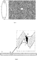
- FIG. 1 and 2 show an arrangement of a latent heat exchange chamber 1 condensing on its outer face and evaporating on its inner face.
- the outer face of the heat exchange chamber is covered 4, at least in part, with microgrooves or other capillary structure in which the vapour condenses in a capillary condensation regime.
- the condensed liquid on the outer face forms menisci 8 with a concave liquid-vapour interface. Capillary condensation occurs on this meniscus and energy is released in the form of latent heat.
- the inner face of the latent heat exchange chamber is covered, at least in part, with microgrooves or micro undulations in which the liquid to evaporate flows orderly, forming menisci 7 with a concave liquid-vapour interface. From the upper end of these menisci 7 the most efficient evaporation occurs and the latent heat is absorbed.
- the latent heat exchange chamber that condenses on its outer face and evaporates on its inner face can be realized in a horizontal configuration as shown in FIG. 1 or in a vertical configuration.
- One embodiment is with microgrooves or micro undulations parallel to the axis of the chamber for installation in a vertical configuration.
- Another embodiment is with the microgrooves or micro undulations perpendicular to the axis of the chamber for installation in a horizontal configuration.
- the latent heat exchange chamber has an oval section 1 as shown in FIG. 1 , or it can also have a square, rectangular, circular or irregular section as shown in FIG. 4 .
- the section is a parameter that will depend on the characteristics of the device in which the heat exchanger is incorporated and the distillation to be carried out.
- At least one mechanism 2 for supplying the liquid to be evaporated is incorporated into the chamber, the excess 3 of which is evacuated from the lower area of the exchange chamber.
- This mechanism 2 for supplying the liquid to be evaporated can be of a shower, sprinkling, spray or misting type to create a spray or mist that wets the microgrooves or micro undulations, forming menisci and without creating overflows above the microgrooves.
- the evacuation of the excess liquid 3 and the vapour released in the evaporation process is done from at least one of the ends of the chamber or from specific openings created in the chamber for these purposes.
- the liquid to be evaporated can be supplied on the evaporating inner face of the chamber by means of a system for supplying 19 the liquid under pressure, at least in the upper part of each chamber, and mechanisms or designs of gravitational supply can be used within the chamber as regards the liquid to be evaporated.
- FIG. 2 shows a longitudinal section 5 of the wall of the latent heat exchange chamber, in an embodiment with the microgrooves perpendicular to the axis of the chamber, and an enlargement of its section 6 in zigzag to juxtapose or bring the evaporating meniscus 8 closer to the evaporating meniscus 7 and to achieve a thermal path 9 free of liquid layers.
- This closeness of the menisci and the thermal path free of water layers can also be achieved with a crenellated or corrugated section.
- the inner face of the latent heat exchange chamber is covered with microgrooves or micro undulations in which the liquid to evaporate forms a meniscus 7 with a concave liquid-vapour interface.
- the most efficient evaporation of the liquid occurs from the upper end of this meniscus 7.
- the section of the microgroove or micro undulations and its inclination are sufficient so that between the end of this meniscus 7 and the end of the microgroove or micro undulations that houses it there exists an area free of liquid layers or films.
- the outer face of the latent heat exchange chamber is covered with microgrooves or other capillary structures in which the vapour condenses in a capillary condensation regime and forms menisci 8 with a concave liquid-vapour interface.
- the section of the microgroove or other capillary structure and its inclination are sufficient so that there is an area free of liquid layers or films between the end of the condensed liquid meniscus 8 and the end of the capillary structure that houses it.
- the latent heat exchange chamber 1, 5, 20 with capillary evaporation inside and capillary condensation on the outside minimizes the formation of thermally insulating liquid films by combining the following factors:
- the energy is transferred through a thermal path 9 free of liquid layers, reducing or eliminating the thermal resistances imposed by liquid layers.
- Latent heat exchange chambers can have a height equal to the diameter of the housing that houses them or they can have a lower height.
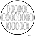
- FIG. 3 shows a cross section of an embodiment with a housing device with horizontal chambers grouped in rows on various levels.
- the height of the chamber can be adapted to the conditions of the distillation to be performed. Among other factors, its height can be a function of the combination of the flow rate that can pass through the microgroove or micro undulations, the evaporation ratio and the desired concentration of the unevaporated brine.
- FIG. 4 shows a cross section and a view of the outer face of an embodiment with a chamber covered with microgrooves with an irregular corrugated section 10.
- This section 10 allows the chamber to occupy a volume similar to that occupied by a bundle of tubes in a current configuration of a state-of-the-art shell and tubes latent heat exchanger.
Landscapes
- Chemical & Material Sciences (AREA)
- Engineering & Computer Science (AREA)
- Chemical Kinetics & Catalysis (AREA)
- Life Sciences & Earth Sciences (AREA)
- Physics & Mathematics (AREA)
- Thermal Sciences (AREA)
- Mechanical Engineering (AREA)
- General Engineering & Computer Science (AREA)
- Sustainable Development (AREA)
- Environmental & Geological Engineering (AREA)
- Hydrology & Water Resources (AREA)
- Water Supply & Treatment (AREA)
- Organic Chemistry (AREA)
- Crystallography & Structural Chemistry (AREA)
- Vaporization, Distillation, Condensation, Sublimation, And Cold Traps (AREA)
- Heat Treatment Of Water, Waste Water Or Sewage (AREA)
- Heat-Exchange Devices With Radiators And Conduit Assemblies (AREA)
- Drying Of Solid Materials (AREA)
- Drying Of Gases (AREA)
- Physical Or Chemical Processes And Apparatus (AREA)
Applications Claiming Priority (2)
| Application Number | Priority Date | Filing Date | Title |
|---|---|---|---|
| ES201731494U ES1203439Y (es) | 2017-12-05 | 2017-12-05 | Cámara intercambiadora de calor latente |
| PCT/ES2018/070781 WO2019110861A1 (es) | 2017-12-05 | 2018-12-04 | Disposicion de camara intercambiadora de calor latente |
Publications (4)
| Publication Number | Publication Date |
|---|---|
| EP3722728A1 true EP3722728A1 (de) | 2020-10-14 |
| EP3722728A4 EP3722728A4 (de) | 2021-10-13 |
| EP3722728B1 EP3722728B1 (de) | 2025-06-18 |
| EP3722728C0 EP3722728C0 (de) | 2025-06-18 |
Family
ID=60971511
Family Applications (3)
| Application Number | Title | Priority Date | Filing Date |
|---|---|---|---|
| EP18887165.1A Active EP3722728B1 (de) | 2017-12-05 | 2018-12-04 | Latentwärmetauscherkammer mit einer anordnung. |
| EP18885762.7A Active EP3722726B1 (de) | 2017-12-05 | 2018-12-04 | Mechanische dampfkompressionssystemsanordnung mit niedrigem verdichtungsverhältnis |
| EP18885834.4A Active EP3722727B1 (de) | 2017-12-05 | 2018-12-05 | Multieffektdestillation mit thermodampfkompression (tvc-med) mit niedrigem verdichtungsverhältnis |
Family Applications After (2)
| Application Number | Title | Priority Date | Filing Date |
|---|---|---|---|
| EP18885762.7A Active EP3722726B1 (de) | 2017-12-05 | 2018-12-04 | Mechanische dampfkompressionssystemsanordnung mit niedrigem verdichtungsverhältnis |
| EP18885834.4A Active EP3722727B1 (de) | 2017-12-05 | 2018-12-05 | Multieffektdestillation mit thermodampfkompression (tvc-med) mit niedrigem verdichtungsverhältnis |
Country Status (15)
| Country | Link |
|---|---|
| US (2) | US11209217B2 (de) |
| EP (3) | EP3722728B1 (de) |
| JP (2) | JP7333522B2 (de) |
| CN (2) | CN111670333B (de) |
| AU (2) | AU2018379534A1 (de) |
| BR (1) | BR112020011327A2 (de) |
| CA (2) | CA3084297A1 (de) |
| ES (6) | ES1203439Y (de) |
| IL (2) | IL275090B2 (de) |
| JO (2) | JOP20200139A1 (de) |
| MX (2) | MX2020005902A (de) |
| SA (3) | SA520412133B1 (de) |
| SG (2) | SG11202005266UA (de) |
| WO (3) | WO2019110861A1 (de) |
| ZA (2) | ZA202003412B (de) |
Families Citing this family (5)
| Publication number | Priority date | Publication date | Assignee | Title |
|---|---|---|---|---|
| CN108671570A (zh) * | 2018-05-08 | 2018-10-19 | 大连理工大学 | 一种倾斜椭圆管降膜蒸发器 |
| ES1250825Y (es) * | 2020-04-08 | 2020-10-28 | Wga Water Global Access Sl | Dispositivo desalinizador de compresion por inyeccion hidraulica |
| WO2024052583A1 (es) * | 2022-09-08 | 2024-03-14 | Wga Water Global Access S.L. | Dispositivo desalinizador multiefecto multitren memtd |
| CN115581937B (zh) * | 2022-11-11 | 2025-09-05 | 中石化节能技术服务有限公司 | 一种评价精馏过程碳足迹中共生产品的分配方法 |
| CN118811919B (zh) * | 2024-09-12 | 2024-12-20 | 中穗华生态科技(上海)有限公司 | 一种基于真空管光热蒸发的洁净水获取装置 |
Family Cites Families (36)
| Publication number | Priority date | Publication date | Assignee | Title |
|---|---|---|---|---|
| US3305454A (en) | 1965-02-19 | 1967-02-21 | Desal Ltd | Series evaporator-tray compressor type vacuum still |
| JPS5647469B2 (de) * | 1975-02-13 | 1981-11-10 | ||
| AU3295378A (en) * | 1978-02-02 | 1978-07-06 | Q Dot Corp | Shaping tool for producing a wick |
| JPH0794238B2 (ja) * | 1991-10-25 | 1995-10-11 | 宇宙開発事業団 | 噴霧冷却式除熱器 |
| CN1065521A (zh) * | 1991-12-31 | 1992-10-21 | 吕智民 | 开式热管 |
| JPH10314829A (ja) * | 1997-05-15 | 1998-12-02 | Hitachi Cable Ltd | 高温ヒートパイプ用伝熱管及び該管の製造方法 |
| US6951243B2 (en) * | 2003-10-09 | 2005-10-04 | Sandia National Laboratories | Axially tapered and bilayer microchannels for evaporative coolling devices |
| BRPI0507567A (pt) * | 2004-02-10 | 2007-07-03 | Texas A & M Univ Sys | sistema e método de eveporação por compressão de vapor |
| FR2867771B1 (fr) * | 2004-03-18 | 2006-07-21 | Int De Dessalement Soc | Procede et installation de dessalement d'eau de mer par distillation a effets multiples et thermocompression de vapeur fonctionnant avec differentes pressions de vapeur motrice |
| JP2006181516A (ja) | 2004-12-28 | 2006-07-13 | Sanyo Electric Co Ltd | 太陽光発電利用の真水生成装置 |
| US7222659B2 (en) * | 2005-04-12 | 2007-05-29 | Alexander Levin | Heat and cold storage multistage tower with application of PCM |
| US20070246193A1 (en) * | 2006-04-20 | 2007-10-25 | Bhatti Mohinder S | Orientation insensitive thermosiphon of v-configuration |
| MX2009003855A (es) * | 2006-10-10 | 2009-10-13 | Texas A & M Univ Sys | Sistema de desalinizacion. |
| GB2443802A (en) * | 2006-11-08 | 2008-05-21 | L E T Leading Edge Technologie | Thermal desalination plant integrated upgrading process and apparatus |
| CN101126613B (zh) * | 2007-09-12 | 2010-06-02 | 苏州新太铜高效管有限公司 | 冷凝器用换热管 |
| WO2010026953A1 (ja) | 2008-09-04 | 2010-03-11 | Takeda Seiichi | エネルギー効率の高い蒸留水及び/又は濃縮水の製造方法と装置 |
| US20100252410A1 (en) * | 2009-03-30 | 2010-10-07 | Frederick William Millar | Water Purification Device and Method |
| JP3153941U (ja) * | 2009-07-14 | 2009-09-24 | 奇宏電子深▲しん▼有限公司 | 放熱器の改良構造 |
| US8292272B2 (en) * | 2009-09-04 | 2012-10-23 | Massachusetts Institute Of Technology | Water separation under reduced pressure |
| CN102235615A (zh) * | 2010-04-21 | 2011-11-09 | 中国科学院工程热物理研究所 | 一种腔式发光二极管灯 |
| JP2013088049A (ja) | 2011-10-19 | 2013-05-13 | Mitsubishi Plastics Inc | 潜熱蓄熱槽、及び給湯システム |
| CN202692733U (zh) * | 2012-05-09 | 2013-01-23 | 苏州新太铜高效管有限公司 | 带有吸液芯体的翅片冷凝管 |
| CN202936219U (zh) * | 2012-12-12 | 2013-05-15 | 众和海水淡化工程有限公司 | 一种小型tvc-med海水淡化装置 |
| CN103047891B (zh) * | 2012-12-20 | 2014-11-05 | 苏州新太铜高效管有限公司 | 网状外表面的降膜蒸发管 |
| WO2015014387A1 (fr) * | 2013-07-29 | 2015-02-05 | Francois-Mathieu Winandy | Procedes et installations de dessalement d'eau par distillation a compression mecanique de vapeur |
| NO340556B1 (no) * | 2014-05-30 | 2017-05-08 | Pleat As | Anordning for varmeveksling |
| MX2017013299A (es) | 2015-04-23 | 2018-01-25 | Wga Water Global Access S L | Tubo condensador-evaporador. |
| US20170030656A1 (en) * | 2015-07-31 | 2017-02-02 | Sfi Electronics Technology Inc. | Thermal energy storage facility having functions of heat storage and heat release |
| US10390500B2 (en) * | 2015-10-09 | 2019-08-27 | KC Harvey Environmental, LLC | Desalination membranes for subsurface irrigation |
| CN105202955B (zh) * | 2015-11-16 | 2018-06-26 | 盐城市轩源加热设备科技有限公司 | 一种外部设置翅片的热管 |
| CN110402364B (zh) * | 2016-12-13 | 2022-06-10 | 得克萨斯A&M大学体系 | 特别应用于蒸汽压缩脱盐的显热交换器和潜热交换器 |
| CN206481096U (zh) * | 2016-12-21 | 2017-09-08 | 中国科学院工程热物理研究所 | 利用可再生能源进行微细尺度换热的野外便携式电源 |
| CN107167013B (zh) * | 2017-06-28 | 2018-09-25 | 天津朗华科技发展有限公司 | 一种蓄能换热装置 |
| GR20170100407A (el) * | 2017-09-07 | 2019-05-09 | Αριστειδης Εμμανουηλ Δερμιτζακης | Συμπιεστης πολλαπλων θαλαμων μηχανικης επανασυμπιεσης ατμων |
| US10399003B2 (en) * | 2018-02-05 | 2019-09-03 | King Fahd University Of Petroleum And Minerals | Mechanical vapor compression desalination system |
| US10935325B2 (en) * | 2018-09-28 | 2021-03-02 | Microsoft Technology Licensing, Llc | Two-phase thermodynamic system having a porous microstructure sheet with varying surface energy to optimize utilization of a working fluid |
-
2017
- 2017-12-05 ES ES201731494U patent/ES1203439Y/es not_active Expired - Fee Related
- 2017-12-13 ES ES201731521U patent/ES1207636Y/es not_active Expired - Fee Related
- 2017-12-19 ES ES201731548U patent/ES1209591Y/es not_active Expired - Fee Related
-
2018
- 2018-12-04 SG SG11202005266UA patent/SG11202005266UA/en unknown
- 2018-12-04 CA CA3084297A patent/CA3084297A1/en active Pending
- 2018-12-04 IL IL275090A patent/IL275090B2/en unknown
- 2018-12-04 CN CN201880078712.1A patent/CN111670333B/zh active Active
- 2018-12-04 WO PCT/ES2018/070781 patent/WO2019110861A1/es not_active Ceased
- 2018-12-04 EP EP18887165.1A patent/EP3722728B1/de active Active
- 2018-12-04 EP EP18885762.7A patent/EP3722726B1/de active Active
- 2018-12-04 US US16/770,511 patent/US11209217B2/en active Active
- 2018-12-04 ES ES18887165T patent/ES3036917T3/es active Active
- 2018-12-04 AU AU2018379534A patent/AU2018379534A1/en not_active Abandoned
- 2018-12-04 MX MX2020005902A patent/MX2020005902A/es unknown
- 2018-12-04 JP JP2020530972A patent/JP7333522B2/ja active Active
- 2018-12-04 US US16/770,502 patent/US11662156B2/en active Active
- 2018-12-04 JP JP2020530956A patent/JP2021505836A/ja active Pending
- 2018-12-04 AU AU2018381061A patent/AU2018381061B2/en active Active
- 2018-12-04 ES ES18885762T patent/ES3036046T3/es active Active
- 2018-12-04 CN CN201880078474.4A patent/CN111656123B/zh not_active Expired - Fee Related
- 2018-12-04 IL IL275088A patent/IL275088B2/en unknown
- 2018-12-04 MX MX2020005901A patent/MX2020005901A/es unknown
- 2018-12-04 BR BR112020011327-1A patent/BR112020011327A2/pt not_active IP Right Cessation
- 2018-12-04 CA CA3084292A patent/CA3084292A1/en active Pending
- 2018-12-04 WO PCT/ES2018/070782 patent/WO2019110862A1/es not_active Ceased
- 2018-12-04 SG SG11202005097SA patent/SG11202005097SA/en unknown
- 2018-12-05 EP EP18885834.4A patent/EP3722727B1/de active Active
- 2018-12-05 WO PCT/ES2018/070786 patent/WO2019110863A1/es not_active Ceased
- 2018-12-05 ES ES18885834T patent/ES3034957T3/es active Active
-
2020
- 2020-06-04 SA SA520412133A patent/SA520412133B1/ar unknown
- 2020-06-04 SA SA520412130A patent/SA520412130B1/ar unknown
- 2020-06-04 JO JOP/2020/0139A patent/JOP20200139A1/ar unknown
- 2020-06-04 SA SA520412132A patent/SA520412132B1/ar unknown
- 2020-06-04 JO JOP/2020/0138A patent/JOP20200138A1/ar unknown
- 2020-06-08 ZA ZA2020/03412A patent/ZA202003412B/en unknown
- 2020-06-08 ZA ZA2020/03411A patent/ZA202003411B/en unknown
Also Published As
Similar Documents
| Publication | Publication Date | Title |
|---|---|---|
| EP3722728B1 (de) | Latentwärmetauscherkammer mit einer anordnung. | |
| US7269966B2 (en) | Heat and mass exchanger | |
| JP3269634B2 (ja) | 液体分配装置及び流下液膜式熱交換器並びに吸収式冷凍機 | |
| US4019571A (en) | Gravity assisted wick system for condensers, evaporators and heat pipes | |
| RU2666919C1 (ru) | Конденсаторно-испарительная труба | |
| JPS58205084A (ja) | 薄膜蒸発式熱交換器 | |
| RU2772386C2 (ru) | Устройство для камеры теплообменника скрытой теплоты | |
| CN106288497A (zh) | 吸收式制冷单元内部换热组件、吸收式制冷单元及矩阵 | |
| JP3572869B2 (ja) | 吸収式冷凍機の散布装置 | |
| BR112020011313B1 (pt) | Arranjo para uma câmara de trocador de calor latente | |
| CN206207784U (zh) | 吸收式制冷单元内部换热组件、吸收式制冷单元及矩阵 | |
| WO2017088772A1 (zh) | 吸收式制冷单元无循环泵冷媒蒸发器、制冷单元及矩阵 | |
| JP2009068723A (ja) | 吸収冷凍機 | |
| CN114543395B (zh) | 用于制冷系统的降膜蒸发器及制冷系统 | |
| JP2008232571A (ja) | 吸収冷凍機 | |
| JPS61225582A (ja) | ヒ−トパイプの内部構造 | |
| JPH0674956B2 (ja) | ヒートパイプ | |
| JPS60181587A (ja) | カスケ−ドサイクル式熱変換システム | |
| JPH0257836A (ja) | ヒートパイプ式蓄熱水槽装置 | |
| JPH07190558A (ja) | 吸収式冷凍装置 | |
| JPH0522838B2 (de) | ||
| JPS58150795A (ja) | ヒ−トパイプ | |
| JP2015132454A (ja) | 蒸発式冷却熱交換器 | |
| JP2015114041A (ja) | 蒸発式冷却熱交換器 | |
| JPH0635875U (ja) | 吸収式氷製造蓄冷熱装置 |
Legal Events
| Date | Code | Title | Description |
|---|---|---|---|
| STAA | Information on the status of an ep patent application or granted ep patent |
Free format text: STATUS: THE INTERNATIONAL PUBLICATION HAS BEEN MADE |
|
| PUAI | Public reference made under article 153(3) epc to a published international application that has entered the european phase |
Free format text: ORIGINAL CODE: 0009012 |
|
| STAA | Information on the status of an ep patent application or granted ep patent |
Free format text: STATUS: REQUEST FOR EXAMINATION WAS MADE |
|
| 17P | Request for examination filed |
Effective date: 20200605 |
|
| AK | Designated contracting states |
Kind code of ref document: A1 Designated state(s): AL AT BE BG CH CY CZ DE DK EE ES FI FR GB GR HR HU IE IS IT LI LT LU LV MC MK MT NL NO PL PT RO RS SE SI SK SM TR |
|
| AX | Request for extension of the european patent |
Extension state: BA ME |
|
| DAV | Request for validation of the european patent (deleted) | ||
| DAX | Request for extension of the european patent (deleted) | ||
| A4 | Supplementary search report drawn up and despatched |
Effective date: 20210914 |
|
| RIC1 | Information provided on ipc code assigned before grant |
Ipc: F28F 13/00 20060101ALI20210908BHEP Ipc: F28D 20/02 20060101AFI20210908BHEP |
|
| STAA | Information on the status of an ep patent application or granted ep patent |
Free format text: STATUS: EXAMINATION IS IN PROGRESS |
|
| 17Q | First examination report despatched |
Effective date: 20230830 |
|
| GRAP | Despatch of communication of intention to grant a patent |
Free format text: ORIGINAL CODE: EPIDOSNIGR1 |
|
| STAA | Information on the status of an ep patent application or granted ep patent |
Free format text: STATUS: GRANT OF PATENT IS INTENDED |
|
| INTG | Intention to grant announced |
Effective date: 20250113 |
|
| GRAS | Grant fee paid |
Free format text: ORIGINAL CODE: EPIDOSNIGR3 |
|
| GRAA | (expected) grant |
Free format text: ORIGINAL CODE: 0009210 |
|
| STAA | Information on the status of an ep patent application or granted ep patent |
Free format text: STATUS: THE PATENT HAS BEEN GRANTED |
|
| AK | Designated contracting states |
Kind code of ref document: B1 Designated state(s): AL AT BE BG CH CY CZ DE DK EE ES FI FR GB GR HR HU IE IS IT LI LT LU LV MC MK MT NL NO PL PT RO RS SE SI SK SM TR |
|
| REG | Reference to a national code |
Ref country code: GB Ref legal event code: FG4D |
|
| REG | Reference to a national code |
Ref country code: CH Ref legal event code: EP |
|
| REG | Reference to a national code |
Ref country code: DE Ref legal event code: R096 Ref document number: 602018082785 Country of ref document: DE |
|
| REG | Reference to a national code |
Ref country code: CH Ref legal event code: EP |
|
| REG | Reference to a national code |
Ref country code: IE Ref legal event code: FG4D |
|
| U01 | Request for unitary effect filed |
Effective date: 20250718 |
|
| U07 | Unitary effect registered |
Designated state(s): AT BE BG DE DK EE FI FR IT LT LU LV MT NL PT RO SE SI Effective date: 20250724 |
|
| REG | Reference to a national code |
Ref country code: ES Ref legal event code: FG2A Ref document number: 3036917 Country of ref document: ES Kind code of ref document: T3 Effective date: 20250925 |
|
| PG25 | Lapsed in a contracting state [announced via postgrant information from national office to epo] |
Ref country code: GR Free format text: LAPSE BECAUSE OF FAILURE TO SUBMIT A TRANSLATION OF THE DESCRIPTION OR TO PAY THE FEE WITHIN THE PRESCRIBED TIME-LIMIT Effective date: 20250919 |
|
| PG25 | Lapsed in a contracting state [announced via postgrant information from national office to epo] |
Ref country code: HR Free format text: LAPSE BECAUSE OF FAILURE TO SUBMIT A TRANSLATION OF THE DESCRIPTION OR TO PAY THE FEE WITHIN THE PRESCRIBED TIME-LIMIT Effective date: 20250618 |
|
| PG25 | Lapsed in a contracting state [announced via postgrant information from national office to epo] |
Ref country code: RS Free format text: LAPSE BECAUSE OF FAILURE TO SUBMIT A TRANSLATION OF THE DESCRIPTION OR TO PAY THE FEE WITHIN THE PRESCRIBED TIME-LIMIT Effective date: 20250918 |
|
| REG | Reference to a national code |
Ref country code: CH Ref legal event code: U11 Free format text: ST27 STATUS EVENT CODE: U-0-0-U10-U11 (AS PROVIDED BY THE NATIONAL OFFICE) Effective date: 20260101 |
|
| PG25 | Lapsed in a contracting state [announced via postgrant information from national office to epo] |
Ref country code: IS Free format text: LAPSE BECAUSE OF FAILURE TO SUBMIT A TRANSLATION OF THE DESCRIPTION OR TO PAY THE FEE WITHIN THE PRESCRIBED TIME-LIMIT Effective date: 20251018 |
|
| PGFP | Annual fee paid to national office [announced via postgrant information from national office to epo] |
Ref country code: NO Payment date: 20251222 Year of fee payment: 8 |
|
| PG25 | Lapsed in a contracting state [announced via postgrant information from national office to epo] |
Ref country code: SM Free format text: LAPSE BECAUSE OF FAILURE TO SUBMIT A TRANSLATION OF THE DESCRIPTION OR TO PAY THE FEE WITHIN THE PRESCRIBED TIME-LIMIT Effective date: 20250618 |
|
| PG25 | Lapsed in a contracting state [announced via postgrant information from national office to epo] |
Ref country code: CZ Free format text: LAPSE BECAUSE OF FAILURE TO SUBMIT A TRANSLATION OF THE DESCRIPTION OR TO PAY THE FEE WITHIN THE PRESCRIBED TIME-LIMIT Effective date: 20250618 |
|
| PG25 | Lapsed in a contracting state [announced via postgrant information from national office to epo] |
Ref country code: PL Free format text: LAPSE BECAUSE OF FAILURE TO SUBMIT A TRANSLATION OF THE DESCRIPTION OR TO PAY THE FEE WITHIN THE PRESCRIBED TIME-LIMIT Effective date: 20250618 |
|
| PG25 | Lapsed in a contracting state [announced via postgrant information from national office to epo] |
Ref country code: SK Free format text: LAPSE BECAUSE OF FAILURE TO SUBMIT A TRANSLATION OF THE DESCRIPTION OR TO PAY THE FEE WITHIN THE PRESCRIBED TIME-LIMIT Effective date: 20250618 |
|
| U20 | Renewal fee for the european patent with unitary effect paid |
Year of fee payment: 8 Effective date: 20251231 |
|
| PGFP | Annual fee paid to national office [announced via postgrant information from national office to epo] |
Ref country code: ES Payment date: 20260105 Year of fee payment: 8 |
|
| PGFP | Annual fee paid to national office [announced via postgrant information from national office to epo] |
Ref country code: CH Payment date: 20260101 Year of fee payment: 8 |
|
| PLBE | No opposition filed within time limit |
Free format text: ORIGINAL CODE: 0009261 |
|
| STAA | Information on the status of an ep patent application or granted ep patent |
Free format text: STATUS: NO OPPOSITION FILED WITHIN TIME LIMIT |
|
| REG | Reference to a national code |
Ref country code: CH Ref legal event code: L10 Free format text: ST27 STATUS EVENT CODE: U-0-0-L10-L00 (AS PROVIDED BY THE NATIONAL OFFICE) Effective date: 20260430 |