EP3722733A1 - Dispositif d'allumage à distance de munitions - Google Patents
Dispositif d'allumage à distance de munitions Download PDFInfo
- Publication number
- EP3722733A1 EP3722733A1 EP20160562.3A EP20160562A EP3722733A1 EP 3722733 A1 EP3722733 A1 EP 3722733A1 EP 20160562 A EP20160562 A EP 20160562A EP 3722733 A1 EP3722733 A1 EP 3722733A1
- Authority
- EP
- European Patent Office
- Prior art keywords
- lever
- guide element
- movement
- hammer
- ignition
- Prior art date
- Legal status (The legal status is an assumption and is not a legal conclusion. Google has not performed a legal analysis and makes no representation as to the accuracy of the status listed.)
- Granted
Links
Images



Classifications
-
- F—MECHANICAL ENGINEERING; LIGHTING; HEATING; WEAPONS; BLASTING
- F41—WEAPONS
- F41A—FUNCTIONAL FEATURES OR DETAILS COMMON TO BOTH SMALLARMS AND ORDNANCE, e.g. CANNONS; MOUNTINGS FOR SMALLARMS OR ORDNANCE
- F41A19/00—Firing or trigger mechanisms; Cocking mechanisms
- F41A19/06—Mechanical firing mechanisms, e.g. counterrecoil firing, recoil actuated firing mechanisms
- F41A19/08—Mechanical firing mechanisms, e.g. counterrecoil firing, recoil actuated firing mechanisms remote actuated; lanyard actuated
-
- F—MECHANICAL ENGINEERING; LIGHTING; HEATING; WEAPONS; BLASTING
- F41—WEAPONS
- F41A—FUNCTIONAL FEATURES OR DETAILS COMMON TO BOTH SMALLARMS AND ORDNANCE, e.g. CANNONS; MOUNTINGS FOR SMALLARMS OR ORDNANCE
- F41A19/00—Firing or trigger mechanisms; Cocking mechanisms
- F41A19/06—Mechanical firing mechanisms, e.g. counterrecoil firing, recoil actuated firing mechanisms
- F41A19/13—Percussion or firing pins, i.e. fixed or slidably-mounted striker elements; Mountings therefor
-
- F—MECHANICAL ENGINEERING; LIGHTING; HEATING; WEAPONS; BLASTING
- F41—WEAPONS
- F41A—FUNCTIONAL FEATURES OR DETAILS COMMON TO BOTH SMALLARMS AND ORDNANCE, e.g. CANNONS; MOUNTINGS FOR SMALLARMS OR ORDNANCE
- F41A19/00—Firing or trigger mechanisms; Cocking mechanisms
- F41A19/06—Mechanical firing mechanisms, e.g. counterrecoil firing, recoil actuated firing mechanisms
- F41A19/25—Mechanical firing mechanisms, e.g. counterrecoil firing, recoil actuated firing mechanisms having only slidably-mounted striker elements, i.e. percussion or firing pins
Definitions
- the present invention relates to a device for the remote-controlled ignition of ammunition.
- mechanical ignition by means of an ignition device is taken into account here.
- a primer is typically used as an ignition device.
- a mechanical hammer is then used to activate the ignition device and to ignite the ammunition.
- Corresponding devices are required in different types of weapons for different ammunition. This ranges from hand-held weapons to permanently mounted weapon stations.
- Corresponding remote control devices for igniting cartridged ammunition with an ignition element work predominantly with mechanically preloaded strikers. This includes a remote-controlled trigger mechanism and a remote-controlled safety system, which are intended to prevent unintentional firing. By pretensioning strikers, however, it cannot be ruled out that a shot can be fired as a result of incorrect operation, since the energy required for the ignition pulse is available and can be called up by the pretension.
- Corresponding devices are, for example, from CH 711 375 A2 known. Disclosed is a separate solution for pretensioning the hammer, for triggering the hammer and for securing the hammer. The hammer is operated with the aid of an actuator.
- the weapon can be in a non-reliably defined state and it can happen that the ammunition is unintentionally ignited.
- the present invention addresses this problem and proposes a solution.
- the object of the present invention is therefore to provide a device for the remote-controlled ignition of ammunition which functions reliably and offers improved security against unintentional ignition of the ammunition compared to the prior art. This object is achieved with the features of the present main claim.
- a device for the remote-controlled ignition of ammunition with an ignition device and a hammer.
- the ignition device is preferably designed as a primer cap.
- the aforementioned hammer is designed as a mechanical hammer which can act on the ignition device and cause the ignition device to ignite the ammunition.
- the device according to the invention includes a movable lever which can move the hammer.
- the hammer can be arranged directly on the lever.
- the hammer can also be arranged indirectly on the lever, for example by means of a joint.
- a guide element is movably mounted in the device and can assume several positions due to its mobility, but at least one rest position and one activation position.
- the lever is designed such that the guide element can set the lever in motion, preferably in a rotary motion, when it is moved.
- the guide element can thus come into operative connection with the lever in order to carry out the aforementioned movement. This preferably takes place when the guide element is moved from the rest position into the activation position.
- a fuse is provided according to the invention, which can hinder the movement of the lever. Since the lever is connected to the hammer in such a way that the lever can move the hammer, the movement of the hammer is also prevented by the safety device. This creates considerable security against unintentional ignition of the ammunition.
- a housing is provided for the device.
- This housing can be designed to be lockable in order to be able to offer protection for the device.
- the device can be introduced into the housing and also serviced there.
- the guide element assumes its rest position as a starting position.
- the guide element By triggering the movement of the guide element by remote control, it can now be moved out of its rest position, specifically in the direction of its activation position.
- This is preferably implemented by a remotely controllable actuator which can exert a driving force on the guide element. This driving force then sets the guide element in motion and moves it out of its rest position.
- an electromagnet is proposed which can be magnetized or demagnetized remotely.
- the guide element moves the lever and ensures that the hammer is moved in the direction of the ignition device at a speed that the hammer activates the ignition device so that the ignition device can ignite the ammunition.
- the guide element After the movement of the guide element and the subsequent ignition of the ammunition, the guide element is moved back into its rest position and the device is again in the starting or rest position.
- the device In order to return the guide element to its rest position, it is preferably proposed that the device contain a return element which can move the guide element in its rest position when there is no drive force.
- a return element which can move the guide element in its rest position when there is no drive force.
- a spring can be provided for this purpose, but hydraulic, electrical or pneumatic return elements are also conceivable.
- the actuator When using a return element, the actuator must be designed so that the driving force can overcome the force of the return element in order to transfer the guide element from its rest position to the activation position.
- the invention proposes to use a fuse which can hinder the movement of the lever or the hammer.
- the safety device can be designed as a safety pin, but mechanical brakes or mechanical locking of the lever are also conceivable.
- a safety drive which, on the one hand, can activate or deactivate the safety device.
- the safety drive can also be designed to be remote-controlled.
- the lever can be supported by a bearing.
- a rotary movement of the lever can be realized by such a bearing.
- the fuse can also be built into the bearing for this purpose in order to prevent rotation in the bearing.
- the striking piece can be designed in such a way that its movement can be restricted, but can also be released in order to act on the ignition device.
- a tensioning element as an energy store, which uses stored energy to move the hammer in the direction of the ignition device. This results in an increased impact force on the ignition device. A safe ignition is created.
- the guide element can be designed in such a way that it contains a cam. It is proposed to mount the cam so that it can rotate about a pivot point. The cam can then interact with the lever via the guide element.
- the lever can in turn be designed in such a way that it has a slope which, in relation to the level of the lever, increases in relation to the direction of movement of the guide element.
- the cam when the guide element is moved out of the rest position, the cam is guided over this slope, as a result of which the lever is set in motion and the hammer is set in motion. Energy is supplied to the clamping element by the movement of the hammer. If the cam continues to move beyond the incline of the lever, the cam then releases the movement of the lever and then also the movement of the hammer. The previously stored energy from the clamping element is transferred to the now free hammer, whereby the hammer is moved in the direction of the ignition device and can act on it.
- the cam When the guide element of this embodiment is returned, the cam now strikes the slope of the lever and is thereby set in rotary motion during the further return movement of the guide element in order to get over the slope.
- the guide element together with the cam can be returned to the rest position.
- the cam preferably has a turnstile for its function. This enables the cam to rotate when the guide element is returned to the rest position. When the guide element moves out of the rest position, the turnstile blocks the rotary movement so that the cam does not rotate during this movement.
- the lever comprises a stop in order to limit the movement of the lever.
- a hold-down device is provided on the guide element as a backup.
- the lever again has the aforementioned incline, which in the rest position of the guide element has a surface which runs parallel to the direction of movement of the guide element and with which the hold-down interacts. The lever is in the stop at this moment.
- the guide element contain a movable pressure piece.
- a pressure or a force is applied to the pressure piece by means of the tensioning element in the direction of a pressure direction.
- This pressure piece then acts on the lever in the pressure direction and if this has been released via the hold-down device, the pressure piece ensures that the lever together with the hammer is moved in the direction of the ignition device.
- the hold-down device acts as a safety device and the lever cannot move.
- the movement of the guide element then initially ensures the tensioning of the tensioning element. With further movement the hold-down is then no longer in contact with the slope and thus releases the movement of the lever, which is then set in motion by the pressure piece via the clamping element.
- the device contain a toothed rack which can move together with the guide element, for example triggered by the actuator.
- the rack in turn is held in its position by the aforementioned securing device until the movement of the guide element is guided beyond a certain position. The movement of the guide element leads to the unlocking of the fuse.
- the rack is then moved together with the guide element, which in turn can drive a gear via a gear to set the lever in motion. This then in turn triggers the ignition device, as mentioned above, which causes the ammunition to be ignited.
- the Figure 1 shows an embodiment of the device according to the invention.
- a drive force 9 is applied to the guide element 2 by an actuator.
- the guide element 2 contains a cam 3 which is rotatably mounted on the guide element 2 via a pivot point 6. A rotary movement against the direction of rotation 11 can be prevented by means of a turnstile.
- the drive force 9 moves the guide element 2 and the cam 3 arranged on it. It continues to supply mechanical energy to the return element 15 and at the same time removes the fuse 14 when the guide element 2 moves.
- the fuse 14 is also arranged on the guide element 2 and extends in the rest state of the guide element 2 between the hammer 1 and the ignition device 16, so that the Striker 1 cannot come into operative connection with ignition device 16.
- the fuse 14 is moved so that the fuse 14 is no longer located between the hammer 1 and the ignition device.
- the lever 4 has a slope 12 which increases in relation to the plane 19 of the lever 4 to the plane of movement of the guide element 2. Since the cam 3 of the guide element 2 is connected to the lever 4, the cam 3 slides when the guide element 2 moves over the slope 12 of the lever 4. This causes the lever 4 to rotate around the bearing 5 in the direction of rotation indicated offset.
- the lever 4 is connected to the hammer 1 via a joint 7 and displaces it in a linear movement 10 through the rotary movement of the lever 4.
- the hammer 1 is raised and supplies mechanical energy to the clamping element 13.
- the energy stored in the return element 15 is released after the driving force 9 has taken effect and moves the guide element 2 back into the rest position.
- the cam 3 is rotatably mounted via the aforementioned pivot point 6.
- the cam 3 can rotate in a rotary movement 11 over the slope 12 of the lever 4 and go back to the starting position, the device is then again in the starting state and the guide element 2 is in the rest position.
- the fuse 14 With the return movement of the guide element 2, the fuse 14 is simultaneously moved again so that it extends between the hammer 1 and the ignition device.
- the safety device 14 include an inclined surface which, when it is moved under the hammer 1, can lift it. The device is now secured against impacts in the direction of the linear movement of the hammer 1.
- the return element 15 is designed in such a way that the guide element 2 together with the cam 3 cannot overcome the slope 12 of the lever 4 without the support of the driving force 9.
- FIGS. 2 , 3 and 4 show a further embodiment of the device according to the invention, however with a pressure piece 17 and a hold-down device 18 as a safety device 14.
- the energy stored in the clamping device 13 is transferred to the pressure piece and exerts a pressure force directed in the direction of the lever 4, which increases depending on the slope 12 of the lever 4 and the distance covered by the guide element 2 up to the end of the slope 12.
- the pressure piece can execute a linear movement 10 through the compressive force of the clamping element 13.
- the clamping element 13 can again be designed as a spring. But hydraulic, electrical or pneumatic systems are also conceivable here.
- the hammer 1 is arranged directly on the lever 4, the lever 4 being rotatably supported by a bearing 5.
- the hold-down device 18 blocks the rotary movement of the lever 4 via the contact with the slope 12.
- the slope 12 is arranged so that a stop 22 is provided which can limit the rotary movement of the lever 4 in one direction. Via this movement limitation, the slope 12 then has a surface that runs parallel to the direction of movement of the guide element 2 and extends up to the position of the bearing 5 of the lever 4. If for this purpose the hold-down 18 does not move beyond the position of the bearing 5 of the lever 4, the hold-down 18 blocks the movement of the lever 4.
- the hold-down 18 thus functions as a safety device 14.
- the energy stored in the return element 15 is free after the driving force 9 has taken effect and moves the guide element 2 back into its rest position.
- the hold-down device 18 also comes into contact with the slope 12 of the lever 4 and also guides the lever 4 together with the hammer 1 back into the starting position.
- the return element 15 is designed such that in the event of undesired movements in the direction of the drive force 9, the hold-down device 18 can only overcome the resistance of the return element 15 and pass the bearing 5 with the support of the drive force 9. In all other directions, the device is secured by the hold-down device 18, as this is the Holds hammer 1 in position.
- the advantage of this embodiment is that the path that the guide element 2 has to cover can be varied. In this way, it is possible to influence whether the device should have a higher level of safety or a shorter ignition process.
- the prestressing force of the clamping element 13 is also adjustable.
- Figure 5 also shows an embodiment of the device according to the invention.
- the actuator pulls the guide element 2, which releases the securing elements of the securing device 14, which are mounted in a toothed rack 26.
- the securing elements are designed here as pinch rollers.
- the actuator is designed as an electromagnet 21.
- the rack 26 After releasing the pinch rollers, the rack 26 is unlocked and is moved along by the actuator via the guide element 4. The rack 26 transmits the movement to a gear 23 which, via a gear, rotates a bearing 5 on which the lever 4 is located.
- the hammer 1 which can be rotated with the lever 4, is in turn arranged on the lever 4. After a defined angular movement, the hammer 1 strikes the ignition device 16 and thus activates the ignition process.
- the return element 15 moves the guide element 2 together with the rack 26 back into its starting position, whereby the fuse 14 also secures the device again.
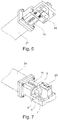
- the Figures 6 and 7 show a further embodiment, this time the actuator moves the guide element 2 out of its rest position, whereby the return element 15 is simultaneously acted upon with energy.
- the actuator is again designed as an electromagnet 21 and the return element 15 as a spring.
- the guide element 2 can act on the pivoted lever 4 and can set it in a rotary movement. This rotary movement and the interaction with the guide element 2 is shown in FIG Figure 8 shown in more detail.
- the guide element 2 After the end of the movement process, the guide element 2 is released and moves back into its rest position by the return element 15. It hits the lever 4 with the hammer 1, whereby the lever 4 is again accelerated and set in rotary motion. At the end of the rotary movement, the hammer 1 strikes the ignition device 16 and can activate the ignition process. The lever 4 rotates around the bearing 5.
- the safety device 14 can limit the movement of the lever 4 so that the latter cannot allow the hammer 1 to strike the ignition element 16. In this embodiment, the safety device 14 can also be used to move the lever 4 back into the starting position for a renewed tightening process.
- the aforementioned safety drive 25 is preferably used for this purpose.
- the fuse 14 is designed as a flap which, for example by means of a projection, moves the lever 4 again in the direction of the guide element 2 when the fuse 14 is introduced.
- All of the aforementioned devices can be accommodated in a housing 24 (not shown).
- the present invention is not limited to the aforementioned features. Rather, further embodiments are conceivable.
- the device could also be designed without a housing. It is also conceivable that the reversing lever does not perform a rotary movement, but a linear movement. Finally, it is also conceivable that the hammer performs an additional rotary movement and not a linear movement.
Landscapes
- Engineering & Computer Science (AREA)
- General Engineering & Computer Science (AREA)
- Portable Nailing Machines And Staplers (AREA)
Priority Applications (1)
| Application Number | Priority Date | Filing Date | Title |
|---|---|---|---|
| EP26157720.9A EP4718014A2 (fr) | 2019-03-22 | 2020-03-03 | Dispositif pour l'allumage à distance de munitions |
Applications Claiming Priority (1)
| Application Number | Priority Date | Filing Date | Title |
|---|---|---|---|
| DE102019107405.3A DE102019107405A1 (de) | 2019-03-22 | 2019-03-22 | Vorrichtung zum fernbedienbaren Anzünden von Munition |
Related Child Applications (2)
| Application Number | Title | Priority Date | Filing Date |
|---|---|---|---|
| EP26157720.9A Division-Into EP4718014A2 (fr) | 2019-03-22 | 2020-03-03 | Dispositif pour l'allumage à distance de munitions |
| EP26157720.9A Division EP4718014A2 (fr) | 2019-03-22 | 2020-03-03 | Dispositif pour l'allumage à distance de munitions |
Publications (2)
| Publication Number | Publication Date |
|---|---|
| EP3722733A1 true EP3722733A1 (fr) | 2020-10-14 |
| EP3722733B1 EP3722733B1 (fr) | 2026-05-06 |
Family
ID=69770413
Family Applications (2)
| Application Number | Title | Priority Date | Filing Date |
|---|---|---|---|
| EP26157720.9A Pending EP4718014A2 (fr) | 2019-03-22 | 2020-03-03 | Dispositif pour l'allumage à distance de munitions |
| EP20160562.3A Active EP3722733B1 (fr) | 2019-03-22 | 2020-03-03 | Dispositif d'allumage à distance de munitions |
Family Applications Before (1)
| Application Number | Title | Priority Date | Filing Date |
|---|---|---|---|
| EP26157720.9A Pending EP4718014A2 (fr) | 2019-03-22 | 2020-03-03 | Dispositif pour l'allumage à distance de munitions |
Country Status (2)
| Country | Link |
|---|---|
| EP (2) | EP4718014A2 (fr) |
| DE (1) | DE102019107405A1 (fr) |
Citations (5)
| Publication number | Priority date | Publication date | Assignee | Title |
|---|---|---|---|---|
| DE3001490A1 (de) * | 1980-01-17 | 1981-07-23 | Industrie-Werke Karlsruhe Augsburg AG Zweigniederlassung Keller & Knappich Augsburg, 8900 Augsburg | Mechanik zum abfeuern an maschinenwaffen |
| EP0611186A1 (fr) * | 1993-02-11 | 1994-08-17 | Societe D'etudes, De Realisations Et D'applications Techniques (S.E.R.A.T.) | Arme d'épaule pour le tir de munitions à forte impulsion |
| EP2048468A2 (fr) * | 2007-10-08 | 2009-04-15 | Rheinmetall Landsysteme GmbH | Commande télécommandée d'armes/de mitrailleuses automatiques |
| EP2282157B1 (fr) | 2009-07-27 | 2014-09-03 | Rheinmetall Landsysteme GmbH | Dispositif d'armement télécommandable pour des mitrailleuses dotées d'un élément coulissant d'armement |
| CH711375A2 (de) | 2015-07-24 | 2017-01-31 | Carl Hoernecke Chem Fabrik Gmbh & Co Kg | Auslöseeinrichtung für ein pyrotechnisches Element, sowie Einrichtung zum Simulieren von Geschosstreffern oder Geschosszündungen oder für die nicht-letale Verteidigung. |
Family Cites Families (6)
| Publication number | Priority date | Publication date | Assignee | Title |
|---|---|---|---|---|
| US1310043A (en) * | 1919-07-15 | Planoqraph co | ||
| GB271925A (en) * | 1926-01-29 | 1927-05-30 | Henry George Andrew Scott | Improvements in and relating to electromagnetic firing gear for guns |
| FR663032A (fr) * | 1928-02-17 | 1929-08-14 | Schneider Et Cie | Mécanisme d'ouverture et de fermeture automatiques des culasses de bouches à feu |
| BE395751A (fr) * | 1932-04-21 | |||
| GB998340A (en) * | 1963-06-19 | 1965-07-14 | Secr Defence | Improvements in or relating to trigger mechanisms |
| ATE523752T1 (de) * | 2006-10-20 | 2011-09-15 | Armatix Gmbh | Umrüstbare sicherheitsvorrichtung für handfeuerwaffe und methode, um eine handfeuerwaffe zu sichern. |
-
2019
- 2019-03-22 DE DE102019107405.3A patent/DE102019107405A1/de active Pending
-
2020
- 2020-03-03 EP EP26157720.9A patent/EP4718014A2/fr active Pending
- 2020-03-03 EP EP20160562.3A patent/EP3722733B1/fr active Active
Patent Citations (5)
| Publication number | Priority date | Publication date | Assignee | Title |
|---|---|---|---|---|
| DE3001490A1 (de) * | 1980-01-17 | 1981-07-23 | Industrie-Werke Karlsruhe Augsburg AG Zweigniederlassung Keller & Knappich Augsburg, 8900 Augsburg | Mechanik zum abfeuern an maschinenwaffen |
| EP0611186A1 (fr) * | 1993-02-11 | 1994-08-17 | Societe D'etudes, De Realisations Et D'applications Techniques (S.E.R.A.T.) | Arme d'épaule pour le tir de munitions à forte impulsion |
| EP2048468A2 (fr) * | 2007-10-08 | 2009-04-15 | Rheinmetall Landsysteme GmbH | Commande télécommandée d'armes/de mitrailleuses automatiques |
| EP2282157B1 (fr) | 2009-07-27 | 2014-09-03 | Rheinmetall Landsysteme GmbH | Dispositif d'armement télécommandable pour des mitrailleuses dotées d'un élément coulissant d'armement |
| CH711375A2 (de) | 2015-07-24 | 2017-01-31 | Carl Hoernecke Chem Fabrik Gmbh & Co Kg | Auslöseeinrichtung für ein pyrotechnisches Element, sowie Einrichtung zum Simulieren von Geschosstreffern oder Geschosszündungen oder für die nicht-letale Verteidigung. |
Also Published As
| Publication number | Publication date |
|---|---|
| DE102019107405A1 (de) | 2020-09-24 |
| EP3722733B1 (fr) | 2026-05-06 |
| EP4718014A2 (fr) | 2026-04-01 |
Similar Documents
| Publication | Publication Date | Title |
|---|---|---|
| DE102005000089A1 (de) | Handgeführtes Eintreibgerät | |
| DE1728159B2 (de) | Sicherungsvorrichtung für einen DrallgeschoBzünder | |
| EP0065101A2 (fr) | Limiteur de rafale pour armes à feu automatiques à percussion par chien | |
| DE1120940B (de) | Aufschlagzuender | |
| EP3155354B1 (fr) | Culasse munie d'un mécanisme de frappe et d'une sécurité de percuteur | |
| WO2011147541A1 (fr) | Réenclencheur de sûreté pour une amorce à levier basculant | |
| DE102011106200B4 (de) | Schlagbolzensicherung | |
| DE19623474A1 (de) | Schußwaffe | |
| EP0505823B1 (fr) | Tendeur dans un système de ceinture de sécurité pour véhicules | |
| EP2109747B1 (fr) | Bloc de culasse pour une arme à canon basculant | |
| EP3722733B1 (fr) | Dispositif d'allumage à distance de munitions | |
| DE1225076B (de) | Abzugeinrichtung fuer mehrteilige Verschluesse von automatischen Feuerwaffen | |
| DE2530707C2 (de) | Unterwasser-Zünder für einen von einem Schleppseil gezogenen Sprenggreifer | |
| EP3722734B1 (fr) | Dispositif d'allumage pour munitions pourvu de dispositif d'allumage mécanique | |
| EP3390949B1 (fr) | Dispositif d'armement pour un percuteur et arme pourvue dudit dispositif d'armement | |
| DE1578479B1 (de) | Geschosszuender | |
| DE102019127918B3 (de) | Vorrichtung zum Antrieb mechanischer Sicherheitssysteme | |
| EP2049863B1 (fr) | Dispositif pour déclencher un percuteur | |
| DE102015214009B4 (de) | Auslöseeinrichtung, sowie Einrichtung zum Simulieren von Geschosstreffern oder Geschosszündungen oder für die nicht-letale Verteidigung | |
| DE2057613B2 (de) | Spann- und Abzugsmechanismus für automatische Schnellfeuerwaffe | |
| DE4021319C2 (fr) | ||
| DE60004740T2 (de) | Abfeuerungsvorrichtung für Geschütz durch den Schlag eines Zünders | |
| EP0139173B1 (fr) | Dispositif de sécurité pour une fusée à percussion d'un projectile | |
| DE10160345A1 (de) | Abzug für eine Feuerwaffe | |
| DE2101181C3 (de) | Aufschlagzünder |
Legal Events
| Date | Code | Title | Description |
|---|---|---|---|
| PUAI | Public reference made under article 153(3) epc to a published international application that has entered the european phase |
Free format text: ORIGINAL CODE: 0009012 |
|
| STAA | Information on the status of an ep patent application or granted ep patent |
Free format text: STATUS: THE APPLICATION HAS BEEN PUBLISHED |
|
| AK | Designated contracting states |
Kind code of ref document: A1 Designated state(s): AL AT BE BG CH CY CZ DE DK EE ES FI FR GB GR HR HU IE IS IT LI LT LU LV MC MK MT NL NO PL PT RO RS SE SI SK SM TR |
|
| AX | Request for extension of the european patent |
Extension state: BA ME |
|
| STAA | Information on the status of an ep patent application or granted ep patent |
Free format text: STATUS: REQUEST FOR EXAMINATION WAS MADE |
|
| 17P | Request for examination filed |
Effective date: 20210210 |
|
| RBV | Designated contracting states (corrected) |
Designated state(s): AL AT BE BG CH CY CZ DE DK EE ES FI FR GB GR HR HU IE IS IT LI LT LU LV MC MK MT NL NO PL PT RO RS SE SI SK SM TR |
|
| RIN1 | Information on inventor provided before grant (corrected) |
Inventor name: LAWITZKE, KLAUS Inventor name: PECHMANN, HINNERK Inventor name: SCHROEDER, JOERN Inventor name: DIE WEITEREN ERFINDER HABEN AUF IHR RECHT VERZICHTET, ALS SOLCHE BEKANNT GEMACHT ZU WERDEN. |
|
| RAP3 | Party data changed (applicant data changed or rights of an application transferred) |
Owner name: RHEINMETALL WAFFE MUNITION GMBH |
|
| STAA | Information on the status of an ep patent application or granted ep patent |
Free format text: STATUS: EXAMINATION IS IN PROGRESS |
|
| 17Q | First examination report despatched |
Effective date: 20230720 |
|
| GRAP | Despatch of communication of intention to grant a patent |
Free format text: ORIGINAL CODE: EPIDOSNIGR1 |
|
| STAA | Information on the status of an ep patent application or granted ep patent |
Free format text: STATUS: GRANT OF PATENT IS INTENDED |
|
| INTG | Intention to grant announced |
Effective date: 20250929 |
|
| GRAS | Grant fee paid |
Free format text: ORIGINAL CODE: EPIDOSNIGR3 |
|
| GRAA | (expected) grant |
Free format text: ORIGINAL CODE: 0009210 |
|
| STAA | Information on the status of an ep patent application or granted ep patent |
Free format text: STATUS: THE PATENT HAS BEEN GRANTED |
|
| AK | Designated contracting states |
Kind code of ref document: B1 Designated state(s): AL AT BE BG CH CY CZ DE DK EE ES FI FR GB GR HR HU IE IS IT LI LT LU LV MC MK MT NL NO PL PT RO RS SE SI SK SM TR |
|
| REG | Reference to a national code |
Ref country code: CH Ref legal event code: F10 Free format text: ST27 STATUS EVENT CODE: U-0-0-F10-F00 (AS PROVIDED BY THE NATIONAL OFFICE) Effective date: 20260506 Ref country code: GB Ref legal event code: FG4D Free format text: NOT ENGLISH |