EP3722739B1 - Appareil et procédé d'inspection d'un profil aérodynamique - Google Patents
Appareil et procédé d'inspection d'un profil aérodynamique Download PDFInfo
- Publication number
- EP3722739B1 EP3722739B1 EP20167289.6A EP20167289A EP3722739B1 EP 3722739 B1 EP3722739 B1 EP 3722739B1 EP 20167289 A EP20167289 A EP 20167289A EP 3722739 B1 EP3722739 B1 EP 3722739B1
- Authority
- EP
- European Patent Office
- Prior art keywords
- pair
- airfoil
- chucks
- profile
- opposing walls
- Prior art date
- Legal status (The legal status is an assumption and is not a legal conclusion. Google has not performed a legal analysis and makes no representation as to the accuracy of the status listed.)
- Active
Links
Images


Classifications
-
- F—MECHANICAL ENGINEERING; LIGHTING; HEATING; WEAPONS; BLASTING
- F01—MACHINES OR ENGINES IN GENERAL; ENGINE PLANTS IN GENERAL; STEAM ENGINES
- F01D—NON-POSITIVE DISPLACEMENT MACHINES OR ENGINES, e.g. STEAM TURBINES
- F01D5/00—Blades; Blade-carrying members; Heating, heat-insulating, cooling or antivibration means on the blades or the members
- F01D5/005—Repairing methods or devices
-
- G—PHYSICS
- G01—MEASURING; TESTING
- G01B—MEASURING LENGTH, THICKNESS OR SIMILAR LINEAR DIMENSIONS; MEASURING ANGLES; MEASURING AREAS; MEASURING IRREGULARITIES OF SURFACES OR CONTOURS
- G01B5/00—Measuring arrangements characterised by the use of mechanical techniques
- G01B5/0002—Arrangements for supporting, fixing or guiding the measuring instrument or the object to be measured
- G01B5/0004—Supports
-
- G—PHYSICS
- G01—MEASURING; TESTING
- G01B—MEASURING LENGTH, THICKNESS OR SIMILAR LINEAR DIMENSIONS; MEASURING ANGLES; MEASURING AREAS; MEASURING IRREGULARITIES OF SURFACES OR CONTOURS
- G01B5/00—Measuring arrangements characterised by the use of mechanical techniques
- G01B5/20—Measuring arrangements characterised by the use of mechanical techniques for measuring contours or curvatures
- G01B5/205—Measuring arrangements characterised by the use of mechanical techniques for measuring contours or curvatures of turbine blades or propellers
Definitions
- the disclosed embodiments relate to an apparatus and method for inspecting an airfoil profile.
- airfoils such as fan blades and vanes in a fan inlet case may require replacement.
- Replacement airfoils should fit in within tight aerodynamic envelops in the engine created by spacing requirements between the airfoil and other structures, such as struts.
- Wenyan Tang et al., 1994 discloses an automatic system for measuring the three-dimensional form of turbine blades wherein measurements are performed by means of rotation of a connecting arm, a measuring rod and the blade itself.
- GB 763793 A discloses a direct-reading gauge apparatus in which similar parts can be successively mounted and accurate readings readily obtained of several predetermined dimensions of each part.
- CN 103753443 B discloses a fixture for turbine blades including a base, a first moving base, a second moving base, a driven end chuck, a bearing sleeve, a driven end couple, an active end chuck and an active end coupling.
- the one of the pair of chucks is connected to the one of the pair of opposing walls by a threaded rod.
- the one of the pair of opposing walls includes a slot to operationally connect with the threaded rod.
- one of the pairs of opposing walls has a threaded nut for operationally receiving the threaded rod.
- the method includes rotating a threaded rod of the one of the pair of chucks within a slot of the apparatus.
- the method includes comparing the measured profile for the airfoil with a measured profile of another airfoil to determine if the measured profile for the another airfoil is within a predetermined tolerance.
- the method includes determining to replace the airfoil with the another airfoil upon comparing the measured profile for the airfoil with a measured profile of another airfoil and determining that the measured profile for the another airfoil is within a predetermined tolerance.
- FIG. 1 schematically illustrates a gas turbine engine 20.
- the gas turbine engine 20 is disclosed herein as a two-spool turbofan that generally incorporates a fan section 22, a compressor section 24, a combustor section 26 and a turbine section 28.
- Alternative engines might include an augmentor section (not shown) among other systems or features.
- the fan section 22 drives air along a bypass flow path B in a bypass duct, while the compressor section 24 drives air along a core flow path C for compression and communication into the combustor section 26 then expansion through the turbine section 28.
- the exemplary engine 20 generally includes a low speed spool 30 and a high speed spool 32 mounted for rotation about an engine central longitudinal axis A relative to an engine static structure 36 via several bearing systems 38. It should be understood that various bearing systems 38 at various locations may alternatively or additionally be provided, and the location of bearing systems 38 may be varied as appropriate to the application.
- the low speed spool 30 generally includes an inner shaft 40 that interconnects a fan 42, a low pressure compressor 44 and a low pressure turbine 46.
- the inner shaft 40 is connected to the fan 42 through a speed change mechanism, which in exemplary gas turbine engine 20 is illustrated as a geared architecture 48 to drive the fan 42 at a lower speed than the low speed spool 30.
- the high speed spool 32 includes an outer shaft 50 that interconnects a high pressure compressor 52 and high pressure turbine 54.
- a combustor 56 is arranged in exemplary gas turbine 20 between the high pressure compressor 52 and the high pressure turbine 54.
- An engine static structure 36 is arranged generally between the high pressure turbine 54 and the low pressure turbine 46.
- the engine static structure 36 further supports bearing systems 38 in the turbine section 28.
- the inner shaft 40 and the outer shaft 50 are concentric and rotate via bearing systems 38 about the engine central longitudinal axis A which is collinear with their longitudinal axes.
- each of the positions of the fan section 22, compressor section 24, combustor section 26, turbine section 28, and fan drive gear system 48 may be varied.
- gear system 48 may be located aft of combustor section 26 or even aft of turbine section 28, and fan section 22 may be positioned forward or aft of the location of gear system 48.
- the engine 20 in one example is a high-bypass geared aircraft engine.
- the engine 20 bypass ratio is greater than about six (6), with an example embodiment being greater than about ten (10)
- the geared architecture 48 is an epicyclic gear train, such as a planetary gear system or other gear system, with a gear reduction ratio of greater than about 2.3 and the low pressure turbine 46 has a pressure ratio that is greater than about five.
- the engine 20 bypass ratio is greater than about ten (10:1)
- the fan diameter is significantly larger than that of the low pressure compressor 44
- the low pressure turbine 46 has a pressure ratio that is greater than about five (5:1).
- Low pressure turbine 46 pressure ratio is pressure measured prior to inlet of low pressure turbine 46 as related to the pressure at the outlet of the low pressure turbine 46 prior to an exhaust nozzle.
- the geared architecture 48 may be an epicycle gear train, such as a planetary gear system or other gear system, with a gear reduction ratio of greater than about 2.3: 1. It should be understood, however, that the above parameters are only exemplary of one embodiment of a geared architecture engine and that the present disclosure is applicable to other gas turbine engines including direct drive turbofans.
- the fan section 22 of the engine 20 is designed for a particular flight condition--typically cruise at about 0.8 Mach and about 35,000 feet (10,668 meters).
- 'TSFC' Thrust Specific Fuel Consumption
- Low fan pressure ratio is the pressure ratio across the fan blade alone, without a Fan Exit Guide Vane (“FEGV”) system.
- the low fan pressure ratio as disclosed herein according to one non-limiting embodiment is less than about 1.45.
- Low corrected fan tip speed is the actual fan tip speed in ft/sec divided by an industry standard temperature correction of [(Tram °R)/(518.7 °R)] 0.5 .
- the "Low corrected fan tip speed” as disclosed herein according to one non-limiting embodiment is less than about 1150 ft/second (350.5 m/sec).
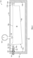
- the apparatus 100 includes a pair of opposing walls 130 connected by a base 140.
- a pair of chucks 150 is provided in the apparatus 100.
- One of the pair of chucks 150a is secured to one of the pair of opposing walls 130a.
- the other one of the chucks 150b is secured to the other one of the pair of opposing walls 130b.
- a profile gauge 160 which may be calibrated, is supported by the pair of opposing walls 130 and configured to move between the pair of chucks 150.
- a rail 170 which may be precision machined, extends between the pair of opposing walls 130 and supports the profile gauge 160 above the pair of chucks 150.
- the profile gauge 160 includes a probe 180 configured for engaging a leading edge 90a of an airfoil 90 secured in the apparatus 100.
- one of the pair of chucks 150a is configured to move toward the other one of the pair of chucks 150b.
- the other one of the pair of chucks 150b is fixed against the other one of the pair of opposing walls 130b.
- the one of the pair of chucks 150a is connected to the one of the pair of opposing walls 130a by a threaded rod 190.
- the one of the pair of opposing walls 130a includes a slot 200, which may be threaded, to operationally connect with the threaded rod 190.
- the slot 200 may be a threaded nut.
- the one of the pair of opposing walls 130a may include a hole 195 aligned with the slot 200 so that the threaded rod 190 may pass through the one of the pair of opposing walls 130 when retracting and advancing the threaded rod 190.
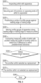
- a method or process S200 of inspecting the airfoil 90 which may be a vane, with the apparatus 100.
- the process includes step S210 of securing a pair of trunnions 210 on opposing ends 215 of the airfoil 90 to the apparatus 100 such that the leading edge 90a of the airfoil 90 is positioned to be inspected by the apparatus 100.
- the pair of trunnions 210 form the axis of rotation, also referred to as the radial axis, of the airfoil 90.
- One of the pair of trunnions 210a is an inner diameter (ID) trunnion and the other one of the pair of trunnions 210b is an outer diameter (OD) trunnion.
- ID inner diameter
- OD outer diameter
- the pair of trunnions 210 are secured between the pair of chucks 150 of the apparatus 100 by advancing one of the pair of chucks 150a toward the other one of the pair of chucks 150b while the other one of the pair of chucks 150b remains stationary.
- the threaded rod 190 of the one of the pair of chucks 150a is rotated within the slot 200 of the apparatus 100. From this, one of the pair of chucks 150a engages one of the pair of trunnions 210a and the other one of the pair of chucks 150b engages the other one of the trunnions 210b.
- Step S220 includes positioning a probe 180 of the profile gauge 160 against the leading edge 90a of the airfoil 90 secured in the apparatus 100.
- Step S230 includes moving the profile gauge 160 of the apparatus 100 along the leading edge 90a of the airfoil 90 in order to obtain a measured profile of the leading edge 90a.
- Step S240 includes comparing the measured profile of the airfoil 90 with another measured profile of a leading edge 250a of another airfoil 260 ( FIG. 4 ), which may be another vane, to determine if the another measured profile is within a predetermined tolerance.
- the airfoil 90 is a vane for the fan inlet case 92
- the another airfoil 260 replacement another vane
- the another measured profile 350 is within the predetermined tolerance. That is, as the airfoil 90 was confirmed to create an acceptable gap relative to an adjacent strut 94 in the fan inlet case 92 at a time of assembly, there is confidence that a gap created between the another airfoil 260 and the adjacent strut 94 will also be acceptable.
- the another measured profile for the another airfoil 260 may be obtained by the same process of obtaining the measured profile disclosed above for the vane being measured.
- the another measured profile may be obtained by securing a pair of trunnions 270, including a first trunnion 270a and a second trunnion 270b of the another airfoil 260 to the apparatus 100 and obtaining the another measured profile with the profile gauge 160.
- the above disclosed embodiments may enable an evaluation of contours of an airfoil 90 such as a vane in a fan inlet case 92 to identify a replacement airfoil with similar contours.
- the replacement airfoil will also fit in the fan inlet case 92. That is, as the vane was confirmed to create an acceptable gap relative to an adjacent strut 94 in the inlet case 92 at a time of assembly, there is confidence that a gap created between the replacement airfoil and the adjacent strut 94 will also be acceptable.
- the disclosed apparatus 100 and process may reduce an inspection time for replacing an airfoil 90.
Landscapes
- Engineering & Computer Science (AREA)
- Physics & Mathematics (AREA)
- General Physics & Mathematics (AREA)
- Mechanical Engineering (AREA)
- General Engineering & Computer Science (AREA)
- Structures Of Non-Positive Displacement Pumps (AREA)
Claims (8)
- Combinaison d'un profil aérodynamique (90) et d'un appareil (100) pour inspecter le profil aérodynamique ;le profil aérodynamique comportant un bord d'attaque (90a) et un bord de fuite et une paire de tourillons (210) s'étendant à partir des extrémités opposées du profil aérodynamique ; etl'appareil comprenant :une paire de parois opposées (130a, 130b) reliées par une base (140) ;une paire de mandrins (150a, 150b), dans laquelle l'un de la paire de mandrins est fixé à l'une de la paire de parois opposées et l'autre des mandrins est fixé à l'autre de la paire de parois opposées, et dans laquellel'un de la paire de mandrins (150a) est configuré pour se déplacer vers l'autre de la paire de mandrins (150b), et l'autre de la paire de mandrins est fixé contre l'autre de la paire de parois opposées (150b), la paire de tourillons (210) étant configurée pour être fixée entre la paire de mandrins (150) de l'appareil (100) en avançant l'un de la paire de mandrins (150a) vers l'autre de la paire de mandrins (150b) tandis que l'autre de la paire de mandrins (150b) reste stationnaire, de sorte que le bord d'attaque (90a) du profil aérodynamique (90) est positionné pour être inspecté par l'appareil (100) ;une jauge de profil (160) supportée par la paire de parois opposées et configurée pour se déplacer entre la paire de mandrins, la jauge de profil étant configurée pour mesurer le profil du bord d'attaque (90a) du profil aérodynamique tout en se déplaçant entre la paire de mandrins le long du bord d'attaque ; etun rail (170) s'étendant entre la paire de parois opposées (130a, 130b) et supportant la jauge de profil (160) au-dessus de la paire de mandrins (150a, 150b).
- Combinaison du profil aérodynamique et de l'appareil (100) selon la revendication 1, dans laquelle l'un de la paire de mandrins (150a) est relié à l'une de la paire de parois opposées (130a) par une tige filetée (190).
- Combinaison du profil aérodynamique et de l'appareil (100) selon la revendication 2, dans laquelle l'une de la paire de parois opposées (130a) comporte une fente (200) pour se relier de manière opérationnelle à la tige filetée (190).
- Combinaison du profil aérodynamique et de l'appareil (100) selon les revendications 2 ou 3, dans laquelle l'une des paires de parois opposées (130a) a un écrou fileté pour recevoir de manière opérationnelle la tige filetée (190).
- Procédé d'inspection d'un profil aérodynamique (90), comprenant :
la fixation d'une paire de tourillons (210a, 210b) du profil aérodynamique à un appareil (100) pour inspecter le profil aérodynamique de sorte qu'un bord d'attaque (90a) est positionné pour être inspecté par l'appareil, qui comporte :la fixation de la paire de tourillons (210a, 210b) entre une paire de mandrins (150a, 150b) de l'appareil (100) de sorte que l'un de la paire de mandrins se mette en prise sur l'un de la paire de tourillons et l'autre de la paire de mandrins se mette en prise sur l'autre des tourillons, et fait avancer l'un de la paire de mandrins (150a, 150b) vers l'autre de la paire de mandrins tandis que l'autre de la paire de mandrins reste immobile, de sorte que le bord d'attaque (90a) du profil aérodynamique (90) est positionné pour être inspecté par l'appareil ; etle déplacement d'une jauge de profil (160) de l'appareil le long du bord d'attaque lorsque le profil aérodynamique est fixé dans l'appareil afin d'obtenir un profil mesuré du bord d'attaque du profil aérodynamique, qui comporte le positionnement d'une sonde (180) de la jauge de profil (160) contre le bord d'attaque (90a) lors du déplacement de la jauge de profil le long du bord d'attaque, et dans lequel un rail (170) s'étendant entre une paire de parois opposées (130a, 130b) supporte la jauge de profil (160) au-dessus de la paire de mandrins (150a, 150b). - Procédé selon la revendication 5, comportant la rotation d'une tige filetée (190) de l'un de la paire de mandrins (150a, 150b) à l'intérieur d'une fente (200) de l'appareil (100).
- Procédé selon l'une quelconque des revendications 5 ou 6, comportant la comparaison du profil mesuré pour le profil aérodynamique (90) avec un profil mesuré d'un autre profil aérodynamique pour déterminer si le profil mesuré pour l'autre profil aérodynamique se situe dans une tolérance prédéterminée.
- Procédé selon la revendication 7, comportant la détermination de remplacer le profil aérodynamique (90) par l'autre profil aérodynamique en comparant le profil mesuré du profil aérodynamique avec un profil mesuré d'un autre profil aérodynamique et en déterminant que le profil mesuré pour l'autre profil aérodynamique se situe dans une plage de tolérance prédéterminée.
Applications Claiming Priority (1)
| Application Number | Priority Date | Filing Date | Title |
|---|---|---|---|
| US16/380,492 US11162365B2 (en) | 2019-04-10 | 2019-04-10 | Apparatus and method for inspecting an airfoil profile |
Publications (2)
| Publication Number | Publication Date |
|---|---|
| EP3722739A1 EP3722739A1 (fr) | 2020-10-14 |
| EP3722739B1 true EP3722739B1 (fr) | 2023-05-10 |
Family
ID=70110196
Family Applications (1)
| Application Number | Title | Priority Date | Filing Date |
|---|---|---|---|
| EP20167289.6A Active EP3722739B1 (fr) | 2019-04-10 | 2020-03-31 | Appareil et procédé d'inspection d'un profil aérodynamique |
Country Status (2)
| Country | Link |
|---|---|
| US (1) | US11162365B2 (fr) |
| EP (1) | EP3722739B1 (fr) |
Families Citing this family (2)
| Publication number | Priority date | Publication date | Assignee | Title |
|---|---|---|---|---|
| CN112964157B (zh) * | 2021-02-26 | 2024-09-06 | 安徽劲旋风航空科技有限公司 | 一种螺旋桨翼型快速检测工装 |
| US20260098539A1 (en) * | 2024-10-08 | 2026-04-09 | Pratt & Whitney Canada Corp. | Tool and method for determining impeller leading edge conformity |
Family Cites Families (19)
| Publication number | Priority date | Publication date | Assignee | Title |
|---|---|---|---|---|
| US1425275A (en) * | 1921-05-12 | 1922-08-08 | Christian P Paulsen | Three-in-one clamp and vise combined |
| US2224728A (en) * | 1938-07-09 | 1940-12-10 | Westinghouse Electric & Mfg Co | Thickness gauge |
| US2453306A (en) * | 1945-05-24 | 1948-11-09 | Avco Mfg Corp | Apparatus for measuring wall thickness of propeller blades |
| GB679724A (fr) * | 1949-06-27 | 1900-01-01 | ||
| GB763793A (en) | 1955-01-21 | 1956-12-19 | John Oliver Creek And Edward W | Direct reading linear-dimension gauge apparatus |
| US2964850A (en) * | 1957-01-31 | 1960-12-20 | Herman Martin Andrew | Universal style gage |
| US3208151A (en) * | 1962-03-27 | 1965-09-28 | Rank Precision Ind Ltd | Testing of surface straightness |
| US3348057A (en) * | 1964-09-17 | 1967-10-17 | Leblond Mach Tool Co R K | Method and apparatus for checking the straightness of machine tool ways and the like |
| IT1120335B (it) * | 1979-04-05 | 1986-03-19 | Finike Italiana Marposs | Apparecchiatura per il controllo di dimensioni lineari di alberi |
| US4454656A (en) | 1982-09-22 | 1984-06-19 | United Technologies Corporation | Minimum chord gauge |
| US4674193A (en) * | 1985-02-27 | 1987-06-23 | Wertepny Alexander W | Bench-center instrument |
| US5301436A (en) * | 1992-09-14 | 1994-04-12 | Johnston Roger B | Cartridge runout fixture |
| US6842995B2 (en) * | 2002-10-09 | 2005-01-18 | General Electric Company | Methods and apparatus for aligning components for inspection |
| US6943570B2 (en) | 2003-09-26 | 2005-09-13 | Honeywell International, Inc. | Device for detecting a crack on a turbine blade of an aircraft engine |
| JP2006003164A (ja) * | 2004-06-16 | 2006-01-05 | Fuji Photo Film Co Ltd | ロール状物の周面形状測定装置 |
| US7762004B2 (en) * | 2007-01-31 | 2010-07-27 | General Electric Company | Inspection tool for measuring bucket Z notch position |
| US7748134B1 (en) * | 2009-03-09 | 2010-07-06 | Yao-Chung Wang | Measuring device for cylinder |
| CN103753443B (zh) | 2013-12-16 | 2015-06-24 | 中国民航大学 | 一种涡轮叶片夹具 |
| US9228820B2 (en) * | 2014-02-11 | 2016-01-05 | Chin-Chang Huang | Straightness measuring instrument |
-
2019
- 2019-04-10 US US16/380,492 patent/US11162365B2/en active Active
-
2020
- 2020-03-31 EP EP20167289.6A patent/EP3722739B1/fr active Active
Also Published As
| Publication number | Publication date |
|---|---|
| US20200325778A1 (en) | 2020-10-15 |
| EP3722739A1 (fr) | 2020-10-14 |
| US11162365B2 (en) | 2021-11-02 |
Similar Documents
| Publication | Publication Date | Title |
|---|---|---|
| US11840930B2 (en) | Component with feather seal slots for a gas turbine engine | |
| EP3760838B1 (fr) | Système d´aubes directrices d'une turbine á gaz et procédé | |
| EP3722739B1 (fr) | Appareil et procédé d'inspection d'un profil aérodynamique | |
| US10612413B2 (en) | Wear indicator for determining wear on a component of a gas turbine engine | |
| EP3712388B1 (fr) | Appareil, procédé et système d'inspection d'un composant d'un moteur à turbine à gaz | |
| US11021991B2 (en) | Proximity vane angle measurement | |
| US10774674B2 (en) | Set screw gap control between fixed and variable vanes | |
| US10329921B2 (en) | Cooling configuration for a component | |
| US11002147B2 (en) | Fixed vane pack retaining ring | |
| EP3859140B1 (fr) | Renfort de montage de buse sur moteur à travers lequel les fixations de montage sont visibles | |
| US11473433B2 (en) | Airfoil with trailing edge rounding | |
| EP3483393B1 (fr) | Ensemble ventilateur d'un moteur à turbine à gaz avec carénage d'extrémité | |
| US10358940B2 (en) | Elliptical slot with shielding holes | |
| EP3406850A1 (fr) | Support de charge d'impact de lame suivante | |
| US20190128274A1 (en) | Stator segment circumferential gap seal | |
| US10968767B2 (en) | Nested direct vane angle measurement shaft | |
| EP4357587A1 (fr) | Rotor à aubage intégral pour un moteur à turbine à gaz, moteur à turbine à gaz, et procédé de fabrication d'un rotor à aubage intégral d'un moteur à turbine à gaz | |
| EP3919721A1 (fr) | Système de refroidissement pour un moteur à turbine à gaz | |
| US9739754B2 (en) | Transducer position guide | |
| EP3450688A1 (fr) | Moyeu de ventilateur conique et procédé permettant de réduire les charges d'arrêt de lame |
Legal Events
| Date | Code | Title | Description |
|---|---|---|---|
| PUAI | Public reference made under article 153(3) epc to a published international application that has entered the european phase |
Free format text: ORIGINAL CODE: 0009012 |
|
| STAA | Information on the status of an ep patent application or granted ep patent |
Free format text: STATUS: THE APPLICATION HAS BEEN PUBLISHED |
|
| AK | Designated contracting states |
Kind code of ref document: A1 Designated state(s): AL AT BE BG CH CY CZ DE DK EE ES FI FR GB GR HR HU IE IS IT LI LT LU LV MC MK MT NL NO PL PT RO RS SE SI SK SM TR |
|
| AX | Request for extension of the european patent |
Extension state: BA ME |
|
| RAP1 | Party data changed (applicant data changed or rights of an application transferred) |
Owner name: RAYTHEON TECHNOLOGIES CORPORATION |
|
| STAA | Information on the status of an ep patent application or granted ep patent |
Free format text: STATUS: REQUEST FOR EXAMINATION WAS MADE |
|
| 17P | Request for examination filed |
Effective date: 20210414 |
|
| RBV | Designated contracting states (corrected) |
Designated state(s): AL AT BE BG CH CY CZ DE DK EE ES FI FR GB GR HR HU IE IS IT LI LT LU LV MC MK MT NL NO PL PT RO RS SE SI SK SM TR |
|
| GRAP | Despatch of communication of intention to grant a patent |
Free format text: ORIGINAL CODE: EPIDOSNIGR1 |
|
| STAA | Information on the status of an ep patent application or granted ep patent |
Free format text: STATUS: GRANT OF PATENT IS INTENDED |
|
| INTG | Intention to grant announced |
Effective date: 20221222 |
|
| GRAS | Grant fee paid |
Free format text: ORIGINAL CODE: EPIDOSNIGR3 |
|
| GRAA | (expected) grant |
Free format text: ORIGINAL CODE: 0009210 |
|
| STAA | Information on the status of an ep patent application or granted ep patent |
Free format text: STATUS: THE PATENT HAS BEEN GRANTED |
|
| AK | Designated contracting states |
Kind code of ref document: B1 Designated state(s): AL AT BE BG CH CY CZ DE DK EE ES FI FR GB GR HR HU IE IS IT LI LT LU LV MC MK MT NL NO PL PT RO RS SE SI SK SM TR |
|
| REG | Reference to a national code |
Ref country code: GB Ref legal event code: FG4D |
|
| REG | Reference to a national code |
Ref country code: AT Ref legal event code: REF Ref document number: 1567061 Country of ref document: AT Kind code of ref document: T Effective date: 20230515 Ref country code: CH Ref legal event code: EP |
|
| REG | Reference to a national code |
Ref country code: DE Ref legal event code: R096 Ref document number: 602020010600 Country of ref document: DE |
|
| REG | Reference to a national code |
Ref country code: IE Ref legal event code: FG4D |
|
| P01 | Opt-out of the competence of the unified patent court (upc) registered |
Effective date: 20230603 |
|
| REG | Reference to a national code |
Ref country code: LT Ref legal event code: MG9D |
|
| REG | Reference to a national code |
Ref country code: NL Ref legal event code: MP Effective date: 20230510 |
|
| REG | Reference to a national code |
Ref country code: AT Ref legal event code: MK05 Ref document number: 1567061 Country of ref document: AT Kind code of ref document: T Effective date: 20230510 |
|
| PG25 | Lapsed in a contracting state [announced via postgrant information from national office to epo] |
Ref country code: SE Free format text: LAPSE BECAUSE OF FAILURE TO SUBMIT A TRANSLATION OF THE DESCRIPTION OR TO PAY THE FEE WITHIN THE PRESCRIBED TIME-LIMIT Effective date: 20230510 Ref country code: PT Free format text: LAPSE BECAUSE OF FAILURE TO SUBMIT A TRANSLATION OF THE DESCRIPTION OR TO PAY THE FEE WITHIN THE PRESCRIBED TIME-LIMIT Effective date: 20230911 Ref country code: NO Free format text: LAPSE BECAUSE OF FAILURE TO SUBMIT A TRANSLATION OF THE DESCRIPTION OR TO PAY THE FEE WITHIN THE PRESCRIBED TIME-LIMIT Effective date: 20230810 Ref country code: NL Free format text: LAPSE BECAUSE OF FAILURE TO SUBMIT A TRANSLATION OF THE DESCRIPTION OR TO PAY THE FEE WITHIN THE PRESCRIBED TIME-LIMIT Effective date: 20230510 Ref country code: ES Free format text: LAPSE BECAUSE OF FAILURE TO SUBMIT A TRANSLATION OF THE DESCRIPTION OR TO PAY THE FEE WITHIN THE PRESCRIBED TIME-LIMIT Effective date: 20230510 Ref country code: AT Free format text: LAPSE BECAUSE OF FAILURE TO SUBMIT A TRANSLATION OF THE DESCRIPTION OR TO PAY THE FEE WITHIN THE PRESCRIBED TIME-LIMIT Effective date: 20230510 |
|
| RAP4 | Party data changed (patent owner data changed or rights of a patent transferred) |
Owner name: RTX CORPORATION |
|
| PG25 | Lapsed in a contracting state [announced via postgrant information from national office to epo] |
Ref country code: RS Free format text: LAPSE BECAUSE OF FAILURE TO SUBMIT A TRANSLATION OF THE DESCRIPTION OR TO PAY THE FEE WITHIN THE PRESCRIBED TIME-LIMIT Effective date: 20230510 Ref country code: PL Free format text: LAPSE BECAUSE OF FAILURE TO SUBMIT A TRANSLATION OF THE DESCRIPTION OR TO PAY THE FEE WITHIN THE PRESCRIBED TIME-LIMIT Effective date: 20230510 Ref country code: LV Free format text: LAPSE BECAUSE OF FAILURE TO SUBMIT A TRANSLATION OF THE DESCRIPTION OR TO PAY THE FEE WITHIN THE PRESCRIBED TIME-LIMIT Effective date: 20230510 Ref country code: LT Free format text: LAPSE BECAUSE OF FAILURE TO SUBMIT A TRANSLATION OF THE DESCRIPTION OR TO PAY THE FEE WITHIN THE PRESCRIBED TIME-LIMIT Effective date: 20230510 Ref country code: IS Free format text: LAPSE BECAUSE OF FAILURE TO SUBMIT A TRANSLATION OF THE DESCRIPTION OR TO PAY THE FEE WITHIN THE PRESCRIBED TIME-LIMIT Effective date: 20230910 Ref country code: HR Free format text: LAPSE BECAUSE OF FAILURE TO SUBMIT A TRANSLATION OF THE DESCRIPTION OR TO PAY THE FEE WITHIN THE PRESCRIBED TIME-LIMIT Effective date: 20230510 Ref country code: GR Free format text: LAPSE BECAUSE OF FAILURE TO SUBMIT A TRANSLATION OF THE DESCRIPTION OR TO PAY THE FEE WITHIN THE PRESCRIBED TIME-LIMIT Effective date: 20230811 |
|
| PG25 | Lapsed in a contracting state [announced via postgrant information from national office to epo] |
Ref country code: FI Free format text: LAPSE BECAUSE OF FAILURE TO SUBMIT A TRANSLATION OF THE DESCRIPTION OR TO PAY THE FEE WITHIN THE PRESCRIBED TIME-LIMIT Effective date: 20230510 |
|
| PG25 | Lapsed in a contracting state [announced via postgrant information from national office to epo] |
Ref country code: SK Free format text: LAPSE BECAUSE OF FAILURE TO SUBMIT A TRANSLATION OF THE DESCRIPTION OR TO PAY THE FEE WITHIN THE PRESCRIBED TIME-LIMIT Effective date: 20230510 |
|
| PG25 | Lapsed in a contracting state [announced via postgrant information from national office to epo] |
Ref country code: SM Free format text: LAPSE BECAUSE OF FAILURE TO SUBMIT A TRANSLATION OF THE DESCRIPTION OR TO PAY THE FEE WITHIN THE PRESCRIBED TIME-LIMIT Effective date: 20230510 Ref country code: SK Free format text: LAPSE BECAUSE OF FAILURE TO SUBMIT A TRANSLATION OF THE DESCRIPTION OR TO PAY THE FEE WITHIN THE PRESCRIBED TIME-LIMIT Effective date: 20230510 Ref country code: RO Free format text: LAPSE BECAUSE OF FAILURE TO SUBMIT A TRANSLATION OF THE DESCRIPTION OR TO PAY THE FEE WITHIN THE PRESCRIBED TIME-LIMIT Effective date: 20230510 Ref country code: EE Free format text: LAPSE BECAUSE OF FAILURE TO SUBMIT A TRANSLATION OF THE DESCRIPTION OR TO PAY THE FEE WITHIN THE PRESCRIBED TIME-LIMIT Effective date: 20230510 Ref country code: DK Free format text: LAPSE BECAUSE OF FAILURE TO SUBMIT A TRANSLATION OF THE DESCRIPTION OR TO PAY THE FEE WITHIN THE PRESCRIBED TIME-LIMIT Effective date: 20230510 Ref country code: CZ Free format text: LAPSE BECAUSE OF FAILURE TO SUBMIT A TRANSLATION OF THE DESCRIPTION OR TO PAY THE FEE WITHIN THE PRESCRIBED TIME-LIMIT Effective date: 20230510 |
|
| REG | Reference to a national code |
Ref country code: DE Ref legal event code: R097 Ref document number: 602020010600 Country of ref document: DE |
|
| PLBE | No opposition filed within time limit |
Free format text: ORIGINAL CODE: 0009261 |
|
| STAA | Information on the status of an ep patent application or granted ep patent |
Free format text: STATUS: NO OPPOSITION FILED WITHIN TIME LIMIT |
|
| 26N | No opposition filed |
Effective date: 20240213 |
|
| PG25 | Lapsed in a contracting state [announced via postgrant information from national office to epo] |
Ref country code: SI Free format text: LAPSE BECAUSE OF FAILURE TO SUBMIT A TRANSLATION OF THE DESCRIPTION OR TO PAY THE FEE WITHIN THE PRESCRIBED TIME-LIMIT Effective date: 20230510 |
|
| PG25 | Lapsed in a contracting state [announced via postgrant information from national office to epo] |
Ref country code: SI Free format text: LAPSE BECAUSE OF FAILURE TO SUBMIT A TRANSLATION OF THE DESCRIPTION OR TO PAY THE FEE WITHIN THE PRESCRIBED TIME-LIMIT Effective date: 20230510 Ref country code: IT Free format text: LAPSE BECAUSE OF FAILURE TO SUBMIT A TRANSLATION OF THE DESCRIPTION OR TO PAY THE FEE WITHIN THE PRESCRIBED TIME-LIMIT Effective date: 20230510 |
|
| REG | Reference to a national code |
Ref country code: CH Ref legal event code: PL |
|
| PG25 | Lapsed in a contracting state [announced via postgrant information from national office to epo] |
Ref country code: BG Free format text: LAPSE BECAUSE OF FAILURE TO SUBMIT A TRANSLATION OF THE DESCRIPTION OR TO PAY THE FEE WITHIN THE PRESCRIBED TIME-LIMIT Effective date: 20230510 |
|
| PG25 | Lapsed in a contracting state [announced via postgrant information from national office to epo] |
Ref country code: LU Free format text: LAPSE BECAUSE OF NON-PAYMENT OF DUE FEES Effective date: 20240331 |
|
| PG25 | Lapsed in a contracting state [announced via postgrant information from national office to epo] |
Ref country code: MC Free format text: LAPSE BECAUSE OF FAILURE TO SUBMIT A TRANSLATION OF THE DESCRIPTION OR TO PAY THE FEE WITHIN THE PRESCRIBED TIME-LIMIT Effective date: 20230510 |
|
| PG25 | Lapsed in a contracting state [announced via postgrant information from national office to epo] |
Ref country code: MC Free format text: LAPSE BECAUSE OF FAILURE TO SUBMIT A TRANSLATION OF THE DESCRIPTION OR TO PAY THE FEE WITHIN THE PRESCRIBED TIME-LIMIT Effective date: 20230510 Ref country code: LU Free format text: LAPSE BECAUSE OF NON-PAYMENT OF DUE FEES Effective date: 20240331 Ref country code: BG Free format text: LAPSE BECAUSE OF FAILURE TO SUBMIT A TRANSLATION OF THE DESCRIPTION OR TO PAY THE FEE WITHIN THE PRESCRIBED TIME-LIMIT Effective date: 20230510 |
|
| REG | Reference to a national code |
Ref country code: BE Ref legal event code: MM Effective date: 20240331 |
|
| PG25 | Lapsed in a contracting state [announced via postgrant information from national office to epo] |
Ref country code: BE Free format text: LAPSE BECAUSE OF NON-PAYMENT OF DUE FEES Effective date: 20240331 |
|
| PG25 | Lapsed in a contracting state [announced via postgrant information from national office to epo] |
Ref country code: IE Free format text: LAPSE BECAUSE OF NON-PAYMENT OF DUE FEES Effective date: 20240331 |
|
| PG25 | Lapsed in a contracting state [announced via postgrant information from national office to epo] |
Ref country code: IE Free format text: LAPSE BECAUSE OF NON-PAYMENT OF DUE FEES Effective date: 20240331 Ref country code: BE Free format text: LAPSE BECAUSE OF NON-PAYMENT OF DUE FEES Effective date: 20240331 Ref country code: CH Free format text: LAPSE BECAUSE OF NON-PAYMENT OF DUE FEES Effective date: 20240331 |
|
| PG25 | Lapsed in a contracting state [announced via postgrant information from national office to epo] |
Ref country code: CY Free format text: LAPSE BECAUSE OF FAILURE TO SUBMIT A TRANSLATION OF THE DESCRIPTION OR TO PAY THE FEE WITHIN THE PRESCRIBED TIME-LIMIT; INVALID AB INITIO Effective date: 20200331 |
|
| PG25 | Lapsed in a contracting state [announced via postgrant information from national office to epo] |
Ref country code: HU Free format text: LAPSE BECAUSE OF FAILURE TO SUBMIT A TRANSLATION OF THE DESCRIPTION OR TO PAY THE FEE WITHIN THE PRESCRIBED TIME-LIMIT; INVALID AB INITIO Effective date: 20200331 |
|
| REG | Reference to a national code |
Ref country code: DE Ref legal event code: R081 Ref document number: 602020010600 Country of ref document: DE Owner name: RTX CORPORATION (N.D.GES.D. STAATES DELAWARE),, US Free format text: FORMER OWNER: RAYTHEON TECHNOLOGIES CORPORATION, FARMINGTON, CT, US |
|
| PG25 | Lapsed in a contracting state [announced via postgrant information from national office to epo] |
Ref country code: TR Free format text: LAPSE BECAUSE OF FAILURE TO SUBMIT A TRANSLATION OF THE DESCRIPTION OR TO PAY THE FEE WITHIN THE PRESCRIBED TIME-LIMIT Effective date: 20230510 |
|
| PGFP | Annual fee paid to national office [announced via postgrant information from national office to epo] |
Ref country code: GB Payment date: 20260219 Year of fee payment: 7 |
|
| PGFP | Annual fee paid to national office [announced via postgrant information from national office to epo] |
Ref country code: DE Payment date: 20260219 Year of fee payment: 7 |
|
| PGFP | Annual fee paid to national office [announced via postgrant information from national office to epo] |
Ref country code: FR Payment date: 20260220 Year of fee payment: 7 |