EP3722828A1 - Signalverarbeitungsvorrichtung und signalverarbeitungsverfahren - Google Patents
Signalverarbeitungsvorrichtung und signalverarbeitungsverfahren Download PDFInfo
- Publication number
- EP3722828A1 EP3722828A1 EP18885414.5A EP18885414A EP3722828A1 EP 3722828 A1 EP3722828 A1 EP 3722828A1 EP 18885414 A EP18885414 A EP 18885414A EP 3722828 A1 EP3722828 A1 EP 3722828A1
- Authority
- EP
- European Patent Office
- Prior art keywords
- signal
- pieces
- integrated data
- reception
- reliability index
- Prior art date
- Legal status (The legal status is an assumption and is not a legal conclusion. Google has not performed a legal analysis and makes no representation as to the accuracy of the status listed.)
- Granted
Links
Images



Classifications
-
- B—PERFORMING OPERATIONS; TRANSPORTING
- B64—AIRCRAFT; AVIATION; COSMONAUTICS
- B64C—AEROPLANES; HELICOPTERS
- B64C13/00—Control systems or transmitting systems for actuating flying-control surfaces, lift-increasing flaps, air brakes, or spoilers
- B64C13/02—Initiating means
- B64C13/16—Initiating means actuated automatically, e.g. responsive to gust detectors
- B64C13/18—Initiating means actuated automatically, e.g. responsive to gust detectors using automatic pilot
-
- G—PHYSICS
- G01—MEASURING; TESTING
- G01S—RADIO DIRECTION-FINDING; RADIO NAVIGATION; DETERMINING DISTANCE OR VELOCITY BY USE OF RADIO WAVES; LOCATING OR PRESENCE-DETECTING BY USE OF THE REFLECTION OR RERADIATION OF RADIO WAVES; ANALOGOUS ARRANGEMENTS USING OTHER WAVES
- G01S7/00—Details of systems according to groups G01S13/00, G01S15/00, G01S17/00
- G01S7/48—Details of systems according to groups G01S13/00, G01S15/00, G01S17/00 of systems according to group G01S17/00
- G01S7/497—Means for monitoring or calibrating
-
- B—PERFORMING OPERATIONS; TRANSPORTING
- B64—AIRCRAFT; AVIATION; COSMONAUTICS
- B64D—EQUIPMENT FOR FITTING IN OR TO AIRCRAFT; FLIGHT SUITS; PARACHUTES; ARRANGEMENT OR MOUNTING OF POWER PLANTS OR PROPULSION TRANSMISSIONS IN AIRCRAFT
- B64D43/00—Arrangements or adaptations of instruments
-
- B—PERFORMING OPERATIONS; TRANSPORTING
- B64—AIRCRAFT; AVIATION; COSMONAUTICS
- B64D—EQUIPMENT FOR FITTING IN OR TO AIRCRAFT; FLIGHT SUITS; PARACHUTES; ARRANGEMENT OR MOUNTING OF POWER PLANTS OR PROPULSION TRANSMISSIONS IN AIRCRAFT
- B64D45/00—Aircraft indicators or protectors not otherwise provided for
-
- G—PHYSICS
- G01—MEASURING; TESTING
- G01S—RADIO DIRECTION-FINDING; RADIO NAVIGATION; DETERMINING DISTANCE OR VELOCITY BY USE OF RADIO WAVES; LOCATING OR PRESENCE-DETECTING BY USE OF THE REFLECTION OR RERADIATION OF RADIO WAVES; ANALOGOUS ARRANGEMENTS USING OTHER WAVES
- G01S13/00—Systems using the reflection or reradiation of radio waves, e.g. radar systems; Analogous systems using reflection or reradiation of waves whose nature or wavelength is irrelevant or unspecified
- G01S13/02—Systems using reflection of radio waves, e.g. primary radar systems; Analogous systems
- G01S13/50—Systems of measurement based on relative movement of target
- G01S13/58—Velocity or trajectory determination systems; Sense-of-movement determination systems
- G01S13/581—Velocity or trajectory determination systems; Sense-of-movement determination systems using transmission of interrupted pulse modulated waves and based upon the Doppler effect resulting from movement of targets
- G01S13/582—Velocity or trajectory determination systems; Sense-of-movement determination systems using transmission of interrupted pulse modulated waves and based upon the Doppler effect resulting from movement of targets adapted for simultaneous range and velocity measurements
-
- G—PHYSICS
- G01—MEASURING; TESTING
- G01S—RADIO DIRECTION-FINDING; RADIO NAVIGATION; DETERMINING DISTANCE OR VELOCITY BY USE OF RADIO WAVES; LOCATING OR PRESENCE-DETECTING BY USE OF THE REFLECTION OR RERADIATION OF RADIO WAVES; ANALOGOUS ARRANGEMENTS USING OTHER WAVES
- G01S13/00—Systems using the reflection or reradiation of radio waves, e.g. radar systems; Analogous systems using reflection or reradiation of waves whose nature or wavelength is irrelevant or unspecified
- G01S13/88—Radar or analogous systems specially adapted for specific applications
- G01S13/95—Radar or analogous systems specially adapted for specific applications for meteorological use
- G01S13/953—Radar or analogous systems specially adapted for specific applications for meteorological use mounted on aircraft
-
- G—PHYSICS
- G01—MEASURING; TESTING
- G01S—RADIO DIRECTION-FINDING; RADIO NAVIGATION; DETERMINING DISTANCE OR VELOCITY BY USE OF RADIO WAVES; LOCATING OR PRESENCE-DETECTING BY USE OF THE REFLECTION OR RERADIATION OF RADIO WAVES; ANALOGOUS ARRANGEMENTS USING OTHER WAVES
- G01S17/00—Systems using the reflection or reradiation of electromagnetic waves other than radio waves, e.g. lidar systems
- G01S17/02—Systems using the reflection of electromagnetic waves other than radio waves
- G01S17/50—Systems of measurement based on relative movement of target
-
- G—PHYSICS
- G01—MEASURING; TESTING
- G01S—RADIO DIRECTION-FINDING; RADIO NAVIGATION; DETERMINING DISTANCE OR VELOCITY BY USE OF RADIO WAVES; LOCATING OR PRESENCE-DETECTING BY USE OF THE REFLECTION OR RERADIATION OF RADIO WAVES; ANALOGOUS ARRANGEMENTS USING OTHER WAVES
- G01S17/00—Systems using the reflection or reradiation of electromagnetic waves other than radio waves, e.g. lidar systems
- G01S17/02—Systems using the reflection of electromagnetic waves other than radio waves
- G01S17/50—Systems of measurement based on relative movement of target
- G01S17/58—Velocity or trajectory determination systems; Sense-of-movement determination systems
-
- G—PHYSICS
- G01—MEASURING; TESTING
- G01S—RADIO DIRECTION-FINDING; RADIO NAVIGATION; DETERMINING DISTANCE OR VELOCITY BY USE OF RADIO WAVES; LOCATING OR PRESENCE-DETECTING BY USE OF THE REFLECTION OR RERADIATION OF RADIO WAVES; ANALOGOUS ARRANGEMENTS USING OTHER WAVES
- G01S17/00—Systems using the reflection or reradiation of electromagnetic waves other than radio waves, e.g. lidar systems
- G01S17/88—Lidar systems specially adapted for specific applications
- G01S17/95—Lidar systems specially adapted for specific applications for meteorological use
-
- G—PHYSICS
- G01—MEASURING; TESTING
- G01S—RADIO DIRECTION-FINDING; RADIO NAVIGATION; DETERMINING DISTANCE OR VELOCITY BY USE OF RADIO WAVES; LOCATING OR PRESENCE-DETECTING BY USE OF THE REFLECTION OR RERADIATION OF RADIO WAVES; ANALOGOUS ARRANGEMENTS USING OTHER WAVES
- G01S7/00—Details of systems according to groups G01S13/00, G01S15/00, G01S17/00
- G01S7/48—Details of systems according to groups G01S13/00, G01S15/00, G01S17/00 of systems according to group G01S17/00
- G01S7/483—Details of pulse systems
- G01S7/486—Receivers
- G01S7/487—Extracting wanted echo signals, e.g. pulse detection
-
- G—PHYSICS
- G01—MEASURING; TESTING
- G01S—RADIO DIRECTION-FINDING; RADIO NAVIGATION; DETERMINING DISTANCE OR VELOCITY BY USE OF RADIO WAVES; LOCATING OR PRESENCE-DETECTING BY USE OF THE REFLECTION OR RERADIATION OF RADIO WAVES; ANALOGOUS ARRANGEMENTS USING OTHER WAVES
- G01S15/00—Systems using the reflection or reradiation of acoustic waves, e.g. sonar systems
- G01S15/02—Systems using the reflection or reradiation of acoustic waves, e.g. sonar systems using reflection of acoustic waves
- G01S15/50—Systems of measurement, based on relative movement of the target
- G01S15/58—Velocity or trajectory determination systems; Sense-of-movement determination systems
-
- G—PHYSICS
- G01—MEASURING; TESTING
- G01S—RADIO DIRECTION-FINDING; RADIO NAVIGATION; DETERMINING DISTANCE OR VELOCITY BY USE OF RADIO WAVES; LOCATING OR PRESENCE-DETECTING BY USE OF THE REFLECTION OR RERADIATION OF RADIO WAVES; ANALOGOUS ARRANGEMENTS USING OTHER WAVES
- G01S15/00—Systems using the reflection or reradiation of acoustic waves, e.g. sonar systems
- G01S15/88—Sonar systems specially adapted for specific applications
- G01S15/885—Meteorological systems
-
- Y—GENERAL TAGGING OF NEW TECHNOLOGICAL DEVELOPMENTS; GENERAL TAGGING OF CROSS-SECTIONAL TECHNOLOGIES SPANNING OVER SEVERAL SECTIONS OF THE IPC; TECHNICAL SUBJECTS COVERED BY FORMER USPC CROSS-REFERENCE ART COLLECTIONS [XRACs] AND DIGESTS
- Y02—TECHNOLOGIES OR APPLICATIONS FOR MITIGATION OR ADAPTATION AGAINST CLIMATE CHANGE
- Y02A—TECHNOLOGIES FOR ADAPTATION TO CLIMATE CHANGE
- Y02A90/00—Technologies having an indirect contribution to adaptation to climate change
- Y02A90/10—Information and communication technologies [ICT] supporting adaptation to climate change, e.g. for weather forecasting or climate simulation
Definitions
- the present invention relates to a signal processing device and a signal processing method that are used in, for example, a remote airflow measurement apparatus that detects turbulence into which an aircraft runs.
- Turbulence has recently attracted attention as a main cause of aircraft accidents, and the technology regarding a Doppler lidar using laser light has been researched and developed for an airborne device that detects turbulence in advance (see, for example, Non-Patent Literature 1).
- the following methods are employed, such as a method of reporting turbulence occurring forward in a flight direction to a pilot such that the pilot copes with the turbulence by a flight to avoid the turbulence, switch-on of the seat belt sign, and the like, and a method of transmitting airflow information to an on-board computer and automatically controlling a control surface to thereby alleviate a gust of the aircraft when the aircraft runs into the turbulence (see, for example, Patent Literature 2).
- Patent Literature 1 the technology of geometrically converting observation values of two sets of Doppler lidars to obtain a vertical airflow vector.
- Patent Literature 3 proposes a method of improving the performance of a Doppler lidar
- Patent Literature 4 proposes a technique of reducing unnecessary noise
- Patent Literature 5 proposes a technique of accurately obtaining an airflow vector.
- Patent Literature 5 discloses a technique of removing an erroneous detection, which is processing downstream of a signal. If the erroneous detection is reduced upstream of the signal, an effect of removing the erroneous detection increases.
- the conventional technologies have output erroneous signals in some rare cases. In other words, the conventional technologies have failed to appropriately evaluate reliability of observation signals as reception signals. Thus, the conventional technologies have falsely recognized noise as a signal if a signal-to-noise ratio (SNR) is low, and have been forced to abandon long-distance observation information if information having a high SNR and high reliability is used alone, which leads to a drawback such as significant performance degradation of an observation distance.
- SNR signal-to-noise ratio
- the erroneous signals are caused by noise constantly present and thus it is impossible to consider the erroneous signals as being zero. However, if the erroneous detection can be correctly recognized as an erroneous detection, the erroneous detection can be invalidated.
- a signal processing device includes: a first integration unit that intermittently integrates a signal train corresponding to a reception signal by using a plurality of systems to obtain a plurality of pieces of integrated data; and a reliability index calculation unit that calculates a reliability index of the reception signal by comparison based on the plurality of pieces of integrated data.
- a signal train corresponding to a reception signal is intermittently integrated by using a plurality of systems, and a plurality of pieces of integrated data is obtained.
- a reliability index of the reception signal is calculated. This reliability index allows the reliability of the reception signal to be appropriately evaluated.
- the signal train corresponding to the reception signal may be a signal train of a difference between a frequency of the reception signal and a frequency of a transmission signal, the reception signal being obtained when a reflected signal of the transmission signal is received, the transmission signal including successive pulse trains emitted into an atmosphere.
- the signal processing device may include a Doppler detection unit that divides each of the plurality of pieces of integrated data into a plurality of range bins in time series, obtains a relationship between a frequency and intensity in each of the range bins for each of the pieces of integrated data, and detects a Doppler shift amount from the relationship.
- the reliability index calculation unit may calculate a reliability index of the reception signal by comparing the Doppler shift amounts of the plurality of pieces of integrated data.
- the successive pulse trains are intermittently integrated, pulses different from each other can be integrated, but they are measured in a nearly equal space and at a nearly equal time and thus the signals are nearly equal to each other.
- an appropriate signal can be recognized due to less noise, wind velocities obtained by integrating different pulses are nearly equal to each other.
- an appropriate signal fails to be recognized due to a lot of noise, wind velocities obtained by integrating different pulses have different values, and thus a difference between the wind velocity values obtained from the respective pieces of integrated data is output as a reliability index of the measurement.
- the signal processing device may further include a second integration unit that integrates the Doppler shift amount of each of the plurality of pieces of integrated data.
- the reliability index calculation unit may calculate, as the reliability index, a difference in the Doppler shift amount between the plurality of pieces of integrated data.
- a signal processing method includes: intermittently integrating a signal train corresponding to a reception signal by using a plurality of systems to obtain a plurality of pieces of integrated data; and calculating a reliability index of the reception signal by comparison based on the plurality of pieces of integrated data. This allows the reliability of the reception signal to be appropriately evaluated.
- a remote airflow measurement apparatus includes: a reception unit that emits a pulse-form signal into an atmosphere, receives a reflected signal from the atmosphere, and intermittently integrates pulses of the reflected signal; a measurement unit that integrates pulses different from each other to obtain two or more pieces of integrated data and then measures a wind velocity in an emission-axis direction on the basis of a Doppler shift amount in frequency between the emitted signal and the reflected signal; and a processing unit that outputs a difference between wind velocity values obtained from the respective pieces of integrated data as a reliability index of the measurement.
- index with which the reliability can be quantitatively determined, to be added to a measured value and allows the resultant value to be used as a coefficient for determining whether the measured value is usable or as a weighting coefficient on the basis of the reliability index.
- Non-random noise is colored noise and can thus be removed using the technology disclosed in Patent Literature 4, for example.
- the remote airflow measurement apparatus is typically applied to an airborne optical remote airflow measurement apparatus of a Doppler lidar system.
- the remote airflow measurement apparatus emits laser light, receives reflected light from atmospheric aerosol particles (dust and fine particle), and measures a moving velocity of the particles as a wind velocity.
- the present invention is applicable to not only an airborne apparatus but also a ground apparatus. Additionally, the present invention is applicable to not only a Doppler lidar but also a Doppler radar.
- the remote airflow measurement apparatus emits pulse-form laser light into the atmosphere and receives Mie scattering resulting from atmospheric aerosol particles or Rayleigh scattering resulting from air molecules.
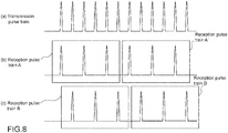
- Reception pulse trains are generated as pulse trains having a plurality of patterns obtained by intermittently integrating a transmission pulse train, and peak values of respective frequencies are obtained. From the difference in peak value between the frequency of the transmission light and the frequency of the reception light, a wind velocity can be obtained on the basis of the Doppler effect.
- the peak values are alternative wind velocity values. If the peak values are equal to each other, they are considered as correct measured values, and if different from each other, it is likely that an erroneous detection of peak values due to noise is included. Therefore, if an absolute value of the difference between the measured values is used as a reliability index, data with high reliability can be selectively used.
- use of reliability information in the airflow measurement allows the weighting of a signal corresponding to reliability and the invalidation of a signal with no reliability, which reduces a possibility of using incorrect data.
- the reliability of the reception signal can be appropriately evaluated.
- Fig. 1 is a block diagram of a configuration of a remote airflow measurement apparatus according to an embodiment of the present invention.
- a remote airflow measurement apparatus 100 includes a measurement unit 10 and a signal processing unit 20.
- the remote airflow measurement apparatus is used to control gust alleviation for an aircraft, it is generally necessary to calculate an airflow vector in the vertical direction, and thus laser light is emitted in a plurality of directions.
- a technique of expanding an airflow vector will not be described here, and thus a diagram simplified for one direction will be used.
- the measurement unit 10 is to emit laser light in a pulse form into the atmosphere, receive reflected light thereof, and measure a wind velocity in an optical-axis direction (emission-axis direction) on the basis of a Doppler shift amount in frequency between the emitted laser light and the reflected light.
- the measurement unit 10 includes an optical telescope 11 and an optical transceiver 12.
- the optical telescope 11 emits laser light (transmission light) generated in the optical transceiver 12 into the atmosphere.
- the emitted laser light is scattered by fine aerosol particles floating in the atmosphere.
- the scattered light is received by the remote airflow measurement apparatus 100 via the optical telescope 11.
- the optical transceiver 12 generates laser light of a single wavelength, for example, 1.5 ⁇ m, and also receives scattered light in the atmosphere and measures a frequency change amount (wavelength change amount) based on the Doppler effect, to thereby measure a wind velocity.
- the frequency change amount based on the Doppler effect is measured by comparing reception light (scattered light) received via the optical telescope 11 with the transmission light.
- the frequency change amount based on the Doppler effect is typically used to measure a wind velocity. This is generally called Doppler lidar.
- Lidar is an abbreviation for "Light Detection And Ranging", that is, a technique for remote observation that uses light.
- the laser light which is a transmission signal
- a reception signal is also a pulse train
- a signal train of the frequency change amount based on the Doppler effect that is, a signal train of a difference between the frequency of the reception signal, which is obtained when a reflected signal of the transmission signal is received, and the frequency of the transmission signal is a pulse train.
- the signal processing unit 20 intermittently integrates the above-mentioned frequency change amount based on the Doppler effect, which is a pulse train, by using two systems to obtain two pieces of integrated data. It is assumed that the number of integration is, for example, 100 to 4000 times.
- the signal processing unit 20 calculates a reliability index of the reception signal by comparison based on the two pieces of integrated data.
- Fig. 2 is a block diagram of a configuration of the signal processing unit 20.
- Fig. 3 is a conceptual diagram for describing that integration is performed using two systems to obtain two pieces of integrated data.
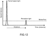
- Fig. 4 is a graph showing a relationship between transmission light (transmission pulse signal) and reception light (reception pulse signal) .
- the signal processing unit 20 includes a first integration unit 21, a Doppler detection unit 22, and a comparator circuit 28 as a reliability index calculation unit.
- the first integration unit 21 intermittently integrates a pulse train corresponding to a reception signal by using two systems and obtains two pieces of integrated data.
- the first integration unit 21 includes a pulse separation circuit 23 and two integrator circuits 24a and 24b.
- the pulse separation circuit 23 inputs the above-mentioned frequency change amount based on the Doppler effect, which is a pulse train, from the measurement unit 10 and separates a reception pulse signal to be integrated in chronological order.
- the pulse separation circuit 23 acquires a reception pulse signal from the measurement unit 10 and generates a reception pulse train A including pulses alternately arranged with respect to the transmission pulse train, and a reception pulse train B shifted from the reception pulse train A by one pulse.
- the integrator circuit 24a integrates the reception pulse train A and calculates integrated data.
- the integrator circuit 24b integrates the reception pulse train B and calculates integrated data.
- the Doppler detection unit 22 divides each of the two pieces of integrated data into a plurality of range bins in time series, obtains a relationship between the frequency and the intensity in each range bin for each of the two pieces of integrated data, and detects a Doppler shift amount from the relationship.
- the Doppler detection unit 22 includes two range division circuits 25a and 25b, two frequency conversion circuits 26a and 26b, and two Doppler detection circuits 27a and 27b.
- each of the range division circuits 25a and 25b divides the reception pulse signal in time series on the basis of the integrated data and specifies a range bin.
- Fig. 4 shows a state of the reception light that is a single reception pulse train with respect to the transmission light that is a single transmission pulse train.
- the wavelength changes are observed for each of the range bins divided in time series, and thus a wind velocity at each position (separation distance) can be measured. Note that a distance having signal intensity equal to or larger than the noise floor is a maximum observation range.
- Each of the frequency conversion circuits 26a and 26b converts the signal in each range bin obtained from each of the range division circuits 25a and 25b, into a frequency, and obtains a relationship between the frequency (wind velocity) and the intensity (power spectral density) of the signal in each range bin.
- Each of the Doppler detection circuits 27a and 27b detects a frequency peak value or the like from the intensity of the signal in each range bin for each frequency, and obtains a Doppler shift amount.
- the comparator circuit 28 calculates a reliability index of the reception signal by comparing the Doppler shift amounts (wind velocity values) output from the two Doppler detection circuits 27a and 27b. Typically, the comparator circuit 28 outputs an absolute value of a difference between the two wind velocity values, as a reliability index.
- a second integrator circuit 201 integrates the two Doppler shift amounts, which are output from the two Doppler detection circuits 27a and 27b, thus allowing an improvement in SNR and accordingly allowing an improvement in measurement accuracy of a wind velocity.
- the second integrator circuit 201 may be mounted on, for example, the signal processing unit 20 configured by hardware, but the second integrator circuit 201 may be configured by software in a control computer 200 of a later stage, because of a small data amount.
- a selection unit that selects a Doppler shift amount having a higher SNR may be employed when the Doppler shift amounts respectively output from the two Doppler detection circuits 27a and 27b are different from each other.
- the Doppler shift amounts (wind velocities V) respectively output from the two Doppler detection circuits 27a and 27b and the reliability index output from the comparator circuit 28 are output from the signal processing unit 20 to the control computer 200 of a later stage.
- data including a wind velocity variance value W (frequency width of signal) and a signal-to-noise ratio (SNR) is output from the signal processing unit 20 to the control computer 200 of a later stage.
- Fig. 5 shows a specific example of an erroneous detection measurement. It is assumed that 1 m/s of the reliability index according to the present invention is set as a threshold for determining incorrect data within a measurement range of ⁇ 40 m/s as shown in the figure.
- An erroneous detection occurs at random frequencies (wind velocities), and thus the probability of successive occurrence of erroneous detections within the range of ⁇ 1 m/s is 1/40.
- the incorrect data can be reduced to 1/40 in this example. From the observation data obtained so far, variations in signal detection are in the range of approximately 0.22 m/s, and thus the threshold of 1 m/s is a realistic value with sufficient margin for preventing correct data from being mistaken for incorrect data.
- the first integration unit 21 intermittently integrates a pulse train corresponding to a reception signal by using two systems and obtains two pieces of integrated data, but the first integration unit 21 may intermittently integrates a pulse train corresponding to a reception signal by using three systems and obtains three pieces of integrated data as shown in Fig. 6 . Alternatively, the first integration unit 21 may obtain more pieces of integrated data. This can further reduce incorrect data.
- a reliability index obtained by the integration divided into three may be a sum or a mean of differences between three values or may be a difference between a minimum value and a maximum value. In the case where two of the three values are close values and the rest is a distant value, the two close values may be integrated to employ the resultant value as a measured value.
- the pulse trains of the respective systems may be integrated intermittently, not at regular intervals.
- the reception pulse trains of the respective systems may have overlapping pulses. This can ease the above-mentioned reduction in number of integration.
- reception pulse trains A and A' are integrated, reception pulse trains B and B' are integrated, and an absolute value of a difference between the obtained results is set as a reliability index; and wind velocity data to be output is obtained from results obtained when the reception pulse trains A and B are integrated and the reception pulse trains A' and B' are integrated. This can improve a sampling rate.
- the reliability index for weighting, for example, it is only necessary to multiply a control gain by the reciprocal of the reliability index. This reciprocal may be multiplied by an appropriate coefficient.
- An actual reception pulse is obtained by receiving light scattered in each range in the atmosphere and thus has a gently sloping shape with respect to the transmission light as shown in Fig. 4 .
- the reception light is divided in time series, and thus a wind velocity can be independently obtained in each range bin.
- a wind velocity can be calculated for the range of 150 km or less because the reciprocating distance of light is approximately 300 km.
- the reception intensity of scattered light is lowered in a long distance, and observation of 30 km or more can be rarely performed.
- the range bin length is, for example, 50 to 300 m.
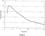
- Fig. 9 shows reception data actually observed. Detectability is obtained by multiplying an SNR of one pulse by the square root of the number of integration times. A high value of the detectability indicates high reception intensity. For example, the reception light in the range of 6 km has a detectability of 5 dB.
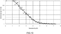
- Fig. 10 shows an example of an actually measured relationship between the detectability and an erroneous signal rate.
- approximately 5% of erroneous signal occurs at the detectability of 5 dB.
- the number of integration is 1/2, and thus the detectability is ⁇ (1/2) times, approximately 3.5 dB.
- the erroneous signal rate is approximately 30% in this case, but if the present invention is applied so as to remove incorrect data on the basis of the reliability index, the incorrect data is reduced to 1/40 as described above. Thus, 0.75% of incorrect data occurs and is dramatically reduced as compared with 5%, which is obtained in the case where the present invention is not applied.
- this example reduces the usage rate of favorable data to 70%. This is because the description is given using a low detectability part for easy understanding of the figure. Actually, a higher detectability part should be used to reduce the rate of incorrect data. Conventionally, the incorrect data has slightly occurred even if the detectability exceeds 7 dB, but applying the present invention allows the incorrect data to be unboundedly brought close to zero.
- control computer 200 is connected to a later stage of the airborne remote airflow measurement apparatus 100.
- the control computer 200 typically controls a control surface 400 by using an autopilot 300.
- the remote airflow measurement apparatus 100 adds a reliability index to a measured wind velocity of each range bin for each of the range bins, and transmits the result to the control computer 200.
- the control computer 200 performs control computation to alleviate a gust of the aircraft in accordance with a change in wind velocity and transmits a lift control signal to the autopilot 300. At that time, if the reliability of measurement is low in accordance with the reliability index, the control computer 200 controls the autopilot 300 to reduce a control gain or stop controlling the control surface.
- the autopilot 300 optimally operates the control surface 400 in accordance with the specifications of the aircraft.
- the Doppler lidar is characterized by being capable of remote airflow observation even in clear weather, but the Doppler lidar has a short effective observation range, which is pointed out by pilots of airline companies and is a heavy drag on practical use of the Doppler lidar. However, even with a short effective observation range of approximately 500 m, if the control surface is automatically controlled to alleviate a gust of the aircraft, turbulence-induced accidents can be prevented. Applying the remote airflow measurement apparatus including the signal processing device according to the present invention allows an improvement in measurement reliability for forward airflow information and allows such airflow information, which serves as prior information for automatically controlling the control surface, to be applied to passenger airplanes.
- the present invention is not limited to the embodiments described above and can be variously modified and implemented.
- the range of the implementation belongs to the range of the technical idea of the present invention.
- the airborne remote airflow measurement apparatus including the signal processing device according to the present invention has been described as an example, but the remote airflow measurement apparatus including the signal processing device according to the present invention may be a ground apparatus.
- the remote airflow measurement apparatus including the signal processing device according to the present invention is also applicable to not only a Doppler lidar using light waves but also a Doppler radar using radio waves or a Doppler sodar using sound waves.
- a reception unit 4 including a plurality of receiving elements 4a receives a signal output from a transmission source 3.
- Two integrator circuits 5a and 5b receive the signals from the receiving elements 4a and obtain pieces of integrated data of the two systems.
- the two integrator circuits 5a and 5b each integrate the reception signals in different combinations, and a determination circuit 6 calculates a reliability index of the reception signals by comparison based on the pieces of integrated data of the two systems and eliminates information with low reliability, thus allowing an improvement in reception quality.
- the receiving elements 4a may be antennas for radio waves, microphones, or imaging devices. If real-time processing is unnecessary, the combinations of integration may be changed to maximize available information.
- the above embodiments have described the pulse train as an example. However, in this case, time-varying signal values are also comparable, and thus the reception signal does not need to be a pulse.
- the present invention is also applicable to a distance meter and the like.
- the distance meter only needs to have a high pulse rate and low pulse energy while having the same principle as a normal laser distance meter, and thus a small high-efficiency laser diode can be used without amplification.
- the pulse rate is 100 kHz and the pulse energy is 10 ⁇ J
- the output of 1 W on average is obtained, and information of a distance up to 1.5 km can be output in a period of 50 Hz, for example.
- the present invention can be used for proximity sensors for vehicles, ships, satellites, and the like.
- the transmission light and the reception light have a one-to-one relationship, which does not need distance division or frequency measurement. It is only necessary to integrate the reception light by two integrator circuits, calculate a reliability index by comparison of those integrations, and remove information with low reliability.
Landscapes
- Engineering & Computer Science (AREA)
- Physics & Mathematics (AREA)
- Radar, Positioning & Navigation (AREA)
- Remote Sensing (AREA)
- Computer Networks & Wireless Communication (AREA)
- General Physics & Mathematics (AREA)
- Electromagnetism (AREA)
- Aviation & Aerospace Engineering (AREA)
- Automation & Control Theory (AREA)
- Optical Radar Systems And Details Thereof (AREA)
- Investigating Or Analysing Materials By Optical Means (AREA)
- Radar Systems Or Details Thereof (AREA)
- Measurement Of Velocity Or Position Using Acoustic Or Ultrasonic Waves (AREA)
Applications Claiming Priority (2)
| Application Number | Priority Date | Filing Date | Title |
|---|---|---|---|
| JP2017234165A JP7051081B2 (ja) | 2017-12-06 | 2017-12-06 | 信号処理装置及び信号処理方法 |
| PCT/JP2018/041995 WO2019111654A1 (ja) | 2017-12-06 | 2018-11-13 | 信号処理装置及び信号処理方法 |
Publications (3)
| Publication Number | Publication Date |
|---|---|
| EP3722828A1 true EP3722828A1 (de) | 2020-10-14 |
| EP3722828A4 EP3722828A4 (de) | 2021-09-01 |
| EP3722828B1 EP3722828B1 (de) | 2024-01-17 |
Family
ID=66750958
Family Applications (1)
| Application Number | Title | Priority Date | Filing Date |
|---|---|---|---|
| EP18885414.5A Active EP3722828B1 (de) | 2017-12-06 | 2018-11-13 | Signalverarbeitungsvorrichtung und signalverarbeitungsverfahren |
Country Status (4)
| Country | Link |
|---|---|
| US (1) | US11796655B2 (de) |
| EP (1) | EP3722828B1 (de) |
| JP (1) | JP7051081B2 (de) |
| WO (1) | WO2019111654A1 (de) |
Families Citing this family (4)
| Publication number | Priority date | Publication date | Assignee | Title |
|---|---|---|---|---|
| JP7336134B2 (ja) * | 2019-08-08 | 2023-08-31 | 国立研究開発法人宇宙航空研究開発機構 | 遠隔気流観測装置、遠隔気流観測方法及びプログラム |
| JP7816364B2 (ja) * | 2021-09-24 | 2026-02-18 | 日本電気株式会社 | 領域特定システム、領域特定方法及び領域特定プログラム |
| JP2024035272A (ja) * | 2022-09-02 | 2024-03-14 | 国立研究開発法人宇宙航空研究開発機構 | 航空機の自動制御システム、その有効性評価方法およびその自動制御システム用の計測装置 |
| WO2025043201A1 (en) * | 2023-08-24 | 2025-02-27 | University Of Cincinnati | Systems and methods for aerial vehicles equipped with control moment gyroscopes |
Family Cites Families (19)
| Publication number | Priority date | Publication date | Assignee | Title |
|---|---|---|---|---|
| JPH01152382A (ja) * | 1987-12-10 | 1989-06-14 | Nec Corp | レベル判定装置 |
| ATE202635T1 (de) * | 1995-03-03 | 2001-07-15 | Siemens Ag | Verfahren und anordnung zur verkehrserfassung mit einem radargerät |
| JP2720848B2 (ja) * | 1995-10-13 | 1998-03-04 | 日本電気株式会社 | 二次監視レーダ目標検出装置 |
| JP3335832B2 (ja) * | 1996-02-05 | 2002-10-21 | 株式会社東芝 | レーダ受信装置 |
| JP4268695B2 (ja) | 1997-10-31 | 2009-05-27 | 株式会社東芝 | 画像診断装置及び超音波診断装置 |
| JP2002311130A (ja) * | 2001-04-10 | 2002-10-23 | Nissan Motor Co Ltd | 車両用レーダ装置 |
| JP4329442B2 (ja) * | 2003-07-30 | 2009-09-09 | 日産自動車株式会社 | 周辺車両検出装置 |
| JP4392409B2 (ja) * | 2004-02-09 | 2010-01-06 | アンリツ株式会社 | レーダ装置 |
| JP4806949B2 (ja) | 2005-03-31 | 2011-11-02 | 三菱電機株式会社 | レーザレーダ装置 |
| US7933612B2 (en) * | 2006-02-28 | 2011-04-26 | Microsoft Corporation | Determining physical location based upon received signals |
| JP5252696B2 (ja) | 2008-06-11 | 2013-07-31 | 独立行政法人 宇宙航空研究開発機構 | 航空機搭載用光学式遠隔気流計測装置 |
| JP5771893B2 (ja) | 2009-11-20 | 2015-09-02 | 国立研究開発法人宇宙航空研究開発機構 | 乱気流抑制制御方法 |
| JP5398001B2 (ja) | 2009-12-07 | 2014-01-29 | 独立行政法人 宇宙航空研究開発機構 | 航空機搭載用乱気流事故防止装置 |
| JP5881099B2 (ja) | 2011-10-06 | 2016-03-09 | 国立研究開発法人宇宙航空研究開発機構 | 光学式遠隔気流計測装置の有色ノイズ低減方法とその装置 |
| US9575184B2 (en) * | 2014-07-03 | 2017-02-21 | Continental Advanced Lidar Solutions Us, Inc. | LADAR sensor for a dense environment |
| WO2016125399A1 (ja) * | 2015-02-02 | 2016-08-11 | 古野電気株式会社 | 探知装置、および、探知方法 |
| JP6583677B2 (ja) * | 2015-10-01 | 2019-10-02 | 国立研究開発法人宇宙航空研究開発機構 | 遠隔気流計測装置、遠隔気流計測方法及びプログラム |
| US10416292B2 (en) * | 2016-05-24 | 2019-09-17 | Veoneer Us, Inc. | Direct detection LiDAR system and method with frequency modulation (FM) transmitter and quadrature receiver |
| KR101807522B1 (ko) * | 2016-06-29 | 2017-12-12 | 재단법인대구경북과학기술원 | 자기 간섭을 이용한 레이더의 수신 채널 보상 장치 및 그 방법 |
-
2017
- 2017-12-06 JP JP2017234165A patent/JP7051081B2/ja active Active
-
2018
- 2018-11-13 US US16/769,447 patent/US11796655B2/en active Active
- 2018-11-13 EP EP18885414.5A patent/EP3722828B1/de active Active
- 2018-11-13 WO PCT/JP2018/041995 patent/WO2019111654A1/ja not_active Ceased
Also Published As
| Publication number | Publication date |
|---|---|
| US11796655B2 (en) | 2023-10-24 |
| US20200371218A1 (en) | 2020-11-26 |
| JP2019100943A (ja) | 2019-06-24 |
| JP7051081B2 (ja) | 2022-04-11 |
| EP3722828B1 (de) | 2024-01-17 |
| EP3722828A4 (de) | 2021-09-01 |
| WO2019111654A1 (ja) | 2019-06-13 |
Similar Documents
| Publication | Publication Date | Title |
|---|---|---|
| EP3722828B1 (de) | Signalverarbeitungsvorrichtung und signalverarbeitungsverfahren | |
| KR101240629B1 (ko) | Ads-b 시스템이 탑재된 항공기를 이용한 미지신호 검출 및 발생원 위치 추정방법 | |
| US9019481B2 (en) | Colored noise reduction method and device for optical remote airflow measurement apparatus | |
| CN108802715B (zh) | 一种数字化脉冲体制的无线电高度表 | |
| JP6901713B2 (ja) | ライダ及びライダにおける信号処理方法 | |
| JP6244862B2 (ja) | レーザレーダ装置 | |
| JP6624601B2 (ja) | レーダ装置および目標物体検出方法 | |
| JPH10227853A (ja) | レーダ装置及びそのレーダ信号処理方法 | |
| AU2010262765A1 (en) | Characterisation of a wireless communications link | |
| JP7369822B2 (ja) | 多波長ドップラー・ライダー | |
| KR20110041464A (ko) | 항공기의 식별방법, 및 그것을 사용한 항공기 소음의 측정방법 및 신호 판정방법, 항공기의 식별장치 | |
| CA2095367C (en) | Passive aircraft monitoring system | |
| KR20080024119A (ko) | 항공기용 무선 시스템 | |
| CN107831492B (zh) | 一种机载风切变仪及风切变探测方法 | |
| CA2593436A1 (en) | Dual beam radar system | |
| JP2006284260A (ja) | レーザレーダ装置 | |
| EP3985417B1 (de) | Vorrichtung und verfahren zur beobachtung eines entfernten luftstroms und programm | |
| Żywek et al. | Real-time selection of FM transmitter in passive bistatic radar based on short-term bandwidth analysis | |
| US8902101B1 (en) | System for and method of wind shear detection | |
| CN111220982A (zh) | 一种机载晴空颠簸探测仪及其工作方法 | |
| JP3414316B2 (ja) | 航空機監視装置 | |
| KR101619064B1 (ko) | 능동 클러터 맵을 이용한 목표물 검출 방법 | |
| KR20220170767A (ko) | 레이더-라이다 센서의 융합 장치 및 이를 이용한 표적 탐지 방법 | |
| Inokuchi et al. | Development of an airborne wind measurement system | |
| KR100989097B1 (ko) | 비행체 고도 측정 장치 및 방법 |
Legal Events
| Date | Code | Title | Description |
|---|---|---|---|
| STAA | Information on the status of an ep patent application or granted ep patent |
Free format text: STATUS: THE INTERNATIONAL PUBLICATION HAS BEEN MADE |
|
| PUAI | Public reference made under article 153(3) epc to a published international application that has entered the european phase |
Free format text: ORIGINAL CODE: 0009012 |
|
| STAA | Information on the status of an ep patent application or granted ep patent |
Free format text: STATUS: REQUEST FOR EXAMINATION WAS MADE |
|
| 17P | Request for examination filed |
Effective date: 20200703 |
|
| AK | Designated contracting states |
Kind code of ref document: A1 Designated state(s): AL AT BE BG CH CY CZ DE DK EE ES FI FR GB GR HR HU IE IS IT LI LT LU LV MC MK MT NL NO PL PT RO RS SE SI SK SM TR |
|
| AX | Request for extension of the european patent |
Extension state: BA ME |
|
| DAV | Request for validation of the european patent (deleted) | ||
| DAX | Request for extension of the european patent (deleted) | ||
| A4 | Supplementary search report drawn up and despatched |
Effective date: 20210730 |
|
| RIC1 | Information provided on ipc code assigned before grant |
Ipc: G01S 7/497 20060101AFI20210726BHEP Ipc: G01S 7/40 20060101ALI20210726BHEP Ipc: G01S 13/58 20060101ALI20210726BHEP Ipc: G01S 13/95 20060101ALI20210726BHEP Ipc: G01S 15/58 20060101ALI20210726BHEP Ipc: G01S 17/58 20060101ALI20210726BHEP Ipc: G01S 17/95 20060101ALI20210726BHEP Ipc: B64D 45/00 20060101ALI20210726BHEP |
|
| GRAP | Despatch of communication of intention to grant a patent |
Free format text: ORIGINAL CODE: EPIDOSNIGR1 |
|
| STAA | Information on the status of an ep patent application or granted ep patent |
Free format text: STATUS: GRANT OF PATENT IS INTENDED |
|
| INTG | Intention to grant announced |
Effective date: 20230831 |
|
| GRAS | Grant fee paid |
Free format text: ORIGINAL CODE: EPIDOSNIGR3 |
|
| GRAA | (expected) grant |
Free format text: ORIGINAL CODE: 0009210 |
|
| STAA | Information on the status of an ep patent application or granted ep patent |
Free format text: STATUS: THE PATENT HAS BEEN GRANTED |
|
| AK | Designated contracting states |
Kind code of ref document: B1 Designated state(s): AL AT BE BG CH CY CZ DE DK EE ES FI FR GB GR HR HU IE IS IT LI LT LU LV MC MK MT NL NO PL PT RO RS SE SI SK SM TR |
|
| REG | Reference to a national code |
Ref country code: GB Ref legal event code: FG4D |
|
| REG | Reference to a national code |
Ref country code: DE Ref legal event code: R096 Ref document number: 602018064366 Country of ref document: DE |
|
| REG | Reference to a national code |
Ref country code: CH Ref legal event code: EP |
|
| REG | Reference to a national code |
Ref country code: IE Ref legal event code: FG4D |
|
| REG | Reference to a national code |
Ref country code: LT Ref legal event code: MG9D |
|
| REG | Reference to a national code |
Ref country code: NL Ref legal event code: MP Effective date: 20240117 |
|
| REG | Reference to a national code |
Ref country code: AT Ref legal event code: MK05 Ref document number: 1650883 Country of ref document: AT Kind code of ref document: T Effective date: 20240117 |
|
| PG25 | Lapsed in a contracting state [announced via postgrant information from national office to epo] |
Ref country code: NL Free format text: LAPSE BECAUSE OF FAILURE TO SUBMIT A TRANSLATION OF THE DESCRIPTION OR TO PAY THE FEE WITHIN THE PRESCRIBED TIME-LIMIT Effective date: 20240117 |
|
| PG25 | Lapsed in a contracting state [announced via postgrant information from national office to epo] |
Ref country code: NL Free format text: LAPSE BECAUSE OF FAILURE TO SUBMIT A TRANSLATION OF THE DESCRIPTION OR TO PAY THE FEE WITHIN THE PRESCRIBED TIME-LIMIT Effective date: 20240117 |
|
| PG25 | Lapsed in a contracting state [announced via postgrant information from national office to epo] |
Ref country code: IS Free format text: LAPSE BECAUSE OF FAILURE TO SUBMIT A TRANSLATION OF THE DESCRIPTION OR TO PAY THE FEE WITHIN THE PRESCRIBED TIME-LIMIT Effective date: 20240517 |
|
| PG25 | Lapsed in a contracting state [announced via postgrant information from national office to epo] |
Ref country code: LT Free format text: LAPSE BECAUSE OF FAILURE TO SUBMIT A TRANSLATION OF THE DESCRIPTION OR TO PAY THE FEE WITHIN THE PRESCRIBED TIME-LIMIT Effective date: 20240117 |
|
| PG25 | Lapsed in a contracting state [announced via postgrant information from national office to epo] |
Ref country code: GR Free format text: LAPSE BECAUSE OF FAILURE TO SUBMIT A TRANSLATION OF THE DESCRIPTION OR TO PAY THE FEE WITHIN THE PRESCRIBED TIME-LIMIT Effective date: 20240418 |
|
| PG25 | Lapsed in a contracting state [announced via postgrant information from national office to epo] |
Ref country code: HR Free format text: LAPSE BECAUSE OF FAILURE TO SUBMIT A TRANSLATION OF THE DESCRIPTION OR TO PAY THE FEE WITHIN THE PRESCRIBED TIME-LIMIT Effective date: 20240117 Ref country code: RS Free format text: LAPSE BECAUSE OF FAILURE TO SUBMIT A TRANSLATION OF THE DESCRIPTION OR TO PAY THE FEE WITHIN THE PRESCRIBED TIME-LIMIT Effective date: 20240417 |
|
| PG25 | Lapsed in a contracting state [announced via postgrant information from national office to epo] |
Ref country code: ES Free format text: LAPSE BECAUSE OF FAILURE TO SUBMIT A TRANSLATION OF THE DESCRIPTION OR TO PAY THE FEE WITHIN THE PRESCRIBED TIME-LIMIT Effective date: 20240117 |
|
| PG25 | Lapsed in a contracting state [announced via postgrant information from national office to epo] |
Ref country code: AT Free format text: LAPSE BECAUSE OF FAILURE TO SUBMIT A TRANSLATION OF THE DESCRIPTION OR TO PAY THE FEE WITHIN THE PRESCRIBED TIME-LIMIT Effective date: 20240117 |
|
| PG25 | Lapsed in a contracting state [announced via postgrant information from national office to epo] |
Ref country code: RS Free format text: LAPSE BECAUSE OF FAILURE TO SUBMIT A TRANSLATION OF THE DESCRIPTION OR TO PAY THE FEE WITHIN THE PRESCRIBED TIME-LIMIT Effective date: 20240417 Ref country code: NO Free format text: LAPSE BECAUSE OF FAILURE TO SUBMIT A TRANSLATION OF THE DESCRIPTION OR TO PAY THE FEE WITHIN THE PRESCRIBED TIME-LIMIT Effective date: 20240417 Ref country code: LT Free format text: LAPSE BECAUSE OF FAILURE TO SUBMIT A TRANSLATION OF THE DESCRIPTION OR TO PAY THE FEE WITHIN THE PRESCRIBED TIME-LIMIT Effective date: 20240117 Ref country code: IS Free format text: LAPSE BECAUSE OF FAILURE TO SUBMIT A TRANSLATION OF THE DESCRIPTION OR TO PAY THE FEE WITHIN THE PRESCRIBED TIME-LIMIT Effective date: 20240517 Ref country code: HR Free format text: LAPSE BECAUSE OF FAILURE TO SUBMIT A TRANSLATION OF THE DESCRIPTION OR TO PAY THE FEE WITHIN THE PRESCRIBED TIME-LIMIT Effective date: 20240117 Ref country code: GR Free format text: LAPSE BECAUSE OF FAILURE TO SUBMIT A TRANSLATION OF THE DESCRIPTION OR TO PAY THE FEE WITHIN THE PRESCRIBED TIME-LIMIT Effective date: 20240418 Ref country code: FI Free format text: LAPSE BECAUSE OF FAILURE TO SUBMIT A TRANSLATION OF THE DESCRIPTION OR TO PAY THE FEE WITHIN THE PRESCRIBED TIME-LIMIT Effective date: 20240117 Ref country code: ES Free format text: LAPSE BECAUSE OF FAILURE TO SUBMIT A TRANSLATION OF THE DESCRIPTION OR TO PAY THE FEE WITHIN THE PRESCRIBED TIME-LIMIT Effective date: 20240117 Ref country code: BG Free format text: LAPSE BECAUSE OF FAILURE TO SUBMIT A TRANSLATION OF THE DESCRIPTION OR TO PAY THE FEE WITHIN THE PRESCRIBED TIME-LIMIT Effective date: 20240117 Ref country code: AT Free format text: LAPSE BECAUSE OF FAILURE TO SUBMIT A TRANSLATION OF THE DESCRIPTION OR TO PAY THE FEE WITHIN THE PRESCRIBED TIME-LIMIT Effective date: 20240117 |
|
| PG25 | Lapsed in a contracting state [announced via postgrant information from national office to epo] |
Ref country code: PL Free format text: LAPSE BECAUSE OF FAILURE TO SUBMIT A TRANSLATION OF THE DESCRIPTION OR TO PAY THE FEE WITHIN THE PRESCRIBED TIME-LIMIT Effective date: 20240117 Ref country code: PT Free format text: LAPSE BECAUSE OF FAILURE TO SUBMIT A TRANSLATION OF THE DESCRIPTION OR TO PAY THE FEE WITHIN THE PRESCRIBED TIME-LIMIT Effective date: 20240517 |
|
| PG25 | Lapsed in a contracting state [announced via postgrant information from national office to epo] |
Ref country code: SE Free format text: LAPSE BECAUSE OF FAILURE TO SUBMIT A TRANSLATION OF THE DESCRIPTION OR TO PAY THE FEE WITHIN THE PRESCRIBED TIME-LIMIT Effective date: 20240117 Ref country code: PT Free format text: LAPSE BECAUSE OF FAILURE TO SUBMIT A TRANSLATION OF THE DESCRIPTION OR TO PAY THE FEE WITHIN THE PRESCRIBED TIME-LIMIT Effective date: 20240517 Ref country code: PL Free format text: LAPSE BECAUSE OF FAILURE TO SUBMIT A TRANSLATION OF THE DESCRIPTION OR TO PAY THE FEE WITHIN THE PRESCRIBED TIME-LIMIT Effective date: 20240117 Ref country code: LV Free format text: LAPSE BECAUSE OF FAILURE TO SUBMIT A TRANSLATION OF THE DESCRIPTION OR TO PAY THE FEE WITHIN THE PRESCRIBED TIME-LIMIT Effective date: 20240117 |
|
| PG25 | Lapsed in a contracting state [announced via postgrant information from national office to epo] |
Ref country code: DK Free format text: LAPSE BECAUSE OF FAILURE TO SUBMIT A TRANSLATION OF THE DESCRIPTION OR TO PAY THE FEE WITHIN THE PRESCRIBED TIME-LIMIT Effective date: 20240117 |
|
| PG25 | Lapsed in a contracting state [announced via postgrant information from national office to epo] |
Ref country code: SM Free format text: LAPSE BECAUSE OF FAILURE TO SUBMIT A TRANSLATION OF THE DESCRIPTION OR TO PAY THE FEE WITHIN THE PRESCRIBED TIME-LIMIT Effective date: 20240117 |
|
| REG | Reference to a national code |
Ref country code: DE Ref legal event code: R097 Ref document number: 602018064366 Country of ref document: DE |
|
| PG25 | Lapsed in a contracting state [announced via postgrant information from national office to epo] |
Ref country code: CZ Free format text: LAPSE BECAUSE OF FAILURE TO SUBMIT A TRANSLATION OF THE DESCRIPTION OR TO PAY THE FEE WITHIN THE PRESCRIBED TIME-LIMIT Effective date: 20240117 Ref country code: EE Free format text: LAPSE BECAUSE OF FAILURE TO SUBMIT A TRANSLATION OF THE DESCRIPTION OR TO PAY THE FEE WITHIN THE PRESCRIBED TIME-LIMIT Effective date: 20240117 |
|
| PG25 | Lapsed in a contracting state [announced via postgrant information from national office to epo] |
Ref country code: SK Free format text: LAPSE BECAUSE OF FAILURE TO SUBMIT A TRANSLATION OF THE DESCRIPTION OR TO PAY THE FEE WITHIN THE PRESCRIBED TIME-LIMIT Effective date: 20240117 |
|
| PG25 | Lapsed in a contracting state [announced via postgrant information from national office to epo] |
Ref country code: SM Free format text: LAPSE BECAUSE OF FAILURE TO SUBMIT A TRANSLATION OF THE DESCRIPTION OR TO PAY THE FEE WITHIN THE PRESCRIBED TIME-LIMIT Effective date: 20240117 Ref country code: SK Free format text: LAPSE BECAUSE OF FAILURE TO SUBMIT A TRANSLATION OF THE DESCRIPTION OR TO PAY THE FEE WITHIN THE PRESCRIBED TIME-LIMIT Effective date: 20240117 Ref country code: RO Free format text: LAPSE BECAUSE OF FAILURE TO SUBMIT A TRANSLATION OF THE DESCRIPTION OR TO PAY THE FEE WITHIN THE PRESCRIBED TIME-LIMIT Effective date: 20240117 Ref country code: EE Free format text: LAPSE BECAUSE OF FAILURE TO SUBMIT A TRANSLATION OF THE DESCRIPTION OR TO PAY THE FEE WITHIN THE PRESCRIBED TIME-LIMIT Effective date: 20240117 Ref country code: DK Free format text: LAPSE BECAUSE OF FAILURE TO SUBMIT A TRANSLATION OF THE DESCRIPTION OR TO PAY THE FEE WITHIN THE PRESCRIBED TIME-LIMIT Effective date: 20240117 Ref country code: CZ Free format text: LAPSE BECAUSE OF FAILURE TO SUBMIT A TRANSLATION OF THE DESCRIPTION OR TO PAY THE FEE WITHIN THE PRESCRIBED TIME-LIMIT Effective date: 20240117 |
|
| PLBE | No opposition filed within time limit |
Free format text: ORIGINAL CODE: 0009261 |
|
| STAA | Information on the status of an ep patent application or granted ep patent |
Free format text: STATUS: NO OPPOSITION FILED WITHIN TIME LIMIT |
|
| PG25 | Lapsed in a contracting state [announced via postgrant information from national office to epo] |
Ref country code: IT Free format text: LAPSE BECAUSE OF FAILURE TO SUBMIT A TRANSLATION OF THE DESCRIPTION OR TO PAY THE FEE WITHIN THE PRESCRIBED TIME-LIMIT Effective date: 20240117 |
|
| 26N | No opposition filed |
Effective date: 20241018 |
|
| PG25 | Lapsed in a contracting state [announced via postgrant information from national office to epo] |
Ref country code: IT Free format text: LAPSE BECAUSE OF FAILURE TO SUBMIT A TRANSLATION OF THE DESCRIPTION OR TO PAY THE FEE WITHIN THE PRESCRIBED TIME-LIMIT Effective date: 20240117 |
|
| PG25 | Lapsed in a contracting state [announced via postgrant information from national office to epo] |
Ref country code: SI Free format text: LAPSE BECAUSE OF FAILURE TO SUBMIT A TRANSLATION OF THE DESCRIPTION OR TO PAY THE FEE WITHIN THE PRESCRIBED TIME-LIMIT Effective date: 20240117 |
|
| REG | Reference to a national code |
Ref country code: CH Ref legal event code: PL |
|
| PG25 | Lapsed in a contracting state [announced via postgrant information from national office to epo] |
Ref country code: MC Free format text: LAPSE BECAUSE OF FAILURE TO SUBMIT A TRANSLATION OF THE DESCRIPTION OR TO PAY THE FEE WITHIN THE PRESCRIBED TIME-LIMIT Effective date: 20240117 |
|
| PG25 | Lapsed in a contracting state [announced via postgrant information from national office to epo] |
Ref country code: LU Free format text: LAPSE BECAUSE OF NON-PAYMENT OF DUE FEES Effective date: 20241113 |
|
| REG | Reference to a national code |
Ref country code: CH Ref legal event code: PL |
|
| GBPC | Gb: european patent ceased through non-payment of renewal fee |
Effective date: 20241113 |
|
| PG25 | Lapsed in a contracting state [announced via postgrant information from national office to epo] |
Ref country code: CH Free format text: LAPSE BECAUSE OF NON-PAYMENT OF DUE FEES Effective date: 20241130 |
|
| REG | Reference to a national code |
Ref country code: BE Ref legal event code: MM Effective date: 20241130 |
|
| PG25 | Lapsed in a contracting state [announced via postgrant information from national office to epo] |
Ref country code: GB Free format text: LAPSE BECAUSE OF NON-PAYMENT OF DUE FEES Effective date: 20241113 Ref country code: BE Free format text: LAPSE BECAUSE OF NON-PAYMENT OF DUE FEES Effective date: 20241130 |
|
| PG25 | Lapsed in a contracting state [announced via postgrant information from national office to epo] |
Ref country code: IE Free format text: LAPSE BECAUSE OF NON-PAYMENT OF DUE FEES Effective date: 20241113 |
|
| PGFP | Annual fee paid to national office [announced via postgrant information from national office to epo] |
Ref country code: DE Payment date: 20251119 Year of fee payment: 8 |
|
| PGFP | Annual fee paid to national office [announced via postgrant information from national office to epo] |
Ref country code: FR Payment date: 20251126 Year of fee payment: 8 |
|
| PG25 | Lapsed in a contracting state [announced via postgrant information from national office to epo] |
Ref country code: HU Free format text: LAPSE BECAUSE OF FAILURE TO SUBMIT A TRANSLATION OF THE DESCRIPTION OR TO PAY THE FEE WITHIN THE PRESCRIBED TIME-LIMIT; INVALID AB INITIO Effective date: 20181113 |
|
| PG25 | Lapsed in a contracting state [announced via postgrant information from national office to epo] |
Ref country code: CY Free format text: LAPSE BECAUSE OF FAILURE TO SUBMIT A TRANSLATION OF THE DESCRIPTION OR TO PAY THE FEE WITHIN THE PRESCRIBED TIME-LIMIT; INVALID AB INITIO Effective date: 20181113 |