EP3722831A1 - Verfahren zur drahtlosen entfernungsmessung - Google Patents
Verfahren zur drahtlosen entfernungsmessung Download PDFInfo
- Publication number
- EP3722831A1 EP3722831A1 EP19168443.0A EP19168443A EP3722831A1 EP 3722831 A1 EP3722831 A1 EP 3722831A1 EP 19168443 A EP19168443 A EP 19168443A EP 3722831 A1 EP3722831 A1 EP 3722831A1
- Authority
- EP
- European Patent Office
- Prior art keywords
- node
- initiator
- responder
- clock reference
- nominal
- Prior art date
- Legal status (The legal status is an assumption and is not a legal conclusion. Google has not performed a legal analysis and makes no representation as to the accuracy of the status listed.)
- Pending
Links
Images


Classifications
-
- G—PHYSICS
- G01—MEASURING; TESTING
- G01S—RADIO DIRECTION-FINDING; RADIO NAVIGATION; DETERMINING DISTANCE OR VELOCITY BY USE OF RADIO WAVES; LOCATING OR PRESENCE-DETECTING BY USE OF THE REFLECTION OR RERADIATION OF RADIO WAVES; ANALOGOUS ARRANGEMENTS USING OTHER WAVES
- G01S5/00—Position-fixing by co-ordinating two or more direction or position line determinations; Position-fixing by co-ordinating two or more distance determinations
- G01S5/02—Position-fixing by co-ordinating two or more direction or position line determinations; Position-fixing by co-ordinating two or more distance determinations using radio waves
- G01S5/0246—Position-fixing by co-ordinating two or more direction or position line determinations; Position-fixing by co-ordinating two or more distance determinations using radio waves involving frequency difference of arrival or Doppler measurements
-
- G—PHYSICS
- G01—MEASURING; TESTING
- G01S—RADIO DIRECTION-FINDING; RADIO NAVIGATION; DETERMINING DISTANCE OR VELOCITY BY USE OF RADIO WAVES; LOCATING OR PRESENCE-DETECTING BY USE OF THE REFLECTION OR RERADIATION OF RADIO WAVES; ANALOGOUS ARRANGEMENTS USING OTHER WAVES
- G01S13/00—Systems using the reflection or reradiation of radio waves, e.g. radar systems; Analogous systems using reflection or reradiation of waves whose nature or wavelength is irrelevant or unspecified
- G01S13/74—Systems using reradiation of radio waves, e.g. secondary radar systems; Analogous systems
- G01S13/82—Systems using reradiation of radio waves, e.g. secondary radar systems; Analogous systems wherein continuous-type signals are transmitted
- G01S13/84—Systems using reradiation of radio waves, e.g. secondary radar systems; Analogous systems wherein continuous-type signals are transmitted for distance determination by phase measurement
-
- G—PHYSICS
- G01—MEASURING; TESTING
- G01S—RADIO DIRECTION-FINDING; RADIO NAVIGATION; DETERMINING DISTANCE OR VELOCITY BY USE OF RADIO WAVES; LOCATING OR PRESENCE-DETECTING BY USE OF THE REFLECTION OR RERADIATION OF RADIO WAVES; ANALOGOUS ARRANGEMENTS USING OTHER WAVES
- G01S5/00—Position-fixing by co-ordinating two or more direction or position line determinations; Position-fixing by co-ordinating two or more distance determinations
- G01S5/02—Position-fixing by co-ordinating two or more direction or position line determinations; Position-fixing by co-ordinating two or more distance determinations using radio waves
- G01S5/0205—Details
- G01S5/0221—Receivers
- G01S5/02213—Receivers arranged in a network for determining the position of a transmitter
- G01S5/02216—Timing or synchronisation of the receivers
-
- G—PHYSICS
- G01—MEASURING; TESTING
- G01S—RADIO DIRECTION-FINDING; RADIO NAVIGATION; DETERMINING DISTANCE OR VELOCITY BY USE OF RADIO WAVES; LOCATING OR PRESENCE-DETECTING BY USE OF THE REFLECTION OR RERADIATION OF RADIO WAVES; ANALOGOUS ARRANGEMENTS USING OTHER WAVES
- G01S5/00—Position-fixing by co-ordinating two or more direction or position line determinations; Position-fixing by co-ordinating two or more distance determinations
- G01S5/02—Position-fixing by co-ordinating two or more direction or position line determinations; Position-fixing by co-ordinating two or more distance determinations using radio waves
- G01S5/0257—Hybrid positioning
- G01S5/0268—Hybrid positioning by deriving positions from different combinations of signals or of estimated positions in a single positioning system
- G01S5/02685—Hybrid positioning by deriving positions from different combinations of signals or of estimated positions in a single positioning system involving dead reckoning based on radio wave measurements
-
- G—PHYSICS
- G01—MEASURING; TESTING
- G01S—RADIO DIRECTION-FINDING; RADIO NAVIGATION; DETERMINING DISTANCE OR VELOCITY BY USE OF RADIO WAVES; LOCATING OR PRESENCE-DETECTING BY USE OF THE REFLECTION OR RERADIATION OF RADIO WAVES; ANALOGOUS ARRANGEMENTS USING OTHER WAVES
- G01S5/00—Position-fixing by co-ordinating two or more direction or position line determinations; Position-fixing by co-ordinating two or more distance determinations
- G01S5/02—Position-fixing by co-ordinating two or more direction or position line determinations; Position-fixing by co-ordinating two or more distance determinations using radio waves
- G01S5/0284—Relative positioning
Definitions
- the present inventive concept relates to methods and devices for wireless ranging.
- Ranging involves determining the distances between wireless nodes.
- Multi-carrier Phase Difference Ranging is a known method used to estimate the distance between two wireless nodes based on phase difference of two or more carrier signals. It may be implemented in narrowband systems like Bluetooth, Bluetooth Low Energy (BLE), IEEE 802.15.4 (e.g., Zigbee), and others. An example implementation of such a method is disclosed in W. Kluge and D. Eggert, "Ranging with IEEE 802.15.4 narrowband PHY", IEEE P802.15 Working Group for Wireless Personal Area Networks (WPANs), September 2009, https://mentor.ieee.org/802.15/dcn/1915-09-0613-01-004franging-with-ieee-802-15-4-narrow-band-phy.ppt .
- An objective of the present inventive concept is to provide methods and devices for wireless ranging with improved accuracy.
- a method of wireless ranging between an initiator node and a responder node comprising, for each nominal frequency in a plurality of nominal frequencies, performing a measurement procedure resulting in a two-way phase measurement between the initiator node the responder node, the measurement procedure comprising the initiator node transmitting an initiator carrier signal, the frequency of the initiator carrier signal being derived from an initiator node clock reference; the responder node performing a phase measurement of the initiator carrier signal relative to a responder node clock reference; the responder node transmitting a responder carrier signal, the frequency of the initiator carrier signal being derived from the responder clock reference; and the initiator node performing a phase measurement of the responder carrier signal relative to the initiator node clock reference, the method further comprising calculating a distance between the initiator node and the responder node using as input the two-way phase measurements for the plurality of nominal frequencies; and a clock reference offset correction of the initiator node
- carrier signal should be understood a continuous-wave sinusoidal oscillation with a single frequency-component (neglecting harmonics and other imperfections). Such a signal may typically originate directly from the local oscillator (LO) of the transmitting node. However, as an example, it can also be obtained by applying a constant modulation, such as a frequency shift keying (FSK) modulation with a constant input (all 1s or 0s).
- LO local oscillator
- FSK frequency shift keying
- initiator node and "responder node” should be understood as labels for the functions the nodes perform with respect to the present disclosure, rather than as designating permanent functions for the respective nodes in the wireless network.
- a node at one point acting as an "initiator node” according to the present disclosure may at some other point act as a "responder node”, or vice versa.
- initiator node should be understood a node that performs the first carrier transmission during the measurement procedure, regardless of whether a decision to start the measurement procedure or the ranging originated in that node or elsewhere.
- clock reference should be understood any device providing a reference for the frequency of the transmitted carrier signal.
- the clock reference also provides a reference of the timing of such transmissions and of the phase measurements.
- the clock reference is a crystal reference.
- Performing a phase measurement relative to a clock reference should be understood to include, but not be limited to, performing the phase measurement relative to a reference signal which in turn, either indirectly or directly, has been derived from the clock reference, for example in generating internal frequencies used in downmixing in conjunction with the phase measurement.
- clock reference offset correction should be understood a correction to the calculated distance for effects of the clock reference at the initiator node and at the responder node deviating from their nominal values.
- this may for example be applied as a separate correction to a calculated distance, for example as a subtractive correction, or as a pre-distortion to the two-way phase measurements before calculating a distance.
- the phase measurements may for example be performed by collecting real (I) and imaginary (Q) samples from the received carrier signal.
- the clock reference offset correction may be measured and/or derived in conjunction with the measurement procedure, either before or after, for example through a carrier frequency offset, CFO, measurement. Alternatively, it may be known beforehand, for example from an earlier ranging procedure involving one or more of the initiator node and the responder node and for example stored in a database or transient or non-transient storage medium.
- a clock reference offset correction as input to the distance calculation for correction of effects of clock reference offsets on the calculated distance allows for the use of regular algorithms for distance calculation based on two-way phase measurements (MCPD) without requiring any extra phase measurements. Further, it allows accurate distance determination without the need for complicated calibrations, such as crystal tuning, or the use of more expensive and/or power-consuming clock references. Thus, cost and energy are saved. In particular, it allows accurate ranging using devices controlled by less accurate low-cost crystals, such as low-cost narrowband radios developed for e.g. Bluetooth Low Energy (BLE) and IEEE 802.15.4 (e.g., Zigbee). Such standards have been developed with low-cost in mind.
- BLE Bluetooth Low Energy
- IEEE 802.15.4 e.g., Zigbee
- the standards allow for the crystal offset, expressed in part-per-million (ppm), to deviate from -20 ppm to +20 ppm (IEEE 802.15.4) or even from -40 ppm to +40 ppm (BLE), reducing the overall Bill-of-Materials (BoM).
- MCPD ranging is especially attractive since it allows for accurate ranging while it can be used realized using commercially-of-the-shelf radios.
- the present inventive concept relies at least in part on the realization that crystal offsets of the initiator and reflector represent an additional significant bias during MCPD ranging with such devices, where the error can be as much as -2 to +2 meters or more depending on the timing.
- the present inventive concept allows for a simple method with low computational load.
- the clock reference offset correction is based on a relative clock reference offset difference ⁇ r - ⁇ i between a relative clock reference offset ⁇ i of the initiator node clock reference and a relative clock offset ⁇ r of the responder node clock reference.
- the device computing the distance typically the initiator node
- the only experimental parameter is the relative clock reference offset difference.
- the correction can be expressed in terms of only this one experimental parameter, leading to low complexity and therefore low cost, while retaining high accuracy.
- ⁇ r - ⁇ i the relative clock reference offset difference ⁇ r - ⁇ i , which can be regarded as the offset of the responder node clock reference with respect to the initiator clock reference.
- ⁇ r and ⁇ i may be expressed with respect to an absolute, perfect, reference.
- ⁇ r and ⁇ i may be expressed relative to the clock reference of one of the initiator node or the responder node, so that, for example, only a measurement of the offset of the reference node clock offset relative to the initiator node clock offset is required.
- the method further comprises one of the initiator node or the responder node performing a carrier frequency offset, CFO, measurement on a carrier signal transmitted by the other of the initiator node and the responder node; and deriving the relative clock reference offset difference from the carrier frequency offset.
- CFO carrier frequency offset
- the method further comprises one of the initiator node or the responder node performing a time offset difference, TOD, measurement on a message transmitted by the other of the initiator node and the responder node; and deriving the clock reference offset difference from the time offset difference.
- TOD time offset difference
- the calculating of the distance comprises calculating a preliminary distance between the initiator node and the responder node based on the plurality of nominal frequencies; and calculating a corrected distance between the initiator node and the responder node based on the nominal distance and the clock reference offset correction.
- the calculating of the distance comprises calculating a pre-distortion for the two-way phase measurements based on the clock reference offset correction; forming a pre-distorted set of two-way phase measurements by applying the pre-distortion to the two-way phase measurements; calculating the distance between the initiator node and the responder node based on the pre-distorted set of two-way phase measurements.
- This approach is also of advantage when the timing of the phase measurement may differ frequency by frequency, for example when performing ranging between three or more of nodes (group ranging), wherein, in the case of large-scale or dense deployments when the gap between the phase measurement at the initiator node and the phase measurement at the responder node will increase and/or vary.
- the initiator node clock reference and the responder node clock reference each is controlled by a crystal. This allows for a cheap construction whose drawbacks of lower clock reference accuracy may be mitigated well by the present inventive concept.
- a respective same clock reference controls both a clock timing the phase measurements and a local oscillator, LO.
- the initiator node and the responder node are Bluetooth Low Energy, BLE, devices. This is a technology with high requirements for low-power, low-cost devices for which the present inventive concept is particularly suitable.
- the initiator node and the responder node are IEEE 802.15.4, devices, such as Zigbee devices. This, too, is a technology with high requirements for low-power, low-cost devices for which the present inventive concept is particularly suitable.
- a method of wireless ranging between an initiator node and a responder node comprising gathering results from two-way phase measurements between an initiator node and a responder node for each nominal frequency in a plurality of nominal frequencies, calculating a distance between the initiator node and the responder node using as input the results from the two-way phase measurements; and a clock reference offset correction of the initiator node and of the responder node.
- a wireless ranging device configured to gather results from two-way phase measurements between an initiator node and a responder node for each nominal frequency in a plurality of nominal frequencies, calculate a distance between the initiator node and the responder node using as input the results from the two-way phase measurements; and a clock reference offset correction of the initiator node and of the responder node.
- the wireless ranging device is the initiator node.
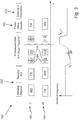
- Fig. 1A shows schematically a wireless network 100.
- the wireless network 100 comprises for the purposes of the present disclosure an initiator node "I" 102 and a responder node “R" 104, separated by a distance d 106, which is to be determined by wireless ranging involving transmissions indicated by arrows.
- Fig. 1B shows a block diagram of a wireless network node, which may be the initiator node 102 or the responder node 104.
- the wireless network node may for example be a Bluetooth low-energy (BLE) device or a IEEE 802.15.4, device, such as a Zigbee device.
- BLE Bluetooth low-energy
- IEEE 802.15.4 IEEE 802.15.4
- a processor 105 which may be a microcontroller or CPU, controls the node 102, 104 by executing software 108.
- the processor 105 controls a radio front end (FE) 103 comprising an analog-to-digital converter (ADC) 110 and a phased-lock loop (PLL) 112 for generating a local oscillator signal (LO) used for transmitting a carrier signal or as a reference when performing a phase measurement when receiving a carrier signal.
- the radio front end 103 is connected to an antenna 114 for receiving or transmitting signals.
- a clock reference 116 here in the form of a crystal, provides a reference for both the processor 105 and the radio front end 103, i.e., the same crystal to derive the RF frequencies and generate the baseband clock driving the digital circuitry.
- any relative offset ⁇ in the frequency of the clock reference 116 will affect both the timing of transmissions and measurements, as controlled by the processor 105, and of the frequencies of transmitted carrier signals and of the reference used for phase measurements, both as generated by the LO controlled by the PLL 112, in turn controlled by the clock reference 116.
- Fig. 2 is a flowchart of a method example 200 of wireless ranging which may be implemented in the wireless network 100 (cf. Fig. 1 ).
- a frequency index i may be set to zero.
- the initiator node 102 may transmit a ranging request and the responder node may receive the ranging request and reply by transmitting a ranging acknowledgement. Further, a time synchronization may be performed between the clock of the initiator node 102 and the clock of the responder node 104.
- a measurement procedure 204-210 is performed, resulting in a two-way phase measurement between the initiator node 102 and the responder node 104, as will be detailed in the following.
- a two-way phase measurement i . e ., a measurement of the round-trip phase advance between a first node and a second node, such as the initiator node 102 and the responder node 104, may be performed based on a combination of a phase measurement performed at the second node with the first node transmitting and a phase measurement at the first node with the second node transmitting.
- phase measurement at the second node made with respect to the second node's LO which is also used for generating the carrier signal transmitted by the second node
- phase measurement done at the first node made with respect to the first node's LO which is used for generating the carrier signal transmitted by the first node
- the initiator node 102 transmits on frequency f i an initiator carrier signal, which received by the responder node 104.
- the responder node 104 performs a phase measurement of the initiator carrier signal.
- the responder node measures the phase of the initiator carrier signal with respect to the local oscillator (LO) of the responder node.
- LO local oscillator
- the responder node 104 transmits on frequency f i a responder carrier signal, which is received by the initiator node 102.
- the initiator node 102 performs a phase measurement of the responder carrier signal.
- the initiator node 102 and the responder node 104 may switch to the next frequency f i+ 1 and repeat the measurement procedure 204, 206.
- the measurement procedure is repeated several times at different frequencies.
- the responder node 104 may transmit its phase measurement results for each frequency f i . This transmission is received by the initiator node 102.
- a wireless ranging device in the form of a calculating node, which may be the initiator node 102, may calculate the distance d between the initiator node 102 and the responder node 104 based on the gathered measurement results, which involve the two-way phase for the plurality of frequencies f i .
- the calculating node may be separate and distinct from the initiator node 102. Used as input to the calculation are the phase measurement results, i.e., the two-way phase measurements for the plurality of nominal frequencies and a clock reference offset correction of the initiator node and of the responder node, as will be detailed further below.
- Fig. 3 is a timing diagram of transmissions by the responder node "R” 104 and the initiator node “I” 102 during the method example 200 (cf. Fig. 2 ). Transmissions by each respective node are marked “TX” and reception by "RX”.
- the nominal frequency of transmission starts at a frequency f 0 increases linearly with a frequency step ⁇ f , ending at a frequency fKf-1.
- At 212 is the transmission by the responder node 104 of the measurement results, received by the initiator node 102.
- Fig. 4A is a detailed timing diagram of transmissions with nominal frequencies and phase measurement times, showing a sequence of transmissions and phase measurements, wherein transmissions by the initiator node 102 are shown with dashed lines and transmissions by the responder node 104 are shown with solid lines. Similarly, the timings of phase measurements performed by the initiator node 102 are indicated with dashed arrows and the timing of measurements performed by the responder node 104 are indicated by solid arrows.
- the phase measurement 206 by the initiator node 102 of the carrier signal transmitted by the responder node 104 is separated from the phase measurement 204 by the responder node 104 of the carrier signal transmitted by the initiator node 102 by a time interval T 0 .
- the respective phase measurements 206 by the initiator node 102 of the carrier signals transmitted by the responder node 104 and the respective phase measurements 204 by the responder node 104 of the carrier signals transmitted by the responder node 104 are separated by a time interval T f .
- Fig. 4B is a detailed timing diagram of transmissions with example actual frequencies and phase measurement times. It illustrates, in an exaggerated manner, how, due to a relative clock reference offset ⁇ r of the responder node 104 clock reference 116 and a relative clock reference offset ⁇ i of the initiator node clock reference 116, the actual frequencies of the carrier signals transmitted by the initiator node 102 and the responder node 104 and the time intervals T 0 and T f deviate from their nominal values, as can be seen by the solid lines - the vertical position of which corresponding to frequencies transmitted by the initiator node 102 - not perfectly lining up with the dashed lines - corresponding to frequencies transmitted by the responder node 104 - and by the timing of the phase measurements - represented by the vertical arrows - not perfectly lining up with the nominal time intervals T 0 and T f - as represented by brackets - and also moving in relation to successive transmissions.
- Fig. 5A is a block diagram illustrating calculating, at 214 (cf. Figs 2 and 3 ), and possibly implemented in the software 108 of the initiator node 102, the distance d between the initiator node 102 and the responder node 104 according to a first approach, wherein, based on the two-way phase measurements, represented by a vector ⁇ 2W , a preliminary distance d prel is calculated by a ranging engine 602 using methods known per se. Subtracted from that preliminary distance d prel is a clock reference offset correction e r calculated by a bias calculator 604, having as input the relative clock reference offset difference ⁇ r - ⁇ i and a timing and frequency plan of the measurement procedure.
- T 0 is a nominal time difference between, for a given nominal frequency of the plurality of nominal frequencies, the phase measurement at the responder node and the phase measurement at the initiator node (cf. Fig 4A ), ⁇ r is a relative clock reference offset of the responder node clock reference, ⁇ i is a relative clock reference offset of the initiator node clock reference, f c is a nominal starting frequency of the plurality of nominal frequencies, ⁇ f is the nominal frequency step in the plurality of nominal frequencies (cf. Fig 4A ), K f is the number of frequencies in the plurality of nominal frequencies, F is an optional pre-programmed nominal frequency offset, and c 0 is a signal propagation speed.
- clock reference offset correction e r is based on the relative clock reference offset difference ⁇ r - ⁇ i between the relative clock reference offset ⁇ i of the initiator node clock reference and the relative clock offset ⁇ r of the responder node clock reference.
- the calculating of the distance comprises calculating a preliminary distance between the initiator node and the responder node based on the plurality of nominal frequencies; and calculating a corrected distance between the initiator node and the responder node based on the nominal distance and the clock reference offset correction.
- Fig. 5B is a block diagram illustrating calculating, at 214 (cf. Figs 2 and 3 ), and possibly implemented in the software 108 of the initiator node 102, the distance d between the initiator node 102 and the responder node 104 according to a second approach, wherein, pre-distortions represented by a vector ⁇ err is calculated at 606, having as input the relative clock reference offset difference ⁇ r - ⁇ i and a timing and frequency plan of the measurement procedure.
- the pre-distortions ⁇ err are subtracted from the two-way phase measurements ⁇ 2W and the distance d is calculated by a ranging engine 602 using methods known per se.
- the calculating of the distance comprises calculating a pre-distortion for the two-way phase measurements based on the clock reference offset correction; forming a pre-distorted set of two-way phase measurements by applying the pre-distortion to the two-way phase measurements; calculating the distance between the initiator node and the responder node based on the pre-distorted set of two-way phase measurements.
- Fig. 5C is a block diagram illustrating calculating, at 214 (cf. Figs 2 and 3 ), and possibly implemented in the software 108 of the initiator node 102, the distance d between the initiator node 102 and the responder node 104 according to a third approach, wherein in addition to the second approach, the two-way phase measurements ⁇ 2W , as modified by the pre-distortions ⁇ err , are subjected to a frequency reordering 608, having as input the frequency plan, before computation by the ranging engine 602. This allows for more flexibility in the frequency plan and/or time plan, e.g., when using frequency hopping as used in most narrowband radio standards like BLE and 802.15.4 .
- T o is here treated as a constant, however, the concept is easily generalized for other cases, such as group ranging.
- f k i and f k r are the actual frequencies generated by respectively the initiator node 102 and the responder node 104
- T k i , T k r represent the actual time at which the phase is measured at the initiator node 102 and the responder node 104, respectively.
- Other symbols are defined as above.
- the distance d can then be estimated by computing the phase-difference of the two-way phase measurements for consecutive frequencies.
- the actual frequencies and time-offset will scale in the presence of clock reference offsets.
- the variable F which denotes any programmed frequency to model a software-controlled frequency offset.
- ⁇ o tends to be much larger than ⁇ f .
- F 0 kHz and a crystal-offset of at most +-20 ppm
- ⁇ o is at least a factor 20 larger than ⁇ f .
- the relative clock reference offset difference ⁇ r - ⁇ i may be obtained by one of the initiator node 102 or the responder node 104 performing a carrier frequency offset, CFO, measurement on a carrier signal transmitted by the other of the initiator node 102 and the responder node 104 using methods known per se. Thereby, for example, a dedicated carrier signal may be sent, of which both the initiator and reflector know the targeted frequency ( F t ). Assuming the initiator node 102 sends the dedicated carrier signal, the responder node 104 can measure the so-called carrier frequency offset (CFO).
- This designated carrier signal for CFO measurement can be appended placed at different places in measurement procedure 200 (conf. Figs 2 , 4 ). It could be derived from the ranging request packet or the ranging request acknowledgement, which are exchanged at 202 between initiator and reflector before the phase-measurements 204, 206 to exchange upcoming ranging parameters. Alternatively, a dedicated carrier signal could be placed between the ranging acknowledgement and the first carrier signal exchange of the measurement procedure 200. It could even be placed in the middle or the end of the measurement procedure 200.
- the CFO can be measured by either the initiator node 102 and/or the responder node 104.
- the relative clock reference offset difference can be communicated to the wireless node, where the distance estimate is computed 214, typically the initiator node 102.
- the relative clock reference offset difference ⁇ r - ⁇ i may be obtained by one of the initiator node 102 or the responder node 104 performing two or more time measurements on specific events within a single message or multiple messages transmitted by the other of the initiator node 102 and the responder node 104, e.g., time of arrival of the synch frame delimiters or symbol timing, where the time offset difference(s), TOD, between these time measurements compared to the expected time offset difference(s) allows for an estimation of the relative reference offset difference.
Landscapes
- Engineering & Computer Science (AREA)
- Radar, Positioning & Navigation (AREA)
- Remote Sensing (AREA)
- Physics & Mathematics (AREA)
- General Physics & Mathematics (AREA)
- Computer Networks & Wireless Communication (AREA)
- Radar Systems Or Details Thereof (AREA)
Priority Applications (2)
| Application Number | Priority Date | Filing Date | Title |
|---|---|---|---|
| EP19168443.0A EP3722831A1 (de) | 2019-04-10 | 2019-04-10 | Verfahren zur drahtlosen entfernungsmessung |
| US16/845,352 US11686807B2 (en) | 2019-04-10 | 2020-04-10 | Method of wireless ranging |
Applications Claiming Priority (1)
| Application Number | Priority Date | Filing Date | Title |
|---|---|---|---|
| EP19168443.0A EP3722831A1 (de) | 2019-04-10 | 2019-04-10 | Verfahren zur drahtlosen entfernungsmessung |
Publications (1)
| Publication Number | Publication Date |
|---|---|
| EP3722831A1 true EP3722831A1 (de) | 2020-10-14 |
Family
ID=66105071
Family Applications (1)
| Application Number | Title | Priority Date | Filing Date |
|---|---|---|---|
| EP19168443.0A Pending EP3722831A1 (de) | 2019-04-10 | 2019-04-10 | Verfahren zur drahtlosen entfernungsmessung |
Country Status (2)
| Country | Link |
|---|---|
| US (1) | US11686807B2 (de) |
| EP (1) | EP3722831A1 (de) |
Cited By (2)
| Publication number | Priority date | Publication date | Assignee | Title |
|---|---|---|---|---|
| CN117156530A (zh) * | 2023-08-31 | 2023-12-01 | 青岛柯锐思德电子科技有限公司 | 一种基于uwb的主动功率控制方法 |
| EP4462895A1 (de) * | 2023-05-11 | 2024-11-13 | Stichting IMEC Nederland | Verfahren und system zur schätzung des relativen zeitversatzes und des relativen taktversatzes |
Families Citing this family (5)
| Publication number | Priority date | Publication date | Assignee | Title |
|---|---|---|---|---|
| US20240085550A1 (en) * | 2021-01-18 | 2024-03-14 | Sony Semiconductor Solutions Corporation | Communication apparatus, communication system, and communication method |
| US11621738B1 (en) * | 2021-09-30 | 2023-04-04 | Shenzhen GOODIX Technology Co., Ltd. | Bidirectional phase-based distance estimation with crystal offset |
| US11522574B1 (en) * | 2021-09-30 | 2022-12-06 | Shenzhen GOODIX Technology Co., Ltd. | Phase based distance estimation with carrier frequency offset |
| US20240310510A1 (en) * | 2023-03-13 | 2024-09-19 | Qorvo Us, Inc. | Method of time-of-flight ranging between wireless devices |
| US12323153B2 (en) * | 2023-06-16 | 2025-06-03 | Cypress Semiconductor Corporation | Wireless per-frame-based local oscillator trimming for uplink multi-user transmission |
Citations (4)
| Publication number | Priority date | Publication date | Assignee | Title |
|---|---|---|---|---|
| US5220332A (en) * | 1992-05-04 | 1993-06-15 | Cyberdynamics, Inc. | Ranging by sequential tone transmission |
| US6744398B1 (en) | 2002-04-19 | 2004-06-01 | Derek J. Pyner | Distancing and positioning systems and methods |
| EP2196823A1 (de) | 2008-12-12 | 2010-06-16 | Lambda: 4 Entwicklungen GmbH | Verfahren zur Bestimmung der Entfernung zwischen zwei Objekten |
| EP3564707A1 (de) | 2018-05-04 | 2019-11-06 | Lambda: 4 Entwicklungen GmbH | Verfahren und system zur hochauflösenden entfernungs- und geschwindigkeitsmessung |
Family Cites Families (3)
| Publication number | Priority date | Publication date | Assignee | Title |
|---|---|---|---|---|
| DE102009060593A1 (de) * | 2008-12-30 | 2010-07-08 | Atmel Automotive Gmbh | System, Verfahren und Schaltung zur Entfernungsmessung zwischen zwei Knoten eines Funknetzes |
| FR3044100B1 (fr) * | 2015-10-19 | 2018-01-05 | Valeo Comfort And Driving Assistance | Procede d'estimation d'une distance et unite electronique pour vehicule |
| EP3700158A1 (de) * | 2019-02-19 | 2020-08-26 | Stichting IMEC Nederland | Sichere entfernungsbestimmung |
-
2019
- 2019-04-10 EP EP19168443.0A patent/EP3722831A1/de active Pending
-
2020
- 2020-04-10 US US16/845,352 patent/US11686807B2/en active Active
Patent Citations (4)
| Publication number | Priority date | Publication date | Assignee | Title |
|---|---|---|---|---|
| US5220332A (en) * | 1992-05-04 | 1993-06-15 | Cyberdynamics, Inc. | Ranging by sequential tone transmission |
| US6744398B1 (en) | 2002-04-19 | 2004-06-01 | Derek J. Pyner | Distancing and positioning systems and methods |
| EP2196823A1 (de) | 2008-12-12 | 2010-06-16 | Lambda: 4 Entwicklungen GmbH | Verfahren zur Bestimmung der Entfernung zwischen zwei Objekten |
| EP3564707A1 (de) | 2018-05-04 | 2019-11-06 | Lambda: 4 Entwicklungen GmbH | Verfahren und system zur hochauflösenden entfernungs- und geschwindigkeitsmessung |
Non-Patent Citations (2)
| Title |
|---|
| W. KLUGE; D. EGGERT: "Ranging with IEEE 802.15.4 narrowband PHY", IEEE P802.15 WORKING GROUP FOR WIRELESS PERSONAL AREA NETWORKS (WPANS, September 2009 (2009-09-01), Retrieved from the Internet <URL:https://mentor.ieee.org/802.15/dcn/09/15-09-0613-01-004franging-with-ieee-802-15-4-narrow-band-phy.ppt> |
| YI JIANG ET AL: "An Asymmetric Double Sided Two-Way Ranging for Crystal Offset", SIGNALS, SYSTEMS AND ELECTRONICS, 2007. ISSSE '07. INTERNATIONAL SYMPOSIUM ON, IEEE, PI, 1 July 2007 (2007-07-01), pages 525 - 528, XP031129329, ISBN: 978-1-4244-1448-2 * |
Cited By (3)
| Publication number | Priority date | Publication date | Assignee | Title |
|---|---|---|---|---|
| EP4462895A1 (de) * | 2023-05-11 | 2024-11-13 | Stichting IMEC Nederland | Verfahren und system zur schätzung des relativen zeitversatzes und des relativen taktversatzes |
| CN117156530A (zh) * | 2023-08-31 | 2023-12-01 | 青岛柯锐思德电子科技有限公司 | 一种基于uwb的主动功率控制方法 |
| CN117156530B (zh) * | 2023-08-31 | 2024-04-05 | 青岛柯锐思德电子科技有限公司 | 一种基于uwb的主动功率控制方法 |
Also Published As
| Publication number | Publication date |
|---|---|
| US20200326403A1 (en) | 2020-10-15 |
| US11686807B2 (en) | 2023-06-27 |
Similar Documents
| Publication | Publication Date | Title |
|---|---|---|
| US11686807B2 (en) | Method of wireless ranging | |
| US8965301B2 (en) | Distance measurement between two nodes of a radio network | |
| US10416301B2 (en) | Distance measurement between two nodes of a radio network | |
| US10466350B2 (en) | Transmitter-receiver circuit and method for distance measurement between a first node and a second node of a radio network | |
| US10928495B2 (en) | Method for distance determination | |
| JP5117507B2 (ja) | 無線通信システム、基地局間同期方法および基地局 | |
| US11774576B2 (en) | Phase-based ranging | |
| US8855485B2 (en) | Frequency offset estimating method and frequency offset estimating apparatus | |
| JP6092785B2 (ja) | レーダ装置 | |
| CN105264784B (zh) | 同步方法、接收端及发送端 | |
| US20180248738A1 (en) | Apparatus for a radio device | |
| US11310085B2 (en) | LoRa advanced receiver | |
| US12405347B2 (en) | Method for determining distance between a plurality of objects | |
| AU2012277420A1 (en) | Estimation of frequency offset between a base station and mobile terminal | |
| JP2022053144A (ja) | 位相補正装置及び測距装置 | |
| EP4618467A1 (de) | Verfahren und vorrichtung zur zeitsynchronisierung | |
| US11067663B2 (en) | Apparatus and method of flight measurement | |
| EP4012933B1 (de) | Fortschrittlicher lora-empfänger | |
| US20240377527A1 (en) | Method and a system for estimating relative time offset and relative clock skew | |
| CN103220243A (zh) | 一种确定频偏估计值的方法和设备 | |
| US20240284374A1 (en) | Method and apparatus for v2x positioning | |
| CN115877337A (zh) | 具有相位噪声校正的雷达 | |
| EP3672116B1 (de) | Phasenbasierte gruppeentfernungsmessung | |
| CN116567796B (zh) | 无线多节点时频同步方法、装置、电子设备及存储介质 | |
| US20260025163A1 (en) | Adaptive scheduling for indoor navigation using uwb anchor infrastructure |
Legal Events
| Date | Code | Title | Description |
|---|---|---|---|
| PUAI | Public reference made under article 153(3) epc to a published international application that has entered the european phase |
Free format text: ORIGINAL CODE: 0009012 |
|
| STAA | Information on the status of an ep patent application or granted ep patent |
Free format text: STATUS: THE APPLICATION HAS BEEN PUBLISHED |
|
| AK | Designated contracting states |
Kind code of ref document: A1 Designated state(s): AL AT BE BG CH CY CZ DE DK EE ES FI FR GB GR HR HU IE IS IT LI LT LU LV MC MK MT NL NO PL PT RO RS SE SI SK SM TR |
|
| AX | Request for extension of the european patent |
Extension state: BA ME |
|
| STAA | Information on the status of an ep patent application or granted ep patent |
Free format text: STATUS: REQUEST FOR EXAMINATION WAS MADE |
|
| 17P | Request for examination filed |
Effective date: 20210412 |
|
| RBV | Designated contracting states (corrected) |
Designated state(s): AL AT BE BG CH CY CZ DE DK EE ES FI FR GB GR HR HU IE IS IT LI LT LU LV MC MK MT NL NO PL PT RO RS SE SI SK SM TR |
|
| TPAC | Observations filed by third parties |
Free format text: ORIGINAL CODE: EPIDOSNTIPA |
|
| STAA | Information on the status of an ep patent application or granted ep patent |
Free format text: STATUS: EXAMINATION IS IN PROGRESS |
|
| 17Q | First examination report despatched |
Effective date: 20230209 |