EP3722904B1 - Bewegliches fahrzeug, steuerverfahren und steuerprogramm - Google Patents
Bewegliches fahrzeug, steuerverfahren und steuerprogramm Download PDFInfo
- Publication number
- EP3722904B1 EP3722904B1 EP18885277.6A EP18885277A EP3722904B1 EP 3722904 B1 EP3722904 B1 EP 3722904B1 EP 18885277 A EP18885277 A EP 18885277A EP 3722904 B1 EP3722904 B1 EP 3722904B1
- Authority
- EP
- European Patent Office
- Prior art keywords
- self
- location
- unit
- time
- information
- Prior art date
- Legal status (The legal status is an assumption and is not a legal conclusion. Google has not performed a legal analysis and makes no representation as to the accuracy of the status listed.)
- Not-in-force
Links
Images







Classifications
-
- G—PHYSICS
- G05—CONTROLLING; REGULATING
- G05D—SYSTEMS FOR CONTROLLING OR REGULATING NON-ELECTRIC VARIABLES
- G05D1/00—Control of position, course, altitude or attitude of land, water, air or space vehicles, e.g. using automatic pilots
- G05D1/02—Control of position or course in two dimensions
- G05D1/021—Control of position or course in two dimensions specially adapted to land vehicles
- G05D1/0212—Control of position or course in two dimensions specially adapted to land vehicles with means for defining a desired trajectory
- G05D1/0221—Control of position or course in two dimensions specially adapted to land vehicles with means for defining a desired trajectory involving a learning process
-
- G—PHYSICS
- G05—CONTROLLING; REGULATING
- G05D—SYSTEMS FOR CONTROLLING OR REGULATING NON-ELECTRIC VARIABLES
- G05D1/00—Control of position, course, altitude or attitude of land, water, air or space vehicles, e.g. using automatic pilots
- G05D1/02—Control of position or course in two dimensions
- G05D1/021—Control of position or course in two dimensions specially adapted to land vehicles
- G05D1/0268—Control of position or course in two dimensions specially adapted to land vehicles using internal positioning means
- G05D1/027—Control of position or course in two dimensions specially adapted to land vehicles using internal positioning means comprising intertial navigation means, e.g. azimuth detector
-
- G—PHYSICS
- G05—CONTROLLING; REGULATING
- G05D—SYSTEMS FOR CONTROLLING OR REGULATING NON-ELECTRIC VARIABLES
- G05D1/00—Control of position, course, altitude or attitude of land, water, air or space vehicles, e.g. using automatic pilots
- G05D1/40—Control within particular dimensions
- G05D1/49—Control of attitude, i.e. control of roll, pitch or yaw
-
- G—PHYSICS
- G05—CONTROLLING; REGULATING
- G05D—SYSTEMS FOR CONTROLLING OR REGULATING NON-ELECTRIC VARIABLES
- G05D1/00—Control of position, course, altitude or attitude of land, water, air or space vehicles, e.g. using automatic pilots
- G05D1/02—Control of position or course in two dimensions
- G05D1/021—Control of position or course in two dimensions specially adapted to land vehicles
- G05D1/0231—Control of position or course in two dimensions specially adapted to land vehicles using optical position detecting means
- G05D1/0238—Control of position or course in two dimensions specially adapted to land vehicles using optical position detecting means using obstacle or wall sensors
-
- G—PHYSICS
- G05—CONTROLLING; REGULATING
- G05D—SYSTEMS FOR CONTROLLING OR REGULATING NON-ELECTRIC VARIABLES
- G05D1/00—Control of position, course, altitude or attitude of land, water, air or space vehicles, e.g. using automatic pilots
- G05D1/02—Control of position or course in two dimensions
- G05D1/021—Control of position or course in two dimensions specially adapted to land vehicles
- G05D1/0231—Control of position or course in two dimensions specially adapted to land vehicles using optical position detecting means
- G05D1/0246—Control of position or course in two dimensions specially adapted to land vehicles using optical position detecting means using a video camera in combination with image processing means
-
- G—PHYSICS
- G05—CONTROLLING; REGULATING
- G05D—SYSTEMS FOR CONTROLLING OR REGULATING NON-ELECTRIC VARIABLES
- G05D1/00—Control of position, course, altitude or attitude of land, water, air or space vehicles, e.g. using automatic pilots
- G05D1/02—Control of position or course in two dimensions
- G05D1/021—Control of position or course in two dimensions specially adapted to land vehicles
- G05D1/0268—Control of position or course in two dimensions specially adapted to land vehicles using internal positioning means
- G05D1/0272—Control of position or course in two dimensions specially adapted to land vehicles using internal positioning means comprising means for registering the travel distance, e.g. revolutions of wheels
-
- G—PHYSICS
- G05—CONTROLLING; REGULATING
- G05D—SYSTEMS FOR CONTROLLING OR REGULATING NON-ELECTRIC VARIABLES
- G05D1/00—Control of position, course, altitude or attitude of land, water, air or space vehicles, e.g. using automatic pilots
- G05D1/20—Control system inputs
- G05D1/24—Arrangements for determining position or orientation
- G05D1/242—Means based on the reflection of waves generated by the vehicle
-
- G—PHYSICS
- G05—CONTROLLING; REGULATING
- G05D—SYSTEMS FOR CONTROLLING OR REGULATING NON-ELECTRIC VARIABLES
- G05D1/00—Control of position, course, altitude or attitude of land, water, air or space vehicles, e.g. using automatic pilots
- G05D1/20—Control system inputs
- G05D1/24—Arrangements for determining position or orientation
- G05D1/243—Means capturing signals occurring naturally from the environment, e.g. ambient optical, acoustic, gravitational or magnetic signals
-
- G—PHYSICS
- G05—CONTROLLING; REGULATING
- G05D—SYSTEMS FOR CONTROLLING OR REGULATING NON-ELECTRIC VARIABLES
- G05D1/00—Control of position, course, altitude or attitude of land, water, air or space vehicles, e.g. using automatic pilots
- G05D1/20—Control system inputs
- G05D1/24—Arrangements for determining position or orientation
- G05D1/247—Arrangements for determining position or orientation using signals provided by artificial sources external to the vehicle, e.g. navigation beacons
-
- G—PHYSICS
- G05—CONTROLLING; REGULATING
- G05D—SYSTEMS FOR CONTROLLING OR REGULATING NON-ELECTRIC VARIABLES
- G05D1/00—Control of position, course, altitude or attitude of land, water, air or space vehicles, e.g. using automatic pilots
- G05D1/60—Intended control result
- G05D1/617—Safety or protection, e.g. defining protection zones around obstacles or avoiding hazards
- G05D1/622—Obstacle avoidance
-
- G—PHYSICS
- G05—CONTROLLING; REGULATING
- G05D—SYSTEMS FOR CONTROLLING OR REGULATING NON-ELECTRIC VARIABLES
- G05D1/00—Control of position, course, altitude or attitude of land, water, air or space vehicles, e.g. using automatic pilots
- G05D1/60—Intended control result
- G05D1/644—Optimisation of travel parameters, e.g. of energy consumption, journey time or distance
-
- G—PHYSICS
- G06—COMPUTING OR CALCULATING; COUNTING
- G06N—COMPUTING ARRANGEMENTS BASED ON SPECIFIC COMPUTATIONAL MODELS
- G06N3/00—Computing arrangements based on biological models
- G06N3/02—Neural networks
- G06N3/04—Architecture, e.g. interconnection topology
-
- G—PHYSICS
- G06—COMPUTING OR CALCULATING; COUNTING
- G06N—COMPUTING ARRANGEMENTS BASED ON SPECIFIC COMPUTATIONAL MODELS
- G06N3/00—Computing arrangements based on biological models
- G06N3/02—Neural networks
- G06N3/08—Learning methods
-
- G—PHYSICS
- G06—COMPUTING OR CALCULATING; COUNTING
- G06N—COMPUTING ARRANGEMENTS BASED ON SPECIFIC COMPUTATIONAL MODELS
- G06N3/00—Computing arrangements based on biological models
- G06N3/02—Neural networks
- G06N3/08—Learning methods
- G06N3/09—Supervised learning
-
- G—PHYSICS
- G05—CONTROLLING; REGULATING
- G05D—SYSTEMS FOR CONTROLLING OR REGULATING NON-ELECTRIC VARIABLES
- G05D2101/00—Details of software or hardware architectures used for the control of position
- G05D2101/10—Details of software or hardware architectures used for the control of position using artificial intelligence [AI] techniques
-
- G—PHYSICS
- G05—CONTROLLING; REGULATING
- G05D—SYSTEMS FOR CONTROLLING OR REGULATING NON-ELECTRIC VARIABLES
- G05D2109/00—Types of controlled vehicles
- G05D2109/10—Land vehicles
- G05D2109/12—Land vehicles with legs
Definitions
- the present disclosure relates to a control device and a control method, a program, and a mobile object, and particularly relates to a control device and a control method for generating an action plan by a computing machine to enable autonomous movement even when a self-location is unknown, a program, and a mobile object.
- Patent Document 2 proposes a technology for monitoring a fluctuation due to a difference between a control input amount related to traveling and an actual movement amount, and stopping traveling when the fluctuation deviates from a controllable range due to a disturbance and the self-location cannot be recognized.
- Patent Document 3 relates to a moving apparatus and an apparatus, method, and medium for compensating position based on a position recognition technology.
- the moving apparatus which provides a function for correcting a position includes a sensing unit obtaining multiple state information reflecting one or more abnormal movement states generated by movements of the moving apparatus; a state determination unit determining whether or not the abnormal movement state is generated by self-contained navigation, by referring to the obtained multiple state information; and a position information calculation unit calculating final position information of the moving apparatus, by correcting the multiple state information as the abnormal movement state occurs.
- Non-Patent Document 1 relates to a new localization method for mobile robot by data fusion of vision sensor data and motion sensor data.
- Non-Patent Document 1 TAE-JAE LEE ET AL, "A new localization method for mobile robot by data fusion of vision sensor data and motion sensor data", ROBOTICS AND BIOMIMETICS (ROBIO), 2012 IEEE INTERNATIONAL CONFERENCE ON, IEEE, (20121211), 11 December 2012, pages 723-728, XP03235286, doi:10.1109/ROBlO.2012.6491053, ISBN 978-1-4673-2125-9
- Patent Document 1 specifies that correction after the kidnap reflects a movement distance during the kidnap, and the self-location is not to be determined again. Therefore, there is a possibility that the self-location cannot be detected accurately.
- Patent Document 2 is limited to monitoring a fluctuation due to a difference between a control input amount and an actual movement amount, and there is a possibility that the self-location cannot be estimated again by using a plurality of sensors.
- the present disclosure has been made in view of such a situation, and it is particularly intended to enable estimation of the self-location again from a state where the self-location is unknown.
- a control device is a control device including: a self-position detection unit configured to detect a self-position on the basis of sensor information; a position change detection unit configured to detect a position change unpredictable in advance, on the basis of a detection result by the self-position detection unit; and a self-location estimation unit configured to estimate a self-location with a first estimation model on the basis of sensor information, and estimate a self-location with a second estimation model different from the first estimation model in a case where the position change unpredictable in advance is detected by the position change detection unit.
- the self-location estimation unit may include: a time-series information accumulation unit that accumulates the sensor information as time-series information; and a time-series information self-location estimation unit configured to use time-series information accumulated in the time-series information accumulation unit to estimate the self-location, and output an estimation result as a time-series information self-location.
- the time-series information accumulation unit the time-series information of a past time that has been accumulated may be reset in a case where the position change unpredictable in advance is detected.
- the time-series information self-location estimation unit may be configured to: use time-series information accumulated in the time-series information accumulation unit to estimate the self-location, as the first estimation model; and use time-series information accumulated in the time-series information accumulation unit after time-series information of a past time that has been accumulated in the time-series information accumulation unit is reset, to estimate the self-location, as the second estimation model.
- the past time-series information accumulated in the time-series information accumulation unit can be deleted by the reset, in an order from time-series information accumulated longer than a predetermined time.
- the time-series information self-location estimation unit may be configured to: reduce a weight of the self-location estimated with the time-series information as the time-series information has been accumulated for a longer time in the time-series information accumulation unit after the reset is performed on past time-series information accumulated in the time-series information accumulation unit, to estimate the time-series information self-location.
- the self-location estimation unit may include a time-series information self-location estimation unit configured to estimate a time-series information self-location by using a Kalman filter that repeats a step of updating an observation value of a prior probability density distribution with time-series information that is latest.
- the time-series information self-location estimation unit may be configured to: estimate the time-series information self-location by using a Kalman filter that repeats a step of updating an observation value of a prior probability density distribution with time-series information that is latest, as the first estimation model, and estimate the time-series information self-location by using the Kalman filter after maximizing a weight of the time-series information that is latest, as the second estimation model, in a case where the position change unpredictable in advance is detected.
- the self-location estimation unit may include: a time-series information accumulation unit that accumulates as time-series information sensed with the sensor information; a time-series information self-location estimation unit configured to use time-series information accumulated in the time-series information accumulation unit to estimate the self-location, and output an estimation result as a time-series information self-location; and a current information self-location estimation unit configured to estimate the self-location on the basis of current information that is current information sensed with the sensor information, and output as a current information self-location.
- the self-location estimation unit may be configured to adopt the time-series information self-location as a self-location estimation result in a case where the position change unpredictable in advance is not detected, and adopt the current information self-location as a self-location estimation result in a case where the position change unpredictable in advance is detected.
- the self-location estimation unit may be configured to: cause transition of an operation mode to at least a first mode, a second mode, and a third mode in accordance with a detection result of the position change detection unit; set the operation mode to the first mode at a start of an operation and estimate the self-location with the first estimation model; cause, in the first mode, transition of the operation mode to the second mode and notify that the position change unpredictable in advance has been detected in a case where the position change unpredictable in advance is detected by the position change detection unit; cause, in the second mode, transition of the operation mode to the third mode after a predetermined time has elapsed, and estimate the self-location with the second estimation model; and cause, in the third mode, transition of the operation mode to the first mode after a predetermined time has elapsed.
- the self-location estimation unit may include: a time-series information accumulation unit that accumulates the sensor information as time-series information; a time-series information self-location estimation unit configured to use time-series information accumulated in the time-series information accumulation unit to estimate the self-location, and output an estimation result as a time-series information self-location; and a current information self-location estimation unit configured to estimate the self-location on the basis of current information that is current information sensed with the sensor information, and output as a current information self-location.
- the self-location estimation unit may be configured to: adopt, in the first mode, as a self-location estimation result, the time-series information self-location estimated by the time-series information self-location estimation unit with use of time-series information accumulated in the time-series information accumulation unit, as the first estimation model; and adopt, in the third mode, as a self-location estimation result, the current information self-location estimated by the current information self-location estimation unit with use of the current information, as the second estimation model.
- the position change unpredictable in advance may be a change to a state where a change in the self-location and a position loses continuity.
- the first mode may be a normal mode
- the second mode may be an uncertain self-location mode
- the third mode may be a current information self-location estimation mode.
- the self-location estimation unit may be configured to cause transition of the operation mode to the uncertain self-location mode, which is the second mode, when the position change unpredictable in advance is detected, in a case where the operation mode is the current information self-location estimation mode, which is the third mode.
- the state where a change in the self-location and a position loses continuity may include a kidnap state, a slip state of a sole contact surface and a wheel, getting on and off of a non-fixed object, and a sensor abnormal state.
- the position change unpredictable in advance may be a change to an accident occurrence state.
- the first mode may be the normal mode
- the second mode may be a right-after-accident mode
- the third mode may be a control recovery mode.
- the accident occurrence state may include a collision with a person, an object, and another machine or vehicle, a puncture, a missing part, and a falling state of a part and a cargo.
- the time-series information may be three-dimensional point cloud information detected by LIDAR, and may be location information, a position, a velocity, an acceleration, and an angular velocity detected by a wheel encoder.
- the time-series information self-location estimation unit is configured to estimate the self-location by using a Kalman filter or a particle filter on the basis of the time-series information, and output an estimation result as a time-series information self-location.
- the current information may be a parallax image captured by a stereo camera.
- the current information self-location estimation unit is configured to generate a depth image from the parallax image, extract an image feature amount from the depth image, estimate a self-location on the basis of the image feature amount, and output an estimation result as a current information self-location.
- the sensor information used when the self-position detection unit detects the self-position may include a vertical acceleration.
- the self-position detection unit may include: a frequency component extraction unit configured to extract a frequency component of a change in the vertical acceleration; a feature amount extraction unit configured to extract a feature amount from a frequency component extracted by the frequency component extraction unit; and a position detection unit configured to detect the self-position on the basis of the feature amount.
- the position detection unit may be configured to detect the position by searching for a corresponding position from the database on the basis of the feature amount.
- the database it is possible to register the position and the feature amount of the frequency component in association with each other by learning using a neural network, on the basis of sensor information for the known position.
- a control method is a control method including: a self-position detection process of detecting a self-position on the basis of sensor information; a position change detection process of detecting a position change unpredictable in advance on the basis of a detection result by the self-position detection process; and a self-location estimation process of estimating a self-location with a first estimation model on the basis of sensor information, and estimating a self-location with a second estimation model different from the first estimation model in a case where the position change unpredictable in advance is detected by the position change detection process.
- a program according to an example of the present disclosure is a program for causing a computer to function as: a self-position detection unit configured to detect a self-position on the basis of sensor information; a position change detection unit configured to detect a position change unpredictable in advance, on the basis of a detection result by the self-position detection unit; and a self-location estimation unit configured to estimate a self-location with a first estimation model on the basis of sensor information, and estimate a self-location with a second estimation model different from the first estimation model in a case where the position change unpredictable in advance is detected by the position change detection unit.
- a mobile object is a mobile object including: a self-position detection unit configured to detect a self-position on the basis of sensor information; a position change detection unit configured to detect a position change unpredictable in advance, on the basis of a detection result by the self-position detection unit; a self-location estimation unit configured to estimate a self-location with a first estimation model on the basis of sensor information, and estimate a self-location with a second estimation model different from the first estimation model in a case where the position change unpredictable in advance is detected by the position change detection unit; an action plan generation unit configured to generate an action plan on the basis of a peripheral situation of a self-location estimated by the self-location estimation unit; and a control unit configured to control an operation of the mobile object on the basis of an action plan determined by the action plan generation unit.
- a self-position is detected on the basis of sensor information, a position change unpredictable in advance is detected on the basis of a detection result, a self-location is estimated with the first estimation model on the basis of sensor information, and the self-location is estimated with the second estimation model different from the first estimation model in a case where the position change unpredictable in advance is detected.
- a self-location can be estimated again even in a state where the self-location is unknown.
- a mobile object of the present disclosure is a mobile object that newly estimates a self-location again even after the self-location is lost due to an external force, when repeating new self-location estimation by using past self-location estimation results that have been continuously estimated.
- Fig. 1 illustrates a configuration example that is an outline of a mobile object 11 according to the present disclosure.
- the mobile object 11 is, for example, a robot or the like, and includes a sensor group 21, an autonomous movement control unit 22, and an actuator group 23.
- the sensor group 21 includes sensors 21a-1 to 21a-n that detect various kinds of information necessary for recognizing a situation inside the mobile object 11 and in surroundings of the mobile object 11, and outputs a detection result to the autonomous movement control unit 22. Furthermore, in a case where it is not necessary to particularly distinguish, the sensors 21a-1 to 21a-n are simply referred to as a sensor 21a, and other configurations are also similarly referred to.
- the self-location estimation unit 132 accumulates time-series information supplied in a time series in the database on the basis of a detection result supplied from the sensor group 112, estimates a self-location on the basis of the accumulated time-series information, and outputs as a time-series information self-location. Furthermore, the self-location estimation unit 132 estimates a self-location on the basis of the current detection result supplied from the sensor group 112, and outputs as a current information self-location. Then, the self-location estimation unit 132 outputs as the self-location estimation result by integrating or switching the time-series information self-location and the current information self-location.
- the situation recognition unit 152 performs situation recognition processing related to the mobile object, on the basis of data or a signal from each unit of the mobile object control system 100 such as the self-location estimation unit 132, the mobile-object external information detection unit 141, the mobile-object internal information detection unit 142, the mobile-object state detection unit 143, and the map analysis unit 151.
- the situation recognition unit 152 performs recognition processing on a situation of the mobile object, a situation around the mobile object, a situation of a driver of the mobile object, and the like.
- the situation recognition unit 152 generates a local map (hereinafter, referred to as a situation recognition map) used for recognizing a situation around the mobile object, as necessary.
- the situation recognition map is, for example, an occupancy grid map, a lane map, or a point cloud map.
- the situation prediction unit 153 supplies data indicating a result of the prediction processing, together with data from the situation recognition unit 152, to the route planning unit 161, the action planning unit 162, and the operation planning unit 163 of the planning unit 134, and the like.
- the sensor group 112 includes LIDAR 201, a wheel encoder 202, a stereo camera 203, and an internal sensor 204. Naturally, other sensors may be used in a case of a four-legged walking robot, a car, or the like.
- the wheel encoder 202 detects location information (X, Y, Z), a position (quaternion), a velocity (dx, dy, dz), an acceleration (ax, ay, az), and an angular velocity (wx, wy, wz) of the mobile object 11, and outputs as time-series information to the time-series information self-location estimation unit 221 via the detection unit 131.
- the self-location estimation unit 132 includes the time-series information self-location estimation unit 221, a time-series information DB 222, the current information self-location estimation unit 223, a position image feature amount DB 224, a self-location estimation result switching unit 225, a self-position detection unit 226, a feature amount position DB 227, and a position change detection unit 228.
- the time-series information self-location estimation unit 221 stores, in the time-series information DB 222, time-series information such as three-dimensional point cloud data supplied by the LIDAR 201 and the wheel encoder 202 and expressing a self-location and a location of a surrounding obstacle. Furthermore, the time-series information self-location estimation unit 221 reads time-series information of the past to the present as necessary from the time-series information DB 222, estimates the self-location on the basis of the read time-series information from the past to the present, and supplies to the self-location estimation result switching unit 225.
- SLAM simultaneous localisation and mapping
- the self-position detection unit 226 detects the self-position of the mobile object 11 on the basis of a detection result supplied from the internal sensor 204, and outputs to the position change detection unit 228.
- the self-position detection unit 226 includes a frequency component extraction unit 271, a feature amount extraction unit 272, and a position detection unit 273.
- the feature amount extraction unit 272 extracts a feature amount from the frequency component of the vibration of the mobile object 11 supplied from the frequency component extraction unit 271, and outputs to the position detection unit 273.
- the position detection unit 273 accesses the feature amount position DB 227 in which a feature amount and a position are registered in association with each other in advance by learning, extracts a position registered in association on the basis of the extracted feature amount, and outputs to the position change detection unit 228 as information on a current position of the mobile object 11.
- the information on the position detected by the position detection unit 273 on the basis of the feature amount includes at least three types of positions: a normal walking state, lifting, and a stationary state.
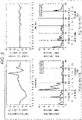
- a traveling state of the mobile object 11 and a so-called lifted state (kidnap state) in which the mobile object 11 is suddenly lifted can be identified, for example, on the basis of a vertical acceleration and a power spectrum that is a frequency analysis result thereof.
- a lower part in Fig. 5 is an acceleration in an x direction (x), a y direction (y), and a z (z) direction from the left, and is a power spectrum for each rotational speed in the x direction (rx), the y direction (ry), and the z direction (zy), in which a horizontal axis indicates a frequency (Hz: 10 Hz each), and a vertical axis indicates each power spectrum.
- the x and y directions are a horizontal coordinate system
- the z direction is a perpendicular (vertical) coordinate system.
- the upper part and the lower part of on the left in Fig. 5 both show a waveform in a lifted state (kidnap state), and the upper part and the lower part of on the right in Fig. 5 both show a waveform in a traveling state.
- the average is almost 1.0 or more in a range up to 2.5 Hz, and the average is almost 2.0 or less in a range of 5 Hz to 10 Hz.
- the average is almost 2.0 or more in a range up to 2.5 Hz and the average is 1.0 or less in a range of 5 Hz to 10 Hz.
- the power spectrum is 2.5 or more in the range up to 2.5 Hz in the z direction, becomes almost 1.0 or more on average in the range up to 2.5 Hz, and the becomes almost 2.0 or less on average in the range of 5 Hz to 10 Hz.
- the position detection method may be another method, for example, please refer to “Gesture Recognition using Gyroscopes and Accelerometers, by Takashi Itaguchi, Tsutomu Kanamori, Haruhiro Katayose, Kosuke Sato, and Seiji Inokuchi” and “Learning Activity Recognition Models with Physical Characteristics Data of Users, by Takuya Maekawa, Shinji Watanabe".
- the feature amount and the position are registered in association with each other in the feature amount position DB 227 in this manner. Therefore, the position detection unit 273 accesses the feature amount position DB 227 and detects a position registered in association with the feature amount obtained from the frequency analysis result.
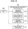
- a feature amount position DB generation unit 301 ( Fig. 6 ) that generates the feature amount position DB 227 will be described later in detail with reference to Fig. 6 .
- the position change detection unit 228 acquires position information outputted from the self-position detection unit 226, detects the presence or absence of a position change, and outputs a detection result to the self-location estimation result switching unit 225. More specifically, the position change detection unit 228 detects at least three types of position changes of the mobile object 11, that is, a normal walking state, lifting, and a stationary state, and outputs a detection result to the self-location estimation result switching unit 225.
- the self-location estimation result switching unit 225 switches or integrates the time-series information self-location supplied from the time-series information self-location estimation unit 221 and the current information self-location supplied from the current information self-location estimation unit 223, and outputs to the situation analysis unit 133 as a self-location estimation result.
- the self-location estimation result switching unit 225 includes a position change determination unit 251, determines whether or not it is notified that a position change has been detected from the position change detection unit 228, and resets and deletes all the time-series information stored in the time-series information DB 222 when it is notified that a position change has been detected.
- the feature amount position DB generation unit 301 learns a relationship with a feature amount extracted from a detection result for each position, and registers in the feature amount position DB 227.
- the feature amount position DB generation unit 301 includes a frequency component extraction unit 311, a feature amount extraction unit 312, and a feature amount position learning unit 313.
- the frequency component extraction unit 311 is a configuration corresponding to the frequency component extraction unit 271, and reads a detection result of the internal sensor 204 in which a past position is known, from the position DB 302. Then, the frequency component extraction unit 311 analyzes and extracts a frequency component of vibration, which is the read detection result, for example, by applying fast Fourier transform (FFT), and outputs to the feature amount extraction unit 312 together with the position information.
- FFT fast Fourier transform
- the feature amount extraction unit 312 is a configuration corresponding to the feature amount extraction unit 272, extracts a feature amount from the frequency component supplied from the frequency component extraction unit 311, and outputs to the feature amount position learning unit 313 together with the position information.
- the feature amount position learning unit 313 learns a relationship between a position known in advance and a corresponding feature amount, and associates and registers the relationship between the position and the feature amount obtained as a learning result in the feature amount position DB 227.
- step S11 the LIDAR 201 acquires a distance to an object around the mobile object 11 as three-dimensional point cloud data, and outputs as time-series information to the time-series information self-location estimation unit 221 of the self-location estimation unit 132, via the detection unit 131.
- step S12 the wheel encoder 202 detects location information, a position, a velocity, an acceleration, and an angular velocity of the mobile object 11, and outputs as time-series information to the time-series information self-location estimation unit 221 via the detection unit 131.
- step S13 the time-series information self-location estimation unit 221 acquires latest time-series information, and registers in the time-series information DB 222.
- step S14 the time-series information self-location estimation unit 221 estimates a self-location, for example, by SLAM from the latest time-series information and past time-series information registered in the time-series information DB 222, and outputs an estimation result to the self-location estimation result switching unit 225 as time-series information self-location information.
- step S15 the time-series information self-location estimation unit 221 determines whether or not termination of the process has been instructed, and the process returns to step S11 in a case of not termination.
- the time-series information detected by the LIDAR 201 and the wheel encoder 202 is sequentially detected, and sequentially accumulated in the time-series information DB 206. Further, on the basis of the time-series information accumulated in a time series from the past to the present accumulated in a time series, a time-series information self-location is estimated, and repeatedly outputted to the self-location estimation result switching unit 225.
- step S31 the stereo camera 203 captures a parallax image of surroundings of the mobile object 11, and outputs as current information to the current information self-location estimation unit 223 via the detection unit 131.
- step S32 the current information self-location estimation unit 223 generates a depth image (distance image) on the basis of a parallax image supplied from the stereo camera 203.
- step S33 the current information self-location estimation unit 223 extracts an image feature amount from the generated depth image.
- step S35 the current information self-location estimation unit 223 determines whether or not termination of the process has been instructed, and the process returns to step S31 in a case of not termination.
- step S35 in a case where termination of the process is instructed, the process is terminated.
- a parallax image is captured as current information by the stereo camera 203, a depth image is generated from the parallax image as the current information, an image feature amount of the generated depth image is extracted, and a current information self-location is estimated on the basis of the location information registered in association with the image feature amount and is repeatedly outputted to the self-location estimation result switching unit 225.
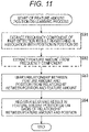
- step S51 the internal sensor 204 detects an acceleration, an angle, an angular velocity, a geomagnetic direction, and the like of the mobile object 11, and outputs to the self-position detection unit 226 of the self-location estimation unit 132 via the detection unit 131.
- step S52 the frequency component extraction unit 271 of the self-position detection unit 226 performs frequency analysis by applying FFT on detection results of the acceleration, the angle, the angular velocity, and the geomagnetic direction detected by the internal sensor 204, and outputs an analysis result to the feature amount extraction unit 272.
- step S53 the feature amount extraction unit 272 extracts a feature amount from the frequency analysis result, and outputs to the position detection unit 273.
- step S54 the position detection unit 273 accesses the feature amount position DB 227 as described with reference to Fig. 5 , searches for information on a corresponding position on the basis of the feature amount, detects a search result as a current position, and outputs to the position change detection unit 228.
- step S55 the position change detection unit 228 stores the new current position information supplied from the self-position detection unit 226, and gives a notification to the self-location estimation result switching unit 225.
- step S56 the position change detection unit 228 compares the new current position information supplied from the self-position detection unit 226 with position information stored immediately before, and determines whether or not a change has occurred in the position.
- step S56 In a case where it is considered in step S56 that the position immediately before is different from the current position and a change has occurred, the process proceeds to step S57.
- step S57 the position change detection unit 228 notifies the self-location estimation result switching unit 225 that the position has changed.
- step S57 In a case where no position change is detected in step S56, the processing in step S57 is skipped.
- step S58 the self-position detection unit 226 determines whether or not termination of the process has been instructed, and the process returns to step S51 in a case of not termination. In other words, until termination is instructed, the processing in steps S51 to S58 is repeated to detect the self-position, and to continuously detect the presence or absence of a change.
- step S58 in a case where termination of the process is instructed, the process is terminated.
- a position of the mobile object 11 is detected, and information on the detected position is notified to the self-location estimation result switching unit 225. Furthermore, information on the detected position is sequentially stored, and it is determined whether or not the position has changed by comparing the information on the detected current position with a position stored immediately before. In a case where a position change is detected, the self-location estimation result switching unit 225 is notified that the position change has been detected.
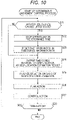
- step S71 the position change determination unit 251 of the self-location estimation result switching unit 225 determines whether or not it is notified that there has been detected a position change of changing to a position indicating a lifted state (kidnap state), which is detected by the position change detection process.
- step S71 In a case where the position change of changing to the position indicating a lifted state (kidnap state) is detected in step S71, the process proceeds to step S72.
- step S72 the self-location estimation result switching unit 225 outputs an instruction to the action control processing unit 123 to stop the mobile object 11 for a predetermined time. Accordingly, the action control processing unit 123 controls the actuator group 113 to stop the operation of the mobile object 11 for a predetermined time.
- step S73 after the predetermined time has elapsed and the stop of the operation has been canceled, the self-location estimation result switching unit 225 resets past time-series information registered in the time-series information DB 222.
- step S71 In a case where it is considered in step S71 that the position change has not been detected, the processing in steps S72 and S73 is skipped. In other words, in this case, the registered state of the past time-series information registered in the time-series information DB 222 is maintained without being reset. Furthermore, when the lifted state is detected, all the information of the time-series information registered in the time-series information DB 222 is deleted and reset since the self-location cannot be estimated using the past time-series information.
- step S76 the action plan processing unit 122 plans a route to a destination on the basis of the analysis result of the surroundings based on a self-location estimation result, determines an action plan on the basis of the planned route, generates an operation plan for controlling the actuator group 113, and outputs to the action control processing unit 123.
- step S77 the action control processing unit 123 controls the actuator group 113 on the basis of the operation plan supplied from the operation planning unit 163.
- the time-series information self-location estimated using all the highly reliable time-series information from the present to the past is outputted as a self-location estimation result.
- a position is detected using a feature amount of the frequency component, but the position may be obtained as a probability or an accuracy.
- results for the respective positions may be merged using weights based on the respective probabilities or accuracies.
- a parallax image which is a sensing result of the stereo camera 203, may be supplied to the time-series information self-location estimation unit 221, the current information self-location estimation unit 223, and the self-position detection unit 226, to realize self-position detection, current information self-location estimation, and time-series information self-location estimation individually on the basis of the parallax image.
- step S94 the feature amount position learning unit 313 associates the relationship between the position and the feature amount of the frequency component obtained as a learning result, and registers in the feature amount position DB 227.
- the reliability of the time-series information may be, for example, a value set on the basis of the number of pieces of information accumulated as the time-series information.
- the number of pieces of information that can be used for self-location estimation is to be an index of the reliability.
- steps S101 to S108 in the flowchart in Fig. 12 is similar to the processing in steps S71 to S78 in the flowchart in Fig. 10 , and therefore a description thereof will be omitted.
- step S109 in a case where the number of pieces of time-series information registered in the time-series information DB 222 is larger than the predetermined number and the reliability is considered to be higher than the predetermined value, the process proceeds to step S104.
- the time-series information self-location is adopted as a self-location estimation result in step S104.
- step S110 the self-location estimation result switching unit 225 outputs a current information self-location, which is an estimation result of the current information self-location estimation unit 223, to the situation analysis unit 133 as a self-location estimation result.
- switching is performed between a first estimation model for estimating a time-series information self-location by using all the time-series information from the past to the present, and a second estimation model for estimating the current information self-location by using the current information after the timing when the position change to the lifted state is detected.
- the estimation model returns to the first estimation model for estimating a time-series information self-location by using all the time-series information from the past to the present.
- the current information self-location can be adopted as the self-location estimation result until the reliability becomes higher than a predetermined value, and it is possible to prevent a significant decrease in estimation accuracy due to the self-location estimation result based on the time-series information with low reliability.
- time-series information self-location is estimated using a Kalman filter that repeats a step of updating an observation value of a prior probability density distribution with latest time-series information
- a weight of the latest time-series information may be maximized when a position change is detected, and then the time-series information self-location may be estimated using a normal Kalman filter.
- the self-location estimated for the latest time-series information may be obtained with a larger weight, while the self-location estimated on the basis of older time-series information may be obtained with a lighter and smaller weight.
- time-series information whose weight becomes 0 may be deleted from the time-series information DB 222.
- Fig. 13 is a diagram for explaining a state transition of an operation mode in the autonomous movement control unit 110.
- the operation mode in the autonomous movement control unit 110 includes three types of operation modes: a normal mode St1, an uncertain-location mode St2, and a current information self-location estimation mode St3.
- the normal mode St1 is an operation mode in which time-series information estimation information is adopted as a self-location estimation result.
- a state where the operation mode returns to the normal mode St1 is continued as indicated by an arrow C0.
- the operation mode transitions to the uncertain-location mode St2 as indicated by an arrow C1.
- the uncertain-location mode St2 is an operation mode in which it is continuously notified that the self-location is in an uncertain state. In the uncertain-location mode St2, after a predetermined time has elapsed, the operation mode transitions to the current information self-location estimation mode St3 as indicated by an arrow C2.
- the current information self-location estimation mode St3 is an operation mode in which a current information self-location is adopted as a self-location estimation result.
- a state where the operation mode returns to the current information self-location estimation mode St3 is continued as indicated by an arrow C4, until a predetermined time elapses.
- the operation mode transitions to the normal mode and returns to the original state as indicated by an arrow C3.
- the operation mode transitions to the uncertain-location mode St2 as indicated by an arrow C4.
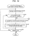
- an autonomous movement control process in the autonomous movement control unit 110 including three types of operation modes, that is, the normal mode, the uncertain-location mode, and the current information self-location estimation mode.
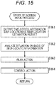
- step S122 by the position change detection process, the position change determination unit 251 of the self-location estimation result switching unit 225 determines whether or not it is notified that there has been detected a position change (a position change unpredictable in advance) of changing to a position indicating, for example, a lifted state (kidnap state).
- a position change a position change unpredictable in advance
- the time-series information self-location is outputted as a self-location estimation result.
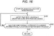
- step S123 the autonomous movement control unit 110 executes an uncertain-location mode process and operates in the uncertain-location mode, and the operation is stopped by continuous notifications that the self-location is uncertain. Note that the uncertain-location mode process will be described later in detail with reference to a flowchart in Fig. 16 .
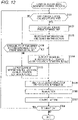
- step S125 it is determined whether or not termination of the operation has been instructed, and the process returns to step S121 in a case where termination has not been instructed. In other words, the processing in steps S121 to S125 is repeated until termination is instructed. Then, in step S125, when termination of the process is instructed, the process is terminated. Note that details of the current information self-location estimation mode process will be described later with reference to Fig. 17 .
- the processing of notifying that the self-location estimation result is uncertain-location is repeated until a predetermined time elapses. Then, when the predetermined time has elapsed and it becomes possible to transition to the current information self-location estimation mode, the operation mode transitions to the current information self-location estimation mode.
- step S183 the self-location estimation result switching unit 225 outputs a current information self-location, which is an estimation result of the current information self-location estimation unit 223, to the situation analysis unit 133 as a self-location estimation result.
- step S188 the self-location estimation result switching unit 225 resets past time-series information registered in the time-series information DB 222, the current information self-location estimation mode process is terminated, and the process returns to step S125 in Fig. 14 .
- the self-location estimation result switching unit 225 may calculate a position change amount for the past x seconds on the basis of a sensor value and the like, and may consider that transition from the right-after-accident mode to the control recovery mode is possible when a time average of the position change amount falls below a predetermined amount.
Landscapes
- Engineering & Computer Science (AREA)
- Physics & Mathematics (AREA)
- General Physics & Mathematics (AREA)
- Remote Sensing (AREA)
- Radar, Positioning & Navigation (AREA)
- Automation & Control Theory (AREA)
- Aviation & Aerospace Engineering (AREA)
- Theoretical Computer Science (AREA)
- Software Systems (AREA)
- Artificial Intelligence (AREA)
- General Health & Medical Sciences (AREA)
- Molecular Biology (AREA)
- Computing Systems (AREA)
- General Engineering & Computer Science (AREA)
- Biomedical Technology (AREA)
- Mathematical Physics (AREA)
- Biophysics (AREA)
- Data Mining & Analysis (AREA)
- Computational Linguistics (AREA)
- Evolutionary Computation (AREA)
- Life Sciences & Earth Sciences (AREA)
- Health & Medical Sciences (AREA)
- Electromagnetism (AREA)
- Computer Vision & Pattern Recognition (AREA)
- Multimedia (AREA)
- Control Of Position, Course, Altitude, Or Attitude Of Moving Bodies (AREA)
- Optics & Photonics (AREA)
- Navigation (AREA)
- Traffic Control Systems (AREA)
Claims (8)
- Mobiles Objekt (11), das Folgendes umfasst:eine Eigenpositionsdetektionseinheit (226), ausgelegt zum Detektieren einer Eigenposition des mobilen Objekts (11) auf einer Grundlage erster Sensorinformationen;eine Positionsänderungsdetektionseinheit (228), ausgelegt zum Detektieren einer im Voraus unvorhersehbaren Positionsänderung auf einer Grundlage eines Detektionsergebnisses durch die Eigenpositionsdetektionseinheit, wobei die Positionsänderungsdetektionseinheit (228) eine Positionsänderung zu einem angehobenen Zustand als die im Voraus unvorhersehbare Positionsänderung detektiert;eine Eigenstandortschätzeinheit, ausgelegt zum Schätzen eines Eigenstandorts mit einem ersten Schätzungsmodell auf einer Grundlage zweiter Sensorinformationen undSchätzen eines Eigenstandorts mit einem zweiten Schätzungsmodell, das sich von dem ersten Schätzungsmodell unterscheidet, falls eine im Voraus unvorhersehbare Positionsänderung durch die Positionsänderungsdetektionseinheit (228) detektiert wird;eine Handlungsplanerzeugungseinheit, ausgelegt zum Erzeugen eines Handlungsplans auf einer Grundlage einer peripheren Situation eines durch die Eigenstandortschätzeinheit geschätzten Eigenstandorts;undeine Steuereinheit, ausgelegt zum Steuern eines Betriebs des mobilen Objekts (11) auf einer Grundlage eines durch die Handlungsplanerzeugungseinheit bestimmten Handlungsplans,dadurch gekennzeichnet, dass die Eigenpositionsschätzeinheit Folgendes beinhaltet:eine Zeitreiheninformationsakkumulationseinheit, die mit den zweiten Sensorinformationen erfasste Informationen als Zeitreihe akkumuliert;eine Zeitreiheninformationseigenstandortschätzeinheit (221), ausgelegt zum Verwenden von in der Zeitreiheninformationsakkumulationseinheit akkumulierten Zeitreiheninformationen zum Schätzen des Eigenstandorts und Ausgeben eines Schätzergebnisses als einen Zeitreiheninformationseigenstandort; undeine Aktuelle-Informationen-Eigenstandortschätzeinheit (223), ausgelegt zum Schätzen des Eigenstandorts auf einer Grundlage aktueller Informationen, bei denen es sich um mit den zweiten Sensorinformationen erfasste aktuelle Informationen handelt, und Ausgeben als Aktuelle-Informationen-Eigenstandort, undwobei die Eigenstandortschätzeinheitden Zeitreiheninformationseigenstandort als Eigenstandortschätzergebnis verwendet, falls die im Voraus unvorhersehbare Positionsänderung nicht detektiert wird, undden Aktuelle-Informationen-Eigenstandort als Eigenstandortschätzergebnis verwendet, falls die im Voraus unvorhersehbare Positionsänderung detektiert wird.
- Mobiles Objekt (11) nach Anspruch 1, wobei die Eigenstandortschätzeinheiteinen Übergang eines Betriebsmodus zu zumindest einem ersten Modus, einem zweiten Modus und einem dritten Modus gemäß einem Detektionsergebnis der Positionsänderungsdetektionseinheit (228) bewirkt;den Betriebsmodus zu Beginn eines Betriebs auf den ersten Modus einstellt und den Eigenstandort mit dem ersten Schätzungsmodell schätzt;in einem ersten Modus einen Übergang des Betriebsmodus zu dem zweiten Modus bewirkt und mitteilt, dass die im Voraus unvorhersehbare Positionsänderung detektiert wurde, falls die im Voraus unvorhersehbare Positionsänderung durch die Positionsänderungsdetektionseinheit (228) detektiert wird;in dem zweiten Modus nach Ablauf einer vorbestimmten Zeit einen Übergang des Betriebsmodus zu dem dritten Modus bewirkt und den Eigenstandort mit dem zweiten Schätzungsmodell schätzt; undin dem dritten Modus nach Ablauf einer vorbestimmten Zeit einen Übergang des Betriebsmodus zu dem ersten Modus bewirkt.
- Mobiles Objekt (11) nach Anspruch 2, wobei die Eigenstandortschätzeinheitin dem ersten Modus als Eigenstandortschätzergebnis den durch die Zeitreiheninformationseigenstandortschätzeinheit (221) unter Verwendung von in der Zeitreiheninformationsakkumulationseinheit akkumulierten Zeitreiheninformationen als das erste Schätzungsmodell geschätzten Zeitreiheninformationseigenstandort verwendet; undin dem dritten Modus als Eigenstandortschätzergebnis den durch die Aktuelle-Informationen-Eigenstandortschätzeinheit (223) unter Verwendung der aktuellen Informationen als das zweite Schätzungsmodell geschätzten Aktuelle-Informationen-Eigenstandort verwendet.
- Mobiles Objekt (11) nach Anspruch 3, wobei die Zeitreiheninformationen durch LIDAR (201) detektierte dreidimensionale Punktwolkeninformationen und Standortinformationen, eine Position, eine Geschwindigkeit, eine Beschleunigung und eine Winkelgeschwindigkeit, detektiert durch einen Radmessgeber (202), beinhalten,die Zeitreiheninformationseigenstandortschätzeinheit (221) den Eigenstandort durch Verwenden eines Kalman-Filters oder eines Partikelfilters auf einer Grundlage der Zeitreiheninformationen schätzt und ein Schätzergebnis als Zeitreiheninformationseigenstandort ausgibt,die aktuellen Informationen ein durch eine Stereokamera (203) aufgenommenes Parallaxenbild beinhalten unddie Aktuelle-Informationen-Eigenstandortschätzeinheit (223) ein Tiefenbild aus dem Parallaxenbild erzeugt, einen Bildmerkmalsbetrag aus dem Tiefenbild extrahiert, einen Eigenstandort auf einer Grundlage des Bildmerkmalsbetrags schätzt und ein Schätzergebnis als Aktuelle-Informationen-Eigenstandort ausgibt.
- Mobiles Objekt (11) nach Anspruch 1, wobei die ersten Sensorinformationen eine Vertikalbeschleunigung beinhalten und
die Eigenpositionsdetektionseinheit (226) Folgendes beinhaltet:eine Frequenzkomponentenextraktionseinheit (271), ausgelegt zum Extrahieren einer Frequenzkomponente einer Änderung der Vertikalbeschleunigung;eine Merkmalsbetragsextraktionseinheit (272), ausgelegt zum Extrahieren eines Merkmalsbetrags aus einer durch die Frequenzkomponentenextraktionseinheit (271) extrahierten Frequenzkomponente; undeine Positionsdetektionseinheit (273), ausgelegt zum Detektieren der Eigenposition auf einer Grundlage des Merkmalsbetrags. - Mobiles Objekt (11) nach Anspruch 5, das ferner Folgendes umfasst:eine Datenbank, in der die Position und ein Merkmalsbetrag der Frequenzkomponente auf einer Grundlage erster Sensorinformationen für eine bekannte Position durch Lernen in Verbindung miteinander registriert sind, wobeidie Positionsdetektionseinheit (273) die Position durch Suchen nach einer entsprechenden Position aus der Datenbank auf einer Grundlage des Merkmalsbetrags detektiert.
- Steuerverfahren für ein mobiles Objekt (11), das Folgendes umfasst:einen Eigenpositionsdetektionsprozess zum Detektieren einer Eigenposition des mobilen Objekts (11) auf einer Grundlage erster Sensorinformationen;einen Positionsänderungsdetektionsprozess zum Detektieren einer im Voraus unvorhersehbaren Positionsänderung auf einer Grundlage eines Detektionsergebnisses durch den Eigenpositionsdetektionsprozess, wobei der Positionsänderungsdetektionsprozess eine Positionsänderung zu einem angehobenen Zustand als die im Voraus unvorhersehbare Positionsänderung detektiert;einen Eigenstandortschätzprozess zum Schätzen eines Eigenstandorts mit einem ersten Schätzungsmodell auf einer Grundlage zweiter Sensorinformationen undSchätzen eines Eigenstandorts mit einem zweiten Schätzungsmodell, das sich von dem ersten Schätzungsmodell unterscheidet, falls eine im Voraus unvorhersehbare Positionsänderung durch den Positionsänderungsdetektionsprozess detektiert wird;einen Handlungsplanerzeugungsprozess zum Erzeugen eines Handlungsplans auf einer Grundlage einer peripheren Situation eines durch die Eigenstandortschätzeinheit geschätzten Eigenstandorts; undeinen Steuerprozess zum Steuern eines Betriebs des mobilen Objekts (11) auf einer Grundlage eines durch die Handlungsplanerzeugungseinheit bestimmten Handlungsplans,dadurch gekennzeichnet, dass der Eigenpositionsschätzprozess Folgendes beinhaltet:einen Zeitreiheninformationsakkumulationsprozess zum Akkumulieren von mit den zweiten Sensorinformationen erfassten Informationen als Zeitreihe;einen Zeitreiheninformationseigenstandortschätzprozess zum Verwenden von in dem Zeitreiheninformationsakkumulationsprozess akkumulierten Zeitreiheninformationen zum Schätzen des Eigenstandorts und Ausgeben eines Schätzergebnisses als einen Zeitreiheninformationseigenstandort; undeinen Aktuelle-Informationen-Eigenstandortschätzprozess zum Schätzen des Eigenstandorts auf einer Grundlage aktueller Informationen, bei denen es sich um mit den zweiten Sensorinformationen erfasste aktuelle Informationen handelt, und Ausgeben als Aktuelle-Informationen-Eigenstandort, undwobei der Eigenstandortschätzprozessden Zeitreiheninformationseigenstandort als Eigenstandortschätzergebnis verwendet, falls die im Voraus unvorhersehbare Positionsänderung nicht detektiert wird, undden Aktuelle-Informationen-Eigenstandort als Eigenstandortschätzergebnis verwendet, falls die im Voraus unvorhersehbare Positionsänderung detektiert wird.
- Programm zum Bewirken, dass ein Computer als Folgendes wirkt:eine Eigenpositionsdetektionseinheit, ausgelegt zum Detektieren einer Eigenposition eines mobilen Objekts (11) auf einer Grundlage erster Sensorinformationen;eine Positionsänderungsdetektionseinheit, ausgelegt zum Detektieren einer im Voraus unvorhersehbaren Positionsänderung auf einer Grundlage eines Detektionsergebnisses durch die Eigenpositionsdetektionseinheit, wobei die Positionsänderungsdetektionseinheit eine Positionsänderung zu einem angehobenen Zustand als die im Voraus unvorhersehbare Positionsänderung detektiert;eine Eigenstandortschätzeinheit, ausgelegt zum Schätzen eines Eigenstandorts mit einem ersten Schätzungsmodell auf einer Grundlage zweiter Sensorinformationen undSchätzen eines Eigenstandorts mit einem zweiten Schätzungsmodell, das sich von dem ersten Schätzungsmodell unterscheidet, falls eine im Voraus unvorhersehbare Positionsänderung durch die Positionsänderungsdetektionseinheit detektiert wird;eine Handlungsplanerzeugungseinheit, ausgelegt zum Erzeugen eines Handlungsplans auf einer Grundlage einer peripheren Situation eines durch die Eigenstandortschätzeinheit geschätzten Eigenstandorts;undeine Steuereinheit, ausgelegt zum Steuern eines Betriebs des mobilen Objekts (11) auf einer Grundlage eines durch die Handlungsplanerzeugungseinheit bestimmten Handlungsplans,dadurch gekennzeichnet, dass die Eigenpositionsschätzeinheit Folgendes beinhaltet:eine Zeitreiheninformationsakkumulationseinheit, die mit den zweiten Sensorinformationen erfasste Informationen als Zeitreihe akkumuliert;eine Zeitreiheninformationseigenstandortschätzeinheit, ausgelegt zum Verwenden von in der Zeitreiheninformationsakkumulationseinheit akkumulierten Zeitreiheninformationen zum Schätzen des Eigenstandorts und Ausgeben eines Schätzergebnisses als einen Zeitreiheninformationseigenstandort; undeine Aktuelle-Informationen-Eigenstandortschätzeinheit, ausgelegt zum Schätzen des Eigenstandorts auf einer Grundlage aktueller Informationen, bei denen es sich um mit den zweiten Sensorinformationen erfasste aktuelle Informationen handelt, und Ausgeben als Aktuelle-Informationen-Eigenstandort, undwobei die Eigenstandortschätzeinheitden Zeitreiheninformationseigenstandort als Eigenstandortschätzergebnis verwendet, falls die im Voraus unvorhersehbare Positionsänderung nicht detektiert wird, undden Aktuelle-Informationen-Eigenstandort als Eigenstandortschätzergebnis verwendet, falls die im Voraus unvorhersehbare Positionsänderung detektiert wird.
Applications Claiming Priority (2)
| Application Number | Priority Date | Filing Date | Title |
|---|---|---|---|
| JP2017233094 | 2017-12-05 | ||
| PCT/JP2018/042921 WO2019111701A1 (ja) | 2017-12-05 | 2018-11-21 | 制御装置、および制御方法、プログラム、並びに移動体 |
Publications (3)
| Publication Number | Publication Date |
|---|---|
| EP3722904A1 EP3722904A1 (de) | 2020-10-14 |
| EP3722904A4 EP3722904A4 (de) | 2021-01-06 |
| EP3722904B1 true EP3722904B1 (de) | 2022-06-01 |
Family
ID=66750936
Family Applications (1)
| Application Number | Title | Priority Date | Filing Date |
|---|---|---|---|
| EP18885277.6A Not-in-force EP3722904B1 (de) | 2017-12-05 | 2018-11-21 | Bewegliches fahrzeug, steuerverfahren und steuerprogramm |
Country Status (5)
| Country | Link |
|---|---|
| US (1) | US11592829B2 (de) |
| EP (1) | EP3722904B1 (de) |
| JP (1) | JP7180612B2 (de) |
| KR (1) | KR102625488B1 (de) |
| WO (1) | WO2019111701A1 (de) |
Families Citing this family (14)
| Publication number | Priority date | Publication date | Assignee | Title |
|---|---|---|---|---|
| JP7175216B2 (ja) * | 2019-02-15 | 2022-11-18 | ルネサスエレクトロニクス株式会社 | 異常検知装置、異常検知システム、異常検知方法 |
| WO2020223908A1 (en) * | 2019-05-07 | 2020-11-12 | Nokia Technologies Oy | Privacy management |
| JP7385388B2 (ja) * | 2019-07-22 | 2023-11-22 | 株式会社ダイヘン | 自己位置推定装置 |
| JP2021060669A (ja) * | 2019-10-03 | 2021-04-15 | ソニー株式会社 | 情報処理装置、情報処理方法、情報処理システム及びプログラム |
| FR3106665B1 (fr) * | 2020-01-27 | 2022-02-18 | Continental Automotive | Procédé et dispositif de localisation d’un véhicule |
| WO2022014485A1 (ja) * | 2020-07-14 | 2022-01-20 | 国立大学法人筑波大学 | 情報処理装置、方法、及びプログラム |
| US11833661B2 (en) * | 2020-10-31 | 2023-12-05 | Google Llc | Utilizing past contact physics in robotic manipulation (e.g., pushing) of an object |
| KR102434973B1 (ko) * | 2020-11-06 | 2022-08-22 | 한국항공우주연구원 | 우주탐사장비의 이상 검출 방법 |
| JP7494724B2 (ja) * | 2020-12-18 | 2024-06-04 | トヨタ自動車株式会社 | 自動運転車両 |
| CN112687173B (zh) * | 2020-12-25 | 2022-06-21 | 安徽机电职业技术学院 | 一种基于主被动安全协同优化的汽车碰撞演示平台 |
| US12377871B2 (en) * | 2021-03-30 | 2025-08-05 | Applied Intuition, Inc. | Scheduling state transitions in an autonomous vehicle |
| JP7156445B1 (ja) | 2021-05-18 | 2022-10-19 | 三菱電機株式会社 | 携帯端末、歩行ロボット、プログラム、および位置演算支援方法 |
| EP4522506A1 (de) * | 2022-05-13 | 2025-03-19 | Oshkosh Aerotech, LLC | Techniken der künstlichen intelligenz zum autonomen betrieb von passagiereinstiegsbrücken |
| CN117115254A (zh) * | 2023-08-23 | 2023-11-24 | 上海大学 | 一种用于执行slam任务时的仿生眼双目视觉的主动定位方法 |
Family Cites Families (14)
| Publication number | Priority date | Publication date | Assignee | Title |
|---|---|---|---|---|
| JPS5239467Y2 (de) | 1971-03-31 | 1977-09-07 | ||
| US7103460B1 (en) | 1994-05-09 | 2006-09-05 | Automotive Technologies International, Inc. | System and method for vehicle diagnostics |
| WO2004016400A2 (en) * | 2002-08-16 | 2004-02-26 | Evolution Robotics, Inc. | Systems and methods for the automated sensing of motion in a mobile robot using visual data |
| US7689321B2 (en) * | 2004-02-13 | 2010-03-30 | Evolution Robotics, Inc. | Robust sensor fusion for mapping and localization in a simultaneous localization and mapping (SLAM) system |
| KR101297388B1 (ko) | 2006-06-16 | 2013-08-19 | 삼성전자주식회사 | 위치 보정 기능을 제공하는 이동 장치 및 위치 보정 방법 |
| KR100941418B1 (ko) * | 2007-03-20 | 2010-02-11 | 삼성전자주식회사 | 이동 로봇의 위치 인식 방법 |
| CN102083352B (zh) * | 2008-04-24 | 2014-10-15 | 艾罗伯特公司 | 用于机器人使能的移动产品的定位、位置控制和导航系统的应用 |
| JP5141507B2 (ja) * | 2008-08-25 | 2013-02-13 | 村田機械株式会社 | 自律移動装置 |
| JP5168134B2 (ja) | 2008-12-26 | 2013-03-21 | 富士通株式会社 | 環境地図生成プログラム、環境地図生成方法及び移動ロボット |
| CN101509781B (zh) * | 2009-03-20 | 2011-09-14 | 同济大学 | 基于单目摄像头的步行机器人定位系统 |
| US9014848B2 (en) | 2010-05-20 | 2015-04-21 | Irobot Corporation | Mobile robot system |
| JP2013045298A (ja) | 2011-08-24 | 2013-03-04 | Hitachi Plant Technologies Ltd | 無人搬送車 |
| WO2013071190A1 (en) | 2011-11-11 | 2013-05-16 | Evolution Robotics, Inc. | Scaling vector field slam to large environments |
| JP6658001B2 (ja) | 2016-01-27 | 2020-03-04 | 株式会社リコー | 位置推定装置、プログラム、位置推定方法 |
-
2018
- 2018-11-21 WO PCT/JP2018/042921 patent/WO2019111701A1/ja not_active Ceased
- 2018-11-21 US US16/767,593 patent/US11592829B2/en active Active
- 2018-11-21 EP EP18885277.6A patent/EP3722904B1/de not_active Not-in-force
- 2018-11-21 KR KR1020207014651A patent/KR102625488B1/ko active Active
- 2018-11-21 JP JP2019558116A patent/JP7180612B2/ja active Active
Also Published As
| Publication number | Publication date |
|---|---|
| US11592829B2 (en) | 2023-02-28 |
| JP7180612B2 (ja) | 2022-11-30 |
| JPWO2019111701A1 (ja) | 2020-11-26 |
| US20200387162A1 (en) | 2020-12-10 |
| KR102625488B1 (ko) | 2024-01-17 |
| EP3722904A1 (de) | 2020-10-14 |
| KR20200090777A (ko) | 2020-07-29 |
| WO2019111701A1 (ja) | 2019-06-13 |
| EP3722904A4 (de) | 2021-01-06 |
Similar Documents
| Publication | Publication Date | Title |
|---|---|---|
| US11592829B2 (en) | Control device and control method, program, and mobile object | |
| US11537131B2 (en) | Control device, control method, and mobile body | |
| US11822334B2 (en) | Information processing apparatus, information processing method, and program for control of a moving body capable of autonomous movement | |
| US11822341B2 (en) | Control device, control method, and mobile object to estimate the mobile object's self-position | |
| JP7180670B2 (ja) | 制御装置、制御方法、並びにプログラム | |
| US11906970B2 (en) | Information processing device and information processing method | |
| US12217512B2 (en) | Information processing apparatus and information processing method | |
| KR20220020804A (ko) | 정보 처리 장치 및 정보 처리 방법, 그리고 프로그램 | |
| US20200231176A1 (en) | Control apparatus, control method, program, and moving body | |
| JP7257737B2 (ja) | 情報処理装置、自己位置推定方法、及び、プログラム | |
| US11500386B2 (en) | Control apparatus, control method, program, and mobile object | |
| US12259949B2 (en) | Information processing device, information processing method, and program | |
| US20200230820A1 (en) | Information processing apparatus, self-localization method, program, and mobile body | |
| US20200278208A1 (en) | Information processing apparatus, movable apparatus, information processing method, movable-apparatus control method, and programs | |
| US20240257508A1 (en) | Information processing device, information processing method, and program | |
| US20220111873A1 (en) | Autonomous vehicle system for detecting pedestrian presence | |
| WO2021140916A1 (ja) | 移動体、情報処理装置、情報処理方法、及びプログラム |
Legal Events
| Date | Code | Title | Description |
|---|---|---|---|
| STAA | Information on the status of an ep patent application or granted ep patent |
Free format text: STATUS: THE INTERNATIONAL PUBLICATION HAS BEEN MADE |
|
| PUAI | Public reference made under article 153(3) epc to a published international application that has entered the european phase |
Free format text: ORIGINAL CODE: 0009012 |
|
| STAA | Information on the status of an ep patent application or granted ep patent |
Free format text: STATUS: REQUEST FOR EXAMINATION WAS MADE |
|
| 17P | Request for examination filed |
Effective date: 20200529 |
|
| AK | Designated contracting states |
Kind code of ref document: A1 Designated state(s): AL AT BE BG CH CY CZ DE DK EE ES FI FR GB GR HR HU IE IS IT LI LT LU LV MC MK MT NL NO PL PT RO RS SE SI SK SM TR |
|
| AX | Request for extension of the european patent |
Extension state: BA ME |
|
| A4 | Supplementary search report drawn up and despatched |
Effective date: 20201209 |
|
| RIC1 | Information provided on ipc code assigned before grant |
Ipc: G05D 1/02 20200101AFI20201203BHEP |
|
| DAV | Request for validation of the european patent (deleted) | ||
| DAX | Request for extension of the european patent (deleted) | ||
| RAP3 | Party data changed (applicant data changed or rights of an application transferred) |
Owner name: SONY GROUP CORPORATION |
|
| GRAP | Despatch of communication of intention to grant a patent |
Free format text: ORIGINAL CODE: EPIDOSNIGR1 |
|
| STAA | Information on the status of an ep patent application or granted ep patent |
Free format text: STATUS: GRANT OF PATENT IS INTENDED |
|
| INTG | Intention to grant announced |
Effective date: 20211221 |
|
| GRAS | Grant fee paid |
Free format text: ORIGINAL CODE: EPIDOSNIGR3 |
|
| GRAA | (expected) grant |
Free format text: ORIGINAL CODE: 0009210 |
|
| STAA | Information on the status of an ep patent application or granted ep patent |
Free format text: STATUS: THE PATENT HAS BEEN GRANTED |
|
| AK | Designated contracting states |
Kind code of ref document: B1 Designated state(s): AL AT BE BG CH CY CZ DE DK EE ES FI FR GB GR HR HU IE IS IT LI LT LU LV MC MK MT NL NO PL PT RO RS SE SI SK SM TR |
|
| REG | Reference to a national code |
Ref country code: GB Ref legal event code: FG4D |
|
| REG | Reference to a national code |
Ref country code: AT Ref legal event code: REF Ref document number: 1495834 Country of ref document: AT Kind code of ref document: T Effective date: 20220615 Ref country code: CH Ref legal event code: EP |
|
| REG | Reference to a national code |
Ref country code: IE Ref legal event code: FG4D |
|
| REG | Reference to a national code |
Ref country code: DE Ref legal event code: R096 Ref document number: 602018036359 Country of ref document: DE |
|
| REG | Reference to a national code |
Ref country code: LT Ref legal event code: MG9D |
|
| REG | Reference to a national code |
Ref country code: NL Ref legal event code: MP Effective date: 20220601 |
|
| PG25 | Lapsed in a contracting state [announced via postgrant information from national office to epo] |
Ref country code: SE Free format text: LAPSE BECAUSE OF FAILURE TO SUBMIT A TRANSLATION OF THE DESCRIPTION OR TO PAY THE FEE WITHIN THE PRESCRIBED TIME-LIMIT Effective date: 20220601 Ref country code: NO Free format text: LAPSE BECAUSE OF FAILURE TO SUBMIT A TRANSLATION OF THE DESCRIPTION OR TO PAY THE FEE WITHIN THE PRESCRIBED TIME-LIMIT Effective date: 20220901 Ref country code: LT Free format text: LAPSE BECAUSE OF FAILURE TO SUBMIT A TRANSLATION OF THE DESCRIPTION OR TO PAY THE FEE WITHIN THE PRESCRIBED TIME-LIMIT Effective date: 20220601 Ref country code: HR Free format text: LAPSE BECAUSE OF FAILURE TO SUBMIT A TRANSLATION OF THE DESCRIPTION OR TO PAY THE FEE WITHIN THE PRESCRIBED TIME-LIMIT Effective date: 20220601 Ref country code: GR Free format text: LAPSE BECAUSE OF FAILURE TO SUBMIT A TRANSLATION OF THE DESCRIPTION OR TO PAY THE FEE WITHIN THE PRESCRIBED TIME-LIMIT Effective date: 20220902 Ref country code: FI Free format text: LAPSE BECAUSE OF FAILURE TO SUBMIT A TRANSLATION OF THE DESCRIPTION OR TO PAY THE FEE WITHIN THE PRESCRIBED TIME-LIMIT Effective date: 20220601 Ref country code: ES Free format text: LAPSE BECAUSE OF FAILURE TO SUBMIT A TRANSLATION OF THE DESCRIPTION OR TO PAY THE FEE WITHIN THE PRESCRIBED TIME-LIMIT Effective date: 20220601 Ref country code: BG Free format text: LAPSE BECAUSE OF FAILURE TO SUBMIT A TRANSLATION OF THE DESCRIPTION OR TO PAY THE FEE WITHIN THE PRESCRIBED TIME-LIMIT Effective date: 20220901 |
|
| REG | Reference to a national code |
Ref country code: AT Ref legal event code: MK05 Ref document number: 1495834 Country of ref document: AT Kind code of ref document: T Effective date: 20220601 |
|
| PG25 | Lapsed in a contracting state [announced via postgrant information from national office to epo] |
Ref country code: RS Free format text: LAPSE BECAUSE OF FAILURE TO SUBMIT A TRANSLATION OF THE DESCRIPTION OR TO PAY THE FEE WITHIN THE PRESCRIBED TIME-LIMIT Effective date: 20220601 Ref country code: PL Free format text: LAPSE BECAUSE OF FAILURE TO SUBMIT A TRANSLATION OF THE DESCRIPTION OR TO PAY THE FEE WITHIN THE PRESCRIBED TIME-LIMIT Effective date: 20220601 Ref country code: LV Free format text: LAPSE BECAUSE OF FAILURE TO SUBMIT A TRANSLATION OF THE DESCRIPTION OR TO PAY THE FEE WITHIN THE PRESCRIBED TIME-LIMIT Effective date: 20220601 |
|
| PG25 | Lapsed in a contracting state [announced via postgrant information from national office to epo] |
Ref country code: NL Free format text: LAPSE BECAUSE OF FAILURE TO SUBMIT A TRANSLATION OF THE DESCRIPTION OR TO PAY THE FEE WITHIN THE PRESCRIBED TIME-LIMIT Effective date: 20220601 |
|
| PG25 | Lapsed in a contracting state [announced via postgrant information from national office to epo] |
Ref country code: SM Free format text: LAPSE BECAUSE OF FAILURE TO SUBMIT A TRANSLATION OF THE DESCRIPTION OR TO PAY THE FEE WITHIN THE PRESCRIBED TIME-LIMIT Effective date: 20220601 Ref country code: SK Free format text: LAPSE BECAUSE OF FAILURE TO SUBMIT A TRANSLATION OF THE DESCRIPTION OR TO PAY THE FEE WITHIN THE PRESCRIBED TIME-LIMIT Effective date: 20220601 Ref country code: RO Free format text: LAPSE BECAUSE OF FAILURE TO SUBMIT A TRANSLATION OF THE DESCRIPTION OR TO PAY THE FEE WITHIN THE PRESCRIBED TIME-LIMIT Effective date: 20220601 Ref country code: PT Free format text: LAPSE BECAUSE OF FAILURE TO SUBMIT A TRANSLATION OF THE DESCRIPTION OR TO PAY THE FEE WITHIN THE PRESCRIBED TIME-LIMIT Effective date: 20221003 Ref country code: EE Free format text: LAPSE BECAUSE OF FAILURE TO SUBMIT A TRANSLATION OF THE DESCRIPTION OR TO PAY THE FEE WITHIN THE PRESCRIBED TIME-LIMIT Effective date: 20220601 Ref country code: CZ Free format text: LAPSE BECAUSE OF FAILURE TO SUBMIT A TRANSLATION OF THE DESCRIPTION OR TO PAY THE FEE WITHIN THE PRESCRIBED TIME-LIMIT Effective date: 20220601 Ref country code: AT Free format text: LAPSE BECAUSE OF FAILURE TO SUBMIT A TRANSLATION OF THE DESCRIPTION OR TO PAY THE FEE WITHIN THE PRESCRIBED TIME-LIMIT Effective date: 20220601 |
|
| PGFP | Annual fee paid to national office [announced via postgrant information from national office to epo] |
Ref country code: DE Payment date: 20221020 Year of fee payment: 5 |
|
| PG25 | Lapsed in a contracting state [announced via postgrant information from national office to epo] |
Ref country code: IS Free format text: LAPSE BECAUSE OF FAILURE TO SUBMIT A TRANSLATION OF THE DESCRIPTION OR TO PAY THE FEE WITHIN THE PRESCRIBED TIME-LIMIT Effective date: 20221001 |
|
| REG | Reference to a national code |
Ref country code: DE Ref legal event code: R097 Ref document number: 602018036359 Country of ref document: DE |
|
| PG25 | Lapsed in a contracting state [announced via postgrant information from national office to epo] |
Ref country code: AL Free format text: LAPSE BECAUSE OF FAILURE TO SUBMIT A TRANSLATION OF THE DESCRIPTION OR TO PAY THE FEE WITHIN THE PRESCRIBED TIME-LIMIT Effective date: 20220601 |
|
| PLBE | No opposition filed within time limit |
Free format text: ORIGINAL CODE: 0009261 |
|
| STAA | Information on the status of an ep patent application or granted ep patent |
Free format text: STATUS: NO OPPOSITION FILED WITHIN TIME LIMIT |
|
| PG25 | Lapsed in a contracting state [announced via postgrant information from national office to epo] |
Ref country code: DK Free format text: LAPSE BECAUSE OF FAILURE TO SUBMIT A TRANSLATION OF THE DESCRIPTION OR TO PAY THE FEE WITHIN THE PRESCRIBED TIME-LIMIT Effective date: 20220601 |
|
| 26N | No opposition filed |
Effective date: 20230302 |
|
| PG25 | Lapsed in a contracting state [announced via postgrant information from national office to epo] |
Ref country code: SI Free format text: LAPSE BECAUSE OF FAILURE TO SUBMIT A TRANSLATION OF THE DESCRIPTION OR TO PAY THE FEE WITHIN THE PRESCRIBED TIME-LIMIT Effective date: 20220601 |
|
| PG25 | Lapsed in a contracting state [announced via postgrant information from national office to epo] |
Ref country code: MC Free format text: LAPSE BECAUSE OF FAILURE TO SUBMIT A TRANSLATION OF THE DESCRIPTION OR TO PAY THE FEE WITHIN THE PRESCRIBED TIME-LIMIT Effective date: 20220601 |
|
| REG | Reference to a national code |
Ref country code: CH Ref legal event code: PL |
|
| P01 | Opt-out of the competence of the unified patent court (upc) registered |
Effective date: 20230528 |
|
| GBPC | Gb: european patent ceased through non-payment of renewal fee |
Effective date: 20221121 |
|
| REG | Reference to a national code |
Ref country code: BE Ref legal event code: MM Effective date: 20221130 |
|
| PG25 | Lapsed in a contracting state [announced via postgrant information from national office to epo] |
Ref country code: LI Free format text: LAPSE BECAUSE OF NON-PAYMENT OF DUE FEES Effective date: 20221130 Ref country code: CH Free format text: LAPSE BECAUSE OF NON-PAYMENT OF DUE FEES Effective date: 20221130 |
|
| PG25 | Lapsed in a contracting state [announced via postgrant information from national office to epo] |
Ref country code: LU Free format text: LAPSE BECAUSE OF NON-PAYMENT OF DUE FEES Effective date: 20221121 |
|
| PG25 | Lapsed in a contracting state [announced via postgrant information from national office to epo] |
Ref country code: IE Free format text: LAPSE BECAUSE OF NON-PAYMENT OF DUE FEES Effective date: 20221121 Ref country code: GB Free format text: LAPSE BECAUSE OF NON-PAYMENT OF DUE FEES Effective date: 20221121 |
|
| REG | Reference to a national code |
Ref country code: DE Ref legal event code: R079 Ref document number: 602018036359 Country of ref document: DE Free format text: PREVIOUS MAIN CLASS: G05D0001020000 Ipc: G05D0001430000 |
|
| PG25 | Lapsed in a contracting state [announced via postgrant information from national office to epo] |
Ref country code: FR Free format text: LAPSE BECAUSE OF NON-PAYMENT OF DUE FEES Effective date: 20221130 Ref country code: BE Free format text: LAPSE BECAUSE OF NON-PAYMENT OF DUE FEES Effective date: 20221130 |
|
| PG25 | Lapsed in a contracting state [announced via postgrant information from national office to epo] |
Ref country code: IT Free format text: LAPSE BECAUSE OF FAILURE TO SUBMIT A TRANSLATION OF THE DESCRIPTION OR TO PAY THE FEE WITHIN THE PRESCRIBED TIME-LIMIT Effective date: 20220601 |
|
| PG25 | Lapsed in a contracting state [announced via postgrant information from national office to epo] |
Ref country code: CY Free format text: LAPSE BECAUSE OF FAILURE TO SUBMIT A TRANSLATION OF THE DESCRIPTION OR TO PAY THE FEE WITHIN THE PRESCRIBED TIME-LIMIT Effective date: 20220601 |
|
| PG25 | Lapsed in a contracting state [announced via postgrant information from national office to epo] |
Ref country code: MK Free format text: LAPSE BECAUSE OF FAILURE TO SUBMIT A TRANSLATION OF THE DESCRIPTION OR TO PAY THE FEE WITHIN THE PRESCRIBED TIME-LIMIT Effective date: 20220601 Ref country code: HU Free format text: LAPSE BECAUSE OF FAILURE TO SUBMIT A TRANSLATION OF THE DESCRIPTION OR TO PAY THE FEE WITHIN THE PRESCRIBED TIME-LIMIT; INVALID AB INITIO Effective date: 20181121 |
|
| REG | Reference to a national code |
Ref country code: DE Ref legal event code: R119 Ref document number: 602018036359 Country of ref document: DE |
|
| PG25 | Lapsed in a contracting state [announced via postgrant information from national office to epo] |
Ref country code: MT Free format text: LAPSE BECAUSE OF FAILURE TO SUBMIT A TRANSLATION OF THE DESCRIPTION OR TO PAY THE FEE WITHIN THE PRESCRIBED TIME-LIMIT Effective date: 20220601 |
|
| PG25 | Lapsed in a contracting state [announced via postgrant information from national office to epo] |
Ref country code: DE Free format text: LAPSE BECAUSE OF NON-PAYMENT OF DUE FEES Effective date: 20240601 |
|
| PG25 | Lapsed in a contracting state [announced via postgrant information from national office to epo] |
Ref country code: DE Free format text: LAPSE BECAUSE OF NON-PAYMENT OF DUE FEES Effective date: 20240601 |
|
| PG25 | Lapsed in a contracting state [announced via postgrant information from national office to epo] |
Ref country code: BG Free format text: LAPSE BECAUSE OF FAILURE TO SUBMIT A TRANSLATION OF THE DESCRIPTION OR TO PAY THE FEE WITHIN THE PRESCRIBED TIME-LIMIT Effective date: 20220601 |
|
| PG25 | Lapsed in a contracting state [announced via postgrant information from national office to epo] |
Ref country code: BG Free format text: LAPSE BECAUSE OF FAILURE TO SUBMIT A TRANSLATION OF THE DESCRIPTION OR TO PAY THE FEE WITHIN THE PRESCRIBED TIME-LIMIT Effective date: 20220601 |
|
| PG25 | Lapsed in a contracting state [announced via postgrant information from national office to epo] |
Ref country code: TR Free format text: LAPSE BECAUSE OF FAILURE TO SUBMIT A TRANSLATION OF THE DESCRIPTION OR TO PAY THE FEE WITHIN THE PRESCRIBED TIME-LIMIT Effective date: 20220601 |