EP3722905A1 - Système de génération d'itinéraire cible pour véhicule de travail - Google Patents
Système de génération d'itinéraire cible pour véhicule de travail Download PDFInfo
- Publication number
- EP3722905A1 EP3722905A1 EP18886134.8A EP18886134A EP3722905A1 EP 3722905 A1 EP3722905 A1 EP 3722905A1 EP 18886134 A EP18886134 A EP 18886134A EP 3722905 A1 EP3722905 A1 EP 3722905A1
- Authority
- EP
- European Patent Office
- Prior art keywords
- target route
- route
- target
- work
- area
- Prior art date
- Legal status (The legal status is an assumption and is not a legal conclusion. Google has not performed a legal analysis and makes no representation as to the accuracy of the status listed.)
- Granted
Links
Images




Classifications
-
- G—PHYSICS
- G05—CONTROLLING; REGULATING
- G05D—SYSTEMS FOR CONTROLLING OR REGULATING NON-ELECTRIC VARIABLES
- G05D1/00—Control of position, course, altitude or attitude of land, water, air or space vehicles, e.g. using automatic pilots
- G05D1/02—Control of position or course in two dimensions
- G05D1/021—Control of position or course in two dimensions specially adapted to land vehicles
- G05D1/0212—Control of position or course in two dimensions specially adapted to land vehicles with means for defining a desired trajectory
- G05D1/0219—Control of position or course in two dimensions specially adapted to land vehicles with means for defining a desired trajectory ensuring the processing of the whole working surface
-
- G—PHYSICS
- G05—CONTROLLING; REGULATING
- G05D—SYSTEMS FOR CONTROLLING OR REGULATING NON-ELECTRIC VARIABLES
- G05D1/00—Control of position, course, altitude or attitude of land, water, air or space vehicles, e.g. using automatic pilots
- G05D1/60—Intended control result
- G05D1/644—Optimisation of travel parameters, e.g. of energy consumption, journey time or distance
-
- G—PHYSICS
- G05—CONTROLLING; REGULATING
- G05D—SYSTEMS FOR CONTROLLING OR REGULATING NON-ELECTRIC VARIABLES
- G05D1/00—Control of position, course, altitude or attitude of land, water, air or space vehicles, e.g. using automatic pilots
- G05D1/40—Control within particular dimensions
- G05D1/43—Control of position or course in two dimensions [2D]
-
- A—HUMAN NECESSITIES
- A01—AGRICULTURE; FORESTRY; ANIMAL HUSBANDRY; HUNTING; TRAPPING; FISHING
- A01B—SOIL WORKING IN AGRICULTURE OR FORESTRY; PARTS, DETAILS, OR ACCESSORIES OF AGRICULTURAL MACHINES OR IMPLEMENTS, IN GENERAL
- A01B69/00—Steering of agricultural machines or implements; Guiding agricultural machines or implements on a desired track
-
- A—HUMAN NECESSITIES
- A01—AGRICULTURE; FORESTRY; ANIMAL HUSBANDRY; HUNTING; TRAPPING; FISHING
- A01B—SOIL WORKING IN AGRICULTURE OR FORESTRY; PARTS, DETAILS, OR ACCESSORIES OF AGRICULTURAL MACHINES OR IMPLEMENTS, IN GENERAL
- A01B69/00—Steering of agricultural machines or implements; Guiding agricultural machines or implements on a desired track
- A01B69/007—Steering or guiding of agricultural vehicles, e.g. steering of the tractor to keep the plough in the furrow
- A01B69/008—Steering or guiding of agricultural vehicles, e.g. steering of the tractor to keep the plough in the furrow automatic
-
- G—PHYSICS
- G01—MEASURING; TESTING
- G01C—MEASURING DISTANCES, LEVELS OR BEARINGS; SURVEYING; NAVIGATION; GYROSCOPIC INSTRUMENTS; PHOTOGRAMMETRY OR VIDEOGRAMMETRY
- G01C21/00—Navigation; Navigational instruments not provided for in groups G01C1/00 - G01C19/00
- G01C21/20—Instruments for performing navigational calculations
-
- G—PHYSICS
- G05—CONTROLLING; REGULATING
- G05D—SYSTEMS FOR CONTROLLING OR REGULATING NON-ELECTRIC VARIABLES
- G05D1/00—Control of position, course, altitude or attitude of land, water, air or space vehicles, e.g. using automatic pilots
- G05D1/20—Control system inputs
- G05D1/24—Arrangements for determining position or orientation
- G05D1/247—Arrangements for determining position or orientation using signals provided by artificial sources external to the vehicle, e.g. navigation beacons
-
- G—PHYSICS
- G05—CONTROLLING; REGULATING
- G05D—SYSTEMS FOR CONTROLLING OR REGULATING NON-ELECTRIC VARIABLES
- G05D1/00—Control of position, course, altitude or attitude of land, water, air or space vehicles, e.g. using automatic pilots
- G05D1/20—Control system inputs
- G05D1/24—Arrangements for determining position or orientation
- G05D1/247—Arrangements for determining position or orientation using signals provided by artificial sources external to the vehicle, e.g. navigation beacons
- G05D1/248—Arrangements for determining position or orientation using signals provided by artificial sources external to the vehicle, e.g. navigation beacons generated by satellites, e.g. GPS
-
- G—PHYSICS
- G05—CONTROLLING; REGULATING
- G05D—SYSTEMS FOR CONTROLLING OR REGULATING NON-ELECTRIC VARIABLES
- G05D1/00—Control of position, course, altitude or attitude of land, water, air or space vehicles, e.g. using automatic pilots
- G05D1/60—Intended control result
- G05D1/648—Performing a task within a working area or space, e.g. cleaning
-
- G—PHYSICS
- G05—CONTROLLING; REGULATING
- G05D—SYSTEMS FOR CONTROLLING OR REGULATING NON-ELECTRIC VARIABLES
- G05D2101/00—Details of software or hardware architectures used for the control of position
- G05D2101/10—Details of software or hardware architectures used for the control of position using artificial intelligence [AI] techniques
-
- G—PHYSICS
- G05—CONTROLLING; REGULATING
- G05D—SYSTEMS FOR CONTROLLING OR REGULATING NON-ELECTRIC VARIABLES
- G05D2105/00—Specific applications of the controlled vehicles
- G05D2105/15—Specific applications of the controlled vehicles for harvesting, sowing or mowing in agriculture or forestry
Definitions
- the present invention relates to a target route generation system for a work vehicle that generates a target route for the autonomous travel of a passenger work vehicle such as a tractor, a passenger rice planter, a combine, a passenger mower, a wheel loader, or a snowplow, and an unmanned work vehicle such as an unmanned mower.
- a passenger work vehicle such as a tractor, a passenger rice planter, a combine, a passenger mower, a wheel loader, or a snowplow
- an unmanned work vehicle such as an unmanned mower.
- a route generation apparatus configured to generate a target route for the autonomous travel in accordance with the user's sense of value based on input arbitrary setting data after the user manually inputs, as the arbitrary setting data for the target route generation, a plurality of work area determination points such as the corner positions or the inflection points of a field (work area), the work start position, the work start direction, the work end position, etc. in accordance with the user's sense of value based on the work field data such as the size or the shape of the field that is acquired after a tractor (work vehicle) travels along the outer periphery of the field (see for example Patent Literature 1).
- Patent Literature 1 Japanese Laid-open Patent Publication No. 2017-173986
- the user inputs all the arbitrary setting data necessary for generating a target route. This allows the user who is used to inputting the arbitrary setting data to input the arbitrary setting data in accordance with the user's sense of value, and the like, whereby it is possible to generate a target route in accordance with the user's sense of value, etc. with the target route generation system.
- the principal object of the present invention is to generate a target route for the autonomous travel suitable for the user's sense of value, or the like, without forcing the user to input arbitrary setting data so as to achieve a beneficial work using the autonomous travel.
- a first characteristic configuration of the present invention is that a target route generation system for a work vehicle includes a storage part that stores basic data necessary for generating a target route for autonomous travel, a priority item selection part that prompts selection of a priority item with regard to generation of the target route, and a target route generation part that generates the target route based on the basic data and a selected priority item.
- the target route generation part when the user performs the operation to select the priority item corresponding to his/her sense of value, or the like, with the priority item selection part, the target route generation part generates a target route suitable for the user's sense of value, or the like, based on the basic data stored in the storage part and the priority item selected by the user.
- the user simply performs the operation to select a priority item corresponding to his/her sense of value, or the like, without inputting arbitrary setting data necessary for generating a target route, such as a plurality of work area determination points, a work start position, a work start direction, or a work end position, so as to obtain a target route suitable for his/her sense of value, etc.
- a target route such as a plurality of work area determination points, a work start position, a work start direction, or a work end position
- the second characteristic configuration of the present invention is to include a route selection part that, when the target route generation part generates the plurality of target routes, prompts selection of either one of the plurality of target routes.
- the user may select the target route for the autonomous travel that is more suitable for his/her sense of value, or the like, from the plurality of target routes, and it is possible to achieve a beneficial work using the autonomous travel more effectively.
- the third characteristic configuration of the present invention is that the target route generation part generates the plurality of target routes for the single priority item.
- the target route generation part generates a plurality of target routes corresponding to the priority item, whereby the user may select the target route for the autonomous travel that is more suitable for his/her sense of value, or the like, from the plurality of target routes corresponding to the single selected priority item, and it is possible to achieve a beneficial work using the autonomous travel more effectively.
- the fourth characteristic configuration of the present invention is to include an arbitrary data input part to which arbitrary setting data for target route generation is input, wherein the target route generation part generates the plurality of target routes including a first target route based on the basic data and the priority item and a second target route based on the basic data and the arbitrary setting data.
- the user may select the simple operation for only selecting a priority item with the priority item selection part and the normal operation for arbitrarily inputting all the arbitrary setting data necessary for generating the target route with the arbitrary data input part.
- the user may perform the simple operation so as to easily obtain a first target route suitable for his/her sense of value, etc.
- the user may perform the normal operation so as to obtain a second target route based on his/her own sense of value, etc.
- the fifth characteristic configuration of the present invention is to include a display part that displays the target route, wherein when the target route generation part generates the plurality of target routes, the display part displays a difference between the plurality of target routes together with the plurality of target routes.
- the target route generation part when the target route generation part generates a plurality of target routes, the user may visually recognize a difference between them in an easy way, and thus the target route more suitable for the user's sense of value, or the like, may be easily selected.
- the sixth characteristic configuration of the present invention is to include an arbitrary data input part to which at least part of arbitrary setting data for target route generation is input, wherein the target route generation part corrects the first target route based on the arbitrary setting data.
- the target route generation part corrects the target route corresponding to the priority item based on the arbitrary setting data that is input by the user.
- the user may obtain the target route in which the dissatisfaction is eliminated.
- the user if the user feels dissatisfied with the autonomous travel start point and the autonomous travel end point of the target route, because it is far from the entrance and the exit of the work area for a work vehicle, the user inputs the autonomous travel start point and the autonomous travel end point suitable for eliminating the dissatisfaction with the arbitrary data input part so that the target route generation part corrects the target route corresponding to the priority item based on the autonomous travel start point and the autonomous travel end point input by the user, thus, the user may obtain the target route where the autonomous travel start point and the autonomous travel end point are set at the positions close to the entrance and the exit of the work area for a work vehicle.
- the user may perform a relatively simple operation to obtain a target route that is more suitable for his/her sense of value, etc., and it is possible to achieve a beneficial work using the autonomous travel more effectively.
- the seventh characteristic configuration of the present invention is that the priority item includes at least one of maximization of a working size, minimization of a non-working travel distance, optimization of a circling travel route area along an outer periphery of the work area, and avoidance of generation of an overlapped route area.
- the target route generation part when the priority item is the maximization of a working size, the target route generation part generates the target route based on the priority item so as to maximize the working size that may be conducted during the autonomous travel of a work vehicle.
- the target route generation part when the priority item is the minimization of a non-working travel distance, the target route generation part generates a target route based on the priority item so as to reduce the fuel consumption required for the non-working travel, reduce the working time, or the like, during the autonomous travel of the work vehicle.
- the target route generation part when the priority item is the optimization of the circling travel route area, the target route generation part generates a target route based on the priority item such that the width of the circling travel route area, which is an unworked area after the work vehicle travels on the center side of the work area during the autonomous travel of the work vehicle, is the same or substantially the same as the integral multiple of the working width of the work vehicle regardless of the shape of the work area.
- This target route is advantageous in the autonomous travel for a tilling work using a tractor designed for tilling or a planting work using a passenger rice planter as examples of the work vehicle.
- the target route generation part when the priority item is the avoidance of generation of an overlapped route area, the target route generation part generates a target route based on the priority item so as to eliminate an overlapped route area.
- This target route is advantageous in the autonomous travel for a tilling work using a tractor designed for tilling or a planting work using a passenger rice planter as examples of the work vehicle.
- the target route generation system for a work vehicle according to the present invention is applicable to, other than a tractor, passenger work vehicles such as a passenger rice planter, a combine, a passenger mower, a wheel loader, or a snowplow, and an unmanned work vehicle such as an unmanned mower.
- passenger work vehicles such as a passenger rice planter, a combine, a passenger mower, a wheel loader, or a snowplow
- unmanned work vehicle such as an unmanned mower.
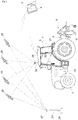
- a tractor 1 exemplified according to the present embodiment is configured to enable the autonomous travel in a field, which is an example of a work area, by using an autonomous travel system for a work vehicle.
- the autonomous travel system for a work vehicle includes an autonomous travel unit 2 mounted on the tractor 1, and a portable communication terminal 3 that has the communication settings so as to communicate with the autonomous travel unit 2.
- a notebook personal computer or a smartphone may be used for the portable communication terminal 3.
- the tractor 1 is coupled to a rotary tiller 6, which is an example of a work device, in a liftable and rotatable manner via a three-point link mechanism 5 at its rear part.
- a rotary tiller 6 which is an example of a work device
- the tractor 1 is designed to enable rotary tilling.
- the rear part of the tractor 1 may be coupled to a work device such as a plow, a seed planter, or a spraying device.
- the tractor 1 includes, for example, right and left front wheels 7 that may be driven and steered, right and left rear wheels 8 that may be driven, a cabin 9 that forms a passenger driving part, an electronically controlled diesel engine (hereinafter referred to as engine) 10 including a common rail system, an electronically controlled transmission device 11 that shifts gears for the power from the engine 10, a full hydraulic power steering mechanism 12 that steers the right and left front wheels 7, right and left parking brakes (not illustrated) that control the right and left rear wheels 8, an electronically controlled brake operation mechanism 13 that enables the hydraulic operation of the right and left parking brakes, a working clutch (not illustrated) that intermittently transmits the power to the rotary tiller 6, an electronically controlled clutch operation mechanism 14 that enables the hydraulic operation of the working clutch, an electrohydraulic controlled elevator drive mechanism 15 that drives and elevates the rotary tiller 6, a vehicle-mounted electronic control unit 16 that stores various control programs, or the like, regarding the autonomous travel, or the like, of the vehicle itself (the tractor) 1,
- engine 10 including a common rail system
- an electronically controlled gasoline engine including an electronic governor may be used as the engine 10.
- a hydromechanical variable transmission (HMT), a hydrostatic variable transmission (HST), or a belt-type variable transmission may be used as the transmission device 11.
- An electric power steering mechanism including an electric motor may be used as the power steering mechanism 12.
- the cabin 9 includes a steering wheel 20 that enables the manual steering of the right and left front wheels 7 via the power steering mechanism 12, and a seat 21 for a user.
- a speed change lever that enables the manual operation of the transmission device 11
- right and left brake pedals that enable the human operation of the right and left parking brakes
- an elevation lever that enables the manual elevation operation of the rotary tiller 6.
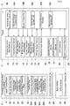
- the vehicle-mounted electronic control unit 16 includes for example, a speed change control part 16A that controls the operation of the transmission device 11, a brake control part 16B that controls the operation of the right and left parking brakes, a work device control part 16C that controls the operation of the rotary tiller 6, a nonvolatile vehicle mounted storage part 16D that stores, for example, vehicle body data including the minimum turning radius and the working width of the vehicle itself 1 and a previously generated target route P for the autonomous travel, and a steering angle setting part 16E that sets the target steering angle of the right and left front wheels 7 during the autonomous travel and outputs it to the power steering mechanism 12.
- a speed change control part 16A that controls the operation of the transmission device 11
- a brake control part 16B that controls the operation of the right and left parking brakes
- a work device control part 16C that controls the operation of the rotary tiller 6
- a nonvolatile vehicle mounted storage part 16D that stores, for example, vehicle body data including the minimum turning radius and the working width of the vehicle itself 1 and a
- the positioning unit 19 includes, for example, a satellite navigation device 22 that uses the GPS (Global Positioning System), which is an example of the global navigation satellite system (GNSS: Global Navigation Satellite System), to measure the current position and the current orientation of the vehicle itself 1, and an inertia measurement device (IMU: Inertial Measurement Unit) 23 that includes, for example, a three-axis gyroscope and a three-direction acceleration sensor to measure the attitude, the orientation, or the like, of the vehicle itself 1.
- GPS Global Positioning System
- GNSS Global Navigation Satellite System
- IMU Inertial Measurement Unit
- the positioning methods using GPS include, for example, DGPS (Differential GPS: a relative positioning method) and RTK-GPS (Real Time Kinematic GPS: an interference positioning method), and RTK-GPS suitable for the positioning of a movable object is adopted in the present embodiment. Therefore, a base station 24 that enables the positioning using RTK-GPS is provided at a known location around a field.
- DGPS Direct GPS: a relative positioning method
- RTK-GPS Real Time Kinematic GPS: an interference positioning method
- the tractor 1 and the base station 24 include, respectively, GPS antennas 26, 27 that receive radio waves transmitted from GPS satellites 25, communication modules 28, 29 that enable wireless communications of various types of data including positioning data between the tractor 1 and the base station 24, and the like.
- This allows the satellite navigation device 22 to measure the current position and the current orientation of the vehicle itself 1 with high accuracy based on the positioning data obtained when the GPS antenna 26 on the tractor side receives a radio wave from the GPS satellite 25 and the positioning data obtained when the GPS antenna 27 on the base station side receives a radio wave from the GPS satellite 25.
- the positioning unit 19 is able to measure the current position, the current orientation, and the attitude angle (the yaw angle, the roll angle, the pitch angle) of the vehicle itself 1 with high accuracy.
- the portable communication terminal 3 includes, for example, a terminal electronic control unit 30 that stores various control programs for controlling the operation of the liquid crystal panel 4, or the like, and a communication module 31 that enables wireless communications of various types of data with the communication module 28 on the tractor side.
- the terminal electronic control unit 30 includes, for example, a terminal storage part (an example of a storage part) 30A that stores, for example, vehicle body data obtained through wireless communications, or the like, with the tractor side, a positioning data acquisition part 30B that acquires positioning data through wireless communications with the tractor side, a field data acquisition part 30C that acquires the field data including the size and the shape of a field from the acquired positioning data, and a target route generation part 30D that generates the target route P for the autonomous travel.
- a terminal storage part an example of a storage part
- a positioning data acquisition part 30B that acquires positioning data through wireless communications with the tractor side
- a field data acquisition part 30C that acquires the field data including the size and the shape of a field from the acquired positioning data
- a target route generation part 30D that generates the target route P for the autonomous travel.
- the terminal electronic control unit 30 causes the liquid crystal panel 4 to display, for example, a route selection part 32 that prompts the selection of the target route P, an arbitrary data input part 33 to which arbitrary setting data for target route generation is input, a priority item selection part 34 that prompts the selection of a priority item regarding the generation of the target route P, and a generation command part 35 that gives a command to the target route generation part 30D so as to generate the target route P.
- the portable communication terminal 3 forms a target route generation system to generate the target route P for the autonomous travel of the tractor 1.
- the terminal storage part 30A stores the vehicle body data and the field data as the basic data necessary for generating the target route P.
- the arbitrary setting data input to the arbitrary data input part 33 includes, for example, work area determination points for determining a work area A in the field, an autonomous travel start point ps, an autonomous travel end point pe, a reference work direction ⁇ p, and a turning method.
- the priority items selected by the priority item selection part 34 include the maximization of a working size, the minimization of a non-working travel distance, the optimization of a circling travel route area P1 along the outer periphery of the field, and the avoidance of generation of an overlapped route area P0.
- the target route generation part 30D executes the target route generation control when the target route generation mode is selected with the touch operation on the liquid crystal panel 4.
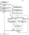
- the control operation of the target route generation part 30D during the target route generation control is described below based on the flowchart illustrated in FIG. 3 .
- the target route generation part 30D first performs a field data checking process (step #1) to check whether the terminal storage part 30A stores the corresponding field data based on the current position of the tractor 1 acquired by the positioning data acquisition part 30B in response to the selection of the target route generation mode.
- a target route checking process (step #2) is performed to check whether the terminal storage part 30A stores the corresponding target route P based on the field data and the vehicle body data stored in the terminal storage part 30A.
- the stored target route P is read from the terminal storage part 30A, the read target route P and the above-described route selection part 32 are displayed on the liquid crystal panel 4, and a stored route selection process (step #3) is performed to prompt the user to make a selection as to whether the read target route P is to be used. Then, when the use of the read target route P is selected by the user, the target route generation control is terminated.
- a field data acquisition guidance display process (step #4) is performed to cause the liquid crystal panel 4 to display the execution guidance for the field data acquisition travel so as to obtain the field data so that the user is caused to conduct the field data acquisition travel to travel in the tractor 1 along the outer periphery of the field. Furthermore, the positioning data acquisition part 30B is caused to perform a positioning data acquisition process (step #5) to acquire the positioning data measured by the positioning unit 19 of the tractor 1 during the field data acquisition travel through the wireless communications with the tractor side.
- the field data acquisition part 30C is caused to perform a field data acquisition process (step #6) to acquire the field data including the size or the shape of the field from the positioning data acquired by the positioning data acquisition part 30B.
- a field data acquisition process step #6 to acquire the field data including the size or the shape of the field from the positioning data acquired by the positioning data acquisition part 30B.
- step #7 When the corresponding target route P is not stored in the target route checking process (step #2), when the refusal of the target route P read in the stored route selection process (step #3) is selected by the user, or when the field data is acquired in the field data acquisition process (step #6), an operation screen display process (step #7) is performed to cause the liquid crystal panel 4 to display the arbitrary data input part 33, the priority item selection part 34, the generation command part 35, described above, and the like, together with the shape, or the like, of the field included in the field data.
- the user is caused to input arbitrary setting data or select a priority item with regard to the generation of the target route P.
- a first target route generation process (step #8) is performed to generate a first target route corresponding to the priority item as the target route P based on the above-described vehicle body data, the field data, and the selected priority item.
- a second target route generation process (step #9) is performed to generate, as the target route P, a second target route based on the above-described vehicle body data, the field data, and each set of input arbitrary setting data.
- the generated target route P is displayed on the liquid crystal panel 4 together with the shape of the field, the above-described route selection part 32, and the like, and a generated route selection process (step #10) is performed to cause the user to select whether the generated target route P is to be used.
- step #10 When the use of the generated target route P is selected by the user in the generated route selection process (step #10), the target route generation control is terminated.
- step #7 When the user selects the refusal of the generated target route P in the generated route selection process (step #10), the operation screen display process (step #7) is returned so that the user is again caused to input arbitrary setting data in the arbitrary data input part 33 or select a priority item in the priority item selection part 34.
- step #7 when the user performs a correction operation such as the input of corrected or added arbitrary setting data in the arbitrary data input part 33 or the additional selection of a priority item in the priority item selection part 34, and then executes a command operation in the generation command part 35, a transition is made to the target route correction process (step #11) so that the previously generated target route P is corrected based on the currently input arbitrary setting data or the currently selected priority item and then a transition is made to the generated route selection process (step #10).
- a correction operation such as the input of corrected or added arbitrary setting data in the arbitrary data input part 33 or the additional selection of a priority item in the priority item selection part 34
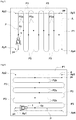
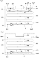
- the target route generation part 30D first automatically selects a plurality of work area determination points (four work area determination points Ap1 to Ap4 in FIG. 4 ) for determining the work area A suitable for the shape of the field (e.g., the outer periphery shape of the field indicated by a broken line in FIG. 4 ) based on the above-described vehicle body data, the field data, and the selected priority item so as to determine the work area A and then causes the liquid crystal panel 4 to display the selected work area determination points Ap1 to Ap4 and the determined work area A together with the shape of the field, or the like, so as to give a notification to the user (see FIG. 4 ).
- the work area A determined in accordance with the shape of the field is not always suitable for the generation of the target route P for the autonomous travel of the tractor 1, and there is a need to select work area determination points so as to properly simplify the work area A in accordance with the shape of the field in consideration of the working width of the tractor 1, etc. Therefore, the number of selectable work area determination points are limited to a predetermined number (e.g., 30 points) so that it is possible to determine the work area A suitable for the shape of the field while preventing excessive control loads.
- a predetermined number e.g., 30 points
- the reference work direction ⁇ p, the autonomous travel start point ps, and the autonomous travel end point pe are automatically selected in consideration of the priority items, and the like, and the selected reference work direction ⁇ p, the autonomous travel start point ps, and the autonomous travel end point pe are displayed on the liquid crystal panel 4 together with the work area A so as to give a notification to the user (see FIG. 4 ).
- the first target route is generated as the target route P corresponding to the priority item, and the generated first target route is displayed on the liquid crystal panel 4 together with the work area A, and the like, so as to give a notification to the user.
- the target route generation part 30D determines the work area A based on the arbitrarily input work area determination points Ap1 to Ap4 and causes the liquid crystal panel 4 to display the arbitrarily input work area determination points Ap 1 to Ap4 and the determined work area A together with the shape of the field, or the like, so as to give a notification to the user (see FIG. 4 ).
- the arbitrarily input reference work direction ⁇ p is displayed together with the work area A, and the like, on the liquid crystal panel 4 and is notified of the user (see FIG. 4 ).
- the arbitrarily input autonomous travel start point ps and the arbitrarily input autonomous travel end point pe are displayed together with the work area A, or the like, on the liquid crystal panel 4 and are notified of the user (see FIG. 4 ).
- the second target route is generated as the target route P based on the determined work area A and the arbitrarily input reference work direction ⁇ p, the arbitrarily input autonomous travel start point ps, and the arbitrarily input autonomous travel end point pe during the second target route generation process, and the generated second target route is displayed together with the work area A, and the like, on the liquid crystal panel 4 and is notified of the user.
- the work area determination points (the four work area determination points Ap1 to Ap4 in FIGS. 5 to 6 ) for determining the rectangular work area A that may ensure the circling travel route area (circling travel area) P1 in the interval with the outer periphery of the field are arbitrarily input
- the autonomous travel start point ps and the autonomous travel end point pe corresponding to the entrance and the exit of the field are arbitrarily input
- the reference work direction ⁇ p in a direction along the short side of the work area A is arbitrarily input
- a command is received from the generation command part 35
- the target route generation part 30D generates the second target route illustrated in FIG.
- the generated second target route is displayed together with the above-described route selection part 32, or the like, on the liquid crystal panel 4 so that the user is caused to make a selection as to whether the generated second target route is to be used.
- the second target route illustrated in FIG. 5 includes a plurality of first straight work route areas P2a that have the same length as the short side of the work area A and are arranged to be parallel at intervals of a certain distance corresponding to the working width, and a plurality of direction change route areas P3 that extend from the end point to the start point of the adjacent first straight work route areas P2a, which allows the autonomous travel of the tractor 1 from the autonomous travel start point ps to the autonomous travel end point pe that are arbitrarily input by the user.
- the target route generation part 30D generates the second target route illustrated in FIG. 6 as the target route P during the second target route generation process. Then, during the generated route selection process, the generated second target route is displayed together with the above-described route selection part 32, or the like, on the liquid crystal panel 4 so that the user is caused to make a selection as to whether the generated second target route is to be used.
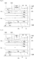
- the second target route illustrated in FIG. 6 includes a plurality of second straight work route areas P2b that have the same length as the long side of the work area A and are arranged to be parallel at intervals of a certain distance corresponding to the working width, and a plurality of direction change route areas P3 that extend from the end point to the start point of the adjacent second straight work route areas P2b so as to enable the autonomous travel of the tractor 1 from the autonomous travel start point ps to the autonomous travel end point pe that are arbitrarily input by the user.
- the target route generation part 30D automatically determines the plurality of work area determination points (the four work area determination points Ap1 to Ap4 in FIGS. 5 to 6 ), the autonomous travel start point ps, the autonomous travel end point pe, and the like, so as to obtain the rectangular work area A that may ensure the circling travel route area (circling travel area) P1 in the interval with the outer periphery of the field and generates two types of first target routes illustrated in FIGS.
- the two types of generated first target routes are displayed together with the above-described route selection part 32, or the like, on the liquid crystal panel 4 so that the user is caused to make a selection as to whether the two types of generated first target routes is to be used.
- the first target route illustrated in FIG. 5 includes the plurality of first straight work route areas P2a and the plurality of direction change route areas P3 described above so as to enable the autonomous travel of the tractor 1 from the autonomous travel start point ps to the autonomous travel end point pe determined by the target route generation part 30D.
- the first target route illustrated in FIG. 6 includes the plurality of second straight work route areas P2b and the plurality of direction change route areas P3 described above so as to enable the autonomous travel of the tractor 1 from the autonomous travel start point ps to the autonomous travel end point pe determined by the target route generation part 30D.
- the user may make a selection on the route selection part 32 as to whether the two types of first target routes are to be used as the target route P. Furthermore, in a case where one of the first target routes is selected as the target route P, after the tilling work is performed due to the autonomous travel of the tractor 1 at the work area A on the center side of the field, the width of the circling travel route area P1, which is the remaining unworked area in the neighborhood, may be the same or substantially the same as the integral multiple of the working width. Accordingly, it is easy to perform the circling work travel of the tractor 1 due to the manual drive or the autonomous travel of the tractor 1.
- the refusal of the first target routes illustrated in FIGS. 5 to 6 are selected by the route selection part 32, the corrected arbitrary setting data for switching the positions of the autonomous travel start point ps and the autonomous travel end point pe are input, and then a command operation is performed by the generation command part 35 so that, in the target route correction process by the target route generation part 30D based on the above, the first target routes may be generated in which the positions of the autonomous travel start point ps and the autonomous travel end point pe in the first target routes illustrated in FIGS. 5 to 6 have been switched.
- the target route generation part 30D when the maximization of the working size and the optimization of the circling travel route area are selected as priority items and then a command is received from the generation command part 35, the target route generation part 30D generates two types of first target routes illustrated in FIGS. 5 to 6 as the target route P during the first target route generation process. Then, during the generated route selection process, the two types of generated first target routes are displayed together with the above-described route selection part 32, and the like, on the liquid crystal panel 4 so that the user is caused to make a selection as to whether the two types of generated first target routes are to be used.
- the target route generation part 30D automatically determines the plurality of work area determination points (the four work area determination points Ap1 to Ap4 in FIGS. 5 to 6 ), the autonomous travel start point ps, the autonomous travel end point pe, the reference work direction ⁇ p, and the like, and generates the first target route illustrated in FIG.
- the generated first target route is displayed together with the above-described route selection part 32, or the like, on the liquid crystal panel 4 so that the user is caused to make a selection as to whether the generated first target route is to be used.
- the first target route illustrated in FIG. 6 includes the plurality of second straight work route areas P2b and the plurality of direction change route areas P3 described above so as to enable the autonomous travel of the tractor 1 from the autonomous travel start point ps to the autonomous travel end point pe determined by the target route generation part 30D.
- the width of the circling travel route area P1 which is the remaining unworked area in the neighborhood, may be the same or substantially the same as the integral multiple of the working width.
- the target route generation part 30D when the maximization of the working size, the minimization of the non-working travel distance, and the optimization of the circling travel route area are selected as priority items and then a command is received from the generation command part 35, the target route generation part 30D generates the first target route illustrated in FIG. 6 as the target route P during the first target route generation process. Then, during the generated route selection process, the generated first target route is displayed together with the above-described route selection part 32, and the like, on the liquid crystal panel 4 so that the user is caused to make a selection as to whether the generated first target route is to be used.
- the target route generation part 30D generates the second target route illustrated in FIG. 7 as the target route P during the second target route generation process. Then, during the generated route selection process, the generated second target route is displayed together with the above-described route selection part 32, or the like, on the liquid crystal panel 4 so that the user is caused to make a selection as to whether the generated second target route is to be used.
- the second target route illustrated in FIG. 7 includes the plurality of above-described second straight work route areas P2b, a detour work route area P4 that includes a detour route area Pa to make a detour around the projection portion 36 during the interrupted tilling work and that is adjacent to the last second straight work route area P2b, and the plurality of direction change route areas P3 that extend from the end point to the start point of the adjacent second straight work route area P2b and the detour work route area P4 so as to enable the autonomous travel of the tractor 1 from the autonomous travel start point ps to the autonomous travel end point pe that are arbitrarily input by the user.
- the route area adjacent to the detour route area Pa is an unworked area Pb that is crushed during the autonomous travel of the tractor 1 in the detour route area Pa, and therefore there is a decrease in the final working size.
- the target route generation part 30D first determines a difference in the work area caused due to the presence or absence of the detour work route area P4 illustrated in FIG. 7 during the first target route generation process.
- the plurality of work area determination points (the eight work area determination points Ap1 to Ap8 in FIG. 7 ), the autonomous travel start point ps, the autonomous travel end point pe, the reference work direction ⁇ p, and the like, are automatically determined and the first target route illustrated in FIG. 7 is generated as the target route P so as to obtain the wide and recessed work area A substantially along the outer periphery of the field enabling the generation of the detour work route area P4.
- the generated first target route is displayed together with the above-described route selection part 32, or the like, on the liquid crystal panel 4 so that the user is caused to make a selection as to whether the generated first target route is to be used.
- the plurality of work area determination points (the four work area determination points Ap1 to Ap4 in FIG. 8 ), the autonomous travel start point ps, the autonomous travel end point pe, the reference work direction ⁇ p, and the like, are automatically determined and the first target route illustrated in FIG. 8 is generated as the target route P so as to obtain the rectangular and narrow work area A in which the detour work route area P4 is not generated. Then, during the generated route selection process, the generated first target route is displayed together with the above-described route selection part 32, or the like, on the liquid crystal panel 4 so that the user is caused to make a selection as to whether the generated first target route is to be used.
- the first target route illustrated in FIG. 7 includes the plurality of second straight work route areas P2b, the detour work route area P4, and the plurality of direction change route areas P3 described above so as to enable the autonomous travel of the tractor 1 from the autonomous travel start point ps to the autonomous travel end point pe determined by the target route generation part 30D.
- the first target route illustrated in FIG. 8 includes the plurality of second straight work route areas P2b and the plurality of direction change route areas P3 as described above so as to enable the autonomous travel of the tractor 1 from the autonomous travel start point ps to the autonomous travel end point pe determined by the target route generation part 30D.
- the target route generation part 30D when the minimization of the non-working travel distance is selected as a priority item and then a command is received from the generation command part 35, the target route generation part 30D generates, as the target route P, the first target route that does not include the detour work route area P4 illustrated in FIG. 8 during the first target route generation process. Then, during the generated route selection process, the generated first target route is displayed together with the above-described route selection part 32, or the like, on the liquid crystal panel 4 so that the user is caused to make a selection as to whether the generated first target route is to be used.
- the target route generation part 30D determines, at the stage for determining the work area A, whether it is desirable to determine the recessed and wide work area A (see FIG. 7 ) requiring the detour work route area P4 or it is desirable to determine the rectangular and narrow work area A (see FIG. 8 ) eliminating the detour work route area P4, when it is desirable to determine the recessed and wide work area A, the large number of the work area determination points (the eight work area determination points Ap1 to Ap8 in FIG. 7 ) necessary for the determination are selected, and then the first target route is generated as described above. Conversely, when it is desirable to determine the rectangular and narrow work area A, the small number of the work area determination points (the four work area determination points Ap1 to Ap4 in FIG. 8 ) necessary for the determination are selected, and then the first target route is generated as described above.
- the target route generation part 30D automatically determines the plurality of work area determination points (the four work area determination points Ap1 to Ap4 in FIGS. 9 to 12 ), the autonomous travel start point ps, the autonomous travel end point pe, and the like, so as to obtain the rectangular work area A that may ensure the circling travel route area (circling travel area) P1 in the interval with the outer periphery of the field and generates the first target route, or the like, illustrated in FIG.
- the generated first target route is displayed together with the above-described route selection part 32, or the like, on the liquid crystal panel 4 so that the user is caused to make a selection as to whether the generated first target route is to be used.
- the refusal of the first target route, or the like, illustrated in FIG. 9 is selected by the route selection part 32, the reference work direction ⁇ p is determined to be in the direction along the short side of the work area A, the corrected arbitrary setting data for changing the position of the autonomous travel end point pe to the position illustrated in FIGS.
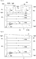
- the first target route illustrated in FIG. 10 includes the plurality of above-described first straight work route areas P2a, a detour move route area P5 that includes the detour route area Pa to make a detour around the projection portion 37 and that is adjacent to the last first straight work route area P2a, and the plurality of direction change route areas P3 that extend from the end point to the start point of the adjacent first straight work route areas P2a and the detour move route area P5 so as to enable the autonomous travel of the tractor 1 from the autonomous travel start point ps determined by the target route generation part 30D to the autonomous travel end point pe corrected and input by the user.
- the first target route illustrated in FIG. 11 includes the plurality of above-described first straight work route areas P2a, the direction change route areas P3 extending from the end point to the start point of the adjacent first straight work route areas P2a, and the circling travel route area P1 from the end point of the last first straight work route area P2a to the autonomous travel end point pe so as to enable the autonomous travel of the tractor 1 from the autonomous travel start point ps determined by the target route generation part 30D to the autonomous travel end point pe corrected and input by the user.
- the first target route illustrated in FIG. 12 includes the plurality of above-described first straight work route areas P2a, the plurality of direction change route areas P3 extending from the end point to the start point of the adjacent first straight work route areas P2a, a single return direction change route area P6 that extends from the end point of the last first straight work route area P2a to the start point of the previous first straight work route area P2a adjacent to the last first straight work route area P2a, and a move route area P7 that extends from the end point of the previous first straight work route area P2a to the autonomous travel end point pe so as to have the route setting such that the first moving travel and the second working travel are executed in the previous first straight work route area P2a and so as to enable the autonomous travel of the tractor 1 from the autonomous travel start point ps determined by the target route generation part 30D to the autonomous travel end point pe corrected and input by the user.
- the user may make a selection on the route selection part 32 as to whether three types of first target routes are to be used as the target route P during the generated route selection process by the target route generation part 30D.
- the non-working travel distance in the target route P is relatively short, and therefore it is possible to achieve a reduction in the fuel consumption, a reduction in the working time, and the like, due to a reduction in the non-working travel distance.
- the route section adjacent to the detour route area Pa is the unworked area Pb that is crushed during the autonomous travel of the tractor 1 in the detour route area Pa, and therefore there is a decrease in the final working size.
- the first target route illustrated in FIG. 11 is selected as the target route P, it is possible to conduct a work over the entire work area A, and it is possible to prevent the occurrence of the problem in that it is difficult to do a work as the route area is beaten due to the overlapped travel that is the travel multiple times on the same overlapped route area in the target route P of the tractor 1.
- the presence of the circling travel route area P1 causes an increase in the non-working travel distance on the target route P and thus an increase in the fuel consumption and an increase in the working time.
- the first target route illustrated in FIG. 12 is selected as the target route P
- the target route generation part 30D generates the second target route illustrated in FIG.
- the generated second target route is displayed together with the above-described route selection part 32, or the like, on the liquid crystal panel 4 so that the user is caused to make a selection as to whether the generated second target route is to be used.
- the refusal of the second target route illustrated in FIG. 10 is selected by the route selection part 32, the maximization of the working size is selected as a priority item for correction, and then a command operation is performed by the generation command part 35 so that, during the target route correction process by the target route generation part 30D based on the above, for example, two types of second target routes illustrated in FIGS. 11 to 12 may be generated as the second target route corrected based on the maximization of the working size.
- the route selection part 32 the maximization of the working size and the minimization of the non-working travel distance are selected as priority items for correction, and then a command operation is performed by the generation command part 35 so that, during the target route correction process by the target route generation part 30D based on the above, for example, the second target route illustrated in FIG. 12 may be generated as the second target route corrected based on the maximization of the working size and the minimization of the non-working travel distance.
- the generated second target route is displayed together with the above-described route selection part 32, or the like, on the liquid crystal panel 4 so that the user is caused to make a selection as to whether the generated second target route is to be used.
- the second target route illustrated in FIG. 13 includes above-described the plurality of second straight work route areas P2b, the two detour work route areas P4 including the common detour route area Pa to make a detour around the projection portion 38, and the plurality of direction change route areas P3 extending from the end point to the start point of the adjacent first straight work route areas P2a and the detour work route area P4 so as to enable the autonomous travel of the tractor 1 from the autonomous travel start point ps to the autonomous travel end point pe, which are arbitrarily input by the user.
- the common detour route area Pa is the overlapped route area P0 where the tractor 1 travels in an overlapped manner during the autonomous travel of the tractor 1, and therefore there is a possibility of a problem in that it is difficult to conduct a work as the detour route area Pa is beaten due to the overlapped travel of the tractor 1.
- the target route generation part 30D automatically determines the plurality of work area determination points (the eight work area determination points Ap1 to Ap8 in FIGS. 13 to 14 , the nine work area determination points Ap1 to Ap9 in FIG.
- the autonomous travel start point ps the autonomous travel end point pe, and the like, so as to obtain the recessed work area A that may ensure the circling travel route area (circling travel area) P1 in the interval with the outer periphery of the field and generates the first target route, or the like, illustrated in FIG. 13 as the target route P corresponding to the optimization of the circling travel route area P1 during the first target route generation process.
- the generated first target route is displayed together with the above-described route selection part 32, or the like, on the liquid crystal panel 4 so that the user is caused to make a selection as to whether the generated first target route is to be used.
- the route selection part 32 selects the avoidance of generation of the overlapped route area P0 as a priority item for correction, and then a command operation is performed by the generation command part 35 so that, during the target route correction process by the target route generation part 30D based on the above, for example, two types of first target routes illustrated in FIGS. 14 to 15 may be generated as the first target routes corrected based on the avoidance of generation of the overlapped route area P0.
- the target route generation part 30D selects the nine work area determination points Ap1 to Ap9, automatically divides the recessed work area A into two, a larger L-shaped first area Al and a smaller rectangular second area A2, and automatically determines the travel start points and the travel end points of the first area Al and the second area A2.
- the first target route illustrated in FIG. 14 includes above-described the plurality of second straight work route areas P2b, the two detour work route areas P4 including the detour route area Pa to make a detour around the projection portion 38, and the plurality of direction change route areas P3 extending from the end point to the start point of the adjacent first straight work route areas P2a and the detour work route area P4 so as to enable the autonomous travel of the tractor 1 from the autonomous travel start point ps to the autonomous travel end point pe determined by the target route generation part 30D. That is, the first target route illustrated in FIG. 14 includes the two detour work route areas P4 so as to eliminate the overlapped route area P0 for the overlapped travel of the tractor 1 that is generated in the first target route illustrated in FIG. 13 , thus, it is possible to prevent the problem in that it is difficult to conduct a work as the overlapped route area P0 is beaten.
- the first target route illustrated in FIG. 15 includes the plurality of above-described second straight work route areas P2b generated in the wide area of the first area Al, a plurality of third straight work route areas P2c generated in the narrow area of the first area Al with the same arrangement setting as that of the second straight work route area P2b, fourth straight work route areas P2d generated in the second area A2 with the same arrangement setting as that of the second straight work route area P2b, the plurality of direction change route areas P3 extending from the end point to the start point of the adjacent first straight work route areas P2a to the fourth straight work route areas P2d, and a single detour move route area P8 including the detour route area Pa to make a detour around the projection portion 38 and extending from the travel end point of the first area Al to the travel start point of the second area A2 so as to enable the autonomous travel of the tractor 1 from the autonomous travel start point ps to the autonomous travel end point pe determined by the target route generation part 30D.
- the first target route illustrated in FIG. 15 includes the single detour move route area P8 so as to eliminate the overlapped route area P0 for the overlapped travel of the tractor 1 that is generated in the first target route illustrated in FIG. 13 , thus, it is possible to prevent the problem in that it is difficult to conduct a work as the overlapped route area P0 is beaten.
- the second target route illustrated in FIG. 16 includes above-described the plurality of second straight work route areas P2b and the plurality of direction change route areas P3 extending from the end point to the start point of the adjacent second straight work route areas P2b so as to enable the autonomous travel of the tractor 1 from the autonomous travel start point ps to the autonomous travel end point pe that are arbitrarily input by the user.
- the target route generation part 30D automatically determines the plurality of work area determination points (the four work area determination points Ap1 to Ap4 in FIG. 17 ), the autonomous travel end point pe, the working width, and the like, so as to obtain the trapezoidal work area A that may ensure the circling travel route area (circling travel area) P1 in the interval with the outer periphery of the field and generates the first target route illustrated in FIG. 17 as the target route P during the first target route generation process.
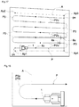
- the first target route illustrated in FIG. 17 includes the plurality of above-described second straight work route areas P2b and the plurality of direction change route areas P3 extending from the end point to the start point of the adjacent second straight work route areas P2b so as to enable the autonomous travel of the tractor 1 from the autonomous travel start point ps to the autonomous travel end point pe determined by the target route generation part 30D.
- the plurality of second straight work route areas P2b in the first target route illustrated in FIG. 17 are set such that the direction of each of the second straight work route areas P2b has a different adjustment angle ⁇ a with respect to the reference work direction ⁇ p based on the trapezoidal shape of the work area A so that the overlap degree of the working width gradually changes in accordance with the trapezoidal work area A during the autonomous travel of the tractor 1 in the second straight work route area P2b.
- the width of the circling travel route area P1 which is the remaining unworked area in the neighborhood, may be the same or substantially the same as the integral multiple of the working width. Accordingly, it is easy to perform the circling work travel of the tractor 1 due to the manual drive or the autonomous travel of the tractor 1.
- the target route generation part 30D first determines whether the use of the switchback turning is appropriate based on the minimum turning radius of the tractor 1 and the working width included in the vehicle body data during the target route correction process. Then, when the use of the switchback turning is appropriate, the arbitrarily input switchback turning is applied, and the second direction change route area P3b for the switchback turning illustrated in FIG. 19 is generated as the above-described direction change route area P3.
- the turning method is change from the arbitrarily input switchback turning to the U-shaped turning, and a first direction change route area P3a for the U-shaped turning illustrated in FIG. 18 is generated as the above-described direction change route area P3.
- a non-working area A3 that includes a switchback route area Pc, which is longer than the working width, and that needs to be provided near the dike in the field to apply the switchback turning, and thus it is possible to achieve the maximization of the working size.
- the target route generation part 30D when the plurality of target routes P are generated, the target route generation part 30D performs a calculation process to calculate a difference in the working size, the non-working travel distance, and the like, based on the target routes P and performs a difference display process to cause the liquid crystal panel 4 to display the difference in the working size, the non-working travel distance, and the like, obtained during the calculation process together with the generated target routes P and give a notification to the user.
- the target route generation part 30D stores the generated target route P in the terminal storage part 30A as the route data associated with the vehicle body data, the field data, and the like.
- the target route generation part 30D may perform the above-described field data checking process based on the current position of the tractor 1 acquired by the positioning data acquisition part 30B and the above-described target route checking process based on the field data and the vehicle body data.
- the target route generation part 30D when it is not possible to generate the target route P based on the arbitrary setting data, which is input in accordance with the user's operation during the operation screen display process, as the arbitrary setting data is inappropriate, the target route generation part 30D performs an error display process to cause the liquid crystal panel 4 to display the impossibility of the generation of the target route P and the cause thereof so as to give a notification to the user and performs a solution display process to cause the liquid crystal panel 4 to display the solution so as to suggest it to the user.
- the liquid crystal panel 4 is caused to display error messages such as "target route generation error” and "no target route has been generated as the work area is too narrow” during the error display process so as to give a notification to the user. Then, during a solution display process, the liquid crystal panel 4 is caused to display the shape of the target field for a work, the work area A that is appropriate for the shape of the field, the message for checking the setting change to the appropriate work area A, and the like, so as to give a notification to the user.
- error messages such as "target route generation error” and "no target route has been generated as the work area is too narrow” during the error display process so as to give a notification to the user.
- the liquid crystal panel 4 is caused to display the shape of the target field for a work, the work area A that is appropriate for the shape of the field, the message for checking the setting change to the appropriate work area A, and the like, so as to give a notification to the user.
- the liquid crystal panel 4 is caused to display error messages such as "target route generation error” and "no target route has been generated as the work area is too complicated” during the error display process so as to give a notification to the user. Then, during a solution display process, the liquid crystal panel 4 is caused to display the shape of the target field for a work, the work area A that is appropriately simplified with regard to the shape of the field, the message for checking the setting change to the simplified work area A, and the like, so as to give a notification to the user.
- error messages such as "target route generation error” and "no target route has been generated as the work area is too complicated” during the error display process so as to give a notification to the user.
- the liquid crystal panel 4 is caused to display the shape of the target field for a work, the work area A that is appropriately simplified with regard to the shape of the field, the message for checking the setting change to the simplified work area A, and the like, so as to give a notification to the user.
- the liquid crystal panel 4 is caused to display error messages such as "target route generation error” and "no target route has been generated as the reference work direction is not appropriate” during the error display process so as to give a notification to the user. Then, during the solution display process, the liquid crystal panel 4 is caused to display the shape of the target field for a work, the reference work direction ⁇ p that is appropriate with regard to the shape of the field, the message for checking the setting change to the appropriate reference work direction ⁇ p, and the like, so as to give a notification to the user.
- the user may select the normal operation for arbitrarily inputting all the arbitrary setting data necessary for generating the target route P with the arbitrary data input part 33 and the simple operation for performing the operation to select the priority item according to his/her own sense of value with the priority item selection part 34.
- the user may perform the normal operation so as to obtain the target route P (the second target route) based on his/her own sense of value, etc.
- the user may perform the simple operation so as to easily obtain the target route P (the first target route) suitable for his/her sense of value, etc.
- the user performs a correction operation to eliminate his/her dissatisfaction, for example, inputs corrected or added arbitrary setting data with the arbitrary data input part 33 or selects an additional priority item with the priority item selection part 34, so as to obtain the target route P in which the dissatisfaction is eliminated.
- the present invention is applicable to a target route generation system for a work vehicle that generates a target route for the autonomous travel of a passenger work vehicle such as a tractor, a passenger rice planter, a combine, a passenger mower, a wheel loader, or a snowplow, and an unmanned work vehicle such as an unmanned mower, which are configured to enable the autonomous travel.
- a passenger work vehicle such as a tractor, a passenger rice planter, a combine, a passenger mower, a wheel loader, or a snowplow
- an unmanned work vehicle such as an unmanned mower
Landscapes
- Engineering & Computer Science (AREA)
- Radar, Positioning & Navigation (AREA)
- Remote Sensing (AREA)
- Automation & Control Theory (AREA)
- Physics & Mathematics (AREA)
- General Physics & Mathematics (AREA)
- Aviation & Aerospace Engineering (AREA)
- Life Sciences & Earth Sciences (AREA)
- Soil Sciences (AREA)
- Environmental Sciences (AREA)
- Mechanical Engineering (AREA)
- Control Of Position, Course, Altitude, Or Attitude Of Moving Bodies (AREA)
- Guiding Agricultural Machines (AREA)
Applications Claiming Priority (2)
| Application Number | Priority Date | Filing Date | Title |
|---|---|---|---|
| JP2017234512A JP7027142B2 (ja) | 2017-12-06 | 2017-12-06 | 作業車両用の目標経路生成システム |
| PCT/JP2018/038142 WO2019111535A1 (fr) | 2017-12-06 | 2018-10-12 | Système de génération d'itinéraire cible pour véhicule de travail |
Publications (3)
| Publication Number | Publication Date |
|---|---|
| EP3722905A1 true EP3722905A1 (fr) | 2020-10-14 |
| EP3722905A4 EP3722905A4 (fr) | 2021-05-26 |
| EP3722905B1 EP3722905B1 (fr) | 2024-04-10 |
Family
ID=66751408
Family Applications (1)
| Application Number | Title | Priority Date | Filing Date |
|---|---|---|---|
| EP18886134.8A Active EP3722905B1 (fr) | 2017-12-06 | 2018-10-12 | Système de génération d'itinéraire cible pour véhicule de travail |
Country Status (6)
| Country | Link |
|---|---|
| US (3) | US11314261B2 (fr) |
| EP (1) | EP3722905B1 (fr) |
| JP (1) | JP7027142B2 (fr) |
| KR (3) | KR20240173642A (fr) |
| CN (4) | CN120010485A (fr) |
| WO (1) | WO2019111535A1 (fr) |
Cited By (2)
| Publication number | Priority date | Publication date | Assignee | Title |
|---|---|---|---|---|
| EP4231111A3 (fr) * | 2022-02-17 | 2023-09-20 | Yanmar Holdings Co., Ltd. | Procédé de déplacement automatique, véhicule de travail et système de déplacement automatique |
| EP4233503A4 (fr) * | 2020-10-21 | 2024-08-07 | Yanmar Holdings Co., Ltd. | Système de déplacement autonome, procédé de déplacement autonome et programme de déplacement autonome |
Families Citing this family (20)
| Publication number | Priority date | Publication date | Assignee | Title |
|---|---|---|---|---|
| JP7034866B2 (ja) * | 2018-08-20 | 2022-03-14 | 株式会社クボタ | 収穫機 |
| WO2020105275A1 (fr) * | 2018-11-19 | 2020-05-28 | 株式会社クボタ | Dispositif d'aide au déplacement pour engin de chantier, et engin de chantier |
| CN110286670A (zh) * | 2019-04-09 | 2019-09-27 | 丰疆智能科技股份有限公司 | 多台自动收割机的行驶路径规划系统及其方法 |
| JP7229119B2 (ja) * | 2019-07-29 | 2023-02-27 | ヤンマーパワーテクノロジー株式会社 | 自動走行システム |
| JP7155097B2 (ja) * | 2019-11-29 | 2022-10-18 | 株式会社クボタ | 自動走行制御システム、及び、コンバイン |
| JP7191001B2 (ja) * | 2019-11-29 | 2022-12-16 | 株式会社クボタ | 自動走行システム |
| JP7473360B2 (ja) * | 2020-02-27 | 2024-04-23 | 三菱マヒンドラ農機株式会社 | 自動制御装置 |
| JP7349147B2 (ja) * | 2020-03-31 | 2023-09-22 | 国立研究開発法人農業・食品産業技術総合研究機構 | 圃場作業車両の走行経路設定装置、走行経路設定方法および走行経路設定用プログラム |
| CN115552497B (zh) | 2020-05-28 | 2025-03-25 | 川崎摩托株式会社 | 多用途车 |
| US12078996B2 (en) * | 2020-06-30 | 2024-09-03 | Cnh Industrial America Llc | System and method for implementing end-of-row turns for agricultural machines |
| JP7622071B2 (ja) * | 2020-08-20 | 2025-01-27 | 株式会社クボタ | 作業機 |
| JP2023164760A (ja) * | 2020-09-23 | 2023-11-13 | 村田機械株式会社 | 自律走行経路計画方法 |
| JP7461849B2 (ja) * | 2020-10-06 | 2024-04-04 | ヤンマーホールディングス株式会社 | 自律走行システム、自律走行方法、及び自律走行プログラム |
| US12060120B2 (en) * | 2020-10-30 | 2024-08-13 | Dana Belgium N.V. | Vehicle steering system |
| JP7511491B2 (ja) * | 2021-01-05 | 2024-07-05 | 株式会社クボタ | 自動走行システム及び自動走行方法 |
| JP7466201B2 (ja) * | 2021-02-19 | 2024-04-12 | 国立研究開発法人農業・食品産業技術総合研究機構 | 圃場作業車両の走行経路設定装置、走行経路設定方法および走行経路設定用プログラム |
| JP7641205B2 (ja) * | 2021-09-02 | 2025-03-06 | ヤンマーホールディングス株式会社 | 自動走行方法、自動走行システム、及び自動走行プログラム |
| JP2023127875A (ja) * | 2022-03-02 | 2023-09-14 | ヤンマーホールディングス株式会社 | 自動走行方法、自動走行システム、及び自動走行プログラム |
| JP7711026B2 (ja) * | 2022-03-31 | 2025-07-22 | ヤンマーホールディングス株式会社 | 経路生成方法、経路生成システム、及び経路生成プログラム |
| JP7771043B2 (ja) * | 2022-12-23 | 2025-11-17 | 株式会社クボタ | 農作業支援装置、農作業支援システム、農業機械、走行ライン作成方法 |
Family Cites Families (26)
| Publication number | Priority date | Publication date | Assignee | Title |
|---|---|---|---|---|
| DE19629618A1 (de) * | 1996-07-23 | 1998-01-29 | Claas Ohg | Routenplanungssystem für landwirtschaftliche Arbeitsfahrzeuge |
| KR100541522B1 (ko) * | 2003-01-27 | 2006-01-10 | 에스케이 텔레콤주식회사 | 옵션 설정 기능을 갖는 네비게이션 시스템 |
| US6907336B2 (en) * | 2003-03-31 | 2005-06-14 | Deere & Company | Method and system for efficiently traversing an area with a work vehicle |
| US8407157B2 (en) * | 2003-12-22 | 2013-03-26 | Deere & Company | Locating harvested material within a work area |
| DE102004027242A1 (de) * | 2004-06-03 | 2005-12-22 | Claas Selbstfahrende Erntemaschinen Gmbh | Routenplanungssystem für landwirtschaftliche Arbeitsmaschinen |
| JP4609886B2 (ja) * | 2005-02-22 | 2011-01-12 | アルパイン株式会社 | ナビゲーション装置 |
| US8060299B2 (en) * | 2007-02-28 | 2011-11-15 | Caterpillar Inc. | Machine with automated steering system |
| KR100913670B1 (ko) * | 2007-04-27 | 2009-08-26 | 팅크웨어(주) | 네비게이션 시스템 및 네비게이션 경로 설정 방법 |
| JP5324286B2 (ja) * | 2009-03-30 | 2013-10-23 | 株式会社国際電気通信基礎技術研究所 | ネットワークロボットシステム、ロボット制御装置、ロボット制御方法およびロボット制御プログラム |
| CN102167038B (zh) * | 2010-12-03 | 2013-09-04 | 北京农业信息技术研究中心 | 农田地块全区域覆盖最优作业路径生成方法及装置 |
| JP2012185086A (ja) * | 2011-03-07 | 2012-09-27 | Jvc Kenwood Corp | ナビゲーション装置、ナビゲーション方法、およびプログラム |
| BR102015010729A2 (pt) * | 2014-05-11 | 2015-11-17 | Autonomous Solutions Inc | sistema de controle de missão e método para um sistema agrícola |
| JP6267626B2 (ja) * | 2014-11-13 | 2018-01-24 | ヤンマー株式会社 | 走行経路設定装置 |
| DE112015005974T5 (de) * | 2015-01-16 | 2017-10-12 | Mitsubishi Electric Corporation | Fahrplanungsvorrichtung und Fahrplanungsverfahren |
| JP6269534B2 (ja) * | 2015-03-02 | 2018-01-31 | トヨタ自動車株式会社 | 走行制御装置 |
| FR3042943B1 (fr) * | 2015-11-03 | 2017-11-10 | Kuhn Sa | Attelage agricole avec un systeme de gestion et de guidage de manœuvres et procede mis en œuvre par cet attelage |
| BR102016024151B1 (pt) * | 2016-01-06 | 2021-10-13 | Cnh Industrial America Llc | Meio legível por computador não transitório tangível, sistema e método para controlar pelo menos um veículo agrícola autônomo |
| JP2017127290A (ja) * | 2016-01-22 | 2017-07-27 | ヤンマー株式会社 | 農業用作業車両 |
| JP2017156874A (ja) * | 2016-02-29 | 2017-09-07 | トヨタ自動車株式会社 | 自動運転システム |
| JP6531055B2 (ja) * | 2016-03-24 | 2019-06-12 | ヤンマー株式会社 | 経路生成装置 |
| JP6437479B2 (ja) | 2016-03-22 | 2018-12-12 | ヤンマー株式会社 | 経路生成装置 |
| US10368475B2 (en) * | 2016-04-19 | 2019-08-06 | CropZilla Software, Inc. | Machine guidance for optimal working direction of travel |
| CN106662878A (zh) * | 2016-04-28 | 2017-05-10 | 株式会社小松制作所 | 作业机械的管理装置 |
| KR102360154B1 (ko) * | 2016-05-17 | 2022-02-09 | 현대자동차주식회사 | 사용자 설정을 고려한 자율 주행 제어 장치 및 방법 |
| JP6688197B2 (ja) * | 2016-09-09 | 2020-04-28 | ヤンマー株式会社 | 自律走行システム |
| US11320279B2 (en) * | 2016-12-02 | 2022-05-03 | Kubota Corporation | Travel route management system and travel route determination device |
-
2017
- 2017-12-06 JP JP2017234512A patent/JP7027142B2/ja active Active
-
2018
- 2018-10-12 KR KR1020247040061A patent/KR20240173642A/ko active Pending
- 2018-10-12 KR KR1020207005869A patent/KR102740109B1/ko active Active
- 2018-10-12 EP EP18886134.8A patent/EP3722905B1/fr active Active
- 2018-10-12 CN CN202510135745.7A patent/CN120010485A/zh active Pending
- 2018-10-12 CN CN202510135743.8A patent/CN120010484A/zh active Pending
- 2018-10-12 CN CN202510135746.1A patent/CN120010486A/zh active Pending
- 2018-10-12 WO PCT/JP2018/038142 patent/WO2019111535A1/fr not_active Ceased
- 2018-10-12 CN CN201880079167.8A patent/CN111448530B/zh active Active
- 2018-10-12 KR KR1020247040060A patent/KR20240173641A/ko active Pending
- 2018-10-12 US US16/766,664 patent/US11314261B2/en active Active
-
2022
- 2022-03-29 US US17/707,894 patent/US11662734B2/en active Active
-
2023
- 2023-04-24 US US18/138,129 patent/US12147237B2/en active Active
Cited By (3)
| Publication number | Priority date | Publication date | Assignee | Title |
|---|---|---|---|---|
| EP4233503A4 (fr) * | 2020-10-21 | 2024-08-07 | Yanmar Holdings Co., Ltd. | Système de déplacement autonome, procédé de déplacement autonome et programme de déplacement autonome |
| US12429874B2 (en) | 2020-10-21 | 2025-09-30 | Yanmar Holdings Co., Ltd. | Autonomous travel system, autonomous travel method, and autonomous travel program |
| EP4231111A3 (fr) * | 2022-02-17 | 2023-09-20 | Yanmar Holdings Co., Ltd. | Procédé de déplacement automatique, véhicule de travail et système de déplacement automatique |
Also Published As
| Publication number | Publication date |
|---|---|
| CN120010484A (zh) | 2025-05-16 |
| WO2019111535A1 (fr) | 2019-06-13 |
| KR20200088268A (ko) | 2020-07-22 |
| KR20240173642A (ko) | 2024-12-12 |
| KR102740109B1 (ko) | 2024-12-06 |
| JP7027142B2 (ja) | 2022-03-01 |
| US20200363811A1 (en) | 2020-11-19 |
| EP3722905A4 (fr) | 2021-05-26 |
| EP3722905B1 (fr) | 2024-04-10 |
| US11314261B2 (en) | 2022-04-26 |
| US20220221874A1 (en) | 2022-07-14 |
| CN120010486A (zh) | 2025-05-16 |
| US11662734B2 (en) | 2023-05-30 |
| US12147237B2 (en) | 2024-11-19 |
| CN111448530A (zh) | 2020-07-24 |
| JP2019101932A (ja) | 2019-06-24 |
| CN120010485A (zh) | 2025-05-16 |
| CN111448530B (zh) | 2025-03-07 |
| KR20240173641A (ko) | 2024-12-12 |
| US20230259136A1 (en) | 2023-08-17 |
Similar Documents
| Publication | Publication Date | Title |
|---|---|---|
| US12147237B2 (en) | Target route generation system for work vehicle | |
| JP7128328B2 (ja) | 走行経路設定装置 | |
| US11675352B2 (en) | Travel route determination system | |
| US20210080972A1 (en) | Positioning detection device and working machine having positioning detection device | |
| WO2020235470A1 (fr) | Système de déplacement automatique | |
| JP7184971B2 (ja) | 作業車両用の自動走行システム | |
| JP2019053470A (ja) | 作業車両用の自律走行システム | |
| JP7094833B2 (ja) | 走行経路表示装置 | |
| JP2019053471A (ja) | 作業車両用の自律走行システム | |
| JP7559152B2 (ja) | 作業車両用の目標経路生成システム及び作業車両用の目標経路生成方法 | |
| JP2020030644A (ja) | 自動走行システム |
Legal Events
| Date | Code | Title | Description |
|---|---|---|---|
| STAA | Information on the status of an ep patent application or granted ep patent |
Free format text: STATUS: THE INTERNATIONAL PUBLICATION HAS BEEN MADE |
|
| PUAI | Public reference made under article 153(3) epc to a published international application that has entered the european phase |
Free format text: ORIGINAL CODE: 0009012 |
|
| STAA | Information on the status of an ep patent application or granted ep patent |
Free format text: STATUS: REQUEST FOR EXAMINATION WAS MADE |
|
| 17P | Request for examination filed |
Effective date: 20200630 |
|
| AK | Designated contracting states |
Kind code of ref document: A1 Designated state(s): AL AT BE BG CH CY CZ DE DK EE ES FI FR GB GR HR HU IE IS IT LI LT LU LV MC MK MT NL NO PL PT RO RS SE SI SK SM TR |
|
| AX | Request for extension of the european patent |
Extension state: BA ME |
|
| DAV | Request for validation of the european patent (deleted) | ||
| DAX | Request for extension of the european patent (deleted) | ||
| A4 | Supplementary search report drawn up and despatched |
Effective date: 20210426 |
|
| RIC1 | Information provided on ipc code assigned before grant |
Ipc: G05D 1/02 20200101AFI20210420BHEP Ipc: A01B 69/00 20060101ALI20210420BHEP |
|
| STAA | Information on the status of an ep patent application or granted ep patent |
Free format text: STATUS: EXAMINATION IS IN PROGRESS |
|
| 17Q | First examination report despatched |
Effective date: 20220302 |
|
| GRAP | Despatch of communication of intention to grant a patent |
Free format text: ORIGINAL CODE: EPIDOSNIGR1 |
|
| STAA | Information on the status of an ep patent application or granted ep patent |
Free format text: STATUS: GRANT OF PATENT IS INTENDED |
|
| INTG | Intention to grant announced |
Effective date: 20231115 |
|
| GRAS | Grant fee paid |
Free format text: ORIGINAL CODE: EPIDOSNIGR3 |
|
| GRAA | (expected) grant |
Free format text: ORIGINAL CODE: 0009210 |
|
| STAA | Information on the status of an ep patent application or granted ep patent |
Free format text: STATUS: THE PATENT HAS BEEN GRANTED |
|
| AK | Designated contracting states |
Kind code of ref document: B1 Designated state(s): AL AT BE BG CH CY CZ DE DK EE ES FI FR GB GR HR HU IE IS IT LI LT LU LV MC MK MT NL NO PL PT RO RS SE SI SK SM TR |
|
| REG | Reference to a national code |
Ref country code: GB Ref legal event code: FG4D |
|
| REG | Reference to a national code |
Ref country code: CH Ref legal event code: EP |
|
| REG | Reference to a national code |
Ref country code: DE Ref legal event code: R096 Ref document number: 602018068030 Country of ref document: DE |
|
| REG | Reference to a national code |
Ref country code: IE Ref legal event code: FG4D |
|
| REG | Reference to a national code |
Ref country code: LT Ref legal event code: MG9D |
|
| REG | Reference to a national code |
Ref country code: NL Ref legal event code: MP Effective date: 20240410 |
|
| REG | Reference to a national code |
Ref country code: AT Ref legal event code: MK05 Ref document number: 1675547 Country of ref document: AT Kind code of ref document: T Effective date: 20240410 |
|
| PG25 | Lapsed in a contracting state [announced via postgrant information from national office to epo] |
Ref country code: NL Free format text: LAPSE BECAUSE OF FAILURE TO SUBMIT A TRANSLATION OF THE DESCRIPTION OR TO PAY THE FEE WITHIN THE PRESCRIBED TIME-LIMIT Effective date: 20240410 |
|
| PG25 | Lapsed in a contracting state [announced via postgrant information from national office to epo] |
Ref country code: NL Free format text: LAPSE BECAUSE OF FAILURE TO SUBMIT A TRANSLATION OF THE DESCRIPTION OR TO PAY THE FEE WITHIN THE PRESCRIBED TIME-LIMIT Effective date: 20240410 |
|
| PG25 | Lapsed in a contracting state [announced via postgrant information from national office to epo] |
Ref country code: IS Free format text: LAPSE BECAUSE OF FAILURE TO SUBMIT A TRANSLATION OF THE DESCRIPTION OR TO PAY THE FEE WITHIN THE PRESCRIBED TIME-LIMIT Effective date: 20240810 |
|
| PG25 | Lapsed in a contracting state [announced via postgrant information from national office to epo] |
Ref country code: BG Free format text: LAPSE BECAUSE OF FAILURE TO SUBMIT A TRANSLATION OF THE DESCRIPTION OR TO PAY THE FEE WITHIN THE PRESCRIBED TIME-LIMIT Effective date: 20240410 |
|
| PG25 | Lapsed in a contracting state [announced via postgrant information from national office to epo] |
Ref country code: FI Free format text: LAPSE BECAUSE OF FAILURE TO SUBMIT A TRANSLATION OF THE DESCRIPTION OR TO PAY THE FEE WITHIN THE PRESCRIBED TIME-LIMIT Effective date: 20240410 Ref country code: HR Free format text: LAPSE BECAUSE OF FAILURE TO SUBMIT A TRANSLATION OF THE DESCRIPTION OR TO PAY THE FEE WITHIN THE PRESCRIBED TIME-LIMIT Effective date: 20240410 |
|
| PG25 | Lapsed in a contracting state [announced via postgrant information from national office to epo] |
Ref country code: GR Free format text: LAPSE BECAUSE OF FAILURE TO SUBMIT A TRANSLATION OF THE DESCRIPTION OR TO PAY THE FEE WITHIN THE PRESCRIBED TIME-LIMIT Effective date: 20240711 |
|
| PG25 | Lapsed in a contracting state [announced via postgrant information from national office to epo] |
Ref country code: PT Free format text: LAPSE BECAUSE OF FAILURE TO SUBMIT A TRANSLATION OF THE DESCRIPTION OR TO PAY THE FEE WITHIN THE PRESCRIBED TIME-LIMIT Effective date: 20240812 |
|
| PG25 | Lapsed in a contracting state [announced via postgrant information from national office to epo] |
Ref country code: ES Free format text: LAPSE BECAUSE OF FAILURE TO SUBMIT A TRANSLATION OF THE DESCRIPTION OR TO PAY THE FEE WITHIN THE PRESCRIBED TIME-LIMIT Effective date: 20240410 |
|
| PG25 | Lapsed in a contracting state [announced via postgrant information from national office to epo] |
Ref country code: AT Free format text: LAPSE BECAUSE OF FAILURE TO SUBMIT A TRANSLATION OF THE DESCRIPTION OR TO PAY THE FEE WITHIN THE PRESCRIBED TIME-LIMIT Effective date: 20240410 |
|
| PG25 | Lapsed in a contracting state [announced via postgrant information from national office to epo] |
Ref country code: PL Free format text: LAPSE BECAUSE OF FAILURE TO SUBMIT A TRANSLATION OF THE DESCRIPTION OR TO PAY THE FEE WITHIN THE PRESCRIBED TIME-LIMIT Effective date: 20240410 |
|
| PG25 | Lapsed in a contracting state [announced via postgrant information from national office to epo] |
Ref country code: LV Free format text: LAPSE BECAUSE OF FAILURE TO SUBMIT A TRANSLATION OF THE DESCRIPTION OR TO PAY THE FEE WITHIN THE PRESCRIBED TIME-LIMIT Effective date: 20240410 |
|
| PG25 | Lapsed in a contracting state [announced via postgrant information from national office to epo] |
Ref country code: PT Free format text: LAPSE BECAUSE OF FAILURE TO SUBMIT A TRANSLATION OF THE DESCRIPTION OR TO PAY THE FEE WITHIN THE PRESCRIBED TIME-LIMIT Effective date: 20240812 Ref country code: PL Free format text: LAPSE BECAUSE OF FAILURE TO SUBMIT A TRANSLATION OF THE DESCRIPTION OR TO PAY THE FEE WITHIN THE PRESCRIBED TIME-LIMIT Effective date: 20240410 Ref country code: NO Free format text: LAPSE BECAUSE OF FAILURE TO SUBMIT A TRANSLATION OF THE DESCRIPTION OR TO PAY THE FEE WITHIN THE PRESCRIBED TIME-LIMIT Effective date: 20240710 Ref country code: LV Free format text: LAPSE BECAUSE OF FAILURE TO SUBMIT A TRANSLATION OF THE DESCRIPTION OR TO PAY THE FEE WITHIN THE PRESCRIBED TIME-LIMIT Effective date: 20240410 Ref country code: IS Free format text: LAPSE BECAUSE OF FAILURE TO SUBMIT A TRANSLATION OF THE DESCRIPTION OR TO PAY THE FEE WITHIN THE PRESCRIBED TIME-LIMIT Effective date: 20240810 Ref country code: HR Free format text: LAPSE BECAUSE OF FAILURE TO SUBMIT A TRANSLATION OF THE DESCRIPTION OR TO PAY THE FEE WITHIN THE PRESCRIBED TIME-LIMIT Effective date: 20240410 Ref country code: GR Free format text: LAPSE BECAUSE OF FAILURE TO SUBMIT A TRANSLATION OF THE DESCRIPTION OR TO PAY THE FEE WITHIN THE PRESCRIBED TIME-LIMIT Effective date: 20240711 Ref country code: FI Free format text: LAPSE BECAUSE OF FAILURE TO SUBMIT A TRANSLATION OF THE DESCRIPTION OR TO PAY THE FEE WITHIN THE PRESCRIBED TIME-LIMIT Effective date: 20240410 Ref country code: ES Free format text: LAPSE BECAUSE OF FAILURE TO SUBMIT A TRANSLATION OF THE DESCRIPTION OR TO PAY THE FEE WITHIN THE PRESCRIBED TIME-LIMIT Effective date: 20240410 Ref country code: BG Free format text: LAPSE BECAUSE OF FAILURE TO SUBMIT A TRANSLATION OF THE DESCRIPTION OR TO PAY THE FEE WITHIN THE PRESCRIBED TIME-LIMIT Effective date: 20240410 Ref country code: AT Free format text: LAPSE BECAUSE OF FAILURE TO SUBMIT A TRANSLATION OF THE DESCRIPTION OR TO PAY THE FEE WITHIN THE PRESCRIBED TIME-LIMIT Effective date: 20240410 Ref country code: RS Free format text: LAPSE BECAUSE OF FAILURE TO SUBMIT A TRANSLATION OF THE DESCRIPTION OR TO PAY THE FEE WITHIN THE PRESCRIBED TIME-LIMIT Effective date: 20240710 |
|
| REG | Reference to a national code |
Ref country code: DE Ref legal event code: R097 Ref document number: 602018068030 Country of ref document: DE |
|
| PG25 | Lapsed in a contracting state [announced via postgrant information from national office to epo] |
Ref country code: DK Free format text: LAPSE BECAUSE OF FAILURE TO SUBMIT A TRANSLATION OF THE DESCRIPTION OR TO PAY THE FEE WITHIN THE PRESCRIBED TIME-LIMIT Effective date: 20240410 |
|
| PG25 | Lapsed in a contracting state [announced via postgrant information from national office to epo] |
Ref country code: EE Free format text: LAPSE BECAUSE OF FAILURE TO SUBMIT A TRANSLATION OF THE DESCRIPTION OR TO PAY THE FEE WITHIN THE PRESCRIBED TIME-LIMIT Effective date: 20240410 |
|
| PG25 | Lapsed in a contracting state [announced via postgrant information from national office to epo] |
Ref country code: CZ Free format text: LAPSE BECAUSE OF FAILURE TO SUBMIT A TRANSLATION OF THE DESCRIPTION OR TO PAY THE FEE WITHIN THE PRESCRIBED TIME-LIMIT Effective date: 20240410 |
|
| PG25 | Lapsed in a contracting state [announced via postgrant information from national office to epo] |
Ref country code: SK Free format text: LAPSE BECAUSE OF FAILURE TO SUBMIT A TRANSLATION OF THE DESCRIPTION OR TO PAY THE FEE WITHIN THE PRESCRIBED TIME-LIMIT Effective date: 20240410 Ref country code: RO Free format text: LAPSE BECAUSE OF FAILURE TO SUBMIT A TRANSLATION OF THE DESCRIPTION OR TO PAY THE FEE WITHIN THE PRESCRIBED TIME-LIMIT Effective date: 20240410 |
|
| PG25 | Lapsed in a contracting state [announced via postgrant information from national office to epo] |
Ref country code: SM Free format text: LAPSE BECAUSE OF FAILURE TO SUBMIT A TRANSLATION OF THE DESCRIPTION OR TO PAY THE FEE WITHIN THE PRESCRIBED TIME-LIMIT Effective date: 20240410 |
|
| PG25 | Lapsed in a contracting state [announced via postgrant information from national office to epo] |
Ref country code: SM Free format text: LAPSE BECAUSE OF FAILURE TO SUBMIT A TRANSLATION OF THE DESCRIPTION OR TO PAY THE FEE WITHIN THE PRESCRIBED TIME-LIMIT Effective date: 20240410 Ref country code: SK Free format text: LAPSE BECAUSE OF FAILURE TO SUBMIT A TRANSLATION OF THE DESCRIPTION OR TO PAY THE FEE WITHIN THE PRESCRIBED TIME-LIMIT Effective date: 20240410 Ref country code: RO Free format text: LAPSE BECAUSE OF FAILURE TO SUBMIT A TRANSLATION OF THE DESCRIPTION OR TO PAY THE FEE WITHIN THE PRESCRIBED TIME-LIMIT Effective date: 20240410 Ref country code: EE Free format text: LAPSE BECAUSE OF FAILURE TO SUBMIT A TRANSLATION OF THE DESCRIPTION OR TO PAY THE FEE WITHIN THE PRESCRIBED TIME-LIMIT Effective date: 20240410 Ref country code: DK Free format text: LAPSE BECAUSE OF FAILURE TO SUBMIT A TRANSLATION OF THE DESCRIPTION OR TO PAY THE FEE WITHIN THE PRESCRIBED TIME-LIMIT Effective date: 20240410 Ref country code: CZ Free format text: LAPSE BECAUSE OF FAILURE TO SUBMIT A TRANSLATION OF THE DESCRIPTION OR TO PAY THE FEE WITHIN THE PRESCRIBED TIME-LIMIT Effective date: 20240410 |
|
| PG25 | Lapsed in a contracting state [announced via postgrant information from national office to epo] |
Ref country code: IT Free format text: LAPSE BECAUSE OF FAILURE TO SUBMIT A TRANSLATION OF THE DESCRIPTION OR TO PAY THE FEE WITHIN THE PRESCRIBED TIME-LIMIT Effective date: 20240410 |
|
| PLBE | No opposition filed within time limit |
Free format text: ORIGINAL CODE: 0009261 |
|
| STAA | Information on the status of an ep patent application or granted ep patent |
Free format text: STATUS: NO OPPOSITION FILED WITHIN TIME LIMIT |
|
| 26N | No opposition filed |
Effective date: 20250113 |
|
| PG25 | Lapsed in a contracting state [announced via postgrant information from national office to epo] |
Ref country code: SI Free format text: LAPSE BECAUSE OF FAILURE TO SUBMIT A TRANSLATION OF THE DESCRIPTION OR TO PAY THE FEE WITHIN THE PRESCRIBED TIME-LIMIT Effective date: 20240410 |
|
| REG | Reference to a national code |
Ref country code: CH Ref legal event code: PL |
|
| GBPC | Gb: european patent ceased through non-payment of renewal fee |
Effective date: 20241012 |
|
| PG25 | Lapsed in a contracting state [announced via postgrant information from national office to epo] |
Ref country code: MC Free format text: LAPSE BECAUSE OF FAILURE TO SUBMIT A TRANSLATION OF THE DESCRIPTION OR TO PAY THE FEE WITHIN THE PRESCRIBED TIME-LIMIT Effective date: 20240410 |
|
| PG25 | Lapsed in a contracting state [announced via postgrant information from national office to epo] |
Ref country code: GB Free format text: LAPSE BECAUSE OF NON-PAYMENT OF DUE FEES Effective date: 20241012 |
|
| PG25 | Lapsed in a contracting state [announced via postgrant information from national office to epo] |
Ref country code: BE Free format text: LAPSE BECAUSE OF NON-PAYMENT OF DUE FEES Effective date: 20241031 Ref country code: LU Free format text: LAPSE BECAUSE OF NON-PAYMENT OF DUE FEES Effective date: 20241012 |
|
| PG25 | Lapsed in a contracting state [announced via postgrant information from national office to epo] |
Ref country code: CH Free format text: LAPSE BECAUSE OF NON-PAYMENT OF DUE FEES Effective date: 20241031 |
|
| REG | Reference to a national code |
Ref country code: BE Ref legal event code: MM Effective date: 20241031 |
|
| PG25 | Lapsed in a contracting state [announced via postgrant information from national office to epo] |
Ref country code: SE Free format text: LAPSE BECAUSE OF FAILURE TO SUBMIT A TRANSLATION OF THE DESCRIPTION OR TO PAY THE FEE WITHIN THE PRESCRIBED TIME-LIMIT Effective date: 20240410 |
|
| PG25 | Lapsed in a contracting state [announced via postgrant information from national office to epo] |
Ref country code: IE Free format text: LAPSE BECAUSE OF NON-PAYMENT OF DUE FEES Effective date: 20241012 |
|
| PGFP | Annual fee paid to national office [announced via postgrant information from national office to epo] |
Ref country code: DE Payment date: 20251021 Year of fee payment: 8 |
|
| PGFP | Annual fee paid to national office [announced via postgrant information from national office to epo] |
Ref country code: FR Payment date: 20251030 Year of fee payment: 8 |
|
| PG25 | Lapsed in a contracting state [announced via postgrant information from national office to epo] |
Ref country code: CY Free format text: LAPSE BECAUSE OF FAILURE TO SUBMIT A TRANSLATION OF THE DESCRIPTION OR TO PAY THE FEE WITHIN THE PRESCRIBED TIME-LIMIT; INVALID AB INITIO Effective date: 20181012 |
|
| PG25 | Lapsed in a contracting state [announced via postgrant information from national office to epo] |
Ref country code: HU Free format text: LAPSE BECAUSE OF FAILURE TO SUBMIT A TRANSLATION OF THE DESCRIPTION OR TO PAY THE FEE WITHIN THE PRESCRIBED TIME-LIMIT; INVALID AB INITIO Effective date: 20181012 |