EP3722921A1 - Bildgebungsanordnung und elektronische vorrichtung - Google Patents
Bildgebungsanordnung und elektronische vorrichtung Download PDFInfo
- Publication number
- EP3722921A1 EP3722921A1 EP19763246.6A EP19763246A EP3722921A1 EP 3722921 A1 EP3722921 A1 EP 3722921A1 EP 19763246 A EP19763246 A EP 19763246A EP 3722921 A1 EP3722921 A1 EP 3722921A1
- Authority
- EP
- European Patent Office
- Prior art keywords
- image capturing
- rotating shaft
- stop
- movable member
- housing
- Prior art date
- Legal status (The legal status is an assumption and is not a legal conclusion. Google has not performed a legal analysis and makes no representation as to the accuracy of the status listed.)
- Granted
Links
Images



Classifications
-
- H—ELECTRICITY
- H04—ELECTRIC COMMUNICATION TECHNIQUE
- H04M—TELEPHONIC COMMUNICATION
- H04M1/00—Substation equipment, e.g. for use by subscribers
- H04M1/02—Constructional features of telephone sets
- H04M1/0202—Portable telephone sets, e.g. cordless phones, mobile phones or bar type handsets
- H04M1/026—Details of the structure or mounting of specific components
- H04M1/0264—Details of the structure or mounting of specific components for a camera module assembly
-
- G—PHYSICS
- G06—COMPUTING OR CALCULATING; COUNTING
- G06F—ELECTRIC DIGITAL DATA PROCESSING
- G06F1/00—Details not covered by groups G06F3/00 - G06F13/00 and G06F21/00
- G06F1/16—Constructional details or arrangements
- G06F1/1613—Constructional details or arrangements for portable computers
- G06F1/1633—Constructional details or arrangements of portable computers not specific to the type of enclosures covered by groups G06F1/1615 - G06F1/1626
- G06F1/1684—Constructional details or arrangements related to integrated I/O peripherals not covered by groups G06F1/1635 - G06F1/1675
- G06F1/1686—Constructional details or arrangements related to integrated I/O peripherals not covered by groups G06F1/1635 - G06F1/1675 the I/O peripheral being an integrated camera
-
- H—ELECTRICITY
- H04—ELECTRIC COMMUNICATION TECHNIQUE
- H04M—TELEPHONIC COMMUNICATION
- H04M1/00—Substation equipment, e.g. for use by subscribers
- H04M1/02—Constructional features of telephone sets
- H04M1/18—Telephone sets specially adapted for use in ships, mines, or other places exposed to adverse environment
-
- H—ELECTRICITY
- H04—ELECTRIC COMMUNICATION TECHNIQUE
- H04N—PICTORIAL COMMUNICATION, e.g. TELEVISION
- H04N23/00—Cameras or camera modules comprising electronic image sensors; Control thereof
- H04N23/50—Constructional details
-
- H—ELECTRICITY
- H04—ELECTRIC COMMUNICATION TECHNIQUE
- H04N—PICTORIAL COMMUNICATION, e.g. TELEVISION
- H04N23/00—Cameras or camera modules comprising electronic image sensors; Control thereof
- H04N23/50—Constructional details
- H04N23/51—Housings
-
- H—ELECTRICITY
- H04—ELECTRIC COMMUNICATION TECHNIQUE
- H04N—PICTORIAL COMMUNICATION, e.g. TELEVISION
- H04N23/00—Cameras or camera modules comprising electronic image sensors; Control thereof
- H04N23/57—Mechanical or electrical details of cameras or camera modules specially adapted for being embedded in other devices
-
- H—ELECTRICITY
- H04—ELECTRIC COMMUNICATION TECHNIQUE
- H04N—PICTORIAL COMMUNICATION, e.g. TELEVISION
- H04N23/00—Cameras or camera modules comprising electronic image sensors; Control thereof
- H04N23/60—Control of cameras or camera modules
- H04N23/695—Control of camera direction for changing a field of view, e.g. pan, tilt or based on tracking of objects
-
- H—ELECTRICITY
- H04—ELECTRIC COMMUNICATION TECHNIQUE
- H04M—TELEPHONIC COMMUNICATION
- H04M2250/00—Details of telephonic subscriber devices
- H04M2250/20—Details of telephonic subscriber devices including a rotatable camera
Definitions
- the present disclosure relates to a technical field of electronic devices, and more particularly to an imagining assembly and an electronic device.
- an image capturing module of a mobile terminal such as a mobile phone may be flipped from a back to a front of the mobile phone for the front image capturing.
- the image capturing module may interfere with a housing of the mobile terminal in the process of rotation, causing that the image capturing module cannot be rotated and unfolded completely for the front image capturing. Therefore, how to ensure a smooth rotation of the image capturing module becomes a technical problem to be solved.
- the present disclosure provides an image capturing assembly and an electronic device.
- the image capturing assembly includes a housing and an imagining module.
- the house includes a side wall, the side wall has a notch, and the housing is provided with an accommodating groove communicated with the notch.
- the image capturing module includes an image capturing portion and a rotating shaft portion, the image capturing portion includes an image capturing surface and a non-image capturing surface opposite to each other, the rotating shaft portion is accommodated in the notch, and the image capturing portion is rotatably connected with the housing through the rotating shaft portion.
- the rotating shaft portion includes a rotating shaft and a movable member, the movable member is fitted over the rotating shaft, the image capturing portion is connected with the rotating shaft and is configured to be driven by the rotating shaft to rotate back and forth among a first position, a second position and a third position.
- the image capturing portion When being in the first position, the image capturing portion is at least partially received in the accommodating groove, and a position of the movable member is limited such that the movable member has smooth transition and butt joint with the image capturing surface of the image capturing portion.
- the movable member is driven by the rotating shaft to rotate to abut against an inner side surface of the notch.
- the image capturing portion When being in the third position, the image capturing portion is fully unfolded with respect to the accommodating groove, and the position of the movable member is limited such that the movable member has smooth transition and butt joint with the non-image capturing surface of the image capturing portion.
- the electronic device includes: a housing including a side wall, the side wall having a notch, the housing being provided with an accommodating groove communicated with the notch; and an image capturing module including an image capturing portion and a rotating shaft portion, the image capturing portion including an image capturing surface and a non-image capturing surface opposite to each other, the rotating shaft portion being accommodated in the notch, and the image capturing portion being rotatably connected with the housing through the rotating shaft portion.
- the rotating shaft portion includes a rotating shaft and a movable member, the movable member is fitted over the rotating shaft, the image capturing portion is connected with the rotating shaft and configured to be driven by the rotating shaft to rotate back and forth among a first position, a second position and a third position.
- the image capturing portion When being in the first position, the image capturing portion is at least partially received in the accommodating groove, a position of the movable member is limited such that the movable member has smooth transition and butt joint with the image capturing surface of the image capturing portion.
- the movable member is driven by the rotating shaft to rotate to abut against an inner side surface of the notch.
- the image capturing portion When being in the third position, the image capturing portion is fully unfolded with respect to the accommodating groove, and the position of the movable member is limited such that the movable member has smooth transition and butt joint with the non-image capturing surface of the image capturing portion.
- the terms “mounted,” “connected,” “coupled” or the like are used broadly.
- the terms may indicate, for example, fixed connections, detachable connections, or integral connections, may also indicate mechanical or electrical connections or mutual communication, may also indicate direct connections or indirect connections via intermediate mediums, and may also indicate inner communications of two elements or the interaction between two elements.
- the specific meanings of the terms in embodiments of the present disclosure may be understood by those skilled in the art according to particular circumstances.
- the first feature "on" the second feature may be that the first feature and the second feature are in a direct contact, or that the first feature and the second feature are not in a direct contact, but in a contact through another feature therebetween.
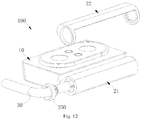
- an image capturing assembly 200 includes a housing 110 and an image capturing module 100.
- the housing 110 includes a side wall 112, and the side wall 112 has a notch 113.
- the housing 110 is provided with an accommodating groove 117 communicated with the notch 113.
- the image capturing module 100 includes an image capturing portion 10 and a rotating shaft portion 20, and the image capturing portion 10 includes an image capturing surface 11 and a non-image capturing surface 12 opposite to each other.
- the rotating shaft portion 20 is accommodated in the notch 113, and the image capturing portion 10 is rotated with respect to the housing 110 through the rotating shaft portion 20.
- the rotating shaft portion 20 includes a rotating shaft 21 and a movable member 22, and the movable member 22 is fitted over the rotating shaft 21.
- the image capturing portion 10 is connected with the rotating shaft 21 and configured to rotate back and forth among a first position, a second position and a third position driven by the rotating shaft 21.
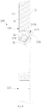
- the image capturing portion 10 When being in the first position, the image capturing portion 10 is at least partially received in the accommodating groove 117, and a position of the movable member 22 is limited such that the movable member 22 has smooth transition and butt joint with the image capturing surface 11 of the image capturing portion 10, as illustrated in Fig. 6 .
- the movable member 22 When the image capturing portion 10 is rotated from the first position to the second position, the movable member 22 is driven by the rotating shaft 21 to rotate to a position where the movable member 22 abuts against an inner side surface of the notch 113, as illustrated in Fig. 7 .
- the image capturing portion 10 When being in the third position, the image capturing portion 10 is fully unfolded with respect to the accommodating groove 117, and the position of the movable member 22 is limited such that the movable member 22 has smooth transition and butt joint with the non-image capturing surface 12 of the image capturing portion 10, as illustrated in Fig. 8 .
- the image capturing assembly 200 may be applied to an electronic device 500.
- the electronic device 500 is a mobile terminal such as a mobile phone, an intelligent wearable device or a tablet computer. It may be understood that the electronic device 500 includes, but is not limited to examples of the embodiment.
- the movable member 22 enables the image capturing portion 10 to move from the second position to the third position, thus increasing a rotation range of the image capturing portion 10, and ensuring a smooth rotation of the image capturing module 100 for the front image capturing.
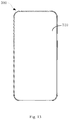
- the housing 110 is a front housing of the electronic device 500 and has a roughly rectangular shape.
- the housing 110 is a carrier member of the electronic device 500 and is configured to carry most parts of the electronic device 500.
- the housing 110 may be made of plastics or metal materials, or may be configured as an integrated structure by adopting an in-mold injection process with plastics and metal.
- the housing 110 includes a base plate, and the side wall 112 extends from an edge of the base plate.
- the base plate is roughly rectangular.
- the side wall 112 has an annular shape, and the notch 113 is formed at a top portion of the side wall 112, such that the image capturing module 100 is disposed at a top of the electronic device 500. As illustrated by an orientation in Fig. 13 , the top of the electronic device 500 is an upper position.
- the side wall 112 includes a side wall segment 114 corresponding to the notch 113, and the side wall segment 114 protrudes from a bottom surface 118 of the accommodating groove 117 and partially covers the rotating shaft portion 20. In this way, the side wall segment 114 covers at least part of the rotating shaft portion 20, thus reducing a gap between the side wall segment 114 and the rotating shaft portion 20. In addition, the side wall segment 114 can also improve the strength and the reliability of the housing 110.
- the image capturing portion 10 has a square shape, and it may be understood that the image capturing portion 10 is provided with cameras and other components therein.
- the image capturing portion 10 is provided with two cameras therein.
- one of the cameras is a telephoto camera and the other one thereof is a wide-angle camera.
- a flashlight may also be provided in the image capturing portion 10 and disposed between the two cameras.
- the flashlight may supplement light for the electronic device 500.
- the flashlight may be used to illuminate surrounding scenes.
- the flashlight may supplement light for the image capturing process to improve the image capturing quality of the electronic device 500. It may be understood that both the camera and the flashlight are exposed out of the image capturing portion 10.
- the image capturing portion 10 may be provided with other functional elements therein, such as a receiver, a microphone, and the like.
- the rotating shaft 21 drives the image capturing portion 10 to rotate to a position where the image capturing portion 10 abuts against an outer surface 1151 of the side wall segment 114, and the side wall segment 114 is configured to prevent the movable member 22 from rotating from the second position to the third position.
- the rotating shaft portion 20 has a roughly cylindrical shape, and provides a rotating center for the rotation of the image capturing portion 10.
- the side wall segment 114 covering at least part of the rotating shaft portion 20 refers to that there is an overlap between a lateral dimension of the side wall segment 114 and a radial dimension of the rotating shaft portion 20.
- a lateral dimension L of a part of the side wall segment 114 covering the rotating shaft portion 20 is greater than or equal to half of a radius R of the rotating shaft portion 20. That is, L/R ⁇ 1/2.
- the lateral dimension L is 1.5mm and the radius R is 3mm.
- the lateral dimension L is half of the radius R. It may be understood that the larger the ratio of L/R, the smaller the gap formed between the rotating shaft portion 20 and the side wall segment 114.
- the image capturing module 100 is a rear image capturing module of the electronic device 500, and thus the electronic device 500 can capture an image of a scene behind the electronic device 500.
- the image capturing module 100 is a front image capturing module of the electronic device 500, and thus the electronic device 500 can capture an image of a scene in front of the electronic device 500.
- the image capturing portion 10 is arranged in the first position.
- the image capturing portion 10 may be rotated from the first position to the third position according to specific requirements.
- the electronic device 500 may control the image capturing portion 10 to rotate to the third position. Therefore, the electronic device 500 does not need a front camera fixed at a front side thereof, thus saving an internal space of the electronic device 500, avoiding an interference between the front camera and a display screen 510, and thereby increasing a screen-to-body ratio of the electronic device 500.
- the screen-to-body ratio of the electronic device 500 refers to a ratio of a display area to a non-display area of the electronic device 500 at the front side of the electronic device 500.
- an angle rotated by the image capturing portion 10 is greater than or equal to 180 degrees.
- an image capturing range of the image capturing portion 10 is relatively large, thus satisfying the requirements of image capturing at different angles.
- the image capturing portion 10 may be held at any position between the first position and the third position.
- the image capturing portion 10 may be held in the second position.
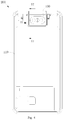
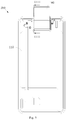
- the first position is the position illustrated in Fig. 4 or 6
- the second position is the position illustrated in Fig. 7
- the third position is the position illustrated in Fig. 5 or 8 .
- the side wall segment 114 covers at least part of the rotating shaft portion 20 to reduce the gap between the rotating shaft portion 20 and the side wall segment 114.
- the rotating shaft portion 20 and the image capturing portion 10 are an integral member, the rotating shaft portion 20 will abut against the inner side surface of the side wall segment 114 such that the image capturing portion 10 cannot continue rotating. Therefore, the side wall segment 114 limits a movement space of the image capturing module 100.
- the movable member 22 is fitted over the rotating shaft 21. It may be understood that the movable members 22 are arranged outside the rotating shaft 21.
- the movable member 22 When the image capturing portion 10 is rotated from the first position to the second position, the movable member 22 abuts against the inner side surface of the side wall segment 114, while the rotating shaft 21 arranged inside the movable member 22 may be rotated from the second position to the third position together with the image capturing portion 10 due to its small size.
- the housing 110 includes a surrounding wall 116 connected with the side wall 112, and the surrounding wall 116 and the side wall 112 enclose the accommodating groove 117 communicated with the notch 113.
- the image capturing portion 10 is in the first position, the image capturing portion 10 is at least partially accommodated in the accommodating groove 117.
- the surrounding wall 116 may define an independent space for accommodating the image capturing module 100, avoiding an interference between the image capturing portion 10 and other elements of the electronic device 500.
- the surrounding wall 116 can prevent internal parts of the electronic device 500 from being exposed, thus improving an appearance performance of the electronic device 500. It may be understood that a dimension of the accommodating groove 117 is larger than that of the image capturing portion 10, and thus the image capturing portion 10 can be accommodated.
- the image capturing portion 10 is partially accommodated in the accommodating groove 117. It may be understood that, in other embodiments, the image capturing portion 10 can be totally accommodated in the accommodating groove 117.
- an inner surface of the side wall segment 114 includes a first arc surface 1141, and a bottom surface 118 of the accommodating groove is includes a second arc surface 1181.
- the first arc surface 1141 and the second arc surface 1181 are smoothly connected to form an arc surface 1182 of the housing.
- the arc surface 1182 of the housing is spaced apart from an outer surface of the rotating shaft portion 20, and a radian of the arc surface 1182 of housing is consistent with that of the rotating shaft portion 20.
- the arc surface 1182 of the housing matches with a contour of the rotating shaft portion 20, such that a fitted structure of the rotating shaft portion 20 and the housing 110 is compact.
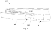
- the outer surface 1151 of the side wall 112 is provided with a slot 1152, and when the image capturing portion 10 is in the third position, an edge of the image capturing portion 10 abuts against and received in the slot 1152.
- the slot 1152 allows a close fit of the image capturing portion 10 and the outer surface of the side wall segment 114, such that when the image capturing portion 10 is in the third position, the appearance of the electronic device 500 is aesthetic.
- the slot 1152 has a strip shape, and a length of the slot 1152 is greater than that of the edge of the image capturing portion 10.
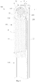
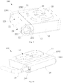
- the image capturing assembly 200 includes a stop member 210 fitted over the rotating shaft 21 and fixed to the housing 110.
- the movable member 22 includes a rotating ring 221 arranged at an end of the rotating shaft 21.
- the rotating ring 221 is provided with a first stop portion 222 and a second stop portion 223.
- the stop member 210 abuts against the first stop portion 222.
- the stop member 210 abuts against the second stop portion 223.
- the stop member 210 is fitted with the first stop portion 222 and the second stop portion 223, the movable member 22 can be prevented from being rotated along with the image capturing portion 10 from the second position to the third position, so as not to press the side wall segment 114, thereby protecting the side wall segment 114 and improving the rotation safety of the image capturing portion 10.
- the movable member 22 is rotated synchronously with the image capturing portion 10 along with the rotation of the rotating shaft 21 through a static friction force between the movable member 22 and the rotating shaft 21.
- the stop member 210 abuts against the second stop portion 223 to provide an opposite force for the rotation direction of the movable member 22, and the opposite force is greater than the static friction force between the movable member 22 and the rotating shaft 21, so as to prevent the movable member 22 from continuing rotating to the third position.
- the image capturing portion 10 can continue rotating from the second position to the third position.
- the rotating ring 221 is provided with a through hole 224, and the rotating shaft 21 passes through the through hole 224 and is arranged therein.
- An inner side surface of the through hole 224 is provided with an arc groove 225.
- the first stop portion 222 and the second stop portion 223 are provided at two ends of the arc groove 225, respectively.
- the stop member 210 includes a stop ring 211 and a protrusion 212 arranged on an outer side surface of the stop ring 211, the stop ring 211 is fitted over the rotating shaft 21, and the protrusion 212 extends into the arc groove 225 to abut against the first stop portion 222 or the second stop portion 223.
- the structures of the stop member 210 and the movable member 22 are simple and easy to form, thus reducing the cost of the image capturing module 100.
- the protrusion 212 abuts against the first stop portion 222, and as illustrated in Fig. 7 and Fig. 8 , the protrusion 212 abuts against the second stop portion 223.
- the movable member 22 includes a connecting sheet 226 connected to the rotating ring 221, and the connecting sheet 226 extends along an axial direction of the rotating shaft portion 20.
- An outer surface of the connecting sheet 226 includes an arc surface 2261 and a flat surface 2262.
- the movable member 22 is compactly fitted with the image capturing portion 10, thus miniaturizing the image capturing module 100, and also making the electronic device 500 aesthetic.
- an orientation of the image capturing surface 11 is the same with an image capturing direction of the image capturing portion 10, and the image capturing surface 11 in the present disclosure is a flat surface.
- the image capturing assembly 200 includes a driving mechanism 230, and the driving mechanism 230 includes a driving member 231 and a transmission member 232.
- the transmission member 232 is connected to the rotating shaft 21, and the driving member 231 is configured to drive the rotating shaft 21 to rotate through the transmission member 232.
- the driving mechanism 230 drives the rotating shaft 21 to rotate so as to drive the image capturing module 100 to rotate.
- the driving member 231 is a motor
- the transmission member 232 is a transmission gear 232.
- a processor of the electronic device 500 may control the driving mechanism 230 to operate, so as to control the image capturing portion 10 to rotate to different positions.
- the image capturing module 100 includes a wire 30.
- the wire 30 is connected to the components in the image capturing portion 10 and extends out of the image capturing module 100 through the rotating shaft 20.
- the wire 30 may transmit signals and provide electric energy to the image capturing module 100.
- the wire 30 is a coaxial line, such that the wire 30 tends not to be twisted and damaged when the image capturing portion 10 is rotated, and thus the service life of the wire 30 is prolonged.
- the image capturing assembly 200 includes a wire clip 240, and the wire clip 240 is fixed to the housing 110 and clamps the wire 30.
- the wire clip 240 may be fixed to the housing 110 with a fastener such as a screw. In this way, the wire clip 240 can avoid that the wire 30 arranged in the image capturing module 100 is subjected to an external pulling force and thus cannot be normally connected with the components inside the image capturing module 200.
- the image capturing assembly 200 further includes a wire gathering ring 250 arranged to the wire 30 and embedded in the image capturing module 100.
- the wire gathering ring 250 is configured to gather the wire 30. It may be understood that when a plurality of wires 30 are provided, the plurality of wires 30 tend to be loose and occupy a relatively large space volume. The wire gathering ring 250 gathers the wires 30, so as to reduce the space occupied by wires 30. It may be understood that when a clamping force of the wire gathering ring 250 is large enough, the wire gathering ring 250 can also clamp the wires 30 to prevent the wires 30 from being loosened.
Landscapes
- Engineering & Computer Science (AREA)
- Signal Processing (AREA)
- Multimedia (AREA)
- Computer Hardware Design (AREA)
- Theoretical Computer Science (AREA)
- Human Computer Interaction (AREA)
- Physics & Mathematics (AREA)
- General Engineering & Computer Science (AREA)
- General Physics & Mathematics (AREA)
- Studio Devices (AREA)
- Telephone Set Structure (AREA)
Applications Claiming Priority (2)
| Application Number | Priority Date | Filing Date | Title |
|---|---|---|---|
| CN201810184560.5A CN110233950B (zh) | 2018-03-06 | 2018-03-06 | 摄像组件及电子装置 |
| PCT/CN2019/075904 WO2019170010A1 (zh) | 2018-03-06 | 2019-02-22 | 摄像组件及电子装置 |
Publications (3)
| Publication Number | Publication Date |
|---|---|
| EP3722921A1 true EP3722921A1 (de) | 2020-10-14 |
| EP3722921A4 EP3722921A4 (de) | 2020-12-30 |
| EP3722921B1 EP3722921B1 (de) | 2021-09-01 |
Family
ID=67846409
Family Applications (1)
| Application Number | Title | Priority Date | Filing Date |
|---|---|---|---|
| EP19763246.6A Active EP3722921B1 (de) | 2018-03-06 | 2019-02-22 | Bildgebungsanordnung und elektronische vorrichtung |
Country Status (4)
| Country | Link |
|---|---|
| US (1) | US11258934B2 (de) |
| EP (1) | EP3722921B1 (de) |
| CN (1) | CN110233950B (de) |
| WO (1) | WO2019170010A1 (de) |
Families Citing this family (10)
| Publication number | Priority date | Publication date | Assignee | Title |
|---|---|---|---|---|
| CN110233910B (zh) * | 2018-03-06 | 2021-07-13 | Oppo广东移动通信有限公司 | 壳体、摄像组件及电子装置 |
| CN108337381B (zh) * | 2018-03-14 | 2019-11-19 | 维沃移动通信有限公司 | 一种镜头控制方法及移动终端 |
| USD920273S1 (en) * | 2019-01-09 | 2021-05-25 | Huawei Technologies Co., Ltd. | Mobile phone |
| JP1651187S (de) * | 2019-01-09 | 2020-01-27 | ||
| TWM579415U (zh) * | 2019-03-08 | 2019-06-11 | 華碩電腦股份有限公司 | 功能組件以及包含其之電子裝置 |
| US11546451B2 (en) * | 2019-05-15 | 2023-01-03 | Asustek Computer Inc. | Electronic device |
| JP1653373S (ja) * | 2019-07-11 | 2020-02-25 | 携帯電話機 | |
| CN210112121U (zh) * | 2019-08-20 | 2020-02-21 | 三赢科技(深圳)有限公司 | 摄像模组及具有该摄像模组的电子装置 |
| CN112543263B (zh) * | 2019-09-20 | 2023-06-16 | 富泰华工业(深圳)有限公司 | 摄像头及电子装置 |
| CN115277891A (zh) * | 2021-04-29 | 2022-11-01 | 北京小米移动软件有限公司 | 一种设有翻转式摄像模组的移动终端 |
Family Cites Families (16)
| Publication number | Priority date | Publication date | Assignee | Title |
|---|---|---|---|---|
| US6898301B2 (en) * | 2000-07-10 | 2005-05-24 | Casio Computer Co., Ltd. | Authentication system based on fingerprint and electronic device employed for the system |
| JP2004056383A (ja) * | 2002-07-18 | 2004-02-19 | Fujitsu Ltd | 携帯型電子機器および撮像装置 |
| KR100463432B1 (ko) * | 2002-12-10 | 2004-12-23 | 삼성전기주식회사 | 회전가능한 카메라를 갖는 휴대전화기의 힌지장치 |
| TWM249388U (en) * | 2004-01-30 | 2004-11-01 | High Tech Comp Corp | Handheld electronic device |
| US7264171B2 (en) * | 2004-05-31 | 2007-09-04 | Wistron Corp. | Electronic device with embedded image capture module |
| KR20080004546A (ko) * | 2005-03-30 | 2008-01-09 | 코닌클리케 필립스 일렉트로닉스 엔.브이. | 회전식 카메라 장치를 갖춘 휴대용 전자 디바이스 |
| CN100368851C (zh) * | 2005-05-27 | 2008-02-13 | 黄金泉 | 照相手机镜头转向装置 |
| CN201957073U (zh) * | 2010-11-26 | 2011-08-31 | 英业达股份有限公司 | 具有摄像功能的电子装置 |
| CN105453526B (zh) * | 2014-07-23 | 2018-11-06 | 华为技术有限公司 | 一种终端设备 |
| CN204334742U (zh) * | 2014-12-01 | 2015-05-13 | 广东亿纬电子有限公司 | 一种智能手机旋转摄像头结构及智能手机 |
| CN104469114A (zh) * | 2014-12-08 | 2015-03-25 | 路宽 | 移动终端及全自动翻转式摄像组件 |
| CN106464755B (zh) * | 2015-02-28 | 2019-09-03 | 华为技术有限公司 | 自动调整摄像头的方法和电子设备 |
| CN105979032B (zh) * | 2016-04-28 | 2018-03-27 | 广东欧珀移动通信有限公司 | 折叠机构及移动终端 |
| CN205961284U (zh) * | 2016-08-23 | 2017-02-15 | 郴州希典科技有限公司 | 旋转角度可控的摄像头 |
| CN206117742U (zh) * | 2016-09-06 | 2017-04-19 | 深圳市渴望通信有限公司 | 手机 |
| US20180091711A1 (en) * | 2016-09-23 | 2018-03-29 | Wen-Tse HUANG | Pair of Eyeglasses with Camera Lenses |
-
2018
- 2018-03-06 CN CN201810184560.5A patent/CN110233950B/zh active Active
-
2019
- 2019-02-22 EP EP19763246.6A patent/EP3722921B1/de active Active
- 2019-02-22 WO PCT/CN2019/075904 patent/WO2019170010A1/zh not_active Ceased
-
2020
- 2020-06-23 US US16/909,426 patent/US11258934B2/en not_active Expired - Fee Related
Also Published As
| Publication number | Publication date |
|---|---|
| WO2019170010A1 (zh) | 2019-09-12 |
| CN110233950B (zh) | 2020-06-05 |
| CN110233950A (zh) | 2019-09-13 |
| US11258934B2 (en) | 2022-02-22 |
| EP3722921A4 (de) | 2020-12-30 |
| US20200322515A1 (en) | 2020-10-08 |
| EP3722921B1 (de) | 2021-09-01 |
Similar Documents
| Publication | Publication Date | Title |
|---|---|---|
| US11258934B2 (en) | Image capturing assembly and electronic device | |
| WO2020108274A1 (en) | Transmission mechanism and mobile terminal | |
| CN207491003U (zh) | 移动终端 | |
| US20190253533A1 (en) | Mobile terminal | |
| EP3565226B1 (de) | Mobiles endgerät | |
| US20190253540A1 (en) | Mobile terminal | |
| CN106790826A (zh) | 电子设备 | |
| CN113489814B (zh) | 电子设备 | |
| CN207491004U (zh) | 移动终端 | |
| US11558497B2 (en) | Mobile terminal | |
| CN108055426A (zh) | 摄像头组装结构及移动终端 | |
| CN208128321U (zh) | 移动终端 | |
| US7392071B2 (en) | Rotary module with digital camera module | |
| CN208128322U (zh) | 移动终端 | |
| CN110233951A (zh) | 摄像模组、摄像组件及电子装置 | |
| CN210112121U (zh) | 摄像模组及具有该摄像模组的电子装置 | |
| CN110233910B (zh) | 壳体、摄像组件及电子装置 | |
| CN208079214U (zh) | 摄像头组装结构及移动终端 | |
| KR20040077291A (ko) | 휴대폰용 카메라 모듈 | |
| CN112904647A (zh) | 一种运动相机 | |
| KR20040061723A (ko) | 이동통신 단말기의 카메라 장치 | |
| CN112311915B (zh) | 移动终端 | |
| KR100447628B1 (ko) | 카메라 장착 휴대폰 | |
| KR100593893B1 (ko) | 회전형 카메라를 구비한 휴대폰 | |
| HK40023189B (en) | Electronic device |
Legal Events
| Date | Code | Title | Description |
|---|---|---|---|
| STAA | Information on the status of an ep patent application or granted ep patent |
Free format text: STATUS: THE INTERNATIONAL PUBLICATION HAS BEEN MADE |
|
| PUAI | Public reference made under article 153(3) epc to a published international application that has entered the european phase |
Free format text: ORIGINAL CODE: 0009012 |
|
| STAA | Information on the status of an ep patent application or granted ep patent |
Free format text: STATUS: REQUEST FOR EXAMINATION WAS MADE |
|
| 17P | Request for examination filed |
Effective date: 20200706 |
|
| AK | Designated contracting states |
Kind code of ref document: A1 Designated state(s): AL AT BE BG CH CY CZ DE DK EE ES FI FR GB GR HR HU IE IS IT LI LT LU LV MC MK MT NL NO PL PT RO RS SE SI SK SM TR |
|
| AX | Request for extension of the european patent |
Extension state: BA ME |
|
| REG | Reference to a national code |
Ref country code: DE Ref legal event code: R079 Ref document number: 602019007393 Country of ref document: DE Free format text: PREVIOUS MAIN CLASS: G06F0001160000 Ipc: H04M0001020000 |
|
| A4 | Supplementary search report drawn up and despatched |
Effective date: 20201202 |
|
| RIC1 | Information provided on ipc code assigned before grant |
Ipc: H04N 5/225 20060101ALI20201126BHEP Ipc: G06F 1/16 20060101ALI20201126BHEP Ipc: H04M 1/02 20060101AFI20201126BHEP |
|
| GRAP | Despatch of communication of intention to grant a patent |
Free format text: ORIGINAL CODE: EPIDOSNIGR1 |
|
| STAA | Information on the status of an ep patent application or granted ep patent |
Free format text: STATUS: GRANT OF PATENT IS INTENDED |
|
| DAV | Request for validation of the european patent (deleted) | ||
| DAX | Request for extension of the european patent (deleted) | ||
| INTG | Intention to grant announced |
Effective date: 20210602 |
|
| GRAS | Grant fee paid |
Free format text: ORIGINAL CODE: EPIDOSNIGR3 |
|
| GRAA | (expected) grant |
Free format text: ORIGINAL CODE: 0009210 |
|
| STAA | Information on the status of an ep patent application or granted ep patent |
Free format text: STATUS: THE PATENT HAS BEEN GRANTED |
|
| AK | Designated contracting states |
Kind code of ref document: B1 Designated state(s): AL AT BE BG CH CY CZ DE DK EE ES FI FR GB GR HR HU IE IS IT LI LT LU LV MC MK MT NL NO PL PT RO RS SE SI SK SM TR |
|
| REG | Reference to a national code |
Ref country code: GB Ref legal event code: FG4D |
|
| REG | Reference to a national code |
Ref country code: CH Ref legal event code: EP Ref country code: AT Ref legal event code: REF Ref document number: 1427464 Country of ref document: AT Kind code of ref document: T Effective date: 20210915 |
|
| REG | Reference to a national code |
Ref country code: DE Ref legal event code: R096 Ref document number: 602019007393 Country of ref document: DE |
|
| REG | Reference to a national code |
Ref country code: IE Ref legal event code: FG4D |
|
| REG | Reference to a national code |
Ref country code: LT Ref legal event code: MG9D |
|
| REG | Reference to a national code |
Ref country code: NL Ref legal event code: MP Effective date: 20210901 |
|
| PG25 | Lapsed in a contracting state [announced via postgrant information from national office to epo] |
Ref country code: HR Free format text: LAPSE BECAUSE OF FAILURE TO SUBMIT A TRANSLATION OF THE DESCRIPTION OR TO PAY THE FEE WITHIN THE PRESCRIBED TIME-LIMIT Effective date: 20210901 Ref country code: FI Free format text: LAPSE BECAUSE OF FAILURE TO SUBMIT A TRANSLATION OF THE DESCRIPTION OR TO PAY THE FEE WITHIN THE PRESCRIBED TIME-LIMIT Effective date: 20210901 Ref country code: NO Free format text: LAPSE BECAUSE OF FAILURE TO SUBMIT A TRANSLATION OF THE DESCRIPTION OR TO PAY THE FEE WITHIN THE PRESCRIBED TIME-LIMIT Effective date: 20211201 Ref country code: LT Free format text: LAPSE BECAUSE OF FAILURE TO SUBMIT A TRANSLATION OF THE DESCRIPTION OR TO PAY THE FEE WITHIN THE PRESCRIBED TIME-LIMIT Effective date: 20210901 Ref country code: BG Free format text: LAPSE BECAUSE OF FAILURE TO SUBMIT A TRANSLATION OF THE DESCRIPTION OR TO PAY THE FEE WITHIN THE PRESCRIBED TIME-LIMIT Effective date: 20211201 Ref country code: SE Free format text: LAPSE BECAUSE OF FAILURE TO SUBMIT A TRANSLATION OF THE DESCRIPTION OR TO PAY THE FEE WITHIN THE PRESCRIBED TIME-LIMIT Effective date: 20210901 Ref country code: RS Free format text: LAPSE BECAUSE OF FAILURE TO SUBMIT A TRANSLATION OF THE DESCRIPTION OR TO PAY THE FEE WITHIN THE PRESCRIBED TIME-LIMIT Effective date: 20210901 Ref country code: ES Free format text: LAPSE BECAUSE OF FAILURE TO SUBMIT A TRANSLATION OF THE DESCRIPTION OR TO PAY THE FEE WITHIN THE PRESCRIBED TIME-LIMIT Effective date: 20210901 |
|
| REG | Reference to a national code |
Ref country code: AT Ref legal event code: MK05 Ref document number: 1427464 Country of ref document: AT Kind code of ref document: T Effective date: 20210901 |
|
| PG25 | Lapsed in a contracting state [announced via postgrant information from national office to epo] |
Ref country code: PL Free format text: LAPSE BECAUSE OF FAILURE TO SUBMIT A TRANSLATION OF THE DESCRIPTION OR TO PAY THE FEE WITHIN THE PRESCRIBED TIME-LIMIT Effective date: 20210901 Ref country code: LV Free format text: LAPSE BECAUSE OF FAILURE TO SUBMIT A TRANSLATION OF THE DESCRIPTION OR TO PAY THE FEE WITHIN THE PRESCRIBED TIME-LIMIT Effective date: 20210901 Ref country code: GR Free format text: LAPSE BECAUSE OF FAILURE TO SUBMIT A TRANSLATION OF THE DESCRIPTION OR TO PAY THE FEE WITHIN THE PRESCRIBED TIME-LIMIT Effective date: 20211202 |
|
| PG25 | Lapsed in a contracting state [announced via postgrant information from national office to epo] |
Ref country code: AT Free format text: LAPSE BECAUSE OF FAILURE TO SUBMIT A TRANSLATION OF THE DESCRIPTION OR TO PAY THE FEE WITHIN THE PRESCRIBED TIME-LIMIT Effective date: 20210901 |
|
| PG25 | Lapsed in a contracting state [announced via postgrant information from national office to epo] |
Ref country code: IS Free format text: LAPSE BECAUSE OF FAILURE TO SUBMIT A TRANSLATION OF THE DESCRIPTION OR TO PAY THE FEE WITHIN THE PRESCRIBED TIME-LIMIT Effective date: 20220101 Ref country code: SM Free format text: LAPSE BECAUSE OF FAILURE TO SUBMIT A TRANSLATION OF THE DESCRIPTION OR TO PAY THE FEE WITHIN THE PRESCRIBED TIME-LIMIT Effective date: 20210901 Ref country code: SK Free format text: LAPSE BECAUSE OF FAILURE TO SUBMIT A TRANSLATION OF THE DESCRIPTION OR TO PAY THE FEE WITHIN THE PRESCRIBED TIME-LIMIT Effective date: 20210901 Ref country code: RO Free format text: LAPSE BECAUSE OF FAILURE TO SUBMIT A TRANSLATION OF THE DESCRIPTION OR TO PAY THE FEE WITHIN THE PRESCRIBED TIME-LIMIT Effective date: 20210901 Ref country code: PT Free format text: LAPSE BECAUSE OF FAILURE TO SUBMIT A TRANSLATION OF THE DESCRIPTION OR TO PAY THE FEE WITHIN THE PRESCRIBED TIME-LIMIT Effective date: 20220103 Ref country code: NL Free format text: LAPSE BECAUSE OF FAILURE TO SUBMIT A TRANSLATION OF THE DESCRIPTION OR TO PAY THE FEE WITHIN THE PRESCRIBED TIME-LIMIT Effective date: 20210901 Ref country code: EE Free format text: LAPSE BECAUSE OF FAILURE TO SUBMIT A TRANSLATION OF THE DESCRIPTION OR TO PAY THE FEE WITHIN THE PRESCRIBED TIME-LIMIT Effective date: 20210901 Ref country code: CZ Free format text: LAPSE BECAUSE OF FAILURE TO SUBMIT A TRANSLATION OF THE DESCRIPTION OR TO PAY THE FEE WITHIN THE PRESCRIBED TIME-LIMIT Effective date: 20210901 Ref country code: AL Free format text: LAPSE BECAUSE OF FAILURE TO SUBMIT A TRANSLATION OF THE DESCRIPTION OR TO PAY THE FEE WITHIN THE PRESCRIBED TIME-LIMIT Effective date: 20210901 |
|
| REG | Reference to a national code |
Ref country code: DE Ref legal event code: R097 Ref document number: 602019007393 Country of ref document: DE |
|
| PLBE | No opposition filed within time limit |
Free format text: ORIGINAL CODE: 0009261 |
|
| STAA | Information on the status of an ep patent application or granted ep patent |
Free format text: STATUS: NO OPPOSITION FILED WITHIN TIME LIMIT |
|
| PG25 | Lapsed in a contracting state [announced via postgrant information from national office to epo] |
Ref country code: IT Free format text: LAPSE BECAUSE OF FAILURE TO SUBMIT A TRANSLATION OF THE DESCRIPTION OR TO PAY THE FEE WITHIN THE PRESCRIBED TIME-LIMIT Effective date: 20210901 Ref country code: DK Free format text: LAPSE BECAUSE OF FAILURE TO SUBMIT A TRANSLATION OF THE DESCRIPTION OR TO PAY THE FEE WITHIN THE PRESCRIBED TIME-LIMIT Effective date: 20210901 |
|
| 26N | No opposition filed |
Effective date: 20220602 |
|
| PG25 | Lapsed in a contracting state [announced via postgrant information from national office to epo] |
Ref country code: SI Free format text: LAPSE BECAUSE OF FAILURE TO SUBMIT A TRANSLATION OF THE DESCRIPTION OR TO PAY THE FEE WITHIN THE PRESCRIBED TIME-LIMIT Effective date: 20210901 |
|
| PG25 | Lapsed in a contracting state [announced via postgrant information from national office to epo] |
Ref country code: MC Free format text: LAPSE BECAUSE OF FAILURE TO SUBMIT A TRANSLATION OF THE DESCRIPTION OR TO PAY THE FEE WITHIN THE PRESCRIBED TIME-LIMIT Effective date: 20210901 |
|
| REG | Reference to a national code |
Ref country code: CH Ref legal event code: PL |
|
| REG | Reference to a national code |
Ref country code: BE Ref legal event code: MM Effective date: 20220228 |
|
| PG25 | Lapsed in a contracting state [announced via postgrant information from national office to epo] |
Ref country code: LU Free format text: LAPSE BECAUSE OF NON-PAYMENT OF DUE FEES Effective date: 20220222 |
|
| PG25 | Lapsed in a contracting state [announced via postgrant information from national office to epo] |
Ref country code: LI Free format text: LAPSE BECAUSE OF NON-PAYMENT OF DUE FEES Effective date: 20220228 Ref country code: IE Free format text: LAPSE BECAUSE OF NON-PAYMENT OF DUE FEES Effective date: 20220222 Ref country code: CH Free format text: LAPSE BECAUSE OF NON-PAYMENT OF DUE FEES Effective date: 20220228 |
|
| PG25 | Lapsed in a contracting state [announced via postgrant information from national office to epo] |
Ref country code: BE Free format text: LAPSE BECAUSE OF NON-PAYMENT OF DUE FEES Effective date: 20220228 |
|
| P01 | Opt-out of the competence of the unified patent court (upc) registered |
Effective date: 20230412 |
|
| PG25 | Lapsed in a contracting state [announced via postgrant information from national office to epo] |
Ref country code: MK Free format text: LAPSE BECAUSE OF FAILURE TO SUBMIT A TRANSLATION OF THE DESCRIPTION OR TO PAY THE FEE WITHIN THE PRESCRIBED TIME-LIMIT Effective date: 20210901 Ref country code: CY Free format text: LAPSE BECAUSE OF FAILURE TO SUBMIT A TRANSLATION OF THE DESCRIPTION OR TO PAY THE FEE WITHIN THE PRESCRIBED TIME-LIMIT Effective date: 20210901 |
|
| PG25 | Lapsed in a contracting state [announced via postgrant information from national office to epo] |
Ref country code: HU Free format text: LAPSE BECAUSE OF FAILURE TO SUBMIT A TRANSLATION OF THE DESCRIPTION OR TO PAY THE FEE WITHIN THE PRESCRIBED TIME-LIMIT; INVALID AB INITIO Effective date: 20190222 |
|
| PGFP | Annual fee paid to national office [announced via postgrant information from national office to epo] |
Ref country code: FR Payment date: 20240220 Year of fee payment: 6 |
|
| PG25 | Lapsed in a contracting state [announced via postgrant information from national office to epo] |
Ref country code: TR Free format text: LAPSE BECAUSE OF FAILURE TO SUBMIT A TRANSLATION OF THE DESCRIPTION OR TO PAY THE FEE WITHIN THE PRESCRIBED TIME-LIMIT Effective date: 20210901 |
|
| PG25 | Lapsed in a contracting state [announced via postgrant information from national office to epo] |
Ref country code: MT Free format text: LAPSE BECAUSE OF FAILURE TO SUBMIT A TRANSLATION OF THE DESCRIPTION OR TO PAY THE FEE WITHIN THE PRESCRIBED TIME-LIMIT Effective date: 20210901 |
|
| PG25 | Lapsed in a contracting state [announced via postgrant information from national office to epo] |
Ref country code: FR Free format text: LAPSE BECAUSE OF NON-PAYMENT OF DUE FEES Effective date: 20250228 |
|
| PGFP | Annual fee paid to national office [announced via postgrant information from national office to epo] |
Ref country code: GB Payment date: 20260106 Year of fee payment: 8 |
|
| PGFP | Annual fee paid to national office [announced via postgrant information from national office to epo] |
Ref country code: DE Payment date: 20251230 Year of fee payment: 8 |