EP3723055B1 - Blattverarbeitungsgerät und verfahren zur bestimmung des eintritts von fremdkörpern - Google Patents
Blattverarbeitungsgerät und verfahren zur bestimmung des eintritts von fremdkörpern Download PDFInfo
- Publication number
- EP3723055B1 EP3723055B1 EP20167951.1A EP20167951A EP3723055B1 EP 3723055 B1 EP3723055 B1 EP 3723055B1 EP 20167951 A EP20167951 A EP 20167951A EP 3723055 B1 EP3723055 B1 EP 3723055B1
- Authority
- EP
- European Patent Office
- Prior art keywords
- coils
- section
- foreign object
- processing apparatus
- sheet processing
- Prior art date
- Legal status (The legal status is an assumption and is not a legal conclusion. Google has not performed a legal analysis and makes no representation as to the accuracy of the status listed.)
- Active
Links
Images






Classifications
-
- G—PHYSICS
- G07—CHECKING-DEVICES
- G07D—HANDLING OF COINS OR VALUABLE PAPERS, e.g. TESTING, SORTING BY DENOMINATIONS, COUNTING, DISPENSING, CHANGING OR DEPOSITING
- G07D7/00—Testing specially adapted to determine the identity or genuineness of valuable papers or for segregating those which are unacceptable, e.g. banknotes that are alien to a currency
- G07D7/181—Testing mechanical properties or condition, e.g. wear or tear
- G07D7/189—Detecting attached objects, e.g. tapes or clips
-
- B—PERFORMING OPERATIONS; TRANSPORTING
- B65—CONVEYING; PACKING; STORING; HANDLING THIN OR FILAMENTARY MATERIAL
- B65H—HANDLING THIN OR FILAMENTARY MATERIAL, e.g. SHEETS, WEBS, CABLES
- B65H7/00—Controlling article feeding, separating, pile-advancing, or associated apparatus, to take account of incorrect feeding, absence of articles, or presence of faulty articles
- B65H7/02—Controlling article feeding, separating, pile-advancing, or associated apparatus, to take account of incorrect feeding, absence of articles, or presence of faulty articles by feelers or detectors
-
- B—PERFORMING OPERATIONS; TRANSPORTING
- B65—CONVEYING; PACKING; STORING; HANDLING THIN OR FILAMENTARY MATERIAL
- B65H—HANDLING THIN OR FILAMENTARY MATERIAL, e.g. SHEETS, WEBS, CABLES
- B65H5/00—Feeding articles separated from piles; Feeding articles to machines
- B65H5/06—Feeding articles separated from piles; Feeding articles to machines by rollers or balls, e.g. between rollers
- B65H5/062—Feeding articles separated from piles; Feeding articles to machines by rollers or balls, e.g. between rollers between rollers or balls
-
- G—PHYSICS
- G01—MEASURING; TESTING
- G01V—GEOPHYSICS; GRAVITATIONAL MEASUREMENTS; DETECTING MASSES OR OBJECTS; TAGS
- G01V3/00—Electric or magnetic prospecting or detecting; Measuring magnetic field characteristics of the earth, e.g. declination, deviation
- G01V3/08—Electric or magnetic prospecting or detecting; Measuring magnetic field characteristics of the earth, e.g. declination, deviation operating with magnetic or electric fields produced or modified by objects or geological structures or by detecting devices
- G01V3/10—Electric or magnetic prospecting or detecting; Measuring magnetic field characteristics of the earth, e.g. declination, deviation operating with magnetic or electric fields produced or modified by objects or geological structures or by detecting devices using induction coils
-
- G—PHYSICS
- G07—CHECKING-DEVICES
- G07D—HANDLING OF COINS OR VALUABLE PAPERS, e.g. TESTING, SORTING BY DENOMINATIONS, COUNTING, DISPENSING, CHANGING OR DEPOSITING
- G07D11/00—Devices accepting coins; Devices accepting, dispensing, sorting or counting valuable papers
- G07D11/20—Controlling or monitoring the operation of devices; Data handling
- G07D11/22—Means for sensing or detection
-
- G—PHYSICS
- G07—CHECKING-DEVICES
- G07D—HANDLING OF COINS OR VALUABLE PAPERS, e.g. TESTING, SORTING BY DENOMINATIONS, COUNTING, DISPENSING, CHANGING OR DEPOSITING
- G07D7/00—Testing specially adapted to determine the identity or genuineness of valuable papers or for segregating those which are unacceptable, e.g. banknotes that are alien to a currency
- G07D7/04—Testing magnetic properties of the materials thereof, e.g. by detection of magnetic imprint
Definitions
- the present invention relates to a sheet processing apparatus and a foreign-object entry determination method.
- DE 101 05 082 A1 and WO 2009/040941 A1 disclose a sheet processing apparatuses with a feeding section which comprises a plurality of detection coils for the detection of foreign objects.
- signals output from coils might change due to an effect of an environment, and a piece of metal might not be accurately detected.
- the effect of the environment is, for example, an effect of surrounding temperature.
- the present invention aims to provide a technique for improving the accuracy of detecting entry of a foreign object while suppressing an increase in the number of parts.
- a sheet processing apparatus of the present invention comprises: a plurality of coils that are provided in a feeding section which feeds a sheet that has been taken in into a transport path and that generate magnetic fields; and a control section that determines, on a basis of differential values between signals output from the plurality of coils, whether a foreign object has entered the feeding section.
- a foreign-object entry determination method of the present invention comprises: generating magnetic fields from a plurality of coils provided in a feeding section that feeds a sheet that has been taken in into a transport path; calculating differential values between signals output from the plurality of coils; and determining, on a basis of the differential values, whether a foreign object has entered the feeding section.
- a sheet processing apparatus will be described using banknotes as an example of sheets.
- the sheets are not limited to banknotes, and may be securities such as notes or checks, instead.
- the sheets need not be composed of paper, but may be a material other than paper shaped in the form of sheets or a material other than paper pasted on paper and formed in the shape of sheets.
- the material other than paper is, for example, a resin.
- components are schematically illustrated in order to facilitate understanding. Arrows in the drawings indicate up, down, front, and back directions for the sake of convenience.
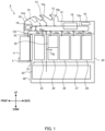
- FIG. 1 is a diagram illustrating an example of the configuration of the sheet processing apparatus according to the embodiment of the present invention.
- a sheet processing apparatus 1 is a banknote depositing and dispensing machine.
- the sheet processing apparatus 1 comprises an upper case 10 and a lower case 20.
- the upper case 10 comprises, in an upper part, an inlet section 12 in which banknotes to be fed into are disposed and an outlet section 13 in which banknotes to be fed out are disposed.
- the upper case 10 also comprises, inside thereof, a transport section 15 that transports banknotes, an identification section 16 that identifies banknotes, a control section 18 that controls other components of the sheet processing apparatus 1, and a temporary storage section 19 that temporarily stores banknotes.
- a second outlet section 14 may be provided adjacent to the outlet section 13. The configuration of the second outlet section 14 may be the same as that of the outlet section 13 or may be different from that of the outlet section 13.
- a feeding section (e.g., refer to FIG. 2 ) that feeds banknotes to the transport section 15 one by one at certain time intervals is provided.
- a stacking section (not illustrated) that stacks transported banknotes on one another is provided.
- the transport section 15 is a transport apparatus that transports banknotes at a certain transport speed.
- the transport section 15 comprises a belt mechanism and a roller mechanism for transporting banknotes.
- the transport section 15 comprises a loop transport path 15a that transports banknotes in a looped manner, and a first branch path 15b, a second branch path 15c, a third branch path 15d, fourth branch paths 15e, and a fifth branch path 15f that diverge from the loop transport path 15a.
- the first to fifth branch paths 15b to 15f may be regarded as part of the loop transport path 15a.
- the first to fifth branch paths 15b to 15f connect the loop transport path 15a to the inlet section 12, the outlet section 13, the temporary storage section 19, a first storage 21 and a second storage 30, which will be described later, and a detachable storage section 4, which will be described later, respectively.
- Diverters (not illustrated) for distributing banknotes are provided at connections between the first to fifth branch paths 15b to 15f and the loop transport path 15a.
- another branch path that connects the loop transport path 15a to the second outlet section 14 may also be provided.
- the identification section 16 is an identification apparatus that reads information on banknotes and that identifies the banknotes.
- the identification section 16 comprises a sensor such as an image sensor, an optical sensor, or a magnetic sensor and identifies banknote information regarding banknotes transported by the transport section 15, such as authenticity, denomination, fitness, and serial numbers.
- a serial number is a unique number given to each banknote and is, for example, a 10-digit character string comprising alphabets and numbers.
- the identification section 16 identifies 10 characters of each serial number.
- the temporary storage section 19 is a storage apparatus that temporarily stores banknotes.
- the temporary storage section 19 can take in and store banknotes one by one and feed out the stored banknotes one by one.
- the temporary storage section 19 is, for example, a storage section of a winding type, in which banknotes are wound around a rotating body.
- the temporary storage section 19 may be a storage section of a stacking type, in which banknotes are stacked on one another.
- the control section 18 is a control apparatus comprising a processing section such as a CPU and a storage section such as a memory.
- the control section 18 controls, through the transport section 15, the components of the sheet processing apparatus 1 and the detachable storage section 4 such that banknotes are transported between the inlet section 12, the outlet section 13, the temporary storage section 19, the first storage 21 and the second storage 30, which will be described later, and the detachable storage section 4, which will be described later.
- the lower case 20 comprises the first storage 21 and the second storage 30, which is provided under the first storage 21.
- the first storage 21 is, for example, a safe.
- a lockable storage door 22 is provided on a front surface of the first storage 21.
- a first storage section 23, a second storage section 24, a third storage section 25, which is provided over the second storage section 24, a fourth storage section 26, a fifth storage section 27, and a sixth storage section 28 are provided in this order from the front to the back.
- One of the fourth branch paths 15e that extends from the loop transport path 15a toward the second storage 30 is disposed between the first storage section 23 and the second and third storage section 24 and 25.
- the fourth branch paths 15e that diverge from the loop transport path 15a are connected to the first storage section 23 and the third to sixth storage sections 25 to 28.
- the first to sixth storage sections 23 to 28 are storage sections of the stacking type, in which banknotes are stacked on one another.
- the first to sixth storage sections 23 to 28 may be storage sections of the winding type, in which banknotes are wound around a rotating body. Banknotes sorted in accordance with results of identification performed by the identification section 16 are stored in the first to sixth storage sections 23 to 28.
- a sensor (not illustrated) that detects passing banknotes is provided at an entrance of each of the first to sixth storage sections 23 to 28.
- the sensor is an optical sensor comprising a light emission section that emits light such as infrared light and a light reception section that receives light emitted from the light emission section. Any type of sensor may be used insofar as the sensor can detect storage of banknotes in a corresponding storage section.
- the second storage 30 is, for example, a safe.
- the second storage 30 comprises a collection section 33 inside thereof.
- the collection section 33 comprises a storage area inside thereof, and the storage area stores banknotes collected from among ones taken in from the inlet section 12 and ones stored in the first storage 21.
- the collection section 33 is connected to one of the fourth branch paths 15e that diverge from the loop transport path 15a.
- a collector collects the banknotes from the collection section 33.
- a collector removes the collection section 33 from the sheet processing apparatus 1 together with the banknotes.
- the lower case 20 comprises a mounting section 5 for mounting the detachable storage section 4 on a front outer surface of the first storage 21.
- the outer front surface of the first storage 21 refers to an outer front surface of the first storage 21 that can be accessed without unlocking the storage door 22, that is, more specifically, an outer front surface of the lower case 20 or a front surface of the storage door 22.
- the mounting section 5 comprises a fixing medium for fixing the detachable storage section 4 mounted on the mounting section 5.
- the fixing medium may comprise a locking apparatus.
- the mounting section 5 comprises a terminal (not illustrated) for supplying control signals from the control section 18 to the detachable storage section 4.
- the detachable storage section 4 comprises a terminal (not illustrated) connected to the terminal of the mounting section 5.
- the terminal of the detachable storage section 4 is directly or indirectly connected to the terminal of the mounting section 5.
- a storage area inside the detachable storage section 4 is connected to the fifth branch path 15f.
- the detachable storage section 4 is a storage section of the stacking type, in which banknotes are stacked on one another.
- the detachable storage section 4 may be a storage section of the winding type, in which banknotes are wound around a rotating body.
- the detachable storage section 4 comprises a driving mechanism (not illustrated), such as a motor, for taking in banknotes and discharging banknotes.
- a driving mechanism such as a motor
- the sheet processing apparatus 1 comprises the driving mechanism and transfers driving force to the detachable storage section 4 mounted on the mounting section 5.
- FIG. 2 is a diagram illustrating an example of the configuration of a feeding section 40 provided for the inlet section 12.
- the feeding section 40 comprises a stage 41, kicker rollers 42, feed rollers 43, gate rollers 44, transport rollers 45, a board 46, and banknote guides 47.
- the stage 41 is arranged in such a way as to connect to an entrance of the first branch path 15b.
- the stage 41 is a flat, plate-like member, for example, on which banknotes P1 are stacked on one another. A bottom one of the banknotes P1 stacked on the stage 41 comes into contact with a surface of the stage 41.
- the banknotes P1 stacked on the stage 41 are fed into the first branch path 15b one by one from the bottom to the top, for example, in accordance with a deposit operation performed by a user.
- the kicker rollers 42 are provided under the stage 41 and the board 46 such that part of the circumference thereof protrudes from the stage 41 and the board 46.
- the stage 41 and the board 46 are provided with openings for allowing the part of the circumference of the kicker rollers 42 to protrude.
- the kicker rollers 42 rotate clockwise in FIG. 2 .
- the kicker rollers 42 kick a bottom one of the banknotes P1 stacked on the stage 41 toward the first branch path 15b.
- the feed rollers 43 are provided near the entrance of the first branch path 15b (at a slightly deeper position in the first branch path 15b than the entrance).
- the feed rollers 43 are provided under the first branch path 15b and the board 46 such that part of the circumference thereof protrudes from the first branch path 15b and the board 46.
- the first branch path 15b and the board 46 are provided with openings for allowing the part of the circumference of the feed rollers 43 to protrude.
- the feed rollers 43 rotate clockwise in FIG. 2 .
- the feed rollers 43 feed a bottom banknote kicked by the kicker rollers 42 into the first branch path 15b.
- the gate rollers 44 face the feed rollers 43 from above the feed rollers 43.
- the circumference of the gate rollers 44 is in contact with the circumference of the feed rollers 43.
- the gate rollers 44 comprise a one-way clutch (not illustrated), for example, and can rotate clockwise in FIG. 2 . As a result, banknotes passing through gaps between the feed rollers 43 and the gate rollers 44 are fed into the first branch path 15b one by one.
- the transport rollers 45 are provided in the first branch path 15b.
- the transport rollers 45 feed banknotes fed from the feed rollers 43 into the loop transport path 15a.
- the board 46 is provided under the stage 41 and the entrance of the first branch path 15b.
- the board 46 is provided with coils that detect foreign objects such as pieces of metal.
- the board 46 is provided in contact with or immediately below the stage 41 in order to efficiently detect, with the coils, a foreign object on the stage 41 or near the entrance of the first branch path 15b.
- a surface of the board 46 is parallel to the surface of the stage 41.
- FIG. 3 is a diagram illustrating an example of arrangement of the rollers at a time when the feeding section 40 is viewed from above.
- the same rollers as in FIG. 2 are given the same reference numerals.
- the feeding section 40 comprises three kicker rollers 42 and six feed rollers 43.
- the number of kicker rollers 42 is not limited to three, and the number of feed rollers 43 is not limited to six.
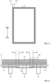
- FIG. 4 is a diagram illustrating an example of the configuration of the board 46. As illustrated in FIG. 4 , the board 46 comprises coils 51 to 53 and openings 54a to 54c and 55a to 55f.
- the board 46 is, for example, a multilayer board.
- the coils 51 to 53 are formed on a surface of the multilayer board or within a certain layer.
- the coils 51 to 53 illustrated in FIG. 4 are hatched for the purpose of distinction.
- FIG. 5 is a diagram illustrating an example of the configuration of the coil 51. As illustrated in FIG. 5 , the coil 51 is rectangular and spirally wound on a plane.
- a current or a voltage is supplied to terminals 51a and 51b of the coil 51 illustrated in FIG. 5 in accordance with control performed by the control section 18.
- the coil 51 generates a magnetic field from the current or the voltage supplied in accordance with the control performed by the control section 18.
- the coils 52 and 53 have the same shape as the coil 51 and are spirally wound on a plane.
- the number of turns is the same between the coils 51, 52, and 53.
- the number of turns of the coil 51 is four in FIG. 5 , but is not limited to this.
- FIG. 4 is referred to again.
- the coils 51 to 53 generate magnetic fields in accordance with the control (supply of a current or a voltage) performed by the control section 18.
- the coils 51 to 53 are wound spirally on planes in the board 46 in a rectangular manner.
- a magnetic field at the center of the coil 51 is generated in such a way as to penetrate through the board 46 vertically.
- Magnetic fields at the centers of the coils 52 and 53 are also generated in such a way as to penetrate through the board 46 vertically.
- the board 46 is provided in contact with or immediately below the stage 41.
- the surface of the board 46 is parallel to the surface of the stage 41.
- surfaces of the coils 51 to 53 formed in the board 46 are parallel to the surface of the stage 41, on which the banknotes P1 are stacked.
- the surfaces of the coils 51 to 53 formed in the board 46 are parallel to surfaces of the banknotes P1 stacked on the stage 41.
- the magnetic fields of the coils 51 to 53 therefore, are generated above the stage 41 near the entrance of the first branch path 15b, that is, in a space where the banknotes P1 are stacked (a space inside the inlet section 12 in which the banknotes P1 are taken).
- the magnetic fields of the coils 51 to 53 are generated in a space above the stage 41 near the first branch path 15b that a foreign object might enter.
- the coils 51 to 53 are arranged such that adjacent coils partially overlap with each other.
- the coils 51 to 53 are arranged side by side in a direction parallel to the surfaces of the banknotes P1 stacked on the feeding section 40 or the surface of the stage 41 on which the banknotes P1 are stacked and perpendicular to a feeding direction of the banknotes P1 (from "front" to "back” in FIG. 4 ).
- the adjacent coils 51 and 52 for example, partially overlap with each other in an area A1.
- the adjacent coils 52 and 53 partially overlap with each other in an area A2.
- the coils 51 to 53 are provided for the board 46 in correspondence with the arrangement of the kicker rollers 42.
- the coil 51 corresponds to the left kicker rollers 42 illustrated in FIG. 3 .
- the coil 52 corresponds to the central kicker rollers 42 illustrated in FIG. 3 .
- the coil 53 corresponds to the right kicker rollers 42 illustrated in FIG. 3 .
- the surfaces of the coils 51 to 53 may overlap the corresponding kicker rollers 42.
- the coils 51 to 53 may be provided in such a way as to surround the corresponding kicker rollers 42.
- the coils 51 to 53 may be provided for the board 46 such that the corresponding kicker rollers 42 are located at the centers of the coils 51 to 53.
- Two adjacent ones of the coils 51 to 53 may corresponding to the same feed roller 43.
- the coils 51 and 52 correspond to the second leftmost feed roller 43 illustrated in FIG. 3 .
- the coils 52 and 53 correspond to the second rightmost feed roller 43 illustrated in FIG.
- two adjacent coils may overlap one of the feed rollers 43.
- two adjacent coils may be provided in such a way as to surround one of the feed rollers 43.
- the openings 54a to 54c allow part of the circumference of the three kicker rollers 42 illustrated in FIG. 3 to protrude.
- the openings 55a to 55f allow part of the circumference of the six feed rollers 43 illustrated in FIG. 3 to protrude. Since the board 46 comprises openings 54a to 54c and 55a to 55f, the board 46 can be provided in contact with or immediately below the stage 41.
- the number of coils 51 to 53 provided for the board 46 is not limited to three.
- the number of coils may be two, or four or more.
- FIG. 6 is a diagram illustrating the feeding section 40 illustrated in FIG. 2 viewed from a direction indicated by an arrow A11.
- FIG. 6 illustrates the stage 41 and the kicker rollers 42 illustrated in FIG. 2 .
- FIG. 6 also illustrates the coils 51 to 53 illustrated in FIG. 4 .
- the surfaces of the coils 51 to 53 are parallel to the surface of the stage 41.
- the coils 51 to 53 are arranged (substantially) equidistantly from the space in which the banknotes P1 are stored.
- the space is defined by the feeding section 40, and the banknotes P1 that have been taken in are stacked in the space.
- the coils 51 to 53 are arranged substantially equidistantly from the surface of the stage 41 on which the banknotes P1 are stacked.
- a distance between the coil 51 and the bottom one of the banknotes P1 is the same as a distance between the coil 52 and the bottom one of the banknotes P1.
- the distance between the coil 52 and the bottom one of the banknotes P1 is the same as a distance between the coil 53 and the bottom one of the banknotes P1.
- the coils 51 to 53 illustrated in FIG. 6 are drawn thickly for the purpose of distinction, the actual coils 51 to 53 formed on the surface of the board 46 or in a layer in the board 46 are extremely thin.
- the coils 51 to 53 may be formed as wiring patterns on the board 46.
- the board 46, on which the coils 51 to 53 are formed is parallel to the surface of the stage 41, on which the banknotes P1 are stacked.
- the board 46, on which the coils 51 to 53 are formed is parallel to the banknotes P1 stacked on the stage 41.
- FIG. 7 is a diagram illustrating an example of the configuration of a foreign object detection control system.
- FIG. 7 illustrates the control section 18 illustrated in FIG. 1 and the board 46 illustrated in FIG. 4 .
- the shape of the board 46 illustrated in FIG. 7 is partly different from that of the board 46 illustrated in FIG. 4 .
- the foreign object detection control system comprises the control section 18, a detection control section 70, and the board 46.
- the control section 18 comprises a CPU 61, a field-programmable gate array (FPGA) 62, and a memory 63.
- the CPU 61 controls the entirety of the sheet processing apparatus 1.
- the CPU 61 determines whether there is a foreign object in the feeding section 40 (entry of a foreign object) on the basis of signals (data) output from the detection control section 70.
- the FPGA 62 controls communication of data between the CPU 61 and the detection control section 70.
- the FPGA 62 may perform part of the control supposed to be performed by the CPU 61 on the board 46.
- the FPGA 62 may turn on and off a switching circuit 72 instead of the CPU 61.
- the memory 63 stores a program for the CPU 61 to operate.
- the memory 63 also stores data used by the CPU 61 to perform processing and control the other components.
- the detection control section 70 comprises a detection control integrated circuit (IC) 71 and the switching circuit 72.
- the detection control IC 71 comprises driving conversion sections 71a to 71c.
- the driving conversion sections 71a to 71c output, to the switching circuit 72, currents or voltages for energizing the coils 51 to 53, respectively, in accordance with control (instruction) performed by the CPU 61.
- the currents or the voltages for energizing the coils 51 to 53 are alternating currents or voltages.
- the currents or the voltages for energizing the coils 51 to 53 are sine-wave currents or voltages. Amplitudes and frequencies of the currents or the voltages for energizing the coils 51 to 53 are (substantially) the same. As described with reference to FIG. 5 , the number of turns is the same between the coils 51 to 53, and magnitudes of the magnetic fields generated by the coils 51 to 53 are the same.
- the driving conversion sections 71a to 71c monitor the currents flowing to the terminals (e.g., the terminals 51a and 51b illustrated in FIG. 5 ) of the coils 51 to 53 or the voltages between the terminals of the coils 51 to 53, respectively.
- the driving conversion sections 71a to 71c output amplitudes (or absolute values of amplitudes) of the currents or the voltages monitored thereby to the CPU 61 through the FPGA 62.
- the driving conversion sections 71a to 71c convert analog values of the currents or the voltages monitored thereby into digital values and output the digital values to the CPU 61 through the FPGA 62.
- the currents or the voltages for energizing the coils 51 to 53 will also be referred to as “energizing signals” hereinafter.
- the currents flowing to the terminals of the coils 51 to 53 or the voltages between the terminals of the coils 51 to 53 will also be referred to as “reception signals” hereinafter.
- the switching circuit 72 comprises switches 72a to 72c.
- the switches 72a to 72c turn on and off connections between the driving conversion sections 71a to 71c and the coils 51 to 53, respectively, in accordance with control performed by the CPU 61 through the FPGA 62.
- the switches 72a to 72c turn on, for example, the driving conversion sections 71a to 71c and the coils 51 to 53 are connected to each other.
- the switches 72a to 72c turn off, the connections between the driving conversion sections 71a to 71c and the coils 51 to 53 are disconnected from each other.
- the energizing signals output from the driving conversion sections 71a to 71c are input to the coils 51 to 53, respectively.
- the coils 51 to 53 generate magnetic fields from the input energizing signals. If there is a foreign object, such as a piece of metal, near the coils 51 to 53 and the magnetic fields of the coils 51 to 53 are affected, amplitudes of reception signals change from those when there is no foreign object near the coils 51 to 53.
- the driving conversion sections 71a to 71c monitor reception signals of the coils 51 to 53 and output amplitudes of the reception signals to the CPU 61 through the FPGA 62.
- the CPU 61 detects entry of a foreign object into the feeding section 40 on the basis of the amplitudes of the reception signals.
- the reception signals can be regarded as foreign object detection signals output from the coils 51 to 53.
- FIG. 8 is a timing chart illustrating an example of the operation of the foreign object detection control system illustrated in FIG. 7 .
- T1 in FIG. 8 indicates timings at which the banknotes P1 stacked on the stage 41 are fed into the first branch path 15b one by one.
- Time taken for a banknote to be fed into the first branch path 15b is denoted by t1 as indicated in FIG. 8 .
- t1 time taken for a banknote to be fed into the first branch path 15b
- one of the banknotes P1 stacked on the stage 41 is fed into the first branch path 15b in each period t1.
- ON for the switches 72a to 72c in FIG. 8 denotes timings at which the switches 72a to 72c turn on.
- the switches 72a to 72c are turned off during periods other than ones indicated by ON in FIG. 8 .
- D1 to D3 for the coils 51 to 53 in FIG. 8 denote timings at which energizing signals are input to the coils 51 to 53 and the driving conversion sections 71a to 71c output amplitudes of reception signals to the CPU 61, respectively.
- the CPU 61 controls the driving conversion sections 71a to 71c and outputs energizing signals from the driving conversion sections 71a to 71c. As a result, the energizing signals are input to the switches 72a to 72c.
- the CPU 61 After causing the driving conversion sections 71a to 71c to output the energizing signals, the CPU 61 turns on and off the switches 72a to 72c one by one within the period t1. As indicated by an arrow A31a in FIG. 8 , for example, the CPU 61 keeps the switch 72a turned on for a certain period of time and then turns off the switch 72a. As indicated by an arrow A31b, after turning off the switch 72a, the CPU 61 keeps the switch 72b turned on for a certain period of time and then turns off the switch 72b. As indicated by an arrow A31c, after turning off the switch 72b, the CPU 61 keeps the switch 72c turned on for a certain period of time and then turns off the switch 72c.
- the energizing signals are sequentially input to the coils 51 to 53 within the period t1.
- the coils 51 to 53 in turn sequentially generate magnetic fields within the period t1.
- the process for sequentially turning on and off the switches 72a to 72c may be performed by the FPGA 62, instead.
- the driving conversion sections 71a to 71c monitor reception signals of the coils 51 to 53 while the switches 72a to 72c remain turned on, respectively, and then output amplitudes of the reception signals to the CPU 61 through the FPGA 62.
- the driving conversion section 71a monitors a reception signal of the coil 51 and outputs an amplitude of the reception signal to the CPU 61 through the FPGA 62 in a period D1 indicated by an arrow A32a in FIG. 8 .
- the driving conversion section 71b monitors a reception signal of the coil 52 and outputs an amplitude of the reception signal to the CPU 61 through the FPGA 62 in a period D2 indicated by an arrow A32b in FIG. 8 .
- the driving conversion section 71c monitors a reception signal of the coil 53 and outputs an amplitude of the reception signal to the CPU 61 through the FPGA 62 in a period D3 indicated by an arrow A32c in FIG. 8 .
- the CPU 61 determines whether a foreign object has entered the feeding section 40 on the basis of the received amplitudes of the reception signals. For example, when the CPU 61 has obtained the amplitudes of the reception signals of the coils 51 to 53 in the periods D1 to D3 indicated by the arrows A31a to A31c in FIG. 8 , the CPU 61 determines, in a period t1 indicated by an arrow A33, whether a foreign object has entered the feeding section 40 on the basis of the amplitudes of the reception signals received in the periods D1 to D3 indicated by the arrows A31a to A31c in FIG. 8 . That is, after receiving amplitudes of reception signals of all the coils 51 to 53, the CPU 61 determines, in a period t1 in which a next banknote is to be fed, whether a foreign object has entered the feeding section 40.
- the amount of change in an amplitude of a reception signal caused by a foreign object such as a piece of metal, right above a wire (lead wire) of one of the coils 51 to 53 is smaller than the amount of change in an amplitude of a reception signal caused by a foreign object within an area surrounded by the wire of one of the coils 51 to 53.
- a broken line A21 in FIG. 6 indicates a position right above the wire of the coil 52. If there is a foreign object, such as a piece of metal, on the line A21, the amount of change in an amplitude of a reception signal of the coil 52 is usually small.
- the coils 51 and 52 partly overlap with each other as described above.
- a foreign object on the line A21 therefore, is located not only right above the wire of the coil 52 but also within an area surrounded by the wire of the coil 51.
- the amount of change in an amplitude of a reception signal caused by a foreign object on the line A21 is large in the coil 51.
- a broken line A22 in FIG. 6 indicates a position right above the wire of the coil 51. If there is a foreign object, such as a piece of metal, on the line A22, the amount of change in an amplitude of a reception signal of the coil 51 is usually small.
- the coils 51 and 52 partly overlap with each other as described above.
- a foreign object on the line A22 therefore, is located not only right above the wire of the coil 51 but also within an area surrounded by the wire of the coil 52.
- the amount of change in an amplitude of a reception signal caused by a foreign object on the line A22 is large in the coil 52.
- a broken line A23 in FIG. 6 indicates a position right above the wire of the coil 53.
- the amount of change in an amplitude of a reception signal caused by a foreign object on the line A23 is large in the coil 52.
- a broken line A24 in FIG. 6 indicates a position right above the wire of the coil 52.
- the amount of change in an amplitude of a reception signal caused by a foreign object on the line A24 is large in the coil 53.
- the coils 51 to 53 are thus provided for the board 46 such that adjacent ones of the coils 51 to 53 partly overlap with each other.
- the CPU 61 controls the switches 72a to 72c in such a way as to sequentially energize the coils 51 to 53. As a result, even if there is a foreign object right above the wire of one of the coils 51 to 53, another of the coils 51 to 53 outputs a reception signal whose amplitude has been significantly changed.
- the operations performed by the CPU 61 comprise an operation for obtaining reference values and an operation for making a determination as to a foreign object using the obtained reference values.
- the CPU 61 obtains amplitudes (reference values) of reception signals of the coils 51 to 53 at a time when there are no banknotes or foreign objects (clean state) in the feeding section 40. For example, the CPU 61 obtains, with the feeding section 40 in the clear state, the reference values for the coils 51 to 53 after the sheet processing apparatus 1 is turned on.
- the CPU 61 After the sheet processing apparatus 1 is turned on, for example, the CPU 61 outputs energizing signals to the coils 51 to 53 as indicated by D1 to D3 in FIG. 8 .
- the CPU 61 receives, through the FPGA 62, amplitudes (reference values) of reception signals output from the driving conversion sections 71a to 71c and stores the reference values in the memory 63.
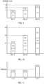
- FIG. 9 is a diagram illustrating an example of the reference values.
- r1, r2, and r3 denote the reference values for the coils 51, 52, and 53, respectively. That is, r1 to r3 in FIG. 9 denote amplitudes of reception signals of the coils 51 to 53 at a time when there are no banknotes or foreign objects in the feeding section 40.
- the reference values r1 to r3 are stored in the memory 63.
- the reference values (the amplitudes of the reception signals) output from the coils 51 to 53 comprise signal components that depend on a surrounding environment and signal components that do not depend on the surrounding environment.
- C1 to C3 in FIG. 9 denote signal components of the coils 51 to 53, respectively, that do not depend on the surrounding environment.
- Nr in FIG. 9 denotes signal components that depend on the surrounding environment of the coils 51 to 53. Nr varies depending on the surrounding environment of the coils 51 to 53.
- the coils 51 to 53 are configured such that the signal components of the coils 51 to 53 that depend on the surrounding environment become substantially the same.
- the signal components that depend on the surrounding environment become substantially the same by, for example, using the same material, the same shape, and the number of turns for the coils 51 to 53.
- the coils 51 to 53 may be coils whose signal components that depend on the surrounding environment are substantially the same with at least one of the material, the shape, and the number of turns different between the coils 51 to 53.
- the surrounding environment is, for example, surrounding temperature of the coils 51 to 53.
- the coils 51 to 53 may be coils at least whose signal components that depend on temperature are substantially the same, instead. A case where temperature, which is an example of the surrounding environment, affects the coils 51 to 53 will be described hereinafter.
- the CPU 61 determines whether a foreign object has entered the feeding section 40 in, for example, a deposit process using obtained reference values.
- the operations performed by the CPU 61 comprise, for example, a first operation for obtaining amplitudes of reception signals of the coils 51 to 53, a second operation for subtracting reference values obtained in advance from the amplitudes of the reception signals obtained in the first operation, and a third operation for determining whether a foreign object has entered the feeding section 40 on the basis of results of the subtraction performed in the second operation.
- the CPU 61 outputs energizing signals to the coils 51 to 53 once in each period t1.
- the coils 51 to 53 are sequentially energized once while a banknote P1 is being fed.
- the CPU 61 then receives (obtains) amplitudes of reception signals of the coils 51 to 53 at the timings indicated by D1 to D3 in FIG. 8 .
- FIG. 10 is a diagram illustrating an example of the amplitudes of the reception signals obtained by the CPU 61. It is assumed in FIG. 10 that a foreign object has entered an area A25 indicated by a dash-dot line in FIG. 6 .
- d1 to d3 denote the amplitudes of the reception signals of the coils 51 to 53, respectively.
- C1 to C3 denote signal components of the coils 51 to 53, respectively, that do not depend on temperature.
- C1 to C3 in FIG. 10 are the same as those in FIG. 9 .
- Nd denotes signal components of the coils 51 to 53 that depend on temperature.
- a surrounding temperature when the CPU 61 has obtained the amplitudes d1 to d3 of the reception signals is different from a surrounding temperature when the CPU 61 has obtained the reference values r1 to r3 illustrated in FIG. 9 are different from each other, and therefore Nd ⁇ Nr.
- E1 to E3 denote signal components of the coils 51 to 53, respectively, affected by the foreign object.
- the foreign object overlaps the coils 52 and 53 and is also located inside the wire of the coil 53, and therefore E2 ⁇ E3.
- the signal components of the coils 51 to 53 comprise signal components that do not depend on temperature, signal components that depend on temperature, and signal components affected by the foreign object.
- the CPU 61 Upon obtaining the amplitudes of the reception signals of the coils 51 to 53, the CPU 61 subtracts the reference values for the coils 51 to 53 from the obtained amplitudes of the corresponding reception signals of the coils 51 to 53.
- the CPU 61 subtracts the reference values for the coils 51 to 53 from the amplitudes of the reception signals of the coils 51 to 53, respectively.
- results (differential values) ⁇ 1 to ⁇ 3 of the subtraction of the reference values for the coils 51 to 53 from the corresponding amplitudes of the reception signals are as represented by the following equations 1 to 3.
- the CPU 61 Upon obtaining the results (hereinafter also referred to as "first differential values") of the subtraction of the reference values for the coils 51 to 53 from the amplitudes of the corresponding reception signals, the CPU 61 calculates absolute values of results (hereinafter also referred to as "second differential values") of subtraction of the obtained first differential values from each other. The CPU 61 then determines, on the basis of the calculated absolute values of the second differential values, whether a foreign object has entered the feeding section 40. If at least one of the absolute values of the second differential values exceeds a certain threshold, for example, the CPU 61 determines that a foreign object has entered the feeding section 40.
- the CPU 61 determines that a foreign object has entered the feeding section 40.
- FIG. 11 is a diagram illustrating an example of the determination made by the CPU 61 as to whether a foreign object has entered the feeding section 40.
- FIG. 11 illustrates the absolute values of the second differential values represented by equations 4 to 6. If at least one of the absolute values of the second differential values exceeds the certain threshold, the CPU 61 determines that a foreign object has entered the feeding section 40. In the example illustrated in FIG. 11 , ⁇ 31 exceeds the threshold. The CPU 61 determines that a foreign object has entered the feeding section 40.
- FIG. 12 is a flowchart illustrating an example of a process performed by the CPU 61 to obtain amplitudes of reception signals.
- the CPU 61 performs the process illustrated in the flowchart of FIG. 12 , for example, each time one of the banknotes P1 stacked on the stage 41 is fed into the first branch path 15b (in each period t1). It is assumed in the following description that the CPU 61 has obtained the reference values and stored the reference values in the memory 63. It is also assumed that the CPU 61 controls the driving conversion sections 71a to 71c in such a way as to output energizing signals to the switches 72a to 72c, respectively.
- the CPU 61 turns on the switch 72a (step S1). As a result, the energizing signal output from the driving conversion section 71a is input to the coil 51.
- the driving conversion section 71a outputs an amplitude of a reception signal of the coil 51 to the CPU 61 through the FPGA 62.
- the CPU 61 receives the amplitude of the reception signal of the coil 51 from the driving conversion section 71a through the FPGA 62 (step S2).
- the CPU 61 stores the received amplitude of the reception signal of the coil 51 in, for example, the memory 63.
- the CPU 61 turns off the switch 72a and turns on the switch 72b (step S3).
- the energizing signal output from the driving conversion section 71b is input to the coil 52.
- the driving conversion section 71b outputs an amplitude of a reception signal of the coil 52 to the CPU 61 through the FPGA 62.
- the CPU 61 receives the amplitude of the reception signal of the coil 52 from the driving conversion section 71b through the FPGA 62 (step S4).
- the CPU 61 stores the received amplitude of the reception signal of the coil 52 in, for example, the memory 63.
- the CPU 61 turns off the switch 72b and turns on the switch 72c (step S5).
- the energizing signal output from the driving conversion section 71c is input to the coil 53.
- the driving conversion section 71c outputs an amplitude of a reception signal of the coil 53 to the CPU 61 through the FPGA 62.
- the CPU 61 receives the amplitude of the reception signal of the coil 53 from the driving conversion section 71c through the FPGA 62 (step S6).
- the CPU 61 stores the received amplitude of the reception signal of the coil 53 in, for example, the memory 63.
- the CPU 61 turns off the switch 72c (step S7), and ends the process illustrated in the flowchart.
- the CPU 61 After receiving the amplitudes of the reception signals of all the coils 51 to 53 in the period t1 (after storing the amplitudes of the reception signals in the memory 63), the CPU 61 determines, in the next period t1 on the basis of the amplitudes of the reception signals stored in the memory 63, whether a foreign object has entered the feeding section 40.
- FIG. 13 is a flowchart illustrating an example of a process performed by the CPU 61 to determine whether a foreign object has entered the feeding section 40.
- the CPU 61 performs the process illustrated in the flowchart of FIG. 13 , for example, each time one of the banknotes P1 stacked on the stage 41 is fed into the first branch path 15b (in each period t1).
- the CPU 61 obtains first differential values by subtracting reference values stored in the memory 63 from amplitudes of reception signals stored in the memory 63 (step S11). For example, the CPU 61 subtracts the reference values for the coils 51 to 53 stored in the memory 63 from the amplitudes of the reception signals of the coils 51 to 53, respectively, stored in the memory 63 (differential values ⁇ 1 to ⁇ 3 of the coils 51 to 53 are obtained as a result of the subtraction).
- the CPU 61 calculates second differential values (absolute values) by subtracting the first differential values from each other (step S12). For example, the CPU 61 obtains an absolute value ⁇ 12 of a result of subtraction of the differential value ⁇ 2 of the coil 52 from the differential value ⁇ 1 of the coil 51. The CPU 61 obtains an absolute value ⁇ 23 of a result of subtraction of the differential value ⁇ 3 of the coil 53 from the differential value ⁇ 2 of the coil 52. The CPU 61 obtains an absolute value ⁇ 31 of a result of subtraction of the differential value ⁇ 1 of the coil 51 from the differential value ⁇ 3 of the coil 53.
- the CPU 61 determines whether at least one of the second differential values exceeds a threshold (step S13). For example, the CPU 61 determines whether at least one of ⁇ 12, ⁇ 23, and ⁇ 31 exceeds the threshold. If determining that none of ⁇ 12, ⁇ 23, and ⁇ 31 exceeds the threshold (NO in S13), the CPU 61 ends the process illustrated in the flowchart. If determining that at least one of ⁇ 12, ⁇ 23, and ⁇ 31 exceeds the threshold (YES in S13), on the other hand, the CPU 61 stops rotation of the kicker rollers 42 (step S14). As a result, the foreign object is prevented from entering the first branch path 15b.
- the CPU 61 may perform the processes illustrated in the flowcharts of FIGS. 12 and 13 at least once. That is, before the banknotes P1 taken in the inlet section 12 are fed into the first branch path 15b, the CPU 61 may perform the processes illustrated in the flowcharts of FIGS. 12 and 13 at least once. As a result, the foreign object is prevented from entering the first branch path 15b.
- the CPU 61 may keep performing the processes illustrated in the processes of FIGS. 12 and 13 even while the banknotes P1 are being fed into the first branch path 15b. In this case, even if a foreign object enters the feeding section 40 while the banknotes P1 are being fed into the first branch path 15b, the foreign object is prevented from entering the first branch path 15b.
- the sheet processing apparatus 1 comprises the coils 51 to 53 that are provided in the feeding section 40, which feeds banknotes that have been taken in into a transport path, and that generate magnetic fields and the CPU 61 that determines whether a foreign object has entered the feeding section 40 on the basis of differential values between amplitudes of reception signals output from the coils 51 to 53.
- the coils 51 to 53 are foreign object detection coils that output different signals depending on whether there is a foreign object nearby.
- the sheet processing apparatus 1 improves the accuracy of detecting entry of a foreign object while suppressing an increase in the number of parts. For example, the sheet processing apparatus 1 can accurately determine whether a foreign object has entered the feeding section 40 regardless of an effect of a change in surrounding temperature without a temperature sensor, a reference coil, or the like.
- the sheet processing apparatus 1 is just an example of an apparatus on which the present invention is implemented.
- the present invention can also be widely implemented on sheet processing apparatuses comprising the feeding section 40 that feeds banknotes that have been taken in into a transport path.
- a feeding section on which the present invention is implemented is not limited to the above-described feeding section 40, and any feeding section comprising a function of feeding banknotes into a transport path one by one may be used.
- the CPU 61 may obtain reference values at another timing, instead.
- the CPU 61 may obtain reference values at a timing specified by a user.
- the reference values may be values stored in the memory 63 in advance, instead.
- the driving conversion sections 71a to 71c output amplitudes of reception signals of the coils 51 to 53 to the CPU 61 through the FPGA 62 in the above description, the driving conversion sections 71a to 71c may output frequencies of reception signals of the coils 51 to 53 to the CPU 61 through the FPGA 62, instead.
- the CPU 61 stores frequencies of reception signals of the coils 51 to 53 in the memory 63 as reference values.
- the CPU 61 subtracts the reference values for frequencies of the coils 51 to 53 from the frequencies of the reception signals of the coils 51 to 53 output from the driving conversion sections 71a to 71c (calculates first differential values).
- the CPU 61 then calculates differential values (second differential values) between the first differential values and determines whether a foreign object has entered the feeding section 40 on the basis of the calculated second differential values.
- the driving conversion sections 71a to 71c may output amplitudes and frequencies of reception signals of the coils 51 to 53 to the CPU 61 through the FPGA 62.
- the CPU 61 stores amplitudes and frequencies of reception signals of the coils 51 to 53 in the memory 63 as reference values.
- the CPU 61 subtracts the reference values for amplitudes of the coils 51 to 53 from the amplitudes of the reception signals of the coils 51 to 53 output from the driving conversion sections 71a to 71c (calculates first amplitude differential values).
- the CPU 61 also subtracts the reference values for frequencies of the coils 51 to 53 from the frequencies of the reception signals of the coils 51 to 53 output from the driving conversion sections 71a to 71c (calculates first frequency differential values).
- the CPU 61 then calculates differential values (second amplitude differential values) between the first amplitude differential values.
- the CPU 61 also calculates differential values (second frequency differential values) between the first frequency differential values. If at least one of the second amplitude differential values exceeds a threshold and at least one of the second frequency differential values exceeds a threshold, the CPU 61 determines that a foreign object has entered the feeding section 40.
- a position at which the board 46 is provided is not limited to this.
- the board 46 may be provided on a back surface (a position indicated by a broken line A41 in FIG. 2 ) of the banknote guides 47 illustrated in FIG. 2 , instead.
- banknotes are set flat in the sheet processing apparatus 1 in the above description, the present invention can also be implemented on sheet processing apparatuses in which banknotes are set upright.
- FIG. 14 is a diagram illustrating an example of the configuration of a sheet processing apparatus 100 in which banknotes are set upright.
- the sheet processing apparatus 100 comprises kicker rollers 101, feed rollers 102, gate rollers 103, a transport path 104, a stage 105, a fixed guide 106, and a movable guide 107.
- FIG. 14 illustrates banknotes P101 set upright. Pushing members (not illustrated), such as springs, of the movable guide 107 push the upright banknotes P101 toward the fixed guide 106.
- the board 46 may be provided under the stage 105 (a position A101 indicated by a broken line in FIG. 14 ). Alternatively, the board 46 may be provided on a back side (a position A102 indicated by a broken line in FIG. 14 ) of the fixed guide 106. Alternatively, the board 46 may be provided on a back side (a position A103 indicated by a broken line in FIG. 14 ) of the movable guide 107.
- the sheet processing apparatus 100 also comprises the control section 18 illustrated in FIG. 7 and the detection control section 70 (not illustrated).
- the foreign object detection control system can thus be used for the sheet processing apparatus 100 in which banknotes are set upright.
- the configuration of the foreign object detection control system is not limited to the example illustrated in FIG. 7 .
- the FPGA 62, the detection control IC 71, and the switching circuit 72 may be achieved by a single chip.
- the CPU 61 may comprise the functions of the FPGA 62, the detection control IC 71, and the switching circuit 72.
- the detection control section 70 may be mounted on the board 46, instead.
- the driving conversion sections 71a to 71c may output energizing signals such that adjacent ones of the coils 51 to 53 generate opposite magnetic fields.
- the driving conversion sections 71a to 71c may output energizing signals such that the coil 51 generates a magnetic field directed to a nearer side of the page of FIG. 4 , the coil 52 generates a magnetic field directed to a deeper side of the page of FIG. 4 , and the coil 53 generates a magnetic field directed to the nearer side of the page of FIG. 4 .
- the coils 51 to 53 are sequentially energized, the coils 51 to 53 are hardly affected by magnetic fields of coils that have been previously energized.
- the coils 51 to 53 generate opposite magnetic fields even if energizing signals of the same phase are input to the adjacent ones of the coils 51 to 53.
- the operation for calculating the first differential values may be omitted, and the second differential values may be results of subtraction of amplitudes of reception signals of the coils 51 to 53 from each other, instead.
- C1 to C3 are signal components of the coils 51 to 53 that do not depend on temperature and are unique to the coils 51 to 53, respectively.
- C1 - C2, C2 - C3, and C3 - C1 can be identified.
- the threshold for the differential value between the coils 51 and 52 is a value that takes into consideration C1 - C2
- the threshold for the differential value between the coils 52 and 53 is a value that takes into consideration C2 - C3
- the threshold for the differential value between the coils 53 and 51 is a value that takes into consideration C3 - C1.
- the control section 18 can then determine whether a foreign object has entered the feeding section 40 by comparing the thresholds (the thresholds that take into consideration C1 - C2, C2 - C3, and C3 - C1) and the absolute values represented by equations 7 to 9, respectively. Whether a foreign object has entered a feeding section can thus be determined on the basis of differential values between signals output from a plurality of coils.
- the sheet processing apparatus on which the present invention is implemented comprises a plurality of coils that are provided in a feeding section which feeds a sheet that has been taken in into a transport path and that generate magnetic fields and a control section that determines, on a basis of differential values between signals output from the plurality of coils, whether a foreign object has entered the feeding section.
- the control section causes the plurality of coils to sequentially generate the magnetic fields one by one and detects the signals output from the plurality of coils while the coils are generating the magnetic fields.
- the present invention is not limited to this mode.
- the coils 51 to 53 may be energized a plurality of times while the feeding section 40 is feeding out one of the banknotes P1.
- the control section 18 performs, a plurality of times, a process for sequentially energizing the coils 51 to 53 and detecting signals output from the coils 51 to 53 while the coils 51 to 53 are generating magnetic fields.
- the control section 18 performs a process for sequentially energizing the coils 51 to 53 a plurality of times and detecting, the plurality of times, signals output from the coils 51 to 53 while the coils 51 to 53 are generating magnetic fields.
- the control section 18 determines, using all the signals detected in the process in which the coils 51 to 53 have been energized a plurality of times, whether a foreign object has entered the feeding section 40. For example, the control section 18 determines, using the detected signals, whether a foreign object has entered the feeding section 40. If the number of signals indicating that the control section 18 has determined that a foreign object has entered the feeding section 40 is larger than a certain value, the control section 18 confirms the result of the determination that a foreign object has entered the feeding section 40.
- the control section 18 may confirm the result of the determination that a foreign object has entered the feeding section 40. In this case, even if the coils 51 to 53 temporarily operate abnormally, the control section 18 can accurately determine whether a foreign object has entered the feeding section 40.
- the coils 51 to 53 might output abnormal signals. By also detecting signals before and after the occurrence of static electricity, however, an incorrect result of a determination based only on the abnormal signals can be avoided.
Landscapes
- Physics & Mathematics (AREA)
- General Physics & Mathematics (AREA)
- Engineering & Computer Science (AREA)
- Life Sciences & Earth Sciences (AREA)
- Remote Sensing (AREA)
- Environmental & Geological Engineering (AREA)
- Electromagnetism (AREA)
- Geology (AREA)
- General Life Sciences & Earth Sciences (AREA)
- Geophysics (AREA)
- Mechanical Engineering (AREA)
- Inspection Of Paper Currency And Valuable Securities (AREA)
- Controlling Sheets Or Webs (AREA)
Claims (13)
- Ein Blattverarbeitungsgerät, das Folgendes umfasst:mehrere Spulen (5 bis 53), die in einem Zuführabschnitt (40) vorgesehen sind, der dazu eingerichtet ist, ein Blatt, das eingezogen wurde, in einen Transportweg zu führen, und die dazu eingerichtet sind, Magnetfelder zu erzeugen;einen Steuerabschnitt (19), der dazu eingerichtet ist, auf der Grundlage von Differenzwerten zwischen von den mehreren Spulen ausgegebenen Signalen zu bestimmen, ob ein Fremdkörper in den Zuführabschnitt gelangt ist; undmehrere Auswurfrollen (42), die dazu eingerichtet sind, das Blatt in Richtung eines Torabschnitts auszuwerfen, wobeidie mehreren Spulen Fremdkörper-Erfassungsspulen sind, die unterschiedliche Signale ausgeben, je nachdem, ob sich ein Fremdkörper in der Nähe befindet, dadurch gekennzeichnet, dassdie mehreren Spulen entsprechend der Anordnung der mehreren Auswurfrollen angeordnet sind und so angeordnet sind, dass sie die mehreren Auswurfrollen umgeben, so dass ein Teil jeder der Auswurfrollen in eine von den mehreren Spulen gebildete Öffnung eindringt.
- Das Blattverarbeitungsgerät nach Anspruch 1,wobei ein Referenzwert im Voraus für jede der mehreren Spulen eingestellt wird undwobei der Steuerabschnitt dazu eingerichtet ist, erste Differenzwerte zwischen den von den mehreren Spulen ausgegebenen Signalen und den Referenzwerten für die mehreren Spulen und zweite Differenzwerte zwischen den ersten Differenzwerten für die mehreren Spulen zu berechnen und auf der Grundlage der zweiten Differenzwerte zu bestimmen, ob ein Fremdkörper in den Zuführabschnitt gelangt ist.
- Das Blattverarbeitungsgerät nach Anspruch 2,
wobei die Referenzwerte Werte von Signalen sind, die von den mehreren Spulen ausgegeben werden, wenn kein Fremdkörper in den Zuführabschnitt gelangt ist. - Das Blattverarbeitungsgerät nach Anspruch 3,
wobei die Referenzwerte Werte sind, die zu einem bestimmten Zeitpunkt gemessen werden. - Das Blattverarbeitungsgerät nach einem der Ansprüche 1 bis 4,
wobei die Oberflächen der mehreren Spulen parallel zu einer Oberfläche des Blattes sind und die mehreren Spulen in einer Richtung senkrecht zu einer Richtung angeordnet sind, in der das Blatt zugeführt wird. - Das Blattverarbeitungsgerät nach einem der Ansprüche 1 bis 5,
wobei die mehreren Spulen äquidistant von einem Raum innerhalb des Zuführabschnitts angeordnet sind, in dem das Blatt gespeichert ist. - Das Blattverarbeitungsgerät nach einem der Ansprüche 1 bis 6,
wobei benachbarte der mehreren Spulen einander teilweise überlappen. - Das Blattverarbeitungsgerät nach einem der Ansprüche 1 bis 7,
wobei die mehreren Spulen dazu eingerichtet sind, die Magnetfelder sequenziell einzeln zu erzeugen. - Das Blattverarbeitungsgerät nach einem der Ansprüche 1 bis 8,
wobei die mehreren Spulen jeweils dazu eingerichtet sind, die Magnetfelder zu unterschiedlichen Zeitpunkten zu erzeugen, so dass zu jedem Zeitpunkt nur eine der mehreren Spulen das Magnetfeld erzeugt. - Das Blattverarbeitungsgerät nach einem der Ansprüche 1 bis 9,
wobei benachbarte der mehreren Spulen dazu eingerichtet sind, entgegengesetzte Magnetfelder zu erzeugen. - Das Blattverarbeitungsgerät nach einem der Ansprüche 1 bis 10,
wobei die Größen der von den mehreren Spulen erzeugten Magnetfelder gleich sind. - Das Blattverarbeitungsgerät nach einem der Ansprüche 1 bis 11,
wobei die Formen und die Anzahl der Windungen der mehreren Spulen gleich sind. - Ein Verfahren zur Bestimmung des Eindringens eines Fremdkörpers unter Verwendung der Blattverarbeitungsvorrichtung nach einem der Ansprüche 1 bis 12, umfassend:das Erzeugen von Magnetfeldern mit mehreren Spulen (51-53), die in einem Zuführabschnitt (40) vorgesehen sind, der ein Blatt zuführt, das in einen Transportweg aufgenommen worden ist;das Berechnen von Differenzwerten zwischen Ausgangssignalen von mehreren Spulen; unddas Bestimmen auf der Grundlage der Differenzwerte, ob ein Fremdkörper in den Zuführabschnitt gelangt ist, wobeidie mehreren Spulen Fremdkörper-Erfassungsspulen sind, die unterschiedliche Signale ausgeben, je nachdem, ob sich ein Fremdkörper in der Nähe befindet,wobei während der Zuführabschnitt (40) Blätter ausgibt, der Steuerabschnitt (18) einen Prozess zum mehrmaligen sequenziellen Bestromen der Spulen (51-53) und zum mehrmaligen Erfassen von Signalen, die von den Spulen (51-53) ausgegeben werden, während die Spulen (51-53) Magnetfelder erzeugen, durchführt, undwobei der Steuerabschnitt (18) unter Verwendung aller Signale, die in dem Prozess, in dem die Spulen (51-53) mehrere Male bestromt wurden, erfasst wurden, bestimmt, ob ein Fremdkörper in den Zuführabschnitt (40) gelangt ist.
Applications Claiming Priority (1)
| Application Number | Priority Date | Filing Date | Title |
|---|---|---|---|
| JP2019075394A JP2020173631A (ja) | 2019-04-11 | 2019-04-11 | 紙葉類処理装置および異物混入判定方法 |
Publications (2)
| Publication Number | Publication Date |
|---|---|
| EP3723055A1 EP3723055A1 (de) | 2020-10-14 |
| EP3723055B1 true EP3723055B1 (de) | 2025-06-18 |
Family
ID=70189686
Family Applications (1)
| Application Number | Title | Priority Date | Filing Date |
|---|---|---|---|
| EP20167951.1A Active EP3723055B1 (de) | 2019-04-11 | 2020-04-03 | Blattverarbeitungsgerät und verfahren zur bestimmung des eintritts von fremdkörpern |
Country Status (4)
| Country | Link |
|---|---|
| US (1) | US11767187B2 (de) |
| EP (1) | EP3723055B1 (de) |
| JP (1) | JP2020173631A (de) |
| AU (1) | AU2020202465A1 (de) |
Families Citing this family (1)
| Publication number | Priority date | Publication date | Assignee | Title |
|---|---|---|---|---|
| JP2021026606A (ja) * | 2019-08-07 | 2021-02-22 | グローリー株式会社 | 紙葉類処理装置および異物検出方法 |
Citations (1)
| Publication number | Priority date | Publication date | Assignee | Title |
|---|---|---|---|---|
| US7055738B2 (en) * | 2001-02-05 | 2006-06-06 | Wincor Nixdorf International Gmbh | Device for accepting banknotes |
Family Cites Families (15)
| Publication number | Priority date | Publication date | Assignee | Title |
|---|---|---|---|---|
| US4433528A (en) * | 1982-08-30 | 1984-02-28 | Sperry Corporation | Metal detector apparatus |
| US4883264A (en) * | 1987-11-02 | 1989-11-28 | Laurel Bank Machines Co., Ltd. | Bill disbursing system |
| JPH0776993B2 (ja) * | 1987-11-02 | 1995-08-16 | ローレルバンクマシン株式会社 | 紙葉類処理機 |
| JP3199605B2 (ja) | 1995-06-07 | 2001-08-20 | ローレルバンクマシン株式会社 | 紙幣入金機における混入金属検知装置 |
| JP2001084426A (ja) | 1999-09-17 | 2001-03-30 | Canon Electronics Inc | 金属片残留検知装置 |
| JP2004028708A (ja) * | 2002-06-24 | 2004-01-29 | Omron Corp | 磁界センサおよび磁界センサを備えた紙葉類搬送装置 |
| JP2008203240A (ja) * | 2007-01-25 | 2008-09-04 | Nippon Soken Inc | 電磁インピーダンスセンサとそれを用いた乗員保護システム |
| WO2009040941A1 (ja) | 2007-09-28 | 2009-04-02 | Glory Ltd. | 紙葉類処理装置、紙葉類取込ユニットおよび紙葉類取込方法 |
| JP2013192391A (ja) * | 2012-03-14 | 2013-09-26 | Sony Corp | 検知装置、受電装置、送電装置及び非接触給電システム |
| JP2014025771A (ja) | 2012-07-26 | 2014-02-06 | Nidec Sankyo Corp | 磁気センサ装置 |
| KR101554254B1 (ko) | 2012-12-26 | 2015-09-18 | 노틸러스효성 주식회사 | 금속감지장치 및 이를 이용한 금융자동화기기에서의 금속감지방법 |
| JP2014190887A (ja) | 2013-03-28 | 2014-10-06 | Nidec Sankyo Corp | 異物検出装置および異物検出方法 |
| JP6688476B2 (ja) * | 2015-07-10 | 2020-04-28 | 株式会社リコー | シート材厚み検出装置、シート材異常検出装置、シート材供給装置及び画像形成装置 |
| JP6742438B2 (ja) * | 2016-07-06 | 2020-08-19 | ヒューレット−パッカード デベロップメント カンパニー エル.ピー.Hewlett‐Packard Development Company, L.P. | 三角形状のインダクタコイルを有する検出器 |
| JP6741506B2 (ja) * | 2016-07-15 | 2020-08-19 | グローリー株式会社 | 貨幣処理装置及び金属検知装置 |
-
2019
- 2019-04-11 JP JP2019075394A patent/JP2020173631A/ja active Pending
-
2020
- 2020-04-02 US US16/838,032 patent/US11767187B2/en active Active
- 2020-04-03 EP EP20167951.1A patent/EP3723055B1/de active Active
- 2020-04-09 AU AU2020202465A patent/AU2020202465A1/en not_active Abandoned
Patent Citations (1)
| Publication number | Priority date | Publication date | Assignee | Title |
|---|---|---|---|---|
| US7055738B2 (en) * | 2001-02-05 | 2006-06-06 | Wincor Nixdorf International Gmbh | Device for accepting banknotes |
Also Published As
| Publication number | Publication date |
|---|---|
| US11767187B2 (en) | 2023-09-26 |
| JP2020173631A (ja) | 2020-10-22 |
| US20200324989A1 (en) | 2020-10-15 |
| AU2020202465A1 (en) | 2020-10-29 |
| EP3723055A1 (de) | 2020-10-14 |
Similar Documents
| Publication | Publication Date | Title |
|---|---|---|
| CN103229216B (zh) | 纸币处理装置以及该纸币处理装置中使用的交接单元 | |
| EP2782076B1 (de) | Blattverarbeitungsverfahren, Blattverarbeitungsvorrichtung und Blattverarbeitungssystem | |
| CN102760325B (zh) | 纸币处理装置及纸币输送状态检测方法 | |
| EP3723055B1 (de) | Blattverarbeitungsgerät und verfahren zur bestimmung des eintritts von fremdkörpern | |
| JPWO2012127525A1 (ja) | 紙幣処理装置 | |
| JP2009211501A (ja) | 硬貨識別装置 | |
| EP0280147A2 (de) | Papierblätterverarbeitungsvorrichtung | |
| JP5336900B2 (ja) | 硬貨識別装置及び硬貨識別方法 | |
| JP2012160122A (ja) | 硬貨出金装置 | |
| US9359165B2 (en) | Sheet processing apparatus | |
| JP2018144989A (ja) | 紙葉類処理装置 | |
| KR100984760B1 (ko) | 지폐계수기 및 지폐정사기의 테이프권 검지장치 | |
| JP6244922B2 (ja) | 現金処理装置 | |
| JP5277443B2 (ja) | 紙幣処理装置 | |
| EP4012398A1 (de) | Vorrichtung zur handhabung von papierbögen und verfahren zur detektion von fremdkörpern | |
| US9153087B2 (en) | Coin processing device | |
| US7242486B2 (en) | Note skew detector | |
| GB2064101A (en) | Apparatus for identifying Sheet-like Printed Matters | |
| JPS622392A (ja) | 紙幣鑑別装置 | |
| JPH0373091A (ja) | 硬貨判別計数装置 | |
| JP2012053774A (ja) | 紙幣識別装置 | |
| JP4403797B2 (ja) | 紙幣識別装置 | |
| JP2008027356A (ja) | 紙幣識別装置 | |
| JP2025131183A (ja) | 紙幣搬送装置、及びそれを備えた釣銭機 | |
| JP5245309B2 (ja) | 硬貨識別装置 |
Legal Events
| Date | Code | Title | Description |
|---|---|---|---|
| PUAI | Public reference made under article 153(3) epc to a published international application that has entered the european phase |
Free format text: ORIGINAL CODE: 0009012 |
|
| STAA | Information on the status of an ep patent application or granted ep patent |
Free format text: STATUS: REQUEST FOR EXAMINATION WAS MADE |
|
| 17P | Request for examination filed |
Effective date: 20200403 |
|
| AK | Designated contracting states |
Kind code of ref document: A1 Designated state(s): AL AT BE BG CH CY CZ DE DK EE ES FI FR GB GR HR HU IE IS IT LI LT LU LV MC MK MT NL NO PL PT RO RS SE SI SK SM TR |
|
| AX | Request for extension of the european patent |
Extension state: BA ME |
|
| RBV | Designated contracting states (corrected) |
Designated state(s): AL AT BE BG CH CY CZ DE DK EE ES FI FR GB GR HR HU IE IS IT LI LT LU LV MC MK MT NL NO PL PT RO RS SE SI SK SM TR |
|
| STAA | Information on the status of an ep patent application or granted ep patent |
Free format text: STATUS: EXAMINATION IS IN PROGRESS |
|
| 17Q | First examination report despatched |
Effective date: 20230222 |
|
| P01 | Opt-out of the competence of the unified patent court (upc) registered |
Effective date: 20230531 |
|
| GRAP | Despatch of communication of intention to grant a patent |
Free format text: ORIGINAL CODE: EPIDOSNIGR1 |
|
| STAA | Information on the status of an ep patent application or granted ep patent |
Free format text: STATUS: GRANT OF PATENT IS INTENDED |
|
| INTG | Intention to grant announced |
Effective date: 20250205 |
|
| RIN1 | Information on inventor provided before grant (corrected) |
Inventor name: GOKURAKUJI, TAIKI |
|
| GRAS | Grant fee paid |
Free format text: ORIGINAL CODE: EPIDOSNIGR3 |
|
| GRAA | (expected) grant |
Free format text: ORIGINAL CODE: 0009210 |
|
| STAA | Information on the status of an ep patent application or granted ep patent |
Free format text: STATUS: THE PATENT HAS BEEN GRANTED |
|
| AK | Designated contracting states |
Kind code of ref document: B1 Designated state(s): AL AT BE BG CH CY CZ DE DK EE ES FI FR GB GR HR HU IE IS IT LI LT LU LV MC MK MT NL NO PL PT RO RS SE SI SK SM TR |
|
| REG | Reference to a national code |
Ref country code: GB Ref legal event code: FG4D |
|
| REG | Reference to a national code |
Ref country code: CH Ref legal event code: EP |
|
| REG | Reference to a national code |
Ref country code: DE Ref legal event code: R096 Ref document number: 602020052821 Country of ref document: DE |
|
| REG | Reference to a national code |
Ref country code: CH Ref legal event code: EP |
|
| REG | Reference to a national code |
Ref country code: IE Ref legal event code: FG4D |
|
| PG25 | Lapsed in a contracting state [announced via postgrant information from national office to epo] |
Ref country code: FI Free format text: LAPSE BECAUSE OF FAILURE TO SUBMIT A TRANSLATION OF THE DESCRIPTION OR TO PAY THE FEE WITHIN THE PRESCRIBED TIME-LIMIT Effective date: 20250618 |
|
| REG | Reference to a national code |
Ref country code: LT Ref legal event code: MG9D |
|
| PG25 | Lapsed in a contracting state [announced via postgrant information from national office to epo] |
Ref country code: GR Free format text: LAPSE BECAUSE OF FAILURE TO SUBMIT A TRANSLATION OF THE DESCRIPTION OR TO PAY THE FEE WITHIN THE PRESCRIBED TIME-LIMIT Effective date: 20250919 Ref country code: NO Free format text: LAPSE BECAUSE OF FAILURE TO SUBMIT A TRANSLATION OF THE DESCRIPTION OR TO PAY THE FEE WITHIN THE PRESCRIBED TIME-LIMIT Effective date: 20250918 |
|
| PG25 | Lapsed in a contracting state [announced via postgrant information from national office to epo] |
Ref country code: BG Free format text: LAPSE BECAUSE OF FAILURE TO SUBMIT A TRANSLATION OF THE DESCRIPTION OR TO PAY THE FEE WITHIN THE PRESCRIBED TIME-LIMIT Effective date: 20250618 |
|
| PG25 | Lapsed in a contracting state [announced via postgrant information from national office to epo] |
Ref country code: HR Free format text: LAPSE BECAUSE OF FAILURE TO SUBMIT A TRANSLATION OF THE DESCRIPTION OR TO PAY THE FEE WITHIN THE PRESCRIBED TIME-LIMIT Effective date: 20250618 |
|
| PG25 | Lapsed in a contracting state [announced via postgrant information from national office to epo] |
Ref country code: RS Free format text: LAPSE BECAUSE OF FAILURE TO SUBMIT A TRANSLATION OF THE DESCRIPTION OR TO PAY THE FEE WITHIN THE PRESCRIBED TIME-LIMIT Effective date: 20250918 |
|
| REG | Reference to a national code |
Ref country code: NL Ref legal event code: MP Effective date: 20250618 |
|
| PG25 | Lapsed in a contracting state [announced via postgrant information from national office to epo] |
Ref country code: LV Free format text: LAPSE BECAUSE OF FAILURE TO SUBMIT A TRANSLATION OF THE DESCRIPTION OR TO PAY THE FEE WITHIN THE PRESCRIBED TIME-LIMIT Effective date: 20250618 |
|
| PG25 | Lapsed in a contracting state [announced via postgrant information from national office to epo] |
Ref country code: NL Free format text: LAPSE BECAUSE OF FAILURE TO SUBMIT A TRANSLATION OF THE DESCRIPTION OR TO PAY THE FEE WITHIN THE PRESCRIBED TIME-LIMIT Effective date: 20250618 |
|
| PG25 | Lapsed in a contracting state [announced via postgrant information from national office to epo] |
Ref country code: PT Free format text: LAPSE BECAUSE OF FAILURE TO SUBMIT A TRANSLATION OF THE DESCRIPTION OR TO PAY THE FEE WITHIN THE PRESCRIBED TIME-LIMIT Effective date: 20251020 |
|
| REG | Reference to a national code |
Ref country code: AT Ref legal event code: MK05 Ref document number: 1804947 Country of ref document: AT Kind code of ref document: T Effective date: 20250618 |
|
| PG25 | Lapsed in a contracting state [announced via postgrant information from national office to epo] |
Ref country code: IS Free format text: LAPSE BECAUSE OF FAILURE TO SUBMIT A TRANSLATION OF THE DESCRIPTION OR TO PAY THE FEE WITHIN THE PRESCRIBED TIME-LIMIT Effective date: 20251018 |
|
| PG25 | Lapsed in a contracting state [announced via postgrant information from national office to epo] |
Ref country code: SM Free format text: LAPSE BECAUSE OF FAILURE TO SUBMIT A TRANSLATION OF THE DESCRIPTION OR TO PAY THE FEE WITHIN THE PRESCRIBED TIME-LIMIT Effective date: 20250618 Ref country code: AT Free format text: LAPSE BECAUSE OF FAILURE TO SUBMIT A TRANSLATION OF THE DESCRIPTION OR TO PAY THE FEE WITHIN THE PRESCRIBED TIME-LIMIT Effective date: 20250618 |
|
| PG25 | Lapsed in a contracting state [announced via postgrant information from national office to epo] |
Ref country code: CZ Free format text: LAPSE BECAUSE OF FAILURE TO SUBMIT A TRANSLATION OF THE DESCRIPTION OR TO PAY THE FEE WITHIN THE PRESCRIBED TIME-LIMIT Effective date: 20250618 |
|
| PG25 | Lapsed in a contracting state [announced via postgrant information from national office to epo] |
Ref country code: PL Free format text: LAPSE BECAUSE OF FAILURE TO SUBMIT A TRANSLATION OF THE DESCRIPTION OR TO PAY THE FEE WITHIN THE PRESCRIBED TIME-LIMIT Effective date: 20250618 |
|
| PG25 | Lapsed in a contracting state [announced via postgrant information from national office to epo] |
Ref country code: EE Free format text: LAPSE BECAUSE OF FAILURE TO SUBMIT A TRANSLATION OF THE DESCRIPTION OR TO PAY THE FEE WITHIN THE PRESCRIBED TIME-LIMIT Effective date: 20250618 |
|
| PG25 | Lapsed in a contracting state [announced via postgrant information from national office to epo] |
Ref country code: SK Free format text: LAPSE BECAUSE OF FAILURE TO SUBMIT A TRANSLATION OF THE DESCRIPTION OR TO PAY THE FEE WITHIN THE PRESCRIBED TIME-LIMIT Effective date: 20250618 Ref country code: RO Free format text: LAPSE BECAUSE OF FAILURE TO SUBMIT A TRANSLATION OF THE DESCRIPTION OR TO PAY THE FEE WITHIN THE PRESCRIBED TIME-LIMIT Effective date: 20250618 |
|
| PG25 | Lapsed in a contracting state [announced via postgrant information from national office to epo] |
Ref country code: ES Free format text: LAPSE BECAUSE OF FAILURE TO SUBMIT A TRANSLATION OF THE DESCRIPTION OR TO PAY THE FEE WITHIN THE PRESCRIBED TIME-LIMIT Effective date: 20250618 |
|
| REG | Reference to a national code |
Ref country code: DE Ref legal event code: R097 Ref document number: 602020052821 Country of ref document: DE |
|
| PG25 | Lapsed in a contracting state [announced via postgrant information from national office to epo] |
Ref country code: DK Free format text: LAPSE BECAUSE OF FAILURE TO SUBMIT A TRANSLATION OF THE DESCRIPTION OR TO PAY THE FEE WITHIN THE PRESCRIBED TIME-LIMIT Effective date: 20250618 |
|
| PG25 | Lapsed in a contracting state [announced via postgrant information from national office to epo] |
Ref country code: IT Free format text: LAPSE BECAUSE OF FAILURE TO SUBMIT A TRANSLATION OF THE DESCRIPTION OR TO PAY THE FEE WITHIN THE PRESCRIBED TIME-LIMIT Effective date: 20250618 |
|
| PLBE | No opposition filed within time limit |
Free format text: ORIGINAL CODE: 0009261 |
|
| STAA | Information on the status of an ep patent application or granted ep patent |
Free format text: STATUS: NO OPPOSITION FILED WITHIN TIME LIMIT |
|
| REG | Reference to a national code |
Ref country code: CH Ref legal event code: L10 Free format text: ST27 STATUS EVENT CODE: U-0-0-L10-L00 (AS PROVIDED BY THE NATIONAL OFFICE) Effective date: 20260430 |