EP3723196A1 - Antenne - Google Patents
Antenne Download PDFInfo
- Publication number
- EP3723196A1 EP3723196A1 EP19169036.1A EP19169036A EP3723196A1 EP 3723196 A1 EP3723196 A1 EP 3723196A1 EP 19169036 A EP19169036 A EP 19169036A EP 3723196 A1 EP3723196 A1 EP 3723196A1
- Authority
- EP
- European Patent Office
- Prior art keywords
- core
- sub
- coil
- antenna
- cores
- Prior art date
- Legal status (The legal status is an assumption and is not a legal conclusion. Google has not performed a legal analysis and makes no representation as to the accuracy of the status listed.)
- Granted
Links
Images


Classifications
-
- H—ELECTRICITY
- H01—ELECTRIC ELEMENTS
- H01Q—ANTENNAS, i.e. RADIO AERIALS
- H01Q7/00—Loop antennas with a substantially uniform current distribution around the loop and having a directional radiation pattern in a plane perpendicular to the plane of the loop
- H01Q7/06—Loop antennas with a substantially uniform current distribution around the loop and having a directional radiation pattern in a plane perpendicular to the plane of the loop with core of ferromagnetic material
- H01Q7/08—Ferrite rod or like elongated core
-
- H—ELECTRICITY
- H01—ELECTRIC ELEMENTS
- H01Q—ANTENNAS, i.e. RADIO AERIALS
- H01Q7/00—Loop antennas with a substantially uniform current distribution around the loop and having a directional radiation pattern in a plane perpendicular to the plane of the loop
- H01Q7/06—Loop antennas with a substantially uniform current distribution around the loop and having a directional radiation pattern in a plane perpendicular to the plane of the loop with core of ferromagnetic material
-
- H—ELECTRICITY
- H01—ELECTRIC ELEMENTS
- H01Q—ANTENNAS, i.e. RADIO AERIALS
- H01Q1/00—Details of, or arrangements associated with, antennas
- H01Q1/12—Supports; Mounting means
- H01Q1/22—Supports; Mounting means by structural association with other equipment or articles
-
- B—PERFORMING OPERATIONS; TRANSPORTING
- B60—VEHICLES IN GENERAL
- B60R—VEHICLES, VEHICLE FITTINGS, OR VEHICLE PARTS, NOT OTHERWISE PROVIDED FOR
- B60R25/00—Fittings or systems for preventing or indicating unauthorised use or theft of vehicles
- B60R25/20—Means to switch the anti-theft system on or off
- B60R25/209—Remote starting of engine
-
- H—ELECTRICITY
- H01—ELECTRIC ELEMENTS
- H01F—MAGNETS; INDUCTANCES; TRANSFORMERS; SELECTION OF MATERIALS FOR THEIR MAGNETIC PROPERTIES
- H01F27/00—Details of transformers or inductances, in general
- H01F27/02—Casings
- H01F27/022—Encapsulation
-
- H—ELECTRICITY
- H01—ELECTRIC ELEMENTS
- H01F—MAGNETS; INDUCTANCES; TRANSFORMERS; SELECTION OF MATERIALS FOR THEIR MAGNETIC PROPERTIES
- H01F27/00—Details of transformers or inductances, in general
- H01F27/24—Magnetic cores
- H01F27/26—Fastening parts of the core together; Fastening or mounting the core on casing or support
- H01F27/263—Fastening parts of the core together
-
- H—ELECTRICITY
- H01—ELECTRIC ELEMENTS
- H01F—MAGNETS; INDUCTANCES; TRANSFORMERS; SELECTION OF MATERIALS FOR THEIR MAGNETIC PROPERTIES
- H01F3/00—Cores, Yokes, or armatures
- H01F3/10—Composite arrangements of magnetic circuits
-
- H—ELECTRICITY
- H01—ELECTRIC ELEMENTS
- H01F—MAGNETS; INDUCTANCES; TRANSFORMERS; SELECTION OF MATERIALS FOR THEIR MAGNETIC PROPERTIES
- H01F3/00—Cores, Yokes, or armatures
- H01F3/10—Composite arrangements of magnetic circuits
- H01F3/14—Constrictions; Gaps, e.g. air-gaps
-
- H—ELECTRICITY
- H01—ELECTRIC ELEMENTS
- H01F—MAGNETS; INDUCTANCES; TRANSFORMERS; SELECTION OF MATERIALS FOR THEIR MAGNETIC PROPERTIES
- H01F41/00—Apparatus or processes specially adapted for manufacturing or assembling magnets, inductances or transformers; Apparatus or processes specially adapted for manufacturing materials characterised by their magnetic properties
- H01F41/005—Impregnating or encapsulating
-
- H—ELECTRICITY
- H01—ELECTRIC ELEMENTS
- H01Q—ANTENNAS, i.e. RADIO AERIALS
- H01Q1/00—Details of, or arrangements associated with, antennas
- H01Q1/27—Adaptation for use in or on movable bodies
- H01Q1/273—Adaptation for carrying or wearing by persons or animals
-
- H—ELECTRICITY
- H01—ELECTRIC ELEMENTS
- H01Q—ANTENNAS, i.e. RADIO AERIALS
- H01Q1/00—Details of, or arrangements associated with, antennas
- H01Q1/27—Adaptation for use in or on movable bodies
- H01Q1/32—Adaptation for use in or on road or rail vehicles
-
- H—ELECTRICITY
- H01—ELECTRIC ELEMENTS
- H01Q—ANTENNAS, i.e. RADIO AERIALS
- H01Q1/00—Details of, or arrangements associated with, antennas
- H01Q1/27—Adaptation for use in or on movable bodies
- H01Q1/32—Adaptation for use in or on road or rail vehicles
- H01Q1/3208—Adaptation for use in or on road or rail vehicles characterised by the application wherein the antenna is used
-
- H—ELECTRICITY
- H01—ELECTRIC ELEMENTS
- H01Q—ANTENNAS, i.e. RADIO AERIALS
- H01Q1/00—Details of, or arrangements associated with, antennas
- H01Q1/27—Adaptation for use in or on movable bodies
- H01Q1/32—Adaptation for use in or on road or rail vehicles
- H01Q1/3208—Adaptation for use in or on road or rail vehicles characterised by the application wherein the antenna is used
- H01Q1/3233—Adaptation for use in or on road or rail vehicles characterised by the application wherein the antenna is used particular used as part of a sensor or in a security system, e.g. for automotive radar, navigation systems
- H01Q1/3241—Adaptation for use in or on road or rail vehicles characterised by the application wherein the antenna is used particular used as part of a sensor or in a security system, e.g. for automotive radar, navigation systems particular used in keyless entry systems
-
- H—ELECTRICITY
- H01—ELECTRIC ELEMENTS
- H01Q—ANTENNAS, i.e. RADIO AERIALS
- H01Q1/00—Details of, or arrangements associated with, antennas
- H01Q1/27—Adaptation for use in or on movable bodies
- H01Q1/32—Adaptation for use in or on road or rail vehicles
- H01Q1/325—Adaptation for use in or on road or rail vehicles characterised by the location of the antenna on the vehicle
- H01Q1/3283—Adaptation for use in or on road or rail vehicles characterised by the location of the antenna on the vehicle side-mounted antennas, e.g. bumper-mounted, door-mounted
-
- H—ELECTRICITY
- H01—ELECTRIC ELEMENTS
- H01Q—ANTENNAS, i.e. RADIO AERIALS
- H01Q1/00—Details of, or arrangements associated with, antennas
- H01Q1/40—Radiating elements coated with or embedded in protective material
-
- H—ELECTRICITY
- H01—ELECTRIC ELEMENTS
- H01F—MAGNETS; INDUCTANCES; TRANSFORMERS; SELECTION OF MATERIALS FOR THEIR MAGNETIC PROPERTIES
- H01F17/00—Fixed inductances of the signal type
- H01F17/04—Fixed inductances of the signal type with magnetic core
- H01F17/045—Fixed inductances of the signal type with magnetic core with core of cylindric geometry and coil wound along its longitudinal axis, i.e. rod or drum core
Definitions
- the invention relates to an antenna, in particular to an antenna designed for use in a vehicle for the transmission of key data for opening and / or starting the vehicle.
- Antennas usually consist of a ferromagnetic core and a coil.
- the antennas are usually encapsulated in a housing.
- the core and the coil must be designed accordingly.
- the bandwidths of antennas are getting wider, e.g. for UWB antennas and the range of the antenna is getting bigger, which means, for example, that the cores are getting longer and longer. Long cores are also more prone to breakage than short cores and are more complex to manufacture.
- this object is achieved in an antenna and a manufacturing method for such an antenna according to the independent claims.
- the use of a casting compound 5 softer than 40 Shore A creates very robust antennas due to the very good attenuation. Surprisingly, the antenna properties are also very stable. Perhaps this is due to the fact that with harder potting compounds 5, a shock led to damage to the potting compound 5 or the positioning means and thus to permanent incorrect positioning of the antenna or antenna parts. Due to the use of very soft potting compounds, the impact only leads to a very short shift of the antenna parts in the potting compound and then the antenna parts are returned to the same original location. According to the invention, a brief exceeding of the specified tolerances is accepted in order to improve the long-term stability of the antenna. The very soft casting compound thus creates a very robust antenna with very good electrical properties.
- an antenna having a core and a coil which are wound around the core has one or a combination of the following characteristics.
- This antenna can also have no potting compound or a harder potting compound.
- the potting compound is softer than 35 Shore A, preferably softer than 30 Shore A, preferably softer than 27 Shore A, preferably softer than 25 Shore A. This hardness of the casting compound resulted in even better values for the breaking stability and the stability of the electrical values.
- the potting compound is harder than 10 Shore A, preferably than 15 Shore A. In this area above 10 or 15 Shore A, an optimum between fracture stability and electrical stability is achieved.
- the core has a plurality of sub-cores, the plurality of sub-cores having a first sub-core and a second sub-core.
- the soft casting compound is particularly advantageous for exemplary embodiments with lower cores. It has been found that the soft potting compound has the effect that the relative position of the two lower cores is less influenced after impacts and thus the electrical parameters of the antenna are less influenced.
- the first sub-core is arranged at a distance from the second sub-core. This has proven to be particularly advantageous in combination with the soft potting compound.
- the soft potting compound allows the lower cores a certain range of motion when receiving an impact.
- the soft casting compound in combination with a plurality of lower cores, it is particularly advantageous to use a gap between the lower cores. This significantly improves the thermal and electrical stability of the antenna.
- the gap formed by the distance is filled by the casting compound.
- the potting compound between the lower cores also acts as a damper and also conducts the heat between the lower cores into the remaining potting compound.
- the first lower core has a first longitudinal axis and the second lower core has a second longitudinal axis. In one embodiment, the first sub-core and the second sub-core are arranged such that the second longitudinal axis extends as an extension of the first longitudinal axis. In one embodiment, the first lower core has a first cross section at right angles to the first longitudinal axis and the second lower core has a second cross section at right angles to the second longitudinal axis. In one embodiment, the second cross section corresponds to the first cross section. In one embodiment, the first sub-core and the second sub-core are arranged such that the first cross-section is arranged flush with the second cross-section. In one embodiment, the first lower core has the same first cross section along the entire first longitudinal axis. In one embodiment, the second lower core has the same second cross section along the entire second longitudinal axis.
- the first sub-core has a first end and a second end opposite the first end.
- the second sub-core has a first end and a second end opposite the first end.
- the first end of the first sub-core is arranged opposite the first end of the second sub-core.
- the antenna has a core support.
- the core carrier allows certain movements of the core that are desired for electrical stability to be prevented and other movements that are desired for electrical stability and fracture stability to be permitted.
- the core support carries the first and second sub-cores. In particular for embodiments with two lower cores, in particular those with a gap, a core carrier is very advantageous because it helps with otherwise complicated positioning.
- the core support extends from the second end of the first sub-core to the second end of the second sub-core (apart from a possibly protruding end of a sub-core, e.g. up to 10%, preferably up to 5% of the length of the core 1) . This allows the lower cores to be held in a stable manner over the length of the core 1.
- the coil is wound on the core support. This has the advantage that the lower cores are kept stable while the coil is being wound. In one embodiment, the coil is wound so that the coil extends for more than 80% of the length between the second ends of the sub-cores.
- the core carrier, before the lower cores, the core carrier and the coil are cast in the housing with the potting compound is designed to insert the first lower core and / or the second lower core in the direction of the longitudinal axis of the corresponding lower core into the core carrier for assembly.
- the core carrier with the mounted lower cores and the coil is formed before the lower cores, the core carrier and the coil are encapsulated in the housing with the potting compound, the first lower core and / or the to move the second lower core in the direction of the longitudinal axis of the corresponding lower core.
- the position of the core carrier, the coil, the first lower core and / or the second lower core in the housing is fixed by the potting compound.
- the antenna is designed for use in a vehicle and / or for the transmission of key data for opening and / or starting the vehicle.
- a vehicle has an antenna as described above.
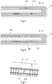
- Figs. 1 to 7 show an embodiment of the invention.
- the antenna has a core 1, a coil 2, a housing, a core carrier 4 and a potting compound 5.
- the core 1 is a magnetic core.
- the core 1 preferably extends along a longitudinal axis.
- the core 1 is preferably longer in the direction of the longitudinal axis than in the other directions / axes (at right angles to the longitudinal axis).
- the core 1 is made of a magnetic material.
- the core made of a ferrite material (ferrite material) or a powder material (powder core) is, for example, a ferrite material.
- Magnetic material means that the material is at least paramagnetic, preferably ferromagnetic.
- the magnetic core 1 is made of a hard material, i. the magnetic core 1 is not elastic or pliable.
- the magnetic core 1 preferably has a rectangular cross section.
- the magnetic core preferably consists of a plurality of sub-cores 1.1 and 1.2.
- the above-described material properties of the core 1 apply accordingly to each lower core 1.1, 1.2.
- the same magnetic materials are preferably used for different sub-cores 1.1 and 1.2.
- the plurality of sub-cores 1.1 and 1.2 has at least two sub-cores 1.1 and 1.2 with a first sub-core 1.1 and a second sub-core 1.2.
- the first sub-core has a first longitudinal axis.
- the second lower core has a second longitudinal axis.
- the first lower core 1.1 and the second lower core 1.2 are preferably arranged such that the second longitudinal axis extends as an extension of the first longitudinal axis (so that the first and second longitudinal axes form the longitudinal axis of the core 1). This means that the first and second longitudinal axes are not bent to one another, are arranged at 0 ° or 180 ° and / or are parallel / coaxial / overlapping with one another.
- the first lower core 1.1 has a first end and a second end (in the direction of the first longitudinal axis) opposite the first end.
- the second lower core 1.2 has a first end and a second end (in the direction of the second longitudinal axis) opposite the first end.
- the first end of the first sub-core 1.1 is preferably arranged opposite the first end of the second sub-core 1.2.
- the second end of the first lower core 1.1 thus forms a first end of the core 1 and, if the core 1 consists of the two lower cores 1.1, 1.2, the second end of the second lower core 1.2 forms a second end of the core 1.
- the first lower core 1.1 has a first cross section at right angles to the first longitudinal axis.
- the second lower core 1.2 has a second cross section at right angles to the second longitudinal axis.
- the second cross section preferably corresponds to the first cross section.
- the first lower core 1.1 and the second lower core 1.2 are preferably arranged in such a way that the first cross section of the first lower core 1.1 is arranged flush with the second cross section of the second lower core 1.2.
- the first lower core 1.1 preferably has the same first cross section along the entire first longitudinal axis.
- the second lower core 1.2 preferably has the same second cross section along the entire second longitudinal axis.
- the first sub-core 1.1 and the second sub-core 1.2 are preferably identical, so that the same parts can be used for both sub-cores 1.1, 1.2.
- the first lower core 1.1 is preferably arranged at a distance from the second lower core 1.2. This creates a gap between the first lower core 1.1 and the second lower core 1.2.
- the distance between the first lower core 1.1 and the second lower core 1.2 is preferably greater than 0.1 mm, preferably greater than 0.3 mm, preferably greater than 0.5 mm, preferably greater than 1 mm.
- the gap is preferably smaller than 10 mm, preferably smaller than 7 mm, preferably than 5 mm, since too large a gap could negatively influence the magnetic field lines between the two lower cores 1.1, 1.2.
- the coil 2 is wound around the core 1.
- the coil 2 preferably has a plurality of turns around the core 1, preferably with more than two, preferably with more than five, preferably with more than ten, preferably with more than fifteen, preferably with more than twenty turns.
- the coil 2 preferably extends from the first end of the core 1 or the second end of the first lower core 1.1 to the second end of the core 1 or the second end of the second lower core 1.2, so that the area between the last turn of the coil 2 in the direction of the first end of the core 1 or the second end of the first lower core 1.1 and the last turn of the coil 2 in the direction of the second end of the core 1 or the second end of the second lower core 1.2 at least 70%, preferably at least 75%, preferably make up at least 80% of the longitudinal extension of the core 1 or the two lower cores 1.1, 1.2 together.
- the coil 2 preferably extends over both lower cores 1.1, 1.2.
- the coil 2 preferably extends over both lower cores 1.1, 1.2.
- the coil 2 or a coil wire of the coil 2 is preferably wound onto the core carrier 4. However, it is also possible for the coil 2 or the coil wire (without a core carrier 4) to be wound directly onto the core 1.
- the coil 2 preferably has a coil wire which is wound around the core 1 or the core carrier 4.
- the coil wire is preferably insulated.
- the coil wire can also not be insulated. However, care would then have to be taken during the winding that the wire does not touch each other when it crosses and that it does not touch the core 1 either.
- the coil wire is wound so that both ends of the coil wire at one end of the core 1 are connected to terminals of the antenna.
- the coil 2 is wound from the first end of the core 1 to the second end of the core 1 in one direction and the coil wire is then wound from the second end of the core 1 to the first end of the core 1 (without turns around the core 1) returned.
- the core carrier 4 is designed to carry / hold the core 1. This is especially important for the assembly of the antenna before potting, so that all antenna parts are held in the correct position before the antenna is potted. The features of the core carrier 4 described below therefore relate to the state before the antenna was potted, unless explicitly stated otherwise.
- the core carrier 4 is preferably designed to carry the coil 2.
- the core carrier 4 preferably has an inner opening in which the core 1 is held.
- the core carrier 4 preferably has an outer surface on which the coil 2 is wound.
- the core carrier 4 is particularly advantageous for the exemplary embodiments with a plurality of lower cores 1.1, 1.2.
- the core carrier 4 preferably fixes (at least in one direction) the position of the lower cores 1.1, 1.2 with respect to one another.
- the core carrier 4 preferably fixes the lower cores 1.1, 1.2 in such a way that they are perpendicular to the longitudinal axis of the core 1 or the lower cores 1.1, 1.2 (at least in one direction, preferably in all directions 330 °, preferably 350 ° radially around the longitudinal axis, preferably in all directions radially around the longitudinal axis). At least one of the two lower cores 1.1, 1.2 (or both) can preferably be moved in the direction of the longitudinal axis when the two lower cores 1.1, 1.2 are mounted in the core carrier 4 and the coil 2 is wound around the core 1 on the core carrier 4.
- the installed antenna can thus be fine-tuned prior to casting by setting the distance between the two lower cores 1.1, 1.2 so that the desired antenna properties are met.
- the two lower cores 1.1, 1.2 are completely fixed in their position, so that the lower cores 1.1, 1.2 cannot move their position (absolutely and / or relative to one another).
- the lower cores 1.1, 1.2 are preferably introduced in the direction of the longitudinal axis of the core 1 or the lower cores 1.1, 1.2 for assembly. This allows the lower cores 1.1, 1.2 to be stably positioned with respect to one another and still move axially to one another can be.
- the core carrier 4 preferably extends from the second end of the first sub-core to the second end of the second sub-core. This allows the lower cores 1.1, 1.2 to be held in a stable manner. This is advantageous for positioning during production and also stabilizes the cast lower cores 1.1, 1.2 later in use.
- the core carrier 4 has at least one, preferably two parallel longitudinal carriers 41 (which extend in the direction of the longitudinal axis of the core 1).
- the core carrier 4 preferably has a plurality of transverse carriers 42 which prevent / block the movement of the lower cores 1.1, 1.2 radially to the longitudinal axis of the core 1.
- the winding of the coil 2 is preferably interrupted in the area of the cross member 42.
- the cross members 42 each preferably connect the two longitudinal members 41.
- four sides (at right angles to the longitudinal axis of the core 1) of the core 1 are used as an upper side (or first side), lower side (or second side) and two lateral sides (third and fourth page), but without restricting the invention to a specific orientation of the antenna.
- the upper and lower sides are opposite and / or the two lateral sides are opposite.
- the two longitudinal supports are preferably arranged on the two lateral sides of the core 1, so that the two lateral sides of the core 1 rest against the two longitudinal supports.
- the core carrier 4 preferably has at one end a closure region 43 which is designed to close an opening in the housing 3 when the core carrier 4 (with the core 1 and the coil 2) is mounted in the housing 3.
- the closure area 43 can be produced integrally with the rest of the core carrier 4 from one piece. It is also possible, however, for the closure area 43 and the rest of the core support 4 to be assembled from separate parts.
- the closure area 43 preferably has a connection for the electrical connection of the antenna, in particular the coil 2.
- the connection preferably has two electrically conductive rods which extend through the closure area 43. One side of each conductive stick protrudes from the closure area 43 on the outer side so that the finished antenna can be electrically connected.
- each conductive rod protrudes from the inner side of the closure area 43, the ends of the coil 2 or the coil wire being connected to one of these conductive rods (on the inside).
- the core carrier 4 is preferably designed such that the core carrier 4 has a predefined position after assembly in the housing 3. On one side of the antenna, this is achieved, for example, by positioning the closure area 43 in the opening of the housing 3.
- the core carrier 4 preferably further has positioning means 44 which hold the core carrier 4 in the predefined position when the core carrier 4 is mounted in the housing 3.
- the positioning means 44 are preferably arranged on the region of the core carrier 4 opposite to the closure region 43.
- the positioning means 44 are preferably resilient so that the positioning means 44 define the predefined position, but allow deviations from the predefined position in the event of vibrations or impacts.
- the positioning means 44 preferably have flexible / resilient arms 44 which press against the inner wall of the housing 3 and thus bring the core carrier 4 in the housing 3 into the predefined position. This is in the cuts DD and EE in the Fig. 5 and 6th shown.
- the core carrier 4 is preferably made of a plastic.
- the housing 3 is designed to enclose the core 1 with the coil 2.
- the housing 3 is preferably designed to enclose the core carrier 4 with the core 1 and the coil 2.
- the housing 3 preferably has an opening which is designed to introduce the core 1 with the coil 2 or the core carrier 4 with the core 1 and coil 2 into the housing 3.
- the opening is preferably closed by the core carrier 4 in the inserted state. However, it is also possible for the opening to be closed by a separate cover.
- a potting compound 5 is arranged between the housing 3 and the core 1 with the coil 2 or the core carrier 4 with the core 1 and the coil 2.
- the core 1 with the coil 2 or the core carrier 4 with the The core 1 and the coil 2 are inserted into the housing 3 and encapsulated therein with the potting compound 5.
- the sealing compound 5 is often referred to as potting.
- the potting compound 5 preferably fills the, preferably all, cavities in the housing 3 so that the heat from the core 1 and the coil 2 are effectively dissipated and the core 1 with the coil 2 or the core carrier 4 with the core 1 and the Coil 2 is stored stably.
- a casting compound 5 which (in the cured state) is softer than 40 Shore A, preferably 35 Shore A, preferably 30 Shore A, preferably 27 Shore A, preferably 25 Shore A. It was found that the Potting compound 5 is softer than 40 Shore A or than the preferred values mentioned, not only improves the breaking stability, but surprisingly also improves the stability of the electrical values of the antenna.
- the potting compound 5 (in the cured state) is, however, preferably harder than 10 Shore A, preferably than 15 Shore A. The potting compound 5 with a deformation between 10 and 40 Shore A has been found to be particularly advantageous.
- the core 1 possibly with the lower cores 1.1, 1.2, is first mounted in the core carrier 4.
- the coil 2 is wound on the core carrier 4 or the core 1.
- the coil wire is connected to the connector of the antenna.
- the core 1 with the coil 2 or the core carrier 4 with the core 1 and the coil 2 is inserted into the housing 3.
- the core 1 with the coil 2 or the core carrier 4 with the core 1 and the coil 2 is potted in the housing 3 with the potting compound 5.
- the potting compound 5 then hardens and the antenna is ready.
Landscapes
- Engineering & Computer Science (AREA)
- Power Engineering (AREA)
- Remote Sensing (AREA)
- Chemical & Material Sciences (AREA)
- Composite Materials (AREA)
- Mechanical Engineering (AREA)
- Computer Security & Cryptography (AREA)
- Radar, Positioning & Navigation (AREA)
- Manufacturing & Machinery (AREA)
- Support Of Aerials (AREA)
- Coils Or Transformers For Communication (AREA)
- Details Of Aerials (AREA)
Abstract
Description
- Die Erfindung bezieht sich auf eine Antenne, insbesondere auf eine Antenne für die Verwendung einem Fahrzeug ausgebildet für die Übertragung von Schlüsseldaten zum Öffnen und/oder Starten des Fahrzeugs.
- Antennen bestehen in der Regel aus einem ferromagnetischen Kern und einer Spule. Die Antennen werden in der Regel in einem Gehäuse vergossen. Je nach der Sendefrequenz und der Bandbreite muss der Kern und die Spule entsprechend ausgeführt werden. Die Bandbreiten von Antennen werden immer breiter, z.B. für UWB Antennen und die Reichweite der Antenne immer grösser, was zum Beispiel zur Folge hat, dass auch die Kerne immer länger werden. Lange Kerne sind aber auch bruchanfälliger als kürze Kerne und aufwendiger in der Herstellung.
- Deshalb ist inzwischen bekannt, den Kern durch eine Mehrzahl von hintereinander angeordneten Unterkernen auszubilden, z.B. in
US10056687 EP1397845 ,US2018/159224 . Dies hat den Vorteil, dass die Herstellung der einzelnen Unterkerne einfacher ist und die Bruchanfälligkeit der Unterkerne sinkt. Es hat sich aber gezeigt, dass die magnetischen Eigenschaften des aus mehreren Unterkernen gebildeten Kerns sehr anfällig gegen Stösse oder Temperaturschwankungen sind und diese Antennen oft Probleme mit der Stabilität der Antenneneigenschaften haben. - Grundsätzlich wäre es möglich eine weichere Vergussmasse zu verwenden, die Stöße besser dämpft und somit die Bruchanfälligkeit dämpft. Allerdings gibt es strenge Qualitätsvorgaben für die Positionierung der Antennenteile, die nur eine sehr kleine Toleranz für die Positionierung der Antennenteile erlaubt, damit eine Stabilität der elektrischen Eigenschaften der Antenne nicht beeinträchtigt wird. Deshalb wird die Vergussmasse nicht zu weich gewählt.
- Ein alternativer Ansatz wird in
US10062484 - Es ist ein Ziel der Erfindung, eine Antenne zu finden, die robust ist, einfach in der Herstellung ist und gute und stabile Antenneneigenschaften aufweist.
- Erfindungsgemäss wird dieses Ziel bei einer Antenne und einem Herstellungsverfahren für eine solche nach den unabhängigen Ansprüchen erzielt.
- Die Verwendung einer Vergussmasse 5 weicher als 40 Shore A schafft aufgrund der sehr guten Dämpfung sehr robuste Antennen. Überaschenderweise sind aber auch die Antenneneigenschaften sehr stabil. Dies liegt vielleicht darin, dass bei härteren Vergussmassen 5, ein Stoss zu einer Beschädigung der Vergussmasse 5 oder der Positioniermittel geführt hat und somit zu einer dauerhaften falschen Positionierung der Antenne bzw. von Antennenteilen. Durch die Verwendung von sehr weichen Vergussmassen, führt der Stoss nur zu einer sehr kurzen Verschiebung der Antennenteile in der Vergussmasse und danach werden die Antennenteile wieder an den gleichen ursprünglichen Ort zurückgeführt. Erfindungsgemäss wird eine kurzzeitige Überschreitung der vorgegebenen Toleranzen akzeptiert, um die Langzeitstabilität der Antenne zu verbessern. Somit wird durch die sehr weiche Vergussmasse eine sehr robuste Antenne mit sehr guten elektrischen Eigenschaften geschaffen.
- Alternativ wird die Aufgabe weiterhin durch eine Antenne gelöst aufweisend einen Kern und eine Spule, die um den Kern gewickelt ist mit einem oder einer Kombination der folgenden Merkmale. Diese Antenne kann auch keine Vergussmasse oder eine härtere Vergussmasse aufweisen.
- Weitere vorteilhafte Ausführungsformen sind in den abhängigen Ansprüchen angegeben.
- In einem Ausführungsbeispiel ist die Vergussmasse weicher als 35 Shore A, vorzugsweise weicher als 30 Shore A, vorzugsweise weicher als 27 Shore A, vorzugsweise weicher als 25 Shore A ist. Diese Härten der Vergussmasse ergaben noch bessere Werte für die Bruchstabilität und die Stabilität der elektrischen Werte. In einem Ausführungsbeispiel ist die Vergussmasse härter als 10 Shore A, vorzugsweise als 15 Shore A. In diesem Bereich oberhalb von 10 bzw. 15 Shore A wird ein Optimum zwischen Bruchstabilität und elektrischer Stabilität erreicht.
- In einem Ausführungsbeispiel weist der Kern eine Mehrzahl von Unterkernen auf, wobei die Mehrzahl von Unterkernen einen ersten Unterkern und einen zweiten Unterkern aufweist. Mehrere Unterkerne vereinfachen die Produktion des Kerns und Verbessern dessen Bruchstabilität. Insbesondere für Ausführungsbeispiele mit Unterkernen ist die weiche Vergussmasse vorteilhaft. Es wurde herausgefunden, dass die weiche Vergussmasse dazu führt, dass die relative Position der zwei Unterkerne nach Stössen weniger beeinflusst wird und somit die elektrischen Parameter der Antenne weniger beeinflusst werden. In einem Ausführungsbeispiel ist der erste Unterkern mit einem Abstand vom zweiten Unterkern angeordnet. Dies hat sich insbesondere in Kombination mit der weichen Vergussmasse als besonders vorteilhaft erwiesen. Die weiche Vergussmasse erlaubt den Unterkernen eine bestimmte Bewegungsspielraum bei Empfangen eines Stosses. Wenn die Unterkerne nun sich berühren, so wird ein Stoss von dem ersten Unterkern auf den zweiten Unterkern übertragen und kann somit die Bruchwahrscheinlichkeit der Unterkerne trotz weicher Vergussmasse wieder erhöhen. Durch den Spalt zwischen den Unterkernen wird dies vermieden. Falls sich die Unterkerne berühren, hängen die magnetischen Eigenschaften des gesamten Kerns sehr stark von der Kraft ab, mit der die beiden Unterkerne aneinander gedrückt werden. Durch die weiche Vergussmasse könnte der Anpressdruck der beiden Unterkerne stark variieren und sogar zu einer Separation der Unterkerne führen. Diese Variation des Anpressdrucks könnte durch Vibrationen, Stösse oder auch eine Variation der Temperatur verursacht werden. Dies führt zu grossen elektrischen Instabilitäten der Antenne, die nicht gewünscht sind. Deshalb ist es bei der Verwendung der weichen Vergussmasse in Kombination mit einer Mehrzahl von Unterkernen besonders vorteilhaft, einen Spalt zwischen den Unterkernen zu verwenden. Dadurch wird die thermische und elektrische Stabilität der Antenne wesentlich verbessert. In einem Ausführungsbeispiel wird der durch den Abstand gebildete Spalt von der Vergussmasse gefüllt. Somit wirkt die Vergussmasse zwischen den Unterkernen ebenfalls als Dämpfer und leitet auch so gut die Wärme zwischen den Unterkernen ab in die restliche Vergussmasse.
- In einem Ausführungsbeispiel weist der erste Unterkern eine erste Längsachse und der zweite Unterkern eine zweite Längsachse auf. In einem Ausführungsbeispiel sind der erste Unterkern und der zweite Unterkern so angeordnet, dass die zweite Längsachse sich in Verlängerung der ersten Längsachse erstreckt. In einem Ausführungsbeispiel weist der erste Unterkern rechtwinkelig zu der ersten Längsachse einen ersten Querschnitt auf und der zweite Unterkern rechtwinkelig zu der zweiten Längsachse einen zweiten Querschnitt auf. In einem Ausführungsbeispiel entspricht der zweite Querschnitt dem ersten Querschnitt. In einem Ausführungsbeispiel sind der erste Unterkern und der zweite Unterkern so angeordnet, dass der erste Querschnitt bündig zu dem zweiten Querschnitt angeordnet ist. In einem Ausführungsbeispiel weist der erste Unterkern entlang der gesamten ersten Längsachse den gleichen ersten Querschnitt auf. In einem Ausführungsbeispiel weist der zweite Unterkern entlang der gesamten zweiten Längsachse den gleichen zweiten Querschnitt auf.
- In einem Ausführungsbeispiel weist der erste Unterkern ein erstes Ende und ein dem ersten Ende gegenüberliegendes zweite Ende auf. In einem Ausführungsbeispiel weist der zweite Unterkern ein erstes Ende und ein dem ersten Ende gegenüberliegendes zweite Ende auf. In einem Ausführungsbeispiel ist das erste Ende des ersten Unterkerns gegenüber dem ersten Ende des zweiten Unterkerns angeordnet.
- In einem Ausführungsbeispiel weist die Antenne einen Kernträger auf. Der Kernträger erlaubt es bestimmte für die elektrische Stabilität gewünschte Bewegungen des Kerns zu unterbinden und andere für die elektrische Stabilität und die Bruchstabilität gewünschte Bewegungen zu erlauben. In einem Ausführungsbeispiel trägt der Kernträger den ersten und zweiten Unterkern. Insbesondere für Ausführungsbeispiele mit zwei Unterkernen, insbesondere mit solchen mit einem Spalt ist ein Kernträger sehr vorteilhaft, da er bei der ansonsten komplizierten Positionierung hilft.
- In einem Ausführungsbeispiel erstreckt der Kernträger sich von dem zweiten Ende des ersten Unterkerns bis zu dem zweiten Ende des zweiten Unterkerns (abgesehen von einem evtl. herausstehenden Ende eines Unterkerns, z.B. bis zu 10%, vorzugsweise bis zu 5% der Länge des Kerns 1). Dies erlaubt eine stabile Halterung der Unterkerne über die Länge des Kerns 1.
- In einem Ausführungsbeispiel wird die Spule auf den Kernträger gewickelt. Dies hat den Vorteil, dass die Unterkerne während dem Wickeln der Spule stabil gehalten werden. In einem Ausführungsbeispiel ist die Spule so gewickelt, dass die Spule sich über mehr als 80 % der Länge zwischen den zweiten Enden der Unterkerne erstreckt.
- In einem Ausführungsbeispiel ist der Kernträger, bevor die Unterkerne, der Kernträger und die Spule in dem Gehäuse mit dem Vergussmasse vergossen werden, ausgebildet, den ersten Unterkern und/oder den zweiten Unterkern in Richtung der Längsachse des entsprechenden Unterkerns in den Kernträger zur Montage einzuschieben.
- In einem Ausführungsbeispiel ist der Kernträger mit den montierten Unterkernen und der Spule, bevor die Unterkerne, der Kernträger und die Spule in dem Gehäuse mit dem Vergussmasse vergossen werden, ausgebildet, den ersten Unterkern und/oder den zweiten Unterkern in Richtung der Längsachse des entsprechenden Unterkerns zu verschieben.
- In einem Ausführungsbeispiel ist der Kernträger mit den montierten Unterkernen und der Spule, bevor die Unterkerne, der Kernträger und die Spule in dem Gehäuse mit dem Vergussmasse vergossen werden, ausgebildet, den ersten Unterkern und/oder den zweiten Unterkern rechtwinkelig zu der Richtung der Längsachse des entsprechenden Unterkerns zu fixieren.
- In einem Ausführungsbeispiel ist die Position des Kernträgers, der Spule, des ersten Unterkerns und/oder des zweiten Unterkerns in dem Gehäuse durch die Vergussmasse fixiert.
- In einem Ausführungsbeispiel ist die Antenne für die Verwendung in einem Fahrzeug ausgebildet und/oder für die Übertragung von Schlüsseldaten zum Öffnen und/oder Starten des Fahrzeugs.
- In einem Ausführungsbeispiel weist ein Fahrzeug eine zuvor beschriebene Antenne auf.
- Die Erfindung wird anhand der beigefügten Figuren näher erläutert, wobei zeigen
- Fig. 1
- eine 3D Ansicht eines ersten Ausführungsbeispiels einer Antenne mit halb-aufgeschnittenen Gehäuse und Vergussmasse.
- Fig. 2
- eine 3D Ansicht des ersten Ausführungsbeispiels der Antenne ohne Gehäuse und Vergussmasse.
- Fig. 3
- eine 3D Ansicht des ersten Ausführungsbeispiels der Antenne ohne Kernträger, Gehäuse und Vergussmasse.
- Fig. 3
- eine erste Schnittansicht durch die Antenne nach dem ersten Ausführungsbeispiel
- Fig. 4
- eine Draufsicht auf die Antenne nach dem ersten Ausführungsbeispiel.
- Fig. 5
- eine zweite Schnittansicht durch die Antenne nach dem ersten Ausführungsbeispiel entlang der Linie D-D.
- Fig. 6
- eine dritte Schnittansicht durch die Antenne nach dem ersten Ausführungsbeispiel entlang der Linie E-E.
- Fig. 7
- eine Vergrösserung des Ausschnitts F aus
Fig. 1 . -
Fig. 1 bis 7 zeigen ein Ausführungsbeispiel der Erfindung. - Die Antenne weist einen Kern 1, eine Spule 2, ein Gehäuse, einen Kernträger 4 und eine Vergussmasse 5 auf.
- Der Kern 1 ist ein magnetischer Kern. Der Kern 1 erstreckt sich vorzugsweise entlang einer Längsachse. Vorzugsweise ist der Kern 1 länger in Richtung der Längsachse als in die anderen (zu der Längsachse rechtwinkeligen) Richtungen/Achsen. Der Kern 1 ist aus einem magnetischen Material. Vorzugsweise ist der Kern aus einem Ferritmaterial (Ferritmaterial) oder einem Pulvermaterial (Pulverkern) zum Beispiel ein Ferritmaterial. Magnetisches Material bedeutet, dass das Material zumindest paramagnetisch ist, vorzugsweise ferromagnetisch ist. Der magnetisch Kern 1 ist aus einem harten Material, d.h. der magnetische Kern 1 ist nicht elastisch oder biegsam. Der magnetische Kern 1 hat vorzugsweise einen rechteckigen Querschnitt.
- Vorzugsweise besteht der magnetische Kern aus einer Mehrzahl von Unterkernen 1.1 und 1.2. Die oben beschriebenen Materialeigenschaften des Kerns 1 gilt entsprechend für jeden Unterkern 1.1, 1.2. Vorzugsweise werden die gleichen magnetischen Materialen für verschiedene Unterkerne 1.1 und 1.2 verwendet. Die Mehrzahl von Unterkernen 1.1 und 1.2 weist zumindest zwei Unterkerne 1.1 und 1.2 mit einem ersten Unterkern 1.1 und einem zweiten Unterkern 1.2 auf. Der erste Unterkern weist eine erste Längsachse auf. Der zweite Unterkern weit eine zweite Längsachse auf. Der erste Unterkern 1.1 und der zweite Unterkern 1.2 sind vorzugsweise so angeordnet sind, dass die zweite Längsachse sich in Verlängerung der ersten Längsachse erstreckt (so dass die erste und die zweite Längsachse die Längsachse des Kerns 1 ausbilden). Das heisst, die erste und zweite Längsachse sind zueinander nicht geknickt, sind mit 0° bzw. 180° angeordnet und/oder sind parallel/koaxial/überlappend zueinander. Der erste Unterkern 1.1 weist ein erstes Ende und ein (in Richtung der ersten Längsachse) gegenüber dem ersten Ende liegendes zweites Ende auf. Der zweite Unterkern 1.2 weist ein erstes Ende und ein (in Richtung der zweiten Längsachse) gegenüber dem ersten Ende liegendes zweites Ende auf. Das erste Ende des ersten Unterkerns 1.1 ist vorzugsweise gegenüber dem ersten Ende des zweiten Unterkerns 1.2 angeordnet. Somit bildet das zweite Ende des ersten Unterkern 1.1 ein erstes Ende des Kerns 1 aus und, falls der Kern 1 aus den zwei Unterkernen 1.1, 1.2 besteht, bildet das zweite Ende des zweiten Unterkerns 1.2 ein zweites Ende des Kerns 1 aus. Der erste Unterkern 1.1 weist rechtwinkelig zu der ersten Längsachse einen ersten Querschnitt auf. Der zweite Unterkern 1.2 weist rechtwinkelig zu der zweiten Längsachse einen zweiten Querschnitt auf. Vorzugsweise entspricht der zweite Querschnitt dem ersten Querschnitt. Vorzugsweise sind der erste Unterkern 1.1 und der zweite Unterkern 1.2 so angeordnet, dass der erste Querschnitt des ersten Unterkerns 1.1 bündig zu dem zweiten Querschnitt des zweiten Unterkerns 1.2 angeordnet ist. Dies soll heissen, dass der zweite Unterkern 1.2 die Verlängerung des ersten Unterkerns 1.1 in der ersten bzw. zweiten Längsachse ausbildet, wobei beide Unterkerne 1.1 koaxial angeordnete Längsachsen und gleiche Querschnitte haben (, die bei nicht rotationssymmetrischen Querschnitten so angeordnet sind, dass die Querschnitte vollständig überlappen). Vorzugsweise weist der erste Unterkern 1.1 entlang der gesamten ersten Längsachse den gleichen ersten Querschnitt auf. Vorzugsweise weist der zweite Unterkern 1.2 entlang der gesamten zweiten Längsachse den gleichen zweiten Querschnitt auf. Vorzugsweise sind der erste Unterkern 1.1 und der zweite Unterkern 1.2 identisch, so dass die gleichen Teile für beide Unterkerne 1.1, 1.2 verwendet werden können. Vorzugsweise ist der erste Unterkern 1.1 mit einem Abstand vom zweiten Unterkern 1.2 angeordnet ist. Dadurch entsteht ein Spalt zwischen dem ersten Unterkern 1.1 und dem zweiten Unterkern 1.2. Der Abstand zwischen dem ersten Unterkern 1.1 und dem zweiten Unterkern 1.2 ist vorzugsweise grösser als 0,1 mm, vorzugsweise grösser als 0,3 mm, vorzugsweise grösser als 0,5 mm, vorzugsweise grösser als 1 mm. Vorzugsweise ist der Spalt kleiner als 10 mm, vorzugsweise kleiner als 7 mm, vorzugsweise als 5 mm, da ein zu grosser Spalt die Magnetfeldlinien zwischen den beiden Unterkernen 1.1, 1.2 negativ beeinflussen könnte.
- Die Spule 2 ist um den Kern 1 gewickelt. Die Spule 2 weist vorzugsweise eine Mehrzahl von Windungen um den Kern 1 auf, vorzugsweise mit mehr als zwei, vorzugsweise mit mehr als fünf, vorzugsweise mit mehr als zehn, vorzugsweise mit mehr als fünfzehn, vorzugsweise mit mehr als zwanzig Windungen. Die Spule 2 erstreckt sich vorzugsweise von dem ersten Ende des Kerns 1 bzw. dem zweiten Ende des ersten Unterkerns 1.1 bis zu dem zweiten Ende des Kerns 1 bzw. dem zweiten Ende des zweiten Unterkerns 1.2, so dass der Bereich zwischen der letzten Windung der Spule 2 in Richtung des ersten Endes des Kerns 1 bzw. des zweiten Endes des ersten Unterkerns 1.1 und der letzten Windung der Spule 2 in Richtung zweiten Endes des Kerns 1 bzw. des zweiten Endes des zweiten Unterkerns 1.2 mindestens 70%, vorzugsweise mindestens 75%, vorzugsweise mindestens 80% der Längserstreckung des Kerns 1, bzw. der beiden Unterkerne 1.1, 1.2 zusammen ausmachen. Vorzugsweise erstreckt sich die Spule 2 über beide Unterkerne 1.1, 1.2. Die Spule 2 erstreckt sich vorzugsweise über beide Unterkerne 1.1, 1.2. Vorzugsweise ist die Spule 2 bzw. ein Spulendraht der Spule 2 auf den Kernträger 4 gewickelt. Allerdings ist es auch möglich, dass die Spule 2 bzw. der Spulendraht (ohne einen Kernträger 4) direkt auf den Kern 1 zu wickeln. Die Spule 2 weist vorzugsweise einen Spulendraht auf, der um den Kern 1, bzw. den Kernträger 4 gewickelt ist. Der Spulendraht ist vorzugsweise isoliert. Der Spulendraht kann aber auch nicht isoliert sein. Allerdings müsste dann bei der Wicklung aufgepasst werden, dass der Draht sich bei kreuzen nicht berührt und auch nicht den Kern 1 berührt. Vorzugsweise wird der Spulendraht so gewickelt, dass beide Enden des Spulendrahts an einem Ende des Kerns 1 mit Anschlüssen der Antenne verbunden sind. In dem gezeigten Ausführungsbeispiel ist die Spule 2 von dem ersten Ende des Kerns 1 zu dem zweiten Ende des Kerns 1 in eine Richtung gewickelt und der Spulendraht dann von dem zweiten Ende des Kerns 1 zu dem ersten Ende des Kerns 1 (ohne Windungen um den Kern 1) zurückgeführt. Es wäre aber auch möglich, den Spulendraht zuerst von dem ersten Ende des Kerns 1 zu dem zweiten Ende des Kerns 1 (ohne Windungen um den Kern 1) zu führen und dann von dem zweiten Ende des Kerns 1 zu dem ersten Ende des Kerns 1 in eine Richtung zu wickeln. Es ist auch möglich, den Spulendraht in beide Richtungen zu wickeln (Kreuzwicklung).
- Der Kernträger 4 ist ausgebildet den Kern 1 zu tragen/halten. Dies ist vor allem für die Montage der Antenne vor dem Vergiessen wichtig, so dass alle Antennenteile in der richtigen Position gehalten werden, bevor die Antenne vergossen wird. Die nachfolgend beschriebenen Merkmale des Kernträgers 4 beziehen sich deshalb auf den Zustand vor dem Vergiessen der Antenne, falls dies nicht explizit anders beschrieben ist. Der Kernträger 4 ist vorzugsweise ausgebildet, die Spule 2 zu tragen. Vorzugsweise weist der Kernträger 4 eine Innenöffnung auf, in der der Kern 1 gehalten wird. Vorzugsweise weist der Kernträger 4 eine Aussenfläche auf, auf der die Spule 2 gewickelt wird. Der Kernträger 4 ist insbesondere für die Ausführungsbeispiele mit einer Mehrzahl an Unterkernen 1.1, 1.2 vorteilhaft. Der Kernträger 4 fixiert (zumindest in eine Richtung) vorzugsweise die Position der Unterkerne 1.1, 1.2 zueinander. Vorzugsweise fixiert der Kernträger 4 die Unterkerne 1.1, 1.2 so, dass diese rechtwinkelig zu der Längsachse des Kerns 1 bzw. der Unterkerne 1.1, 1.2 (zumindest in eine Richtung, vorzugsweise in alle Richtungen 330°, vorzugsweise 350° radial um die Längsachse, vorzugsweise in alle Richtungen radial um die Längsachse). Vorzugsweise kann zumindest einer der beiden Unterkerne 1.1, 1.2 (oder auch beide) in Richtung der Längsachse bewegt werden, wenn die beiden Unterkerne 1.1, 1.2 in dem Kernträger 4 montiert sind und die Spule 2 auf dem Kernträger 4 um den Kern 1 gewickelt ist. So kann die montierte Antenne vor dem Vergiessen noch feinjustiert werden, in dem der Abstand zwischen den beiden Unterkernen 1.1, 1.2 so eingestellt wird, dass die gewünschten Antenneneigenschaften erfüllt sind. Allerdings ist es auch möglich, dass die beiden Unterkerne 1.1, 1.2 in Ihrer Position komplett fixiert sind, so dass die Unterkerne 1.1, 1.2 Ihre Position (absolut und/oder relativ zueinander) nicht bewegen können. Vorzugsweise werden die Unterkerne 1.1, 1.2 zur Montage in Richtung der Längsachse des Kerns 1 bzw. der Unterkerne 1.1, 1.2 eingeführt. Dies erlaubt, dass die Unterkerne 1.1, 1.2 zueinander stabil positioniert werden können und trotzdem axial zueinander bewegt werden können. Allerdings ist es auch möglich, die Unterkerne 1.1, 1.2 anders in den Kernträger 4 einzuführen. Vorzugsweise erstreckt sich der Kernträger 4 von dem zweiten Ende des ersten Unterkerns bis zu dem zweiten Ende des zweiten Unterkerns. Dies erlaubt eine stabile Halterung der Unterkerne 1.1, 1.2. Dies ist für die Positionierung während der Herstellung vorteilhaft, und stabilisiert die vergossenen Unterkerne 1.1, 1.2 auch später in der Anwendung. In dem gezeigten Ausführungsbeispiel weist der Kernträger 4 mindestens einen, vorzugsweise zwei parallele Längsträger 41 (der/die sich in Richtung der Längsachse des Kerns 1 erstreckt/erstrecken) auf. Vorzugsweise weist der Kernträger 4 eine Mehrzahl von Querträgern 42, die die Bewegung der Unterkerne 1.1, 1.2 radial zu der Längsachse des Kerns 1 unterbinden/blockieren. In dem Bereich der Querträger 42 ist die Wicklung der Spule 2 vorzugsweise unterbrochen. Vorzugsweise verbinden die Querträger 42 jeweils die zwei Längsträger 41. Zur Beschreibung werden vier Seiten (rechtwinkelig zu der Längsachse des Kerns 1) des Kerns 1 als obere Seite (oder erste Seite), untere Seite (oder zweite Seite) und zwei laterale Seiten (dritte und vierte Seite) bezeichnet, ohne damit aber die Erfindung auf eine bestimmte Ausrichtung der Antenne zu beschränken. Vorzugsweise sind die obere und untere Seite gegenüberliegend und/oder sind die beiden seitlichen Seiten gegenüberliegend. Es gibt vorzugsweise obere Querträger 42, an denen die obere Seite des Kerns 1 anliegt. Es gibt vorzugsweise untere Querträger 42, an denen die untere Seite des Kerns 1 anliegt. Vorzugsweise sind die beiden Längsträger an den zwei seitlichen Seiten des Kerns 1 angeordnet, so dass die beiden seitlichen Seiten des Kerns 1 an den beiden Längsträgern anliegen. Der Kernträger 4 weist vorzugsweise an einem Ende einen Verschlussbereich 43, der ausgebildet ist, eine Öffnung des Gehäuses 3 zu verschliessen, wenn der Kernträger 4 (mit dem Kern 1 und der Spule 2) in das Gehäuse 3 montiert ist. Der Verschlussbereich 43 kann dabei integral mit dem restlichen Kernträger 4 aus einem Stück hergestellt sein. Es ist aber auch möglich, dass der Verschlussbereich 43 und der restliche Kernträger 4 aus separaten Teilen zusammengesetzt wird. Der Verschlussbereich 43 weist vorzugsweise einen Anschluss für die elektrische Verbindung der Antenne, insbesondere der Spule 2 auf. Vorzugsweise weist der Anschluss zwei elektrisch leitende Stäbchen auf, die sich durch den Verschlussbereich 43 erstrecken. Eine Seite jedes leitenden Stäbchens steht dabei aus dem Verschlussbereich 43 auf der äusseren Seite heraus, so dass die fertige Antenne elektrisch verbunden werden kann. Die gegenüberliegende Seite jedes leitenden Stäbchens steht auf der inneren Seite des Verschlussbereichs 43 heraus, wobei die Enden der Spule 2 bzw. des Spulendrahts jeweils mit einem dieser leitenden Stäbchen (auf der Innenseite) verbunden werden. Der Kernträger 4 ist vorzugsweise so ausgebildet, dass der Kernträger 4 nach der Montage in dem Gehäuse 3 eine vordefinierte Position aufweist. Auf der einen Seite der Antenne ist dies zum Beispiel durch die Positionierung des Verschlussbereichs 43 in der Öffnung des Gehäuses 3 gelöst. Vorzugsweise weist der Kernträger 4 weiter Positionierungsmittel 44 auf, die den Kernträger 4 in der vordefinierten Position halten, wenn der Kernträger 4 in dem Gehäuse 3 montiert ist. Die Positionierungsmittel 44 sind vorzugsweise auf der zu dem Verschlussbereich 43 entgegengesetzten Bereich des Kernträgers 4 angeordnet. Vorzugsweise sind die Positionierungsmittel 44 federnd so dass die Positionierungsmittel 44 die vordefinierte Position definieren, aber bei Vibrationen oder Stössen, Abweichungen von der vordefinierten Position erlauben. Vorzugsweise weisen die Positionierungsmittel 44 biegsame/federnde Arme 44, die gegen die Innenwand des Gehäuses 3 drücken und so den Kernträger 4 in dem Gehäuse 3 in die vordefinierte Position bringen. Dies ist in den Schnitten D-D und E-E in den
Fig. 5 und6 gezeigt. Der Kernträger 4 ist vorzugsweise aus einem Kunststoff hergestellt. - Das Gehäuse 3 ist ausgebildet, den Kern 1 mit der Spule 2 zu umschliessen. Vorzugsweise ist das Gehäuse 3 ausgebildet, den Kernträger 4 mit dem Kern 1 und der Spule 2 zu umschliessen. Das Gehäuse 3 weist vorzugsweise eine Öffnung auf, die ausgebildet ist, den Kern 1 mit der Spule 2 bzw. den Kernträger 4 mit Kern 1 und Spule 2 in das Gehäuse 3 einzuführen. Vorzugsweise wird die Öffnung von dem Kernträger 4 in dem eingeführten Zustand verschlossen. Allerdings ist es auch möglich, dass die Öffnung von einem separaten Deckel geschlossen wird.
- Zwischen dem Gehäuse 3 und dem Kern 1 mit der Spule 2 bzw. dem Kernträger 4 mit dem Kern 1 und der Spule 2 ist eine Vergussmasse 5 angeordnet. Der Kern 1 mit der Spule 2 bzw. der Kernträger 4 mit dem Kern 1 und der Spule 2 wird in das Gehäuse 3 eingeführt und darin mit der Vergussmasse 5 vergossen. Die Vergussmasse 5 wird oft auch als Potting bezeichnet. Die Vergussmasse 5 füllt vorzugsweise die, vorzugsweise alle Hohlräume in dem Gehäuse 3 aus, so dass die Wärme von dem Kern 1 und der Spule 2 effektiv abgeleitet werden und der Kern 1 mit der Spule 2 bzw. der Kernträger 4 mit dem Kern 1 und der Spule 2 stabil gelagert wird. Erfindungsgemäss wird eine Vergussmasse 5 verwendet, die (im ausgehärteten Zustand) weicher ist als 40 Shore A, vorzugsweise als 35 Shore A, vorzugsweise als 30 Shore A, vorzugsweise als 27 Shore A, vorzugsweise als 25 Shore A. Es wurde herausgefunden, dass die Vergussmasse 5 weicher als 40 Shore A oder als die genannten bevorzugten Werte, nicht nur die Bruchstabilität verbessert, sondern überaschenderweise auch die Stabilität der elektrischen Werte der Antenne verbessert. Vorzugsweise ist die Vergussmasse 5 (im ausgehärteten Zustand) aber härter als 10 Shore A, vorzugsweise als 15 Shore A. Die Vergussmasse 5 mit einer Verformung zwischen 10 und 40 Shore A wurde als besonders vorteilhaft gefunden.
- Zur Herstellung der Antenne wird zuerst der Kern 1 evtl. mit den Unterkernen 1.1, 1.2 in den Kernträger 4 montiert. Die Spule 2 wird auf den Kernträger 4 oder den Kern 1 gewickelt. Der Spulendraht wird mit dem Anschluss der Antenne verbunden. Der Kern 1 mit der Spule 2 bzw. der Kernträger 4 mit dem Kern 1 und der Spule 2 wird in das Gehäuse 3 eingeführt. Der Kern 1 mit der Spule 2 bzw. der Kernträger 4 mit dem Kern 1 und der Spule 2 wird in dem Gehäuse 3 mit der Vergussmasse 5 vergossen. Danach härtet die Vergussmasse 5 aus und die Antenne ist fertig.
Claims (15)
- Antenne aufweisend ein Gehäuse (3), einen Kern (1) und eine Spule (2), die um den Kern (1) gewickelt ist, wobei der Kern (1) mit der Spule (2) in einer Vergussmasse (5) in dem Gehäuse (3) gelagert ist;
dadurch gekennzeichnet,
die Vergussmasse (5) weicher als 40 Shore A ist. - Antenne nach dem vorigen Anspruch, wobei die Vergussmasse (5) weicher als 30 Shore A ist.
- Antenne nach Anspruch 1 oder 2, wobei der Kern (1) eine Mehrzahl von Unterkernen (1.1, 1.2) aufweist, wobei die Mehrzahl von Unterkernen (1.1, 1.2) einen ersten Unterkern (1.1) und einen zweiten Unterkern (1.2) aufweist.
- Antenne nach Anspruch 3, wobei der erste Unterkern (1.1) eine erste Längsachse und der zweite Unterkern (1.2) eine zweite Längsachse aufweist, wobei der erste Unterkern (1.1) und der zweite Unterkern (1.2) so angeordnet sind, dass die zweite Längsachse sich in Verlängerung der ersten Längsachse erstreckt.
- Antenne nach Anspruch 4, wobei der erste Unterkern (1.1) rechtwinkelig zu der ersten Längsachse einen ersten Querschnitt aufweist, wobei der zweite Unterkern (1.2) rechtwinkelig zu der zweiten Längsachse einen zweiten Querschnitt, der dem ersten Querschnitt entspricht, aufweist, wobei
der erste Unterkern (1.1) und der zweite Unterkern (1.2) so angeordnet sind, dass der erste Querschnitt bündig zu dem zweiten Querschnitt angeordnet ist, und/oder
der erste Unterkern (1.1) entlang der gesamten ersten Längsachse den gleichen ersten Querschnitt aufweist, und/oder der zweite Unterkern (1.2) entlang der gesamten zweiten Längsachse den gleichen zweiten Querschnitt aufweist. - Antenne nach Anspruch 4 oder 5, wobei der erste Unterkern (1.1) mit einem Abstand vom zweiten Unterkern (1.2) angeordnet ist, und ein durch den Abstand gebildeter Spalt von der Vergussmasse (5) gefüllt ist.
- Antenne nach einem Ansprüche 3 bis 6 aufweisend einen Kernträger (4), wobei der erste Unterkern (1.1) und der zweite Unterkern (1.2) in dem Kernträger (4) gehalten sind.
- Antenne nach Anspruch 7, wobei der erste Unterkern (1.1) ein erstes Ende und ein dem ersten Ende gegenüberliegendes zweite Ende aufweist, wobei der zweite Unterkern (1.2) ein erstes Ende und ein dem ersten Ende gegenüberliegendes zweite Ende aufweist, wobei das erste Ende des ersten Unterkerns (1.1) gegenüber dem ersten Ende des zweiten Unterkerns (1.2) angeordnet ist, wobei der Kernträger (4) sich von dem zweiten Ende des ersten Unterkerns (1.1) bis zu dem zweiten Ende des zweiten Unterkerns (1.2) erstreckt.
- Antenne nach Anspruch 7 oder 8, wobei die Spule auf den Kernträger gewickelt wird, vorzugsweise so gewickelt, dass die Spule sich über mehr als 80 % der Länge zwischen den zweiten Enden der Unterkerne erstreckt.
- Antenne nach einem der Ansprüche 7 bis 9, wobei der Kernträger (4) mit den montierten Unterkernen (1.1, 1.2) und der Spule (2), bevor die Unterkerne (1.1, 1.2), der Kernträger (4) und die Spule (2) in dem Gehäuse (3) mit der Vergussmasse (5) vergossen werden, ausgebildet ist, den ersten Unterkern (1.1) und/oder den zweiten Unterkern (1.2) in Richtung der Längsachse des entsprechenden Unterkerns (1.1, 1.2) zu verschieben.
- Antenne nach einem der Ansprüche 7 bis 10, wobei der Kernträger mit den montierten Unterkernen und der Spule, bevor die Unterkerne, der Kernträger und die Spule in dem Gehäuse mit der Vergussmasse (5) vergossen werden, ausgebildet ist, den ersten Unterkern (1.1) und/oder den zweiten Unterkern (1.2) rechtwinkelig zu der Richtung der Längsachse des entsprechenden Unterkerns zu fixieren.
- Antenne nach einem der Ansprüche 7 bis 11, wobei die Position des Kernträgers (4), der Spule (2), des ersten Unterkerns (1.1) und/oder des zweiten Unterkerns (1.2) in dem Gehäuse (3) durch die Vergussmasse (5) fixiert ist.
- Antenne nach einem der vorigen Ansprüche für die Verwendung in einem Fahrzeug ausgebildet für die Übertragung von Schlüsseldaten zum Öffnen und/oder Starten des Fahrzeugs.
- Fahrzeug aufweisend eine Antenne nach Anspruch 14.
- Herstellungsverfahren für eine Antenne aufweisend die Schritte:Vergiessen eines mit einer Spule (2) umwickelten Kerns (1) mit einer Vergussmasse (5) in einem Gehäuse (3);Aushärten lassen der Vergussmasse (5);dadurch gekennzeichnet, dassdie ausgehärtete Vergussmasse (5) weicher als 40 Shore A ist.
Priority Applications (5)
| Application Number | Priority Date | Filing Date | Title |
|---|---|---|---|
| EP19169036.1A EP3723196B1 (de) | 2019-04-12 | 2019-04-12 | Antenne |
| JP2020055976A JP7710292B2 (ja) | 2019-04-12 | 2020-03-26 | アンテナ |
| CN202010279299.4A CN111816980B (zh) | 2019-04-12 | 2020-04-10 | 天线 |
| US16/845,845 US11563273B2 (en) | 2019-04-12 | 2020-04-10 | Antenna |
| KR1020200044170A KR20200120881A (ko) | 2019-04-12 | 2020-04-10 | 안테나 |
Applications Claiming Priority (1)
| Application Number | Priority Date | Filing Date | Title |
|---|---|---|---|
| EP19169036.1A EP3723196B1 (de) | 2019-04-12 | 2019-04-12 | Antenne |
Publications (2)
| Publication Number | Publication Date |
|---|---|
| EP3723196A1 true EP3723196A1 (de) | 2020-10-14 |
| EP3723196B1 EP3723196B1 (de) | 2023-07-12 |
Family
ID=66175291
Family Applications (1)
| Application Number | Title | Priority Date | Filing Date |
|---|---|---|---|
| EP19169036.1A Active EP3723196B1 (de) | 2019-04-12 | 2019-04-12 | Antenne |
Country Status (5)
| Country | Link |
|---|---|
| US (1) | US11563273B2 (de) |
| EP (1) | EP3723196B1 (de) |
| JP (1) | JP7710292B2 (de) |
| KR (1) | KR20200120881A (de) |
| CN (1) | CN111816980B (de) |
Families Citing this family (4)
| Publication number | Priority date | Publication date | Assignee | Title |
|---|---|---|---|---|
| DE102016125211B4 (de) * | 2016-12-21 | 2018-10-31 | Epcos Ag | Antennensegment und Mehrsegmentantenne |
| USD944781S1 (en) * | 2019-09-27 | 2022-03-01 | Make Great Sales Limited | Antenna |
| CN116195122A (zh) | 2020-09-18 | 2023-05-30 | 株式会社Lg新能源 | 用于电化学装置的隔板和制造其的方法 |
| EP4447222A1 (de) * | 2023-04-13 | 2024-10-16 | Schaffner EMV AG | Antenne und verfahren zur herstellung einer antenne |
Citations (8)
| Publication number | Priority date | Publication date | Assignee | Title |
|---|---|---|---|---|
| EP1397845A2 (de) | 2001-05-23 | 2004-03-17 | Neosid Pemetzrieder Gmbh & Co. Kg | Ferritantenne |
| DE102005057556A1 (de) * | 2005-11-30 | 2007-05-31 | Huf Hülsbeck & Fürst GmbH & Co KG | Ferritkern-Antennenanordnung für einen Kraftfahrzeug-Türaußengriff |
| FR2920916A1 (fr) * | 2007-09-12 | 2009-03-13 | Valeo Securite Habitacle Sas | Procede de fabrication d'un capteur d'approche etanche aux conditions environnementales exterieures, capteur d'approche etanche aux conditions environnementales exterieures et poignee associee |
| DE102016010493A1 (de) * | 2016-08-31 | 2018-03-01 | Huf Hülsbeck & Fürst Gmbh & Co. Kg | Kraftfahrzeugtürgriffanordnung mit abgedichtetem Elektronikbauraum |
| US20180122551A1 (en) * | 2015-04-15 | 2018-05-03 | Autonetworks Technologies, Ltd. | Reactor |
| US20180159224A1 (en) | 2016-12-02 | 2018-06-07 | Sumida Corporation | Antenna device and manufacturing method for the same |
| US10056687B2 (en) | 2016-03-04 | 2018-08-21 | Premo, S.L. | Flexible elongated inductor and elongated and flexible low-frequency antenna |
| US10062484B2 (en) | 2014-09-09 | 2018-08-28 | Premo, S.L. | Flexible soft magnetic core, antenna with flexible soft magnetic core and method for producing a flexible soft magnetic core |
Family Cites Families (7)
| Publication number | Priority date | Publication date | Assignee | Title |
|---|---|---|---|---|
| US6812707B2 (en) * | 2001-11-27 | 2004-11-02 | Mitsubishi Materials Corporation | Detection element for objects and detection device using the same |
| JP3975885B2 (ja) * | 2002-10-31 | 2007-09-12 | 株式会社デンソー | 携帯機 |
| JP2007043588A (ja) | 2005-08-05 | 2007-02-15 | Murata Mfg Co Ltd | コイルアンテナ |
| JP4655230B2 (ja) * | 2006-09-20 | 2011-03-23 | アイシン精機株式会社 | バーアンテナ用ボビン、バーアンテナ及び車両用ドアハンドル |
| JP4962810B2 (ja) | 2010-08-04 | 2012-06-27 | アイシン精機株式会社 | バーアンテナをもつ自動車用ドアハンドル |
| ES2655845T3 (es) | 2012-06-21 | 2018-02-21 | Murata Manufacturing Co., Ltd. | Antena de barra |
| CN103730723B (zh) * | 2014-01-07 | 2017-06-06 | 北京卫星环境工程研究所 | 一种星载等离子体天线产生及发射装置及其通信方法 |
-
2019
- 2019-04-12 EP EP19169036.1A patent/EP3723196B1/de active Active
-
2020
- 2020-03-26 JP JP2020055976A patent/JP7710292B2/ja active Active
- 2020-04-10 US US16/845,845 patent/US11563273B2/en active Active
- 2020-04-10 KR KR1020200044170A patent/KR20200120881A/ko not_active Ceased
- 2020-04-10 CN CN202010279299.4A patent/CN111816980B/zh active Active
Patent Citations (8)
| Publication number | Priority date | Publication date | Assignee | Title |
|---|---|---|---|---|
| EP1397845A2 (de) | 2001-05-23 | 2004-03-17 | Neosid Pemetzrieder Gmbh & Co. Kg | Ferritantenne |
| DE102005057556A1 (de) * | 2005-11-30 | 2007-05-31 | Huf Hülsbeck & Fürst GmbH & Co KG | Ferritkern-Antennenanordnung für einen Kraftfahrzeug-Türaußengriff |
| FR2920916A1 (fr) * | 2007-09-12 | 2009-03-13 | Valeo Securite Habitacle Sas | Procede de fabrication d'un capteur d'approche etanche aux conditions environnementales exterieures, capteur d'approche etanche aux conditions environnementales exterieures et poignee associee |
| US10062484B2 (en) | 2014-09-09 | 2018-08-28 | Premo, S.L. | Flexible soft magnetic core, antenna with flexible soft magnetic core and method for producing a flexible soft magnetic core |
| US20180122551A1 (en) * | 2015-04-15 | 2018-05-03 | Autonetworks Technologies, Ltd. | Reactor |
| US10056687B2 (en) | 2016-03-04 | 2018-08-21 | Premo, S.L. | Flexible elongated inductor and elongated and flexible low-frequency antenna |
| DE102016010493A1 (de) * | 2016-08-31 | 2018-03-01 | Huf Hülsbeck & Fürst Gmbh & Co. Kg | Kraftfahrzeugtürgriffanordnung mit abgedichtetem Elektronikbauraum |
| US20180159224A1 (en) | 2016-12-02 | 2018-06-07 | Sumida Corporation | Antenna device and manufacturing method for the same |
Also Published As
| Publication number | Publication date |
|---|---|
| JP2020174348A (ja) | 2020-10-22 |
| KR20200120881A (ko) | 2020-10-22 |
| CN111816980A (zh) | 2020-10-23 |
| JP7710292B2 (ja) | 2025-07-18 |
| US20200328513A1 (en) | 2020-10-15 |
| EP3723196B1 (de) | 2023-07-12 |
| US11563273B2 (en) | 2023-01-24 |
| CN111816980B (zh) | 2026-02-13 |
Similar Documents
| Publication | Publication Date | Title |
|---|---|---|
| EP3723196B1 (de) | Antenne | |
| EP3726651B1 (de) | Antenne | |
| DE3109268A1 (de) | Zeilentransformator | |
| EP1774545B1 (de) | Halterung für eine elektrische komponente | |
| DE69114628T2 (de) | Rücklauftransistor. | |
| DE1934795A1 (de) | Schutzrohrankerkontakt | |
| EP0660459B1 (de) | Vielfach-Flachstecker | |
| DE4310156C2 (de) | Gegen Umgebungseinflüsse geschützte Spulenvorrichtung, insbesondere Solenoid | |
| DE4041879A1 (de) | Spulenkoerper | |
| EP4046173B1 (de) | Formadaptive halterung für eine kernausführung und damit hergestelltes induktives bauelement | |
| EP2387045A1 (de) | Spulenkörper | |
| DE102011005165B4 (de) | Spule mit einer Wicklung, die eine Durchmesserreduzierung aufweist, Stromsensor mit einer solchen Spule und Verfahren zur Herstellung einer solchen Spule und eines solchen Stromsensors | |
| DE3100817A1 (de) | Polarisiertes elektromagnetisches relais | |
| DE1614754B2 (de) | Schutzrohrankerkontakt | |
| EP3731343A1 (de) | Antenne | |
| DE102016221866B4 (de) | Induktives Bauteil und Verfahren zur automatisierten Herstellung des induktiven Bauteils | |
| DE102016107818B4 (de) | Drosselanordnung mit einem Einsatz | |
| DE2652171A1 (de) | Vorschaltgeraet u.dgl. mit e- und i-foermigen kernblechen | |
| EP0142061B1 (de) | Elektromagnetische Relais und Verfahren zu dessen Herstellung | |
| DE3212335C2 (de) | Mit Schaltleitungen versehenes Schaltstück für Trockentransformatoren | |
| DE1109268B (de) | Klein- und Kleinstspule auf einem zylindrischen Spulenkoerper aus magnetisierbarem Blech | |
| DE2139510A1 (de) | Spulenkoerper fuer elektromagnete | |
| DE2816042C2 (de) | Verfahren zur Herstellung einer Anordnung für einen elektrischen Schwingkreis | |
| DE2450513A1 (de) | Drosselspule | |
| DE202017104818U1 (de) | Anwickelpfosten |
Legal Events
| Date | Code | Title | Description |
|---|---|---|---|
| PUAI | Public reference made under article 153(3) epc to a published international application that has entered the european phase |
Free format text: ORIGINAL CODE: 0009012 |
|
| STAA | Information on the status of an ep patent application or granted ep patent |
Free format text: STATUS: THE APPLICATION HAS BEEN PUBLISHED |
|
| AK | Designated contracting states |
Kind code of ref document: A1 Designated state(s): AL AT BE BG CH CY CZ DE DK EE ES FI FR GB GR HR HU IE IS IT LI LT LU LV MC MK MT NL NO PL PT RO RS SE SI SK SM TR |
|
| AX | Request for extension of the european patent |
Extension state: BA ME |
|
| STAA | Information on the status of an ep patent application or granted ep patent |
Free format text: STATUS: REQUEST FOR EXAMINATION WAS MADE |
|
| 17P | Request for examination filed |
Effective date: 20210329 |
|
| RBV | Designated contracting states (corrected) |
Designated state(s): AL AT BE BG CH CY CZ DE DK EE ES FI FR GB GR HR HU IE IS IT LI LT LU LV MC MK MT NL NO PL PT RO RS SE SI SK SM TR |
|
| RIC1 | Information provided on ipc code assigned before grant |
Ipc: H01F 17/04 20060101ALN20221221BHEP Ipc: H01F 41/00 20060101ALI20221221BHEP Ipc: H01F 27/26 20060101ALI20221221BHEP Ipc: H01F 27/02 20060101ALI20221221BHEP Ipc: H01F 3/14 20060101ALI20221221BHEP Ipc: H01Q 1/40 20060101ALI20221221BHEP Ipc: H01F 3/10 20060101ALI20221221BHEP Ipc: H01Q 7/08 20060101ALI20221221BHEP Ipc: H01Q 1/32 20060101AFI20221221BHEP |
|
| GRAP | Despatch of communication of intention to grant a patent |
Free format text: ORIGINAL CODE: EPIDOSNIGR1 |
|
| STAA | Information on the status of an ep patent application or granted ep patent |
Free format text: STATUS: GRANT OF PATENT IS INTENDED |
|
| INTG | Intention to grant announced |
Effective date: 20230202 |
|
| RIC1 | Information provided on ipc code assigned before grant |
Ipc: H01F 17/04 20060101ALN20230120BHEP Ipc: H01F 41/00 20060101ALI20230120BHEP Ipc: H01F 27/26 20060101ALI20230120BHEP Ipc: H01F 27/02 20060101ALI20230120BHEP Ipc: H01F 3/14 20060101ALI20230120BHEP Ipc: H01Q 1/40 20060101ALI20230120BHEP Ipc: H01F 3/10 20060101ALI20230120BHEP Ipc: H01Q 7/08 20060101ALI20230120BHEP Ipc: H01Q 1/32 20060101AFI20230120BHEP |
|
| GRAS | Grant fee paid |
Free format text: ORIGINAL CODE: EPIDOSNIGR3 |
|
| GRAA | (expected) grant |
Free format text: ORIGINAL CODE: 0009210 |
|
| STAA | Information on the status of an ep patent application or granted ep patent |
Free format text: STATUS: THE PATENT HAS BEEN GRANTED |
|
| AK | Designated contracting states |
Kind code of ref document: B1 Designated state(s): AL AT BE BG CH CY CZ DE DK EE ES FI FR GB GR HR HU IE IS IT LI LT LU LV MC MK MT NL NO PL PT RO RS SE SI SK SM TR |
|
| REG | Reference to a national code |
Ref country code: CH Ref legal event code: EP |
|
| REG | Reference to a national code |
Ref country code: IE Ref legal event code: FG4D Free format text: LANGUAGE OF EP DOCUMENT: GERMAN |
|
| REG | Reference to a national code |
Ref country code: DE Ref legal event code: R096 Ref document number: 502019008458 Country of ref document: DE |
|
| REG | Reference to a national code |
Ref country code: LT Ref legal event code: MG9D |
|
| REG | Reference to a national code |
Ref country code: NL Ref legal event code: MP Effective date: 20230712 |
|
| PG25 | Lapsed in a contracting state [announced via postgrant information from national office to epo] |
Ref country code: NL Free format text: LAPSE BECAUSE OF FAILURE TO SUBMIT A TRANSLATION OF THE DESCRIPTION OR TO PAY THE FEE WITHIN THE PRESCRIBED TIME-LIMIT Effective date: 20230712 |
|
| PG25 | Lapsed in a contracting state [announced via postgrant information from national office to epo] |
Ref country code: GR Free format text: LAPSE BECAUSE OF FAILURE TO SUBMIT A TRANSLATION OF THE DESCRIPTION OR TO PAY THE FEE WITHIN THE PRESCRIBED TIME-LIMIT Effective date: 20231013 |
|
| PG25 | Lapsed in a contracting state [announced via postgrant information from national office to epo] |
Ref country code: ES Free format text: LAPSE BECAUSE OF FAILURE TO SUBMIT A TRANSLATION OF THE DESCRIPTION OR TO PAY THE FEE WITHIN THE PRESCRIBED TIME-LIMIT Effective date: 20230712 |
|
| PG25 | Lapsed in a contracting state [announced via postgrant information from national office to epo] |
Ref country code: IS Free format text: LAPSE BECAUSE OF FAILURE TO SUBMIT A TRANSLATION OF THE DESCRIPTION OR TO PAY THE FEE WITHIN THE PRESCRIBED TIME-LIMIT Effective date: 20231112 |
|
| PG25 | Lapsed in a contracting state [announced via postgrant information from national office to epo] |
Ref country code: SE Free format text: LAPSE BECAUSE OF FAILURE TO SUBMIT A TRANSLATION OF THE DESCRIPTION OR TO PAY THE FEE WITHIN THE PRESCRIBED TIME-LIMIT Effective date: 20230712 Ref country code: RS Free format text: LAPSE BECAUSE OF FAILURE TO SUBMIT A TRANSLATION OF THE DESCRIPTION OR TO PAY THE FEE WITHIN THE PRESCRIBED TIME-LIMIT Effective date: 20230712 Ref country code: PT Free format text: LAPSE BECAUSE OF FAILURE TO SUBMIT A TRANSLATION OF THE DESCRIPTION OR TO PAY THE FEE WITHIN THE PRESCRIBED TIME-LIMIT Effective date: 20231113 Ref country code: NO Free format text: LAPSE BECAUSE OF FAILURE TO SUBMIT A TRANSLATION OF THE DESCRIPTION OR TO PAY THE FEE WITHIN THE PRESCRIBED TIME-LIMIT Effective date: 20231012 Ref country code: LV Free format text: LAPSE BECAUSE OF FAILURE TO SUBMIT A TRANSLATION OF THE DESCRIPTION OR TO PAY THE FEE WITHIN THE PRESCRIBED TIME-LIMIT Effective date: 20230712 Ref country code: LT Free format text: LAPSE BECAUSE OF FAILURE TO SUBMIT A TRANSLATION OF THE DESCRIPTION OR TO PAY THE FEE WITHIN THE PRESCRIBED TIME-LIMIT Effective date: 20230712 Ref country code: IS Free format text: LAPSE BECAUSE OF FAILURE TO SUBMIT A TRANSLATION OF THE DESCRIPTION OR TO PAY THE FEE WITHIN THE PRESCRIBED TIME-LIMIT Effective date: 20231112 Ref country code: HR Free format text: LAPSE BECAUSE OF FAILURE TO SUBMIT A TRANSLATION OF THE DESCRIPTION OR TO PAY THE FEE WITHIN THE PRESCRIBED TIME-LIMIT Effective date: 20230712 Ref country code: GR Free format text: LAPSE BECAUSE OF FAILURE TO SUBMIT A TRANSLATION OF THE DESCRIPTION OR TO PAY THE FEE WITHIN THE PRESCRIBED TIME-LIMIT Effective date: 20231013 Ref country code: FI Free format text: LAPSE BECAUSE OF FAILURE TO SUBMIT A TRANSLATION OF THE DESCRIPTION OR TO PAY THE FEE WITHIN THE PRESCRIBED TIME-LIMIT Effective date: 20230712 Ref country code: ES Free format text: LAPSE BECAUSE OF FAILURE TO SUBMIT A TRANSLATION OF THE DESCRIPTION OR TO PAY THE FEE WITHIN THE PRESCRIBED TIME-LIMIT Effective date: 20230712 |
|
| PG25 | Lapsed in a contracting state [announced via postgrant information from national office to epo] |
Ref country code: PL Free format text: LAPSE BECAUSE OF FAILURE TO SUBMIT A TRANSLATION OF THE DESCRIPTION OR TO PAY THE FEE WITHIN THE PRESCRIBED TIME-LIMIT Effective date: 20230712 |
|
| REG | Reference to a national code |
Ref country code: DE Ref legal event code: R097 Ref document number: 502019008458 Country of ref document: DE |
|
| PG25 | Lapsed in a contracting state [announced via postgrant information from national office to epo] |
Ref country code: SM Free format text: LAPSE BECAUSE OF FAILURE TO SUBMIT A TRANSLATION OF THE DESCRIPTION OR TO PAY THE FEE WITHIN THE PRESCRIBED TIME-LIMIT Effective date: 20230712 Ref country code: RO Free format text: LAPSE BECAUSE OF FAILURE TO SUBMIT A TRANSLATION OF THE DESCRIPTION OR TO PAY THE FEE WITHIN THE PRESCRIBED TIME-LIMIT Effective date: 20230712 Ref country code: EE Free format text: LAPSE BECAUSE OF FAILURE TO SUBMIT A TRANSLATION OF THE DESCRIPTION OR TO PAY THE FEE WITHIN THE PRESCRIBED TIME-LIMIT Effective date: 20230712 Ref country code: DK Free format text: LAPSE BECAUSE OF FAILURE TO SUBMIT A TRANSLATION OF THE DESCRIPTION OR TO PAY THE FEE WITHIN THE PRESCRIBED TIME-LIMIT Effective date: 20230712 Ref country code: CZ Free format text: LAPSE BECAUSE OF FAILURE TO SUBMIT A TRANSLATION OF THE DESCRIPTION OR TO PAY THE FEE WITHIN THE PRESCRIBED TIME-LIMIT Effective date: 20230712 Ref country code: SK Free format text: LAPSE BECAUSE OF FAILURE TO SUBMIT A TRANSLATION OF THE DESCRIPTION OR TO PAY THE FEE WITHIN THE PRESCRIBED TIME-LIMIT Effective date: 20230712 |
|
| PLBE | No opposition filed within time limit |
Free format text: ORIGINAL CODE: 0009261 |
|
| STAA | Information on the status of an ep patent application or granted ep patent |
Free format text: STATUS: NO OPPOSITION FILED WITHIN TIME LIMIT |
|
| PG25 | Lapsed in a contracting state [announced via postgrant information from national office to epo] |
Ref country code: IT Free format text: LAPSE BECAUSE OF FAILURE TO SUBMIT A TRANSLATION OF THE DESCRIPTION OR TO PAY THE FEE WITHIN THE PRESCRIBED TIME-LIMIT Effective date: 20230712 |
|
| 26N | No opposition filed |
Effective date: 20240415 |
|
| PG25 | Lapsed in a contracting state [announced via postgrant information from national office to epo] |
Ref country code: SI Free format text: LAPSE BECAUSE OF FAILURE TO SUBMIT A TRANSLATION OF THE DESCRIPTION OR TO PAY THE FEE WITHIN THE PRESCRIBED TIME-LIMIT Effective date: 20230712 |
|
| PG25 | Lapsed in a contracting state [announced via postgrant information from national office to epo] |
Ref country code: BG Free format text: LAPSE BECAUSE OF FAILURE TO SUBMIT A TRANSLATION OF THE DESCRIPTION OR TO PAY THE FEE WITHIN THE PRESCRIBED TIME-LIMIT Effective date: 20230712 |
|
| PG25 | Lapsed in a contracting state [announced via postgrant information from national office to epo] |
Ref country code: MC Free format text: LAPSE BECAUSE OF FAILURE TO SUBMIT A TRANSLATION OF THE DESCRIPTION OR TO PAY THE FEE WITHIN THE PRESCRIBED TIME-LIMIT Effective date: 20230712 |
|
| PG25 | Lapsed in a contracting state [announced via postgrant information from national office to epo] |
Ref country code: MC Free format text: LAPSE BECAUSE OF FAILURE TO SUBMIT A TRANSLATION OF THE DESCRIPTION OR TO PAY THE FEE WITHIN THE PRESCRIBED TIME-LIMIT Effective date: 20230712 Ref country code: BG Free format text: LAPSE BECAUSE OF FAILURE TO SUBMIT A TRANSLATION OF THE DESCRIPTION OR TO PAY THE FEE WITHIN THE PRESCRIBED TIME-LIMIT Effective date: 20230712 |
|
| REG | Reference to a national code |
Ref country code: CH Ref legal event code: PL |
|
| PG25 | Lapsed in a contracting state [announced via postgrant information from national office to epo] |
Ref country code: LU Free format text: LAPSE BECAUSE OF NON-PAYMENT OF DUE FEES Effective date: 20240412 |
|
| GBPC | Gb: european patent ceased through non-payment of renewal fee |
Effective date: 20240412 |
|
| REG | Reference to a national code |
Ref country code: BE Ref legal event code: MM Effective date: 20240430 |
|
| PG25 | Lapsed in a contracting state [announced via postgrant information from national office to epo] |
Ref country code: LU Free format text: LAPSE BECAUSE OF NON-PAYMENT OF DUE FEES Effective date: 20240412 |
|
| PG25 | Lapsed in a contracting state [announced via postgrant information from national office to epo] |
Ref country code: BE Free format text: LAPSE BECAUSE OF NON-PAYMENT OF DUE FEES Effective date: 20240430 |
|
| PG25 | Lapsed in a contracting state [announced via postgrant information from national office to epo] |
Ref country code: GB Free format text: LAPSE BECAUSE OF NON-PAYMENT OF DUE FEES Effective date: 20240412 |
|
| PG25 | Lapsed in a contracting state [announced via postgrant information from national office to epo] |
Ref country code: GB Free format text: LAPSE BECAUSE OF NON-PAYMENT OF DUE FEES Effective date: 20240412 Ref country code: BE Free format text: LAPSE BECAUSE OF NON-PAYMENT OF DUE FEES Effective date: 20240430 Ref country code: CH Free format text: LAPSE BECAUSE OF NON-PAYMENT OF DUE FEES Effective date: 20240430 |
|
| PG25 | Lapsed in a contracting state [announced via postgrant information from national office to epo] |
Ref country code: IE Free format text: LAPSE BECAUSE OF NON-PAYMENT OF DUE FEES Effective date: 20240412 |
|
| REG | Reference to a national code |
Ref country code: AT Ref legal event code: MM01 Ref document number: 1588106 Country of ref document: AT Kind code of ref document: T Effective date: 20240412 |
|
| PGFP | Annual fee paid to national office [announced via postgrant information from national office to epo] |
Ref country code: DE Payment date: 20250422 Year of fee payment: 7 |
|
| PG25 | Lapsed in a contracting state [announced via postgrant information from national office to epo] |
Ref country code: AT Free format text: LAPSE BECAUSE OF NON-PAYMENT OF DUE FEES Effective date: 20240412 |
|
| PG25 | Lapsed in a contracting state [announced via postgrant information from national office to epo] |
Ref country code: CY Free format text: LAPSE BECAUSE OF FAILURE TO SUBMIT A TRANSLATION OF THE DESCRIPTION OR TO PAY THE FEE WITHIN THE PRESCRIBED TIME-LIMIT; INVALID AB INITIO Effective date: 20190412 |
|
| PG25 | Lapsed in a contracting state [announced via postgrant information from national office to epo] |
Ref country code: HU Free format text: LAPSE BECAUSE OF FAILURE TO SUBMIT A TRANSLATION OF THE DESCRIPTION OR TO PAY THE FEE WITHIN THE PRESCRIBED TIME-LIMIT; INVALID AB INITIO Effective date: 20190412 |
|
| PGFP | Annual fee paid to national office [announced via postgrant information from national office to epo] |
Ref country code: FR Payment date: 20260309 Year of fee payment: 8 |
|
| REG | Reference to a national code |
Ref country code: DE Ref legal event code: R081 Ref document number: 502019008458 Country of ref document: DE Owner name: TE CONNECTIVITY SOLUTIONS GMBH, CH Free format text: FORMER OWNER: SCHAFFNER EMV AG, LUTERBACH, CH |