EP3723395B1 - Kommunikationsverfahren und zugehöriges produkt - Google Patents
Kommunikationsverfahren und zugehöriges produkt Download PDFInfo
- Publication number
- EP3723395B1 EP3723395B1 EP18897311.9A EP18897311A EP3723395B1 EP 3723395 B1 EP3723395 B1 EP 3723395B1 EP 18897311 A EP18897311 A EP 18897311A EP 3723395 B1 EP3723395 B1 EP 3723395B1
- Authority
- EP
- European Patent Office
- Prior art keywords
- multicast
- manner
- multicast service
- service data
- user equipment
- Prior art date
- Legal status (The legal status is an assumption and is not a legal conclusion. Google has not performed a legal analysis and makes no representation as to the accuracy of the status listed.)
- Active
Links
Images






Classifications
-
- H—ELECTRICITY
- H04—ELECTRIC COMMUNICATION TECHNIQUE
- H04L—TRANSMISSION OF DIGITAL INFORMATION, e.g. TELEGRAPHIC COMMUNICATION
- H04L12/00—Data switching networks
- H04L12/02—Details
- H04L12/16—Arrangements for providing special services to substations
- H04L12/18—Arrangements for providing special services to substations for broadcast or conference, e.g. multicast
- H04L12/185—Arrangements for providing special services to substations for broadcast or conference, e.g. multicast with management of multicast group membership
-
- H—ELECTRICITY
- H04—ELECTRIC COMMUNICATION TECHNIQUE
- H04L—TRANSMISSION OF DIGITAL INFORMATION, e.g. TELEGRAPHIC COMMUNICATION
- H04L12/00—Data switching networks
- H04L12/02—Details
- H04L12/16—Arrangements for providing special services to substations
- H04L12/18—Arrangements for providing special services to substations for broadcast or conference, e.g. multicast
- H04L12/189—Arrangements for providing special services to substations for broadcast or conference, e.g. multicast in combination with wireless systems
-
- H—ELECTRICITY
- H04—ELECTRIC COMMUNICATION TECHNIQUE
- H04W—WIRELESS COMMUNICATION NETWORKS
- H04W28/00—Network traffic management; Network resource management
- H04W28/02—Traffic management, e.g. flow control or congestion control
- H04W28/04—Error control
-
- H—ELECTRICITY
- H04—ELECTRIC COMMUNICATION TECHNIQUE
- H04W—WIRELESS COMMUNICATION NETWORKS
- H04W4/00—Services specially adapted for wireless communication networks; Facilities therefor
- H04W4/06—Selective distribution of broadcast services, e.g. multimedia broadcast multicast service [MBMS]; Services to user groups; One-way selective calling services
-
- H—ELECTRICITY
- H04—ELECTRIC COMMUNICATION TECHNIQUE
- H04W—WIRELESS COMMUNICATION NETWORKS
- H04W4/00—Services specially adapted for wireless communication networks; Facilities therefor
- H04W4/06—Selective distribution of broadcast services, e.g. multimedia broadcast multicast service [MBMS]; Services to user groups; One-way selective calling services
- H04W4/08—User group management
-
- H—ELECTRICITY
- H04—ELECTRIC COMMUNICATION TECHNIQUE
- H04W—WIRELESS COMMUNICATION NETWORKS
- H04W72/00—Local resource management
- H04W72/30—Resource management for broadcast services
-
- H—ELECTRICITY
- H04—ELECTRIC COMMUNICATION TECHNIQUE
- H04W—WIRELESS COMMUNICATION NETWORKS
- H04W76/00—Connection management
- H04W76/10—Connection setup
- H04W76/11—Allocation or use of connection identifiers
-
- H—ELECTRICITY
- H04—ELECTRIC COMMUNICATION TECHNIQUE
- H04W—WIRELESS COMMUNICATION NETWORKS
- H04W76/00—Connection management
- H04W76/40—Connection management for selective distribution or broadcast
-
- H—ELECTRICITY
- H04—ELECTRIC COMMUNICATION TECHNIQUE
- H04W—WIRELESS COMMUNICATION NETWORKS
- H04W80/00—Wireless network protocols or protocol adaptations to wireless operation
- H04W80/02—Data link layer protocols
Definitions
- the present invention relates to the field of communications technologies, and in particular, to a communication method and a related product.
- Multicast is a manner in which a plurality of receive ends form a multicast group and a data source transfers data to the plurality of receive ends in the multicast group.
- a large quantity of multimedia services emerge.
- some application services such as video live broadcast, television broadcast, a video conference, online education, and an interactive game
- a plurality of receive ends can simultaneously receive same data.
- these mobile multimedia services are characterized by a large data volume, long duration, and latency sensitivity.
- a multimedia broadcast/multicast service (multimedia broadcast/multicast service, MBMS) is introduced into the 3rd generation partnership project (Third Generation Partnership Project, 3GPP) Rel-6, to provide a multicast service for a universal mobile telecommunications system (universal mobile telecommunications system, UMTS) by using a cellular network.
- 3GPP 3rd generation partnership project
- 3GPP 3rd Generation Partnership Project
- UMTS Universal mobile telecommunications system
- an MBMS system sets a corresponding modulation and coding scheme and a multimedia resource by using user equipment with the worst signal quality in the multicast group as a reference. Because attenuation of wireless signal strength and a distance have an exponential relationship, spectral efficiency of user equipment with relatively poor signal quality in the multicast group is usually five to dozens of times less than average spectral efficiency, resulting in very low transmission efficiency.
- US 2015/358374 A1 refers to a method of data transmission in multicast or broadcast service, for a network in a wireless communication system.
- the method comprises providing a multicast stream of the multicast or broadcast service to a mobile device of the wireless communication system, and transmitting an indication to the mobile device, wherein the indication is used for resource allocation of a data stream of the multicast or broadcast service.
- EP 2 978 245 A1 refers to a data transmission method, apparatus, and system, where the method includes: receiving, by a base station, a Multimedia Broadcast Multicast Service MBMS service transmission request and MBMS service data that are sent by a core network device; after receiving the MBMS service transmission request or the MBMS service data, sending, by the base station, an MBMS service paging message in a cell served by the base station; and sending, by the base station, the MBMS service data to user equipment UE according to the MBMS service transmission request.
- US 2011/216688A1 refers to a radio communication system, when switching of a multicast communication and a unicast communication is performed, a radio communication base station determines whether to switch a communication mode based on reception information received from a mobile terminal, newly establishes a logical channel between the mobile terminal and the radio communication base station by the same logical channel as before switching based on the determination result, converts to a transport channel of a communication mode different from before switching in the newly established logical channel, and switches communication with each mobile terminal to a communication mode represented by the converted transport channel.
- switching of the communication mode is performed limitedly only in between the radio communication base station and each mobile terminal.
- US 2016/211980 A1 refers to a UE maintaining continuity of reception of a service of interest that is available over eMBMS broadcast service and unicast.
- the UE receives the service of interest over eMBMS from a network within a first MBSFN area supporting the eMBMS broadcast service.
- the UE receives at least one MBSFN threshold from the network and at least one MBSFN measurement from the network.
- the UE switches from reception of the eMBMS broadcast from the first MBSFN area to one of reception through unicast or reception through a second MBSFN area supporting the eMBMS broadcast service, based on the at least one MBSFN threshold and the at least one MBSFN measurement.
- a technical problem to be resolved in embodiments of the present invention is low transmission efficiency of multicast communication.
- a communication method and a related product are provided, to improve the transmission efficiency of the multicast communication.
- the above mentioned problem is solved by the subject matter of the independent claims. Further implementation forms are provided in the dependent claims.
- FIG. 1A to FIG. 1C each are a schematic structural diagram of a communications system according to an embodiment of the present invention.
- the communications system in FIG. 1A includes user equipment, an access network device, a gateway device, a management device, a router, a server, and the like.
- the management device and the gateway device may be classified as core network devices, and the router and the server may belong to a data network (data network, DN).
- the user equipment may be connected, by using a wireless air interface, to the access network device deployed by an operator, and then connected to the data network.
- the access network device is mainly configured to implement functions such as a radio physical layer function, resource scheduling and radio resource management, radio access control, and mobility management.
- the management device included in the core network devices is mainly used for device registration, security authentication, mobility management, location management, and the like of the user equipment.
- the gateway device in the core network devices is mainly configured to: establish a channel to the user equipment, and forward a data packet between the user equipment and an external data network on the channel.
- the data network is mainly configured to provide a plurality of data services for the user equipment.
- the server included in the data network may be a fast channel change (Fast Channel Change, FCC) server.
- FIG. 1A is merely an example architectural diagram.
- the network architecture may further include another functional unit. This is not limited in this embodiment of the present invention.
- FIG. 1B and FIG. 1C are examples of FIG. 1A .
- the user equipment may be a mobile phone or a computer, or may be a cellular phone, a cordless phone, a session initiation protocol (session initiation protocol, SIP) phone, a smartphone, a wireless local loop (wireless local loop, WLL) station, a personal digital assistant (personal digital assistant, PDA), a computer, a laptop computer, a handheld communications device, a handheld computing device, a satellite wireless device, a wireless modem card, a set top box (set top box, STB), a customer-premises equipment (customer premise equipment, CPE), and/or another device used for communication in a wireless system.
- SIP session initiation protocol
- WLL wireless local loop
- PDA personal digital assistant
- the access network device may be an access network (access network, AN)/radio access network (radio access network, RAN) device, and the access network or the radio access network is a network including a plurality of 5G-AN/5G-RAN nodes.
- the 5G-AN/5G-RAN node may be an access point (access point, AP), a next-generation NodeB (NR nodeB, gNB), a transmission reception point (transmission receive point, TRP), a transmission point (transmission point, TP), or another access node.
- the core network device may include functional units such as an access and mobility management function (access & mobility function, AMF), a session management function (session management function, SMF), a policy control function (policy control function, PCF), and a user plane function (user plane function, UPF). These functional units may work independently, or may be combined together to implement some control functions.
- the AMF, the SMF, and the PCF may be combined together as a management device to implement access control and mobility management functions such as access authentication, security encryption, and location registration of the user equipment, and session management functions such as establishment, release, and change of a user plane transmission path, and functions of analyzing some data (such as congestion) related to a slice (slice) and user equipment-related data.
- the UPF mainly completes functions such as routing and forwarding of user plane data, for example, is responsible for data packet filtering, data transmission/forwarding, rate control, charging information generation, and the like for the user equipment.
- FIG. 1B is a schematic diagram of a network architecture of a 5G communications system.
- functional units may communicate with each other by establishing a connection between the functional units by using a next generation (next generation, NG) interface.
- the user equipment may establish a control plane signaling connection to the AMF by using an NG interface 1 (N1 for short).
- the AN/RAN device for example, a next-generation radio access NodeB (NR NodeB, gNB), may establish a user plane data connection to the UPF by using an NG interface 3 (N3 for short), and the AN/RAN device may establish a control plane signaling connection to the AMF by using an NG interface 2 (N2 for short).
- NR NodeB next-generation radio access NodeB
- the UPF may establish a control plane signaling connection to the SMF by using an NG interface 4 (N4 for short), and the UPF may exchange user plane data with the data network by using an NG interface 6 (N6 for short).
- the AMF may establish a control plane signaling connection to the SMF by using an NG interface 11 (N11 for short).
- the SMF may establish a control plane signaling connection to the PCF by using an NG interface 7 (N7 for short).
- FIG. 1B is merely an example architectural diagram.
- the network architecture may further include another functional unit.
- the core network device may further include a unified data management (unified data management, UDM) function. This is not limited in this embodiment of the present invention.
- the access network device may be a NodeB (nodeB, NB), an evolved NodeB (evolution nodeB, eNB), a TRP, a TP, an AP, or another access unit.
- the core network device may include a management device such as a mobility management entity (mobility management entity, MME) or a policy and charging rules function (policy and charging rules function, PCRF), and a gateway device such as a serving gateway (serving gateway, SGW) or a PGW, and may further include a local gateway (local gateway, LGW).
- FIG. 1C is a schematic diagram of an architecture of a 4G network according to an embodiment of the present invention.
- the user equipment may establish an air interface connection to an eNB by using a Uu interface; the eNB establishes a control plane signaling connection to the MME by using an S1-C interface, and the eNB establishes a user plane data connection to the SGW by using an S 1-U interface; and the SGW establishes a control plane signaling connection to the MME by using an S 11 interface, and the SGW establishes a user plane data connection to the PGW by using an S5/S8 interface.
- FIG. 1C is merely an example architectural diagram.
- the network architecture may further include another functional unit. This is not limited in this embodiment of the present invention.
- FIG. 2 is a schematic diagram of a communications system having a multicast architecture according to an embodiment of the present invention.
- a core network device includes a control plane network element and a user plane network element, which are separately connected to an access network device. User equipment may be connected to the access network device by using a wireless air interface.
- the access network device is mainly configured to implement functions such as a radio physical layer function, resource scheduling and radio resource management, radio access control, and mobility management.
- the multicast core network device may include a multicast core network control plane (control plane, CP), including multicast bearer management.
- the multicast core network device further includes a multicast core network user plane (user plane, UP), configured to manage sending of multicast data from a multicast data network to the access network device.
- control plane control plane
- CP multicast core network control plane
- UP multicast core network user plane
- the multicast core network user plane may correspond to an MBMS-GW in a 4G architecture
- the multicast core network control plane may correspond to an MME in the 4G architecture.
- FIG. 2 is merely an example architectural diagram, and includes only a minimum quantity of network elements required by the multicast network architecture. Therefore, in addition to the functional units shown in FIG. 2 , the network architecture may further include another functional unit.
- FIG. 3 shows a process of establishing a multicast service bearer.
- User equipment participating in multicast may be referred to as a multicast terminal.
- the user equipment, an access network device, a multicast core network, and a multicast service platform first undergo a multicast service discovery process.
- the multicast core network exchanges multicast service information with the multicast service platform
- the access network device exchanges multicast service information with the multicast core network, so that a multicast service is established.
- the user equipment and the access network device determine a network resource used for multicast, and then establish the radio bearer.
- a specific example is as follows:
- the user equipment may find the multicast service platform in the multicast service discovery process. For example, the user equipment may browse an over the top (Over The Top, OTT) website and interact with a server corresponding to the multicast service platform, to obtain multicast data.
- the user equipment may find the multicast service platform from a preconfigured address of the multicast service platform.
- a multicast service platform is usually pre-configured in a set top box device.
- the user equipment interacts with the multicast service platform to obtain a multicast program list configuration.
- the multicast program list configuration includes multicast address information, identifier information, or the like, and specifically includes an internet protocol (internet protocol, IP) multicast address, an air interface multicast identifier, or the like.
- IP internet protocol
- a user selects a program in the user equipment, so that the user equipment interacts with the multicast service platform, the user equipment is added as a receiver of the multicast service, and the user equipment becomes a participant of the multicast service.
- the multicast service platform may also initiate a multicast service establishment process with the multicast core network without triggering of interaction between the multicast service platform and the user equipment.
- the multicast service may include a service such as group communication of trunking communication or group forwarding of internet of vehicles.
- a manner of establishing the multicast service in these application scenarios is similar to the foregoing OTT video or broadcast manner.
- the multicast service platform exchanges information with the multicast core network, to trigger establishment of a multicast session between the multicast core network and the multicast access network device (for example, a base station).
- the core network may receive a message indicating that the user equipment joins the multicast service, to trigger establishment of the multicast session.
- the multicast session may be carried by a multicast tunnel or may be identified by a multicast flow. In the former manner, the multicast tunnel is established, the multicast data is placed in the multicast tunnel and sent to the access network device, and multicast data of different multicast services (with different multicast addresses or different multicast QoS) are placed in different multicast tunnels.
- a multicast flow identifier is carried by a multicast packet, to distinguish between different multicast services. If the multicast session has been established before the user equipment joins the multicast service (for example, another user equipment in a same access network has applied for joining the multicast service previously), the user equipment may directly join a multicast group to receive the multicast data.
- the access network device needs to learn of multicast service information of the user equipment, and the multicast service information may include user identifier information and a multicast service identifier.
- the multicast service information may be carried by a multicast session establishment message during multicast session establishment.
- the multicast service information may be carried by a multicast join request or multicast member change information.
- the multicast service information may be carried by multicast service receiving information.
- FIG. 4A , FIG. 4B, and FIG. 4C show three different application scenarios, which are separately described below in detail.
- FIG. 4A may show a scenario in which a multicast service is established for the first time.
- a specific procedure may include the following steps.
- 401A User equipment sends a multicast service join request to an access network device.
- 402A The access network device forwards the received multicast service join request to a multicast core network.
- 403A The multicast core network sends a multicast session establishment request to the access network device, where the multicast session establishment request may carry multicast service information and multicast configuration information.
- the multicast service information may include user identifier information and a multicast service identifier.
- the multicast configuration information may include information about a resource that needs to be used by the multicast service.
- the access network device establishes a radio bearer based on the multicast configuration information. If a radio bearer has been established between the access network device and the user equipment, and the radio bearer that has been established satisfies a requirement of a multicast configuration, this step may not be performed.
- the access network device sends a multicast session establishment complete message to the multicast core network.
- FIG. 4B may show a procedure of changing a multicast member after a multicast service is established.
- a specific procedure may include the following steps.
- 401B User equipment sends a multicast service join request to an access network device.
- 402B The access network device forwards the received multicast service join request to a multicast core network.
- 403B The multicast core network finds that the multicast service to be joined by the user equipment has been established, and sends multicast member change information to the access network device, where the multicast member change information may carry user identifier information and a multicast service identifier.
- the multicast core network finds that the multicast service to be joined by the user equipment has been established, and sends a multicast service join response to the access network device, where the multicast service join response may carry user identifier information and a multicast service identifier.
- the access network device establishes a radio bearer based on multicast configuration information corresponding to the multicast service to be joined by the user equipment. If a radio bearer has been established between the access network device and the user equipment, and the radio bearer that has been established satisfies a requirement of the multicast service, this step may not be performed.
- the user equipment sends the multicast service join request, and the multicast service join request may also carry the user identifier information and the multicast service identifier, so that the access network device may also learn that the user equipment is to join the multicast service corresponding to the multicast service identifier.
- the multicast service join request may be sent by using non-access stratum signaling, and is transparently transmitted by the access network device.
- the multicast member change information may be dedicated indication information, and the dedicated indication information may include identifier information of one or more multicast member users.
- FIG. 4C may show a procedure of changing a multicast member after a multicast service is established.
- a specific procedure may include the following steps.
- 401C User equipment sends multicast service receiving information to an access network device.
- the multicast service receiving information may indicate a specific multicast service that needs to be received by the user equipment.
- a specific manner may be that the multicast service receiving information carries a multicast service identifier.
- the multicast service identifier is a multicast IP address of the multicast service, or similar to a temporary mobile group identity (temporary mobile group identity, TMGI) of an MBMS.
- TMGI temporary mobile group identity
- the access network device After receiving the multicast service receiving information, the access network device determines, based on the multicast service identifier carried in the multicast service receiving information, a specific multicast service group to which the user equipment joins. The access network device may forward the multicast service receiving information to a multicast core network.
- the multicast core network may return a multicast service join response, to notify the access network device that the user equipment has joined the multicast service.
- the access network device may monitor a multicast join message of the user equipment, such as an internet group management protocol (internet group management protocol, IGMP) join (join) message sent by the user equipment, to obtain a correspondence between the user equipment and the multicast service.
- IGMP internet group management protocol
- the access network device may select or adjust a multicast data sending manner based on statuses of different user equipments.
- the access network device may use an air interface wireless multicast manner, or may use an air interface wireless unicast manner, or may use an air interface wireless multicast and unicast cooperation manner. The following provides several common multicast service application scenarios.
- the unicast manner is used when there are a small quantity of user equipments
- the multicast manner is used when there are a large quantity of user equipments.
- a hexagonal area is an example of a cell.
- the hexagonal area may be one cell or a cell set including a plurality of cells.
- One black dot on the left side indicates one user equipment.
- the unicast manner may be selected to be used.
- An example of a specific application scenario is as follows:
- the multicast area may be one cell or more cells, or may similar to a plurality of single frequency network cells in an MBSFN.
- the access network device may be a base station, or a centralized unit (centralize unit, CU) of a base station.
- the access network device may configure the user equipment to receive the multicast service data in the unicast manner.
- the user equipment may receive scheduling information of the base station for a specific identity (identity, ID) of the user equipment, and perform corresponding data receiving and feedback.
- the specific ID may be a cell radio network temporary identity (cell radio network temporary identity, C-RNTI), a medium access control (medium access control, MAC) address, or another ID that can uniquely identify the user equipment.
- C-RNTI cell radio network temporary identity
- MAC medium access control
- the base station may select to send the multicast service data to the user equipment in the multicast group in the multicast manner, to save air interface resources.
- the base station may configure the user equipment that receives the multicast service data, so that all the user equipments can receive same scheduling information by using a same multicast ID, and receive same multicast service data on a same radio resource.
- the multicast ID may be, for example, a Group-RNIT, a group MAC address, a TMGI, or another similar multicast service air interface ID.
- the specified threshold may be preconfigured by an access network management system, or may be carried by a core network to an access network when a multicast session is established.
- a specific procedure is shown in FIG. 6 and may include the following steps.
- the access network device finds that there are a small quantity of user equipments, so that the access network device establishes a radio bearer with user equipment 1, and sends multicast data in the unicast manner, and the user equipment receives the multicast data in the unicast manner.
- the user equipment 1 is configured to receive multicast service data in the unicast manner.
- a configuration message may carry configuration information sent by the access network device to the user equipment.
- the configuration information may usually include one of the following content: a configuration of a multicast bearer, multicast session information corresponding to the multicast bearer, logical channel information of the multicast bearer, and indication information transmitted in the unicast manner.
- the multicast session information may include evolved packet system (evolved packet system, EPS) bearer (bearer) information or EPS flow (flow) information.
- EPS evolved packet system
- the access network device determines, based on the small quantity of user terminals that currently receive the multicast service data, that sending efficiency is relatively high when the unicast manner is used, so that the user equipment 1 may be configured to receive the multicast service data in the unicast manner.
- the configuration message may carry the configuration information sent by the access network device to the user equipment, and the configuration information may include at least one of the following configuration information: bearer configuration information and resource layer configuration information.
- the bearer configuration information may include at least one of the following information: a radio bearer configuration and a security configuration.
- the radio bearer configuration may carry one of the following information: a radio bearer ID, an evolved packet system bearer ID (bearer ID) corresponding to a multicast service, a quality of service (quality of service, QoS) flow (flow), configuration information of multicast service session information, PDCP configuration information, or RLC configuration information.
- the multicast service session information may include a session identifier (session ID), a TMGI identifier, and the like.
- the RLC configuration information may be a corresponding acknowledged mode (acknowledged mode, AM) RLC configuration or an unacknowledged mode (Unacknowledged Mode, UM) RLC configuration, and a mapping relationship between the RLC configuration and a logical channel, to be specific, the RLC configuration may be mapped to a unicast logical channel or a multicast logical channel, or may be mapped to both a unicast logical channel and a multicast logical channel.
- the RLC configuration may further include an AM or UM sending manner, and information about a logical channel to which the RLC configuration is mapped, for example, information indicating that the logical channel is a multicast logical channel or a unicast logical channel, or a logical channel ID.
- the PDCP configuration information may include a mapping relationship between a PDCP layer and the RLC configuration (including whether the RLC configuration is mapped to only the unicast manner or the multicast manner, or in a manner combining the unicast manner and the multicast manner), and indication information indicating that the PDCP layer supports a retransmission function.
- the multicast logical channel includes a multicast control channel (multicast control channel, MCCH)/multicast traffic channel (multicast traffic channel, MTCH).
- the unicast logical channel includes a dedicated control channel (dedicate control channel, DCCH)/dedicated traffic channel (dedicated traffic channel, DTCH).
- the resource layer configuration information may include a MAC layer configuration and a physical layer configuration.
- the physical layer configuration may include a spectrum resource configuration, and may be in a form of one or more pieces of physical cell configuration information, carrier configuration information, or carrier fragment configuration information, including a corresponding ID, a bandwidth, a subframe format, and the like. Further, the physical layer configuration may further include physical video resource configuration information of a corresponding physical channel/signal and corresponding identifier information, for example, configuration information of a unicast physical control and shared channel and a unicast scheduling identifier, or configuration information of a multicast physical control and shared channel and a multicast scheduling identifier.
- the unicast physical control and shared channel and the multicast physical control and shared channel may be the same or share a same physical resource.
- the MAC layer configuration may include a mapping relationship between a unicast or multicast logical channel and a corresponding physical channel, logical channel priority information, and HARQ configuration information.
- the configuration message may further carry measurement information, for example, measurement event configuration information used for switching between the multicast manner and the unicast manner.
- the configuration message may further carry secure encryption/decryption information, for example, an encryption/decryption algorithm for the multicast service.
- New user equipment joins a multicast group.
- a core network side may send a multicast session update message to the access network device, to notify the access network device that the new user equipment joins the multicast service.
- the access network device finds that there are n user equipments in the multicast group, and n reaches a threshold for specifying that the service data is sent in the multicast manner. If the radio bearer established in the unicast manner is not applicable to the multicast manner, the radio bearer between the access network device and the user equipment 1 may be updated.
- the access network device establishes a radio bearer with the user equipment n, where the radio bearer is used to transmitting the data in the multicast manner.
- the access network device determines, according to a selection algorithm of the access network device, to select the multicast manner for sending the multicast service data, and the access network device configures the corresponding configuration information for the corresponding user equipment, where the configuration information carries the corresponding multicast configuration.
- the access network device in step 603 and step 604 may learn of the quantity of user equipments in the multicast group.
- the foregoing selection algorithm may be: determining, if a threshold of a specified quantity of user equipments is reached, or based on a channel status of the user equipment, that fewer radio resources are used to send the multicast service data in the multicast manner than to send the multicast service data in the unicast manner separately, so that the access network device may determine to select the multicast manner for sending the multicast service data, and correspondingly, the user equipment receives the multicast service data in the multicast manner.
- the access network device may send the multicast configuration to the terminal, and the multicast configuration may usually carry one of the following content: a configuration of a multicast bearer, multicast session information corresponding to the multicast bearer, logical channel information of the multicast bearer, a multicast scheduling identifier, a configuration of a multicast transmission channel, a configuration of a multicast logical channel, measurement configuration of a multicast channel, multicast-associated unicast configuration.
- a multicast session may include an EPS bearer or an EPS flow
- the multicast scheduling identifier may include a group radio network temporary identifier (group RNTI, G-RNTI, multicast identifier for short)
- the configuration of the multicast transmission channel may include a subframe or a carrier
- the configuration of the multicast logical channel may include a logical channel identifier.
- a difference between the manner of receiving the multicast service data by the user equipment in the unicast manner and the manner of receiving the multicast service data by the user equipment in the multicast manner lies in a difference in monitoring of physical layer scheduling identifiers. If the user equipment receives the multicast service data in the unicast manner, the user equipment monitors and receives, based on an identifier (such as a C-RNTI) of the user equipment, scheduling signaling sent by a physical layer. If the user equipment receives the multicast service data in the multicast manner, the user equipment monitors and receives, based on a multicast identifier (such as a G-RNTI), scheduling signaling sent by a physical layer.
- an identifier such as a C-RNTI
- a multicast identifier such as a G-RNTI
- the control signaling may be downlink control information (downlink control information, DCI).
- DCI downlink control information
- the user equipment may be in one of a unicast manner receiving status or a multicast manner receiving status, so that an amount of signaling that needs to be monitored and detected can be reduced.
- the user equipment may alternatively be in both a unicast manner receiving status and a multicast manner receiving status. In this case, the user equipment simultaneously detects unicast scheduling signaling and multicast scheduling signaling that are sent by the access network device, and receives the multicast service data on corresponding time-frequency resources as indicated by the scheduling signaling.
- FIG. 7 shows another application scenario of selecting a multicast manner or a unicast manner.
- signal quality of some user equipments is relatively poor due to reasons such as being located at an edge of a cell. If all these user equipments are included in a multicast group, when sending the multicast service data in the multicast manner, an access network device needs to send the multicast data with relatively low efficiency in consideration of user equipment with the worst signal quality. This causes a decrease in overall efficiency.
- the access network device may group the user equipments based on channel quality of the user equipments, and designate the user equipment with good channel quality to receive the multicast service data in the multicast manner, and designate the user equipment with the poor channel quality to receive the multicast service data in the unicast manner.
- a manner of obtaining the channel quality of the user equipment by the access network device may be that the access network device receives a channel measurement feedback sent by the user equipment, for example, a measurement report or a channel state information (channel state information, CSI) feedback reported by the user equipment.
- the user equipment designated to receive the multicast service data in the multicast manner may be user equipment whose channel quality is greater than a specified threshold.
- the multicast manner for receiving the multicast service data may be deleted or deactivated, to avoid the decrease in the overall transmission efficiency of the multicast service data because the user equipments with the poor channel quality are enabled to successfully receive the data.
- the access network device may send the multicast service data in the unicast manner.
- the access network device may send only multicast configuration information to the user equipment, and does not need to send unicast configuration information.
- the access network device may send only unicast configuration information, and does not need to send multicast configuration information.
- the user equipment may first perform step 802, and then determine a type of a radio bearer to be established by the user equipment.
- step 801 may not be performed.
- the multicast configuration information and the unicast configuration information may alternatively be sent in step 801, and subsequently, in step 803, the user equipment is instructed to only switch to the unicast manner, or the user equipment determines that the channel quality is poor and switches to the unicast manner.
- FIG. 9 is an example of an implementation of another application scenario, including the following steps.
- an access network device After a multicast session is established or a new multicast session is established, an access network device sends information such as multicast configuration information, unicast configuration information, and a switching threshold to user equipment; and the user equipment determines, based on the switching threshold, to establish a radio bearer with the access network device.
- the user equipment may send a channel measurement report to the access network device, to notify the access network device of channel quality of the user equipment.
- the user equipment may make a switching decision by itself. Another purpose of sending the measurement report may be to notify the access network device that the user equipment has completed the switching.
- the access network device sends both the multicast configuration information and the unicast configuration information to the user equipment, and may further send, to the user equipment, a measurement threshold or a measurement event condition for receiving multicast service data in a multicast manner or a unicast manner.
- the access network device determines, through measurement and based on the switching threshold, a condition for switching the receiving manner, the access network device is notified by using signaling, so that a multicast configuration or a unicast configuration is activated, a corresponding radio bearer is established, and then a corresponding receiving manner is switched to.
- the signaling used to notify the access network device may be the channel measurement report.
- a multicast group may be divided into different sub-multicast groups.
- multicast service data may further be grouped in a predetermined manner to improve overall transmission efficiency.
- an access network device may cover different user equipments through different beamforming.
- user equipments having different moving speeds may also be grouped into different sub-multicast groups, and user equipments with different receiving capabilities may also be grouped into different groups.
- Different receiving capabilities may be determined by, for example, a quantity of supported antennas, such as two antennas or four antennas.
- the access network device may obtain information such as the receiving capability and a motion status of the user equipment by using a feedback channel of the user equipment, and reduce a difference between users in a group as much as possible through flexible grouping, thereby avoiding a decrease in multicast efficiency.
- the multicast service data may be divided and sent by a plurality of sub-multicast groups, and may be sent by using an air interface based on different multicast configurations.
- Multicast users of different sub-multicast groups may be distinguished by configuring different multicast scheduling identifiers or multicast transmission channel configurations, to avoid resource conflicts or interference between the groups.
- the multicast scheduling identifier is, for example, a group RNTI; and the multicast transmission channel configuration is, for example, a subframe or a carrier.
- the difference between the users in the group may also be referred to as an intra-group difference, and is a difference between the user equipments in the sub-multicast group.
- a reference value is usually a basis for grouping.
- the reference value may be, for example, the motion status in the foregoing example.
- User equipments with slow motions may be grouped into one group, and user equipments with fast motions may be grouped into one group.
- the reference value may be, for example, the direction of the user equipment.
- the user equipments may be grouped based on whether antenna beamforming of the access network device can cover the user equipment and possible channel quality division after the coverage. This difference is finally reflected by whether transmission efficiency of the sub-multicast group is reduced because impact exists between the user equipments.
- the smaller a difference between reference values the smaller the impact between the user equipments.
- user equipment participating in receiving multicast service data may receive the multicast service data in both the multicast manner and the unicast manner.
- the following example focuses on dynamic adjustment of the multicast manner and the unicast manner.
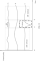
- FIG. 11 As shown in FIG. 11 , three curves A, B, and C respectively represent change statuses of channel quality in a period of time when three user equipments receive same multicast service data.
- A, B, and C are in a phase in which the channel quality is relatively good, and an access network device sends the data to A, B, and C in a multicast manner.
- relatively strong deterioration occurs in the channel quality of the user equipment C. The channel quality deterioration may be caused by movement, temporary signal blocking, interference, or the like, and consequently, it cannot be ensured that the multicast service data is correctly received.
- Receiving of the multicast service data in the unicast manner may be adjusted through hybrid automatic retransmission (hybrid automatic repeat request, HARQ), dynamic scheduling, or adaptive modulation and coding (adaptive modulation and coding, AMC), to compensate for the deterioration of the channel condition of the user equipment. Therefore, in the time period t1 to t2, the user equipment A and the user equipment B may continue to receive the multicast service data in the multicast manner, and the user equipment C may receive the multicast service data in the unicast manner. After a moment t2, the channel quality of the user equipment C is restored to a relatively good state, and the user equipment C may receive the multicast service data in the multicast manner again.
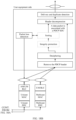
- a specific procedure may be shown in FIG. 12 , and includes the following steps.
- multicast configuration information and unicast configuration information may be sent at a time, and a multicast radio bearer or a unicast radio bearer may be selected for the radio bearer.
- the user equipment sends a channel measurement feedback to an access network device.
- the channel quality feedback carries information about channel quality of the user equipment, and may be specifically a measurement report, a channel status report, or an uplink reference signal.
- a switching threshold may be specified in the configuration information. Therefore, if the user equipment determines whether to switch a manner of receiving multicast service data, the user equipment may also send receiving manner switching indication information in this step.
- the access network device may determine, based on the channel measurement feedback sent by the user equipment or the receiving manner switching indication information sent by the user equipment, that the user equipment switches from receiving the multicast service data in a multicast manner to receiving the multicast service data in a unicast manner, or switches from receiving the multicast service data in a multicast manner to receiving the multicast service data in a unicast manner.
- the access network device sends a switching instruction to the user equipment, and the user equipment switches the manner of receiving the service data.
- the access network device determines that the user equipment C switches from receiving the multicast service data in the multicast manner to receiving the multicast service data in the unicast manner; and at the moment t2, the access network device determines that the user equipment C switches from receiving the multicast service data in the unicast manner to receiving the multicast service data in the multicast manner.
- the access network device may instruct, by using signaling, the user equipment C to switch from receiving the multicast service data in the multicast manner to receiving the multicast service data in the unicast manner.
- the manner of receiving the multicast service data by the user equipment may be switched through radio bearer reconfiguration.
- the access network device sends both the multicast configuration information and the unicast configuration information to the user equipment.
- the access network device instructs, by using the switching instruction, the user equipment to switch the manner of receiving the multicast service data, or activates a specified manner of receiving the multicast service data.
- the switching instruction may be, for example, sent by using a physical layer downlink control indicator (downlink control indicator, DCI) or a MAC layer control element (control element, CE).
- a manner of receiving multicast service data by user equipment may switch between a multicast manner and a unicast manner.
- the multicast service data needs to be sent to the user equipment in the unicast manner, and subsequently, the user equipment may receive the multicast service data in the multicast manner.
- FIG. 13 shows a scenario in which a service triggers switching of a receiving manner. Because in a multicast manner, sending and receiving are usually performed at a fixed rate, if user equipment has a specific requirement, for example, needs to receive multicast service data at a higher rate, the user equipment may interact with an access network device by using signaling, and the access network device sends the multicast service data to the user equipment in a unicast manner. As shown in the scenario marked in FIG. 12 , the user equipment is receiving a video service.
- image frames are organized by using a sequence as a unit, and there are an I-frame, a B-frame, and a P-frame, where the I-frame is a full-frame compressed coded frame, and a complete image can be reconstructed during decoding by using only data of the I-frame.
- the B-frame and the P-frame are based on the I-frame and only a part that is different from the I-frame is transmitted. In video information, there is much same information between consecutive frames. Therefore, transmission of the same information can be reduced by using the B-frame/P-frame, thereby saving a transmission bandwidth.
- an I-frame needs to be decoded first to successfully play the new video.
- a server In a unicast service, a server always sends data starting from an I-frame.
- data is sent to a plurality of users at a same time, a newly joined user cannot ensure that when the user joins the multicast service, the user can receive a new I-frame. As shown in FIG.
- the user equipment starts to receive the multicast service data at a moment T1, and at this moment, a previous I-frame has been sent, a next I-frame is not sent, and the user equipment cannot correctly construct a complete video frame based on a P-frame and a B-frame that are currently received. Therefore, the user equipment can be only in a black screen state, and cannot immediately start to play a video.
- the user equipment may instruct the access network device to send the multicast service data in the unicast manner, to send, at a relatively high rate, an I-frame and the B-frame that are not received before, so that the user equipment can immediately start to play the video.
- the user equipment may release a unicast resource, and switch back to the multicast manner to receive the multicast service data.
- a core network device may distinguish between data packets of different types by using tags in headers of the data packets, and the access network device may send the multicast service data based on indication information of the core network device, and buffer the multicast service data for a time.
- the access network device may first send a segment of the multicast service data in the unicast manner.
- the multicast service data may be buffered by the access network device previously, and a sent start data packet may be within a period of time or start from a latest special type of data packet.
- the multicast service data sent in the unicast manner may be sent by the core network device to the access network device.
- a unicast sending channel is established between the core network device and the access network device, to send the multicast service data.
- the access network device or the user equipment switches back to the multicast manner to receive the multicast service data.
- a core network may notify an access network of when to end sending of the multicast service data in the unicast manner, and separate signaling or a special identifier (for example, an end marker of a GTP-U) in a data packet may be used to indicate that sending of the multicast service data in the unicast manner ends.
- the access network device may also instruct, by using dedicated signaling or an end data packet identifier, the user equipment to switch back to the multicast manner to receive the multicast service data.
- a video playing scenario is used as an example. For a specific process, refer to FIG. 14 . The process includes the following steps.
- the user equipment may be user equipment that newly joins the multicast group, or may be existing user equipment in the multicast group.
- An access network device determines that a part of the multicast service data needs to be sent to the user equipment in a unicast manner, and establishes a radio bearer with the user equipment, to send the multicast service data in the unicast manner.
- a manner in which the access network device determines that the multicast service data needs to be sent to the user equipment in the unicast manner may include: specifying, by a core network device in protocol headers of data packets, that some data packets, such as a B-frame and a P-frame, need to be sent in the unicast manner; or the access network device parses a received data packet, and if finding that the data packet is a B-frame or a P-frame, the access network device determines that the data packet needs to be sent in the unicast manner.
- the access network device sends, to the user equipment, the multicast service data that needs to be sent in the unicast manner.
- the multicast service data sent by the access network device in the unicast manner may be buffered by the access network device. For example, during a process of performing a multicast service, the access network device buffers a recently sent I-frame and data between the I-frame and a next I-frame that is not received, and uses the buffered data as the multicast service data that needs to be sent in the unicast manner.
- the multicast service data may be data obtained from a source end of the multicast service. How to specifically obtain the multicast service data that needs to be sent in the unicast manner is not uniquely described in this embodiment of the present invention.
- the access network device After sending the multicast service data that needs to be sent in the unicast manner, the access network device switches the radio bearer between the access network device and the user equipment back to the radio bearer used to receive the multicast service data in the multicast manner.
- a switching manner may be sending, by the access network device, a switching instruction to the user equipment, or may be reconfiguring the radio access bearer, to enable a newly established radio bearer to be adapted to send the service data in the multicast manner.
- the access network device sends the multicast service data to the user equipment in the multicast manner.
- user equipment may notify, by using a data packet number, an access network device of a data packet that starts to be sent in the unicast manner.
- the access network device may be notified of a sequence number of a last successfully received data packet, or a sequence number of a next data packet that needs to be received; or the access network device may be notified by using a PDCP status report, where the PDCP status report is used to indicate that in data packets from a sequence number N to a sequence number M, an identifier of a data packet that is successfully received by the user equipment is 1, and an identifier of a data packet that is not successfully received is 0.
- the access network device sends, in the unicast manner, a data packet that is not received by the user equipment, to ensure service continuity of the user equipment.
- the unicast manner and the multicast manner can be switched to each other and can cooperate with each other.
- multicast service data is transmitted in the multicast manner without feedback information, and cannot be retransmitted. Therefore, a multicast service can be transmitted only in a relatively conservative robust transmission manner, to ensure that a terminal can successfully receive the multicast service data once in most scenarios. Because the conservative transmission manner needs to sacrifice resource efficiency, in the multicast enhancement solution of this application, a feedback mechanism of user equipment participating in a multicast service may be introduced. After the user equipment in a multicast group fails to receive multicast service data, an access network device retransmits the multicast service data. In this embodiment of the present invention, the multicast service data may be retransmitted in the unicast manner.
- each of A, B, and C represents user equipment in a multicast group.
- Channel quality of the user equipment C deteriorates from T1 to T2, for example, the user equipment C enters a cell edge or a channel is blocked, so that the user equipment C fails to receive multicast service data.
- the user equipment C may notify, by using feedback information, an access network device of a data packet that needs to be retransmitted.
- the user equipment may receive the multicast service data in both a multicast manner and a unicast manner. With assistance of the unicast manner, reliability of the multicast manner can be higher, and the multicast service data can be sent in a more efficient multicast manner.
- a manner in which the user equipment notifies the access network of the data packet that needs to be retransmitted may be specifically as follows:
- the user equipment specifies, by using a fixed relationship between feedback information and a retransmitted data packet, for example, a manner of sending a NACK by using a physical layer feedback channel, that the access network device retransmits, in the unicast manner, a data packet sent in an (n-k) th subframe, where n is a subframe for sending the NACK.
- the user equipment may explicitly indicate, by using an explicit data packet number, for example, an RLC or PDCP status report, that one or more data packets whose sequence numbers are (sequence number x, SNx) needs to be retransmitted.
- FIG. 17 and FIG. 18A and FIG. 18B show protocol stack structures for implementing multicast and unicast cooperation at a PDCP layer, including a protocol stack structure on a transmit side of a multicast user plane of an access network device and a protocol stack structure in which user equipment 1 to user equipment n are used as a receive side.
- a service interface of an RLC layer refer to multicast- and unicast-related protocol specifications, and details are not described herein again.
- the access network device establishes multicast bearers for different multicast sessions, and each multicast bearer corresponds to one multicast PDCP layer. Mapping function entities from various services to the bearer may be further added before the PDCP layer. For example, in 5G, there is an SDAP (service data adaptation protocol, service data adaptation protocol) layer above the PDCP layer, and the SDAP layer is used for mapping from a flow (flow) to the PDCP layer, and is irrelevant to a function of core content in this embodiment of the present invention, so that descriptions are omitted subsequently.
- the multicast PDCP adds a sequence number (sequence number, SN) to the multicast service SDU, and the SN is used by a receive side for data packet sorting and retransmission requests.
- the multicast PDCP layer can further encrypt a multicast data packet.
- the multicast PDCP layer uses a service encryption key instead of a terminal encryption key, to ensure that different users can decrypt the multicast PDCP layer.
- the PDCP layer may also perform header compression on a header of the data packet. Then, a PDCP header is added to the data packet, and the data packet with the PDCP header is sent to a replication and routing module.
- a data packets sent in the unicast manner at a bottom layer can be replicated and then buffered to a queue for processing a subsequent retransmission request. A data packet sent in the multicast manner may not need to be replicated and buffered.
- the PDCP layer After processing the data packet, the PDCP layer sends obtained packet data unit (packet data unit, PDU) data to an RLC module. Because feedback cannot be performed in the multicast manner, a multicast RLC entity may further map the data to a multicast MAC entity at the bottom layer by using a UM mode, and send, by using an independent HARQ entity and an independent scheduling identifier (such as a G-RNTI), the data on a multicast physical channel provided by a corresponding multicast physical layer. For user equipment in a unicast state, the multicast PDCP layer may send, based on member information of a multicast group, the data to a unicast RLC entity that is associated with a multicast service and that is of the corresponding user equipment.
- packet data unit packet data unit
- the RLC entity may select an AM mode or the UM mode, and then the RLC entity of the user equipment sends the data to a unicast MAC entity.
- the unicast HARQ entity of the user equipment is responsible for unicast scheduling, and sending HARQ data at a unicast physical layer.
- the user equipment may use the unicast manner or the multicast manner, or may use a hybrid mode in which both the unicast manner and the multicast manner work.
- the user equipment may receive the data packet by using the multicast RLC entity or the unicast RLC entity based on a configuration of the access network device, and then deliver the data packet to the multicast PDCP layer.
- the hybrid mode the multicast RLC entity and the unicast RLC entity may simultaneously submit the PDU data to the multicast PDCP layer, and the PDCP layer sorts or repeatedly determines, based on the SN, the PDU data submitted by the RLC entity.
- the PDCP layer may initiate a retransmission request, for example, notify the access network device of a missing data packet SN number by using a PDCP status report.
- the retransmission request is fed back to a unicast RLC entity corresponding to the access network device in the unicast manner, and is submitted by the unicast RLC entity of the access network device to the multicast PDCP layer.
- the multicast PDCP layer retransmits the PDU data with the corresponding SN by using the unicast RLC entity. In this way, data retransmission is complete.
- FIG. 19 shows a protocol stack structure in which a multicast manner and a unicast manner are switched at an RLC layer.
- a multicast RLC entity is responsible for segmenting a data packet, and then sends the data packet to a multicast MAC entity for sending.
- the multicast RLC entity replicates PDU data and sends the PDU data to a unicast MAC HARQ entity corresponding to the user equipment for unicast sending.
- an ARQ entity of the user equipment initiates an RLC status report, to request a multicast RLC entity of an access network device to retransmit PDU data corresponding to a missing RLC SN identifier.
- retransmission initiated by the multicast RLC entity may be performed at an RLC PDU granularity, thereby avoiding retransmission of entire PDCP PDU data.
- the entire PDCP PDU data is usually retransmitted at an IP packet granularity, and the multicast RLC entity may segment the multicast PDCP PDU data into several segments based on a resource status of an air interface, so that a problem of a waste of retransmission resources caused by a large retransmission granularity is avoided.
- the multicast RLC entity may further segment, based on a current radio resource status of the user equipment, the RLC PDU data again that needs to be retransmitted.
- the embodiments of the present invention may be applied to various radio access standards, and cooperation between the multicast manner and the unicast manner is implemented based on the PDCP layer, so that, for example, LTE multicast, NR unicast, LTE multicast, or WLAN unicast is implemented.
- An embodiment of the present invention further provides an access network device.
- the access network device includes:
- the access network device further includes: a configuration sending unit 2003, configured to send configuration information to the user equipment, where the configuration information is used to receive the multicast service data.
- the configuration information includes: at least one of configuration information of a multicast bearer, multicast session information corresponding to the multicast bearer, logical channel information of the multicast bearer, multicast scheduling identifier information, information about a transmission channel for sending the multicast service data in the multicast manner, information about a transmission channel for sending the multicast service data in the unicast manner, multicast logical channel information, measurement configuration information of the transmission channel of the multicast service data, and multicast-associated unicast configuration information.
- the access network device further includes: an information receiving unit 2004, configured to receive multicast service information sent by the user equipment or a core network device, where the multicast service information is used to instruct the user equipment to receive the multicast service data, and the multicast service information includes identifier information of the user equipment and identifier information of a multicast service.
- an information receiving unit 2004, configured to receive multicast service information sent by the user equipment or a core network device, where the multicast service information is used to instruct the user equipment to receive the multicast service data, and the multicast service information includes identifier information of the user equipment and identifier information of a multicast service.
- that the information receiving unit 2004 is configured to receive multicast service information sent by the user equipment or a core network device includes:
- the access network device further includes:
- the configuration information includes first multicast configuration information and second multicast configuration information; and the indication information indicates that the manner of receiving the multicast service data includes the multicast manner, and the indication information indicates that the first multicast configuration information or the second multicast configuration information is used to receive the multicast service data.
- the at least one data packet is multicast service data that has been sent in the multicast manner and that is buffered in the access network device, or multicast service data that has been sent in the multicast manner and that is received from a multicast service data source.
- the access network device further includes:
- the data sending unit 2002 is configured to: send to-be-sent multicast service data to a unicast radio link control RLC entity by using a packet data convergence protocol PDCP layer, and send the to-be-sent multicast service data in the unicast manner.
- the data sending unit 2002 is further configured to: replicate the to-be-sent multicast service data at the packet data convergence protocol PDCP layer, and store the to-be-sent multicast service data.
- the data sending unit 2002 is configured to: send to-be-sent multicast service data to a multicast radio link control RLC entity by using a multicast packet data convergence protocol PDCP layer, where the multicast radio link control RLC entity sends the to-be-sent multicast service data to a unicast medium access control MAC entity, and the unicast medium access control MAC entity sends the to-be-sent multicast service data in the unicast manner.
- PDCP layer multicast packet data convergence protocol
- An embodiment of the present invention further provides user equipment.
- the user equipment includes:
- the user equipment further includes: a configuration receiving unit 2103, configured to receive configuration information sent by the access network device, where the configuration information is used to receive the multicast service data.
- the configuration information includes: at least one of configuration information of a multicast bearer, multicast session information corresponding to the multicast bearer, logical channel information of the multicast bearer, multicast scheduling identifier information, information about a transmission channel for sending the multicast service data in the multicast manner, information about a transmission channel for sending the multicast service data in the unicast manner, multicast logical channel information, measurement configuration information of the transmission channel of the multicast service data, and multicast-associated unicast configuration information.
- the user equipment further includes: an information sending unit 2104, configured to send multicast service information to the access network device, where the multicast service information is used to instruct the user equipment to receive the multicast service data, and the multicast service information includes identifier information of the user equipment and identifier information of a multicast service.
- an information sending unit 2104 configured to send multicast service information to the access network device, where the multicast service information is used to instruct the user equipment to receive the multicast service data, and the multicast service information includes identifier information of the user equipment and identifier information of a multicast service.
- that the information sending unit 2104 is configured to send multicast service information to the access network device includes: sending multicast member change information to the access network device.
- the configuration information includes first multicast configuration information and second multicast configuration information; and the indication information indicates that the manner of receiving the multicast service data includes the multicast manner, and the indication information indicates that the first multicast configuration information or the second multicast configuration information is used to receive the multicast service data.
- the user equipment further includes: an indication sending unit 2105, configured to instruct the access network device to send at least one data packet in the multicast service data in the unicast manner.
- the user equipment further includes:
- the status sending unit 2106 is further configured to perform packet loss detection at a packet data convergence protocol PDCP layer to obtain the receiving status information.
- the data receiving unit 2102 is further configured to send, at a unicast radio link control RLC entity, the received multicast service data to the multicast packet data convergence protocol PDCP layer.
- FIG. 22 shows a device 220 according to an embodiment of the present invention.
- the device 220 includes a processor 2201, a memory 2202, and a transceiver 2203.
- the processor 2201, the memory 2202, and the transceiver 2203 are connected to each other by using a bus.
- the memory 2202 includes but is not limited to a random access memory (random access memory, RAM), a read-only memory (read-only memory, ROM), an erasable programmable read-only memory (erasable programmable read only memory, EPROM), or a compact disc read-only memory (compact disc read-only memory, CD-ROM).
- the memory 2202 is configured to store a related instruction and related data.
- the transceiver 2203 is configured to receive and send data.
- the processor 2201 may be one or more central processing units (central processing unit, CPU).
- CPU central processing unit
- the CPU may be a single-core CPU or a multi-core CPU.
- the processor 2201 in the device 220 is configured to read program code stored in the memory 2202,
- the memory 2202 stores program code.
- the processor 2201 is configured to read the program code, and cooperate with the transceiver 2203 to implement any method performed by the access network device or the user equipment according to any one of the embodiments of the present invention.
- the transceiver 2203 may implement functions of various units that implement reception and transmission functions in the foregoing user equipment or the access network device, and another function is implemented by the processor 2201.
- FIG. 23 shows user equipment 230 according to some embodiments of this application.
- the user equipment 230 may include input/output modules (including an audio input/output module 2318, a key input module 2316, a display 2320, and the like), a user interface 2302, one or more processors 2304, a transmitter 2306, a receiver 2308, a coupler 2310, an antenna 2314, and a memory 2312. These components may be connected by using a bus or in another manner. In FIG. 23 , an example in which the components are connected by using a bus is used.
- the antenna 2314 may be configured to convert electromagnetic energy into an electromagnetic wave in free space, or convert an electromagnetic wave in free space into electromagnetic energy in a transmission line.
- the coupler 2310 is configured to divide a mobile communications signal received by the antenna 2314 into a plurality of signals, and allocate the plurality of signals to a plurality of receivers 2308.
- the receiver 2308 may be configured to receive a mobile communications signal received by the antenna 2314.
- the transmitter 2306 and the receiver 2308 may be considered as a wireless modem.
- the user equipment 230 there may be one or more transmitters 2306 and one or more receivers 2308.
- the input/output modules may be configured to implement interaction between the user equipment 230 and a user/an external environment, and may mainly include the audio input and output module 2318, the key input module 2316, the display 2320, and the like. Specifically, the input/output modules may further include a camera, a touchscreen, a sensor, and the like. All the input/output modules communicate with the processor 2304 by using the user interface 2302.
- the memory 2312 is coupled to the processor 2304, and is configured to store various software programs and/or a plurality of sets of instructions.
- the memory 2312 may include a high-speed random access memory, and may include a non-volatile memory, for example, one or more magnetic disk storage devices, a flash memory device, or another non-volatile solid-state storage device.
- the memory 2312 may store an operating system (briefly referred to as a system below), for example, an embedded operating system such as Android, iOS, Windows, or Linux.
- the memory 2312 may further store a network communications program.
- the network communications program may be configured to communicate with one or more additional devices, one or more user equipments, or one or more network devices.
- the memory 2312 may further store a user interface program.
- the user interface program may vividly display content of an application program by using a graphical operation interface, and receive control operations of a user for the application program by using input controls such as a menu, a dialog box, and a key.
- the memory 2312 may be configured to store a program for implementing, on a side of the user equipment 230, the system message receiving method according to one or more embodiments of this application.
- the system message receiving method according to one or more embodiments of this application refer to subsequent embodiments.
- the processor 2304 may be configured to read and execute a computer-readable instruction. Specifically, the processor 2304 may be configured to: invoke a program stored in the memory 2312, and execute an instruction included in the program, to implement the method in subsequent embodiments.
- the user equipment 230 may be user equipment in the communications system described above in the embodiments of the present invention, and may be implemented as a mobile device, a mobile station (mobile station), a mobile unit (mobile unit), a radio unit, a remote unit, a user agent, a mobile client, or the like.
- the user equipment 230 shown in FIG. 23 is merely an implementation of the embodiments of this application. In an actual application, the user equipment 230 may include more or fewer components, and this is not limited herein.
- the processor 23 may correspond to the processor shown in FIG. 22 .
- the transmitter 2306 and the receiver 2308 may respectively correspond to units for implementing a transmission function and a reception function.
- An embodiment of the present invention further provides a storage medium.
- the storage medium stores program code, and the program code includes a program instruction.
- the processor cooperates with a transceiver to perform the foregoing method according to any one of the embodiments of the present invention.
- An embodiment of the present invention further provides a computer program product.
- the computer program product includes a program instruction.
- the program code is executed by a processor, the processor cooperates with a transceiver to perform the foregoing method according to any one of the embodiments of the present invention.
- the program may be stored in a computer-readable storage medium.
- the foregoing storage medium includes: any medium that can store program code, such as a ROM or a random access memory RAM, a magnetic disk, or an optical disc.
Landscapes
- Engineering & Computer Science (AREA)
- Computer Networks & Wireless Communication (AREA)
- Signal Processing (AREA)
- Multimedia (AREA)
- Mobile Radio Communication Systems (AREA)
- Data Exchanges In Wide-Area Networks (AREA)
Claims (14)
- Kommunikationsverfahren, das von einer Zugangsnetzwerkvorrichtung durchgeführt wird, wobei das Verfahren die folgenden Schritte umfasst:• Senden von Angabeinformationen an ein Benutzergerät, wobei die Angabeinformationen verwendet werden, um eine Empfangsmethode für Multicastservicedaten eines Multicastservices anzugeben, und die Empfangsmethode eine Unicastmethode, eine Multicastmethode oder eine Hybridmethode umfasst, wobei die Hybridmethode die Unicastmethode und die Multicastmethode umfasst;• wenn die Angabeinformationen angeben, dass die Empfangsmethode für die Multicastservicedaten die Unicastmethode ist, Senden der Multicastservicedaten an eine Unicast-Funkverbindungssteuerungseinheit, Unicast-RLC-Einheit, in der Zugangsnetzwerkvorrichtung durch eine Multicast-Paketdatenkonvergenzprotokoll-Schicht, Multicast-PDCP-Schicht, und Senden der Multicastservicedaten nach der Unicastmethode an das Benutzergerät;• wenn die Angabeinformationen angeben, dass die Empfangsmethode für die Multicastservicedaten die Multicastmethode ist, Senden der Multicastservicedaten an eine Multicast-RLC-Einheit in der Zugangsnetzwerkvorrichtung durch die Multicast-PDCP-Schicht und Senden der Multicastservicedaten nach der Multicastmethode an das Benutzergerät; und• wenn die Angabeinformationen angeben, dass die Empfangsmethode für die Multicastservicedaten die Hybridmethode ist:o Senden der Multicastservicedaten an die Multicast-RLC-Einheit und die Unicast-RLC-Einheit in der Zugangsnetzwerkvorrichtung durch die Multicast-PDCP-Schicht und Senden der Multicastservicedaten nach der Multicastmethode und der Unicastmethode an das Benutzergerät.
- Verfahren nach Anspruch 1, wobei die Hybridmethode ferner einen Neuübertragungsmechanismus beinhaltet, wobei der Neuübertragungsmechanismus die folgenden Verfahrensschritte beinhaltet:o Empfangen einer negativen Bestätigung, NACK, über einen Rückmeldekanal der physischen Schicht vom Benutzergerät oder Empfangen eines RLC-Statusberichts vom Benutzergerät oder Empfangen eines PDCP-Statusberichts vom Benutzergerät,• wobei die NACK ein Datenpaket der erneut zu übertragenden Multicastservicedaten angibt, und• wobei sowohl der RLC-Statusbericht als auch der PDCP-Statusbericht eine Sequenznummer, SN, eines erneut zu übertragenden Datenpakets der Multicastservicedaten angibt,o Bestimmen, basierend auf der empfangenen NACK, basierend auf dem empfangenen RLC-Statusbericht oder basierend auf dem empfangenen PDCP-Statusbericht, des erneut zu übertragenden Datenpakets der Multicastservicedaten; undo Neuübertragen, an das Benutzergerät nach der Unicastmethode, des von der NACK, dem RLC-Statusbericht oder dem PDCP-Statusbericht angegebenen Datenpakets.
- Verfahren nach Anspruch 1, wobei das Verfahren ferner Folgendes umfasst:o Senden von Konfigurationsinformationen an das Benutzergerät, wobei die Konfigurationsinformationen zum Empfangen der Multicastservicedaten verwendet werden, wobei die Konfigurationsinformationen mindestens eines von Folgendem umfassen:• Konfigurationsinformationen eines Multicastträgers,• Multicastsitzungsinformationen, die dem Multicastträger entsprechen,• logische Kanalinformationen des Multicastträgers und• Multicast-Planungskennungsinformationen.
- Verfahren nach einem der Ansprüche 1 bis 3, wobei das Verfahren ferner Folgendes umfasst:o Empfangen von Multicastserviceinformationen von einer Kernnetzwerkvorrichtung, wobei die Multicastserviceinformationen Kennungsinformationen des Benutzergeräts und Kennungsinformationen des Multicastservices umfassen.
- Verfahren nach einem der Ansprüche 1 bis 4, wobei die Multicast-RLC-Einheit einer Nicht-Bestätigungsmethode, UM-Methode, entspricht und die Unicast-RLC-Einheit einer Bestätigungsmethode, AM-Methode, oder der Nicht-Bestätigungsmethode, UM-Methode, entspricht.
- Verfahren nach einem der Ansprüche 1 bis 5, wobei:o das Senden der Multicastservicedaten an die Unicast-RLC-Einheit in der Zugangsnetzwerkvorrichtung durch die Multicast-PDCP-Schicht und das Senden der Multicastservicedaten nach der Unicastmethode an das Benutzergerät Folgendes umfasst:• Senden der Multicastservicedaten an die Unicast-RLC-Einheit über die Multicast-PDCP-Schicht,• Senden, durch die Unicast-RLC-Einheit, der Multicastservicedaten an eine Unicast-Medienzugriffssteuerungseinheit, Unicast-MAC-Einheit, und• Senden, durch die Unicast-MAC-Einheit, der Multicastservicedaten nach der Unicastmethode an das Benutzergerät;o das Senden der Multicastservicedaten an die Multicast-RLC-Einheit in der Zugangsnetzwerkvorrichtung durch die Multicast-PDCP-Schicht und das Senden der Multicastservicedaten nach der Multicastmethode an das Benutzergerät Folgendes umfasst:• Senden der Multicastservicedaten an die Multicast-RLC-Einheit in der Zugangsnetzwerkvorrichtung durch die Multicast-PDCP-Schicht,• Senden, durch die Multicast-RLC-Einheit, der Multicastservicedaten an eine Multicast-Medienzugriffssteuerungseinheit, Multicast-MAC-Einheit, und• Senden, durch die Multicast-MAC-Einheit, der Multicastservicedaten nach der Multicastmethode an das Benutzergerät; undo das Senden der Multicastservicedaten an die Multicast-RLC-Einheit und die Unicast-RLC-Einheit in der Zugangsnetzwerkvorrichtung durch die Multicast-PDCP-Schicht und das Senden der Multicastservicedaten nach der Unicastmethode und der Multicastmethode Folgendes umfasst:• Senden der Multicastservicedaten an die Multicast-RLC-Einheit und die Unicast-RLC-Einheit in der Zugangsnetzwerkvorrichtung durch die Multicast-PDCP-Schicht,• Senden, durch die Unicast-RLC-Einheit, der Multicastservicedaten an die Unicast-MAC-Einheit und Senden, durch die Unicast-MAC-Einheit, der Multicastservicedaten nach der Unicastmethode an das Benutzergerät und• Senden, durch die Multicast-RLC-Einheit, der Multicastservicedaten an die Multicast-MAC-Einheit und Senden, durch die Multicast-MAC-Einheit, der Multicastservicedaten nach der Multicastmethode an das Benutzergerät.
- Verfahren nach einem der Ansprüche 1 bis 6, wobei:das Senden der Multicastservicedaten nach der Unicastmethode Folgendes umfasst: Senden einer Unicast-Planungssignalisierung unter Verwendung einer Benutzergerätekennung, C-RNTI, wobei die Unicast-Planungssignalisierung Zeit-Frequenz-Ressourcen der Multicastservicedaten angibt; unddas Senden der Multicastservicedaten nach der Multicastmethode Folgendes umfasst: Senden einer Multicast-Planungssignalisierung unter Verwendung einer temporären Gruppenfunknetzkennung, G-RNTI, wobei die Multicast-Planungssignalisierung Zeit-Frequenz-Ressourcen der Multicastservicedaten angibt.
- Kommunikationsverfahren, das von einem Benutzergerät durchgeführt wird, wobei das Verfahren die folgenden Schritte umfasst:• Empfangen von Angabeinformationen von einer Zugangsnetzwerkvorrichtung, wobei die Angabeinformationen verwendet werden, um eine Empfangsmethode für Multicastservicedaten eines Multicastservices anzugeben, und die Empfangsmethode eine Unicastmethode, eine Multicastmethode oder eine Hybridmethode umfasst, wobei die Hybridmethode die Unicastmethode und die Multicastmethode umfasst;• wenn die Angabeinformationen angeben, dass die Empfangsmethode für die Multicastservicedaten die Unicastmethode ist, Empfangen der Multicastservicedaten von der Netzwerkvorrichtung nach der Unicastmethode und Senden der empfangenen Multicastservicedaten an eine Multicast-Datenkonvergenzprotokoll-Schicht, Multicast-PDCP-Schicht, über eine Unicast-Funkverbindungssteuerungseinheit, Unicast-RLC-Einheit;• wenn die Angabeinformationen angeben, dass die Empfangsmethode für die Multicastservicedaten die Multicastmethode ist, Empfangen der Multicastservicedaten von der Netzwerkvorrichtung nach der Multicastmethode und Senden der empfangenen Multicastservicedaten an die Multicast-PDCP-Schicht über eine Multicast-RLC-Einheit; und• wenn die Angabeinformationen angeben, dass die Empfangsmethode für die Multicastservicedaten die Hybridmethode ist:o Empfangen der Multicastservicedaten von der Zugangsnetzwerkvorrichtung nach der Multicastmethode und Senden der empfangenen Multicastservicedaten an die Multicast-PDCP-Schicht über die Multicast-RLC-Einheit; undo Empfangen der Multicastservicedaten von der Zugangsnetzwerkvorrichtung nach der Unicastmethode und Senden der empfangenen Multicastservicedaten an die Multicast-PDCP-Schicht über die Unicast-RLC-Einheit.
- Verfahren nach Anspruch 8, wobei die Hybridmethode ferner einen Neuübertragungsmechanismus beinhaltet, wobei der Neuübertragungsmechanismus die folgenden Verfahrensschritte beinhaltet:o Senden einer negativen Bestätigung, NACK, über einen Rückmeldekanal der physischen Schicht an die Zugangsnetzwerkvorrichtung oder Senden eines RLC-Statusberichts an die Zugangsnetzwerkvorrichtung oder Senden eines PDCP-Statusberichts an die Netzwerkvorrichtung,• wobei die NACK ein Datenpaket der erneut zu übertragenden Multicastservicedaten angibt, und• wobei sowohl der RLC-Statusbericht als auch der PDCP-Statusbericht eine Sequenznummer, SN, eines erneut zu übertragenden Datenpakets der Multicastservicedaten angeben, undo Empfangen des durch die NACK, den RLC-Statusbericht oder den PDCP-Statusbericht angegebenen Datenpakets von der Zugangsnetzwerkvorrichtung nach der Unicastmethode.
- Verfahren nach Anspruch 8 oder 9, wobei das Verfahren ferner Folgendes umfasst:o Empfangen von Konfigurationsinformationen von der Zugangsnetzwerkvorrichtung, wobei die Konfigurationsinformationen zum Empfangen der Multicastservicedaten verwendet werden, wobei die Konfigurationsinformationen mindestens eines von Folgendem umfassen:• Konfigurationsinformationen eines Multicastträgers,• Multicastsitzungsinformationen, die dem Multicastträger entsprechen,• logische Kanalinformationen des Multicastträgers und• Multicast-Planungskennungsinformationen.
- Zugangsnetzwerkvorrichtung, die dazu konfiguriert ist, eines der Verfahren nach den Ansprüchen 1 bis 7 durchzuführen.
- Benutzergerät, das dazu konfiguriert ist, eines der Verfahren nach den Ansprüchen 8 bis 10 durchzuführen.
- Computerlesbares Speichermedium, das Anweisungen umfasst, die, wenn die Anweisungen durch einen Computer einer Zugangsnetzwerkvorrichtung ausgeführt werden, die Zugangsnetzwerkvorrichtung dazu veranlassen, eines der Verfahren nach den Ansprüchen 1 bis 7 durchzuführen.
- Computerlesbares Speichermedium, das Anweisungen umfasst, die, wenn die Anweisungen durch einen Computer eines Benutzergeräts ausgeführt werden, das Benutzergerät dazu veranlassen, eines der Verfahren nach den Ansprüchen 8 bis 10 durchzuführen.
Priority Applications (1)
| Application Number | Priority Date | Filing Date | Title |
|---|---|---|---|
| EP24166130.5A EP4412259B1 (de) | 2017-12-28 | 2018-12-28 | Kommunikationsverfahren und zugehöriges produkt |
Applications Claiming Priority (2)
| Application Number | Priority Date | Filing Date | Title |
|---|---|---|---|
| CN201711453932.1A CN109982266B (zh) | 2017-12-28 | 2017-12-28 | 一种通信方法、及相关产品 |
| PCT/CN2018/124928 WO2019129212A1 (zh) | 2017-12-28 | 2018-12-28 | 一种通信方法、及相关产品 |
Related Child Applications (2)
| Application Number | Title | Priority Date | Filing Date |
|---|---|---|---|
| EP24166130.5A Division-Into EP4412259B1 (de) | 2017-12-28 | 2018-12-28 | Kommunikationsverfahren und zugehöriges produkt |
| EP24166130.5A Division EP4412259B1 (de) | 2017-12-28 | 2018-12-28 | Kommunikationsverfahren und zugehöriges produkt |
Publications (4)
| Publication Number | Publication Date |
|---|---|
| EP3723395A1 EP3723395A1 (de) | 2020-10-14 |
| EP3723395A4 EP3723395A4 (de) | 2020-10-28 |
| EP3723395B1 true EP3723395B1 (de) | 2024-10-02 |
| EP3723395C0 EP3723395C0 (de) | 2024-10-02 |
Family
ID=67063208
Family Applications (2)
| Application Number | Title | Priority Date | Filing Date |
|---|---|---|---|
| EP24166130.5A Active EP4412259B1 (de) | 2017-12-28 | 2018-12-28 | Kommunikationsverfahren und zugehöriges produkt |
| EP18897311.9A Active EP3723395B1 (de) | 2017-12-28 | 2018-12-28 | Kommunikationsverfahren und zugehöriges produkt |
Family Applications Before (1)
| Application Number | Title | Priority Date | Filing Date |
|---|---|---|---|
| EP24166130.5A Active EP4412259B1 (de) | 2017-12-28 | 2018-12-28 | Kommunikationsverfahren und zugehöriges produkt |
Country Status (8)
| Country | Link |
|---|---|
| US (4) | US11259361B2 (de) |
| EP (2) | EP4412259B1 (de) |
| JP (3) | JP7048745B2 (de) |
| KR (1) | KR102332981B1 (de) |
| CN (2) | CN109982266B (de) |
| AU (1) | AU2018396965C1 (de) |
| ES (1) | ES3053656T3 (de) |
| WO (1) | WO2019129212A1 (de) |
Cited By (1)
| Publication number | Priority date | Publication date | Assignee | Title |
|---|---|---|---|---|
| EP4179843A4 (de) * | 2020-07-13 | 2023-08-09 | Nec Corporation | Verfahren, vorrichtung und computerspeichermedium zur kommunikation |
Families Citing this family (116)
| Publication number | Priority date | Publication date | Assignee | Title |
|---|---|---|---|---|
| WO2019114938A1 (en) * | 2017-12-12 | 2019-06-20 | Nokia Solutions And Networks Oy | Method, system and apparatus for multicast session management in a 5g communication network |
| CN109982266B (zh) * | 2017-12-28 | 2021-05-11 | 华为技术有限公司 | 一种通信方法、及相关产品 |
| EP3913832A4 (de) * | 2019-03-22 | 2022-01-12 | Huawei Technologies Co., Ltd. | Kommunikationsverfahren, einrichtung, vorrichtung, system und speichermedium |
| US11284324B1 (en) * | 2019-07-15 | 2022-03-22 | Sprint Communications Company L.P. | Low-latency wireless data service in a fifth generation new radio (5GNR) network |
| CN112235731B (zh) * | 2019-07-15 | 2022-12-27 | 华为技术有限公司 | 一种通信方法、装置和系统 |
| CN115442822B (zh) * | 2019-07-22 | 2025-03-07 | 华为技术有限公司 | 通信方法和通信装置 |
| US11791943B2 (en) | 2019-07-26 | 2023-10-17 | Qualcomm Incorporated | Techniques for retransmissions in wireless communication systems |
| CN121013188A (zh) | 2019-07-31 | 2025-11-25 | 华为技术有限公司 | 一种通信方法及装置 |
| CN112312575B (zh) * | 2019-07-31 | 2025-10-03 | 华为技术有限公司 | 一种通信方法及装置 |
| CN112399633B (zh) * | 2019-08-12 | 2023-01-31 | 成都鼎桥通信技术有限公司 | 单播承载建立方法、装置及存储介质 |
| US11601805B2 (en) | 2019-08-26 | 2023-03-07 | Qualcomm Incorporated | 5G broadcast/multicast security |
| US11671824B2 (en) * | 2019-08-26 | 2023-06-06 | Qualcomm Incorporated | 5G broadcast/multicast security key refresh |
| EP4024911A4 (de) * | 2019-09-23 | 2022-11-23 | Huawei Technologies Co., Ltd. | Verfahren steuerung einer multicast-übertragung und zugehörige vorrichtung |
| WO2021056464A1 (zh) * | 2019-09-27 | 2021-04-01 | 华为技术有限公司 | 数据安全处理的方法和通信装置 |
| WO2021062708A1 (zh) * | 2019-09-30 | 2021-04-08 | Oppo广东移动通信有限公司 | 无线通信方法和终端设备 |
| US20210105196A1 (en) * | 2019-10-04 | 2021-04-08 | Huawei Technologies Co., Ltd. | Support group communications with shared downlink data |
| US11553457B2 (en) * | 2019-10-18 | 2023-01-10 | Qualcomm Incorporated | Coordination between multicast/broadcast communication and unicast communication |
| WO2021081871A1 (en) * | 2019-10-31 | 2021-05-06 | Zte Corporation | Adaptive data radio bearer mapping for multicast/broadcast in wireless networks |
| CN114467360B (zh) | 2019-11-06 | 2025-01-17 | 华为技术有限公司 | 会话建立的方法、数据传输的方法以及相关装置 |
| CN112788541B (zh) * | 2019-11-07 | 2022-06-07 | 成都鼎桥通信技术有限公司 | 一种3gpp组播场景的单播补建方法和装置 |
| CN115361656A (zh) | 2019-11-07 | 2022-11-18 | 华为技术有限公司 | 通信方法、装置及设备 |
| US11343083B2 (en) | 2019-11-22 | 2022-05-24 | Baidu Usa Llc | Method for key sharing between accelerators in virtual channel |
| US11405336B2 (en) | 2019-11-22 | 2022-08-02 | Baidu Usa Llc | Method for key sharing between accelerators in virtual channel with switch |
| US11558357B2 (en) | 2019-11-22 | 2023-01-17 | Baidu Usa Llc | Method for key sharing between accelerators with switch |
| US11552790B2 (en) | 2019-11-22 | 2023-01-10 | Baidu Usa Llc | Method for key sharing between accelerators |
| US11411934B2 (en) * | 2019-12-10 | 2022-08-09 | Baidu Usa Llc | System and method to securely broadcast a message to accelerators with switch |
| US11516010B2 (en) | 2019-12-10 | 2022-11-29 | Baidu Usa Llc | System and method to securely broadcast a message to accelerators using virtual channels |
| US11457354B2 (en) * | 2019-12-10 | 2022-09-27 | Baidu Usa Llc | System and method to securely broadcast a message to accelerators |
| US11728996B2 (en) * | 2019-12-10 | 2023-08-15 | Baidu Usa Llc | System and method to securely broadcast a message to accelerators using virtual channels with switch |
| US11210136B2 (en) | 2019-12-10 | 2021-12-28 | Baidu Usa Llc | Systems and methods for an operating system module for a data processing accelerator |
| EP4087363A4 (de) * | 2020-01-02 | 2023-01-11 | Guangdong Oppo Mobile Telecommunications Corp., Ltd. | Verfahren zur umschaltung des übertragungsmodus, elektronische vorrichtung und speichermedium |
| CN113067793B (zh) * | 2020-01-02 | 2022-08-12 | 维沃移动通信有限公司 | 多播业务的传输方法、传输处理方法及相关设备 |
| CN115023973B (zh) | 2020-01-03 | 2024-12-24 | 中兴通讯股份有限公司 | 用于管理多媒体广播多播服务(mbms)连续性的系统和方法 |
| JP7353502B2 (ja) | 2020-01-08 | 2023-09-29 | 中興通訊股▲ふん▼有限公司 | マルチキャスト/ブロードキャストサービスデータのためのシステムおよび方法 |
| EP4088405A4 (de) * | 2020-01-10 | 2023-10-11 | Qualcomm Incorporated | Broadcast-/multicast-kommunikation im gemischten modus |
| CN113163341B (zh) * | 2020-01-22 | 2026-01-27 | 北京三星通信技术研究有限公司 | 在无线通信系统中传输数据的方法和设备 |
| WO2021155584A1 (zh) * | 2020-02-07 | 2021-08-12 | Oppo广东移动通信有限公司 | 通信方式切换方法、装置及其设备 |
| WO2021159229A1 (en) * | 2020-02-10 | 2021-08-19 | Mediatek Singapore Pte. Ltd. | Methods and apparatus of multicast radio bearer establishment for nr multicast and broadcast services |
| CN113271551B (zh) * | 2020-02-17 | 2022-07-05 | 大唐移动通信设备有限公司 | 一种数据流传输方法、终端和网络侧设备 |
| CN113301509B (zh) * | 2020-02-21 | 2022-10-21 | 维沃移动通信有限公司 | 一种通信方法及相关设备 |
| WO2021177716A2 (ko) * | 2020-03-04 | 2021-09-10 | 엘지전자 주식회사 | 멀티캐스트와 관련된 통신 |
| CN111371488B (zh) * | 2020-03-13 | 2021-07-02 | 北京邮电大学 | 内容数据传输方法、装置及电子设备 |
| US12279334B2 (en) | 2020-03-20 | 2025-04-15 | Qualcomm Incorporated | Techniques for multicast and unicast convergence in wireless communications |
| CN113438692B (zh) | 2020-03-23 | 2023-10-27 | 维沃移动通信有限公司 | 传输模式转换指示方法、接入网设备及终端设备 |
| JP7516542B2 (ja) * | 2020-03-24 | 2024-07-16 | 中興通訊股▲ふん▼有限公司 | マルチキャスト/ブロードキャストサービス配信の動的変更 |
| CN113518315B (zh) * | 2020-03-27 | 2023-03-24 | 华为技术有限公司 | 一种配置无线承载的方法、装置及系统 |
| CN111432352B (zh) * | 2020-03-30 | 2022-03-22 | 深圳市信锐网科技术有限公司 | 一种报文传输方法、装置、设备及存储介质 |
| US20230354380A1 (en) * | 2020-04-03 | 2023-11-02 | Qualcomm Incorporated | Inter-operator multicast and unicast convergence transmission |
| EP4128996A1 (de) * | 2020-04-03 | 2023-02-08 | Shanghai Langbo Communication Technology Company Limited | Verfahren und vorrichtung zur verwendung in der drahtlosen kommunikation |
| CN113556687B (zh) * | 2020-04-23 | 2022-09-27 | 上海朗帛通信技术有限公司 | 一种被用于无线通信的方法和设备 |
| CN113573248B (zh) * | 2020-04-28 | 2023-06-20 | 华为技术有限公司 | 用于传输数据的方法与装置 |
| CN113630824B (zh) * | 2020-05-08 | 2026-01-30 | 华为技术有限公司 | 业务切换方法、装置及系统 |
| CN115606124B (zh) * | 2020-05-14 | 2025-02-25 | 中兴通讯股份有限公司 | 用于管理针对多播传输的反馈的系统和方法 |
| CN113676846B (zh) * | 2020-05-15 | 2023-04-11 | 大唐移动通信设备有限公司 | 一种传输方式确定方法、装置、设备及存储介质 |
| AU2020395266B2 (en) * | 2020-05-19 | 2023-10-12 | Zte Corporation | Methods and systems for multicast and broadcast service establishment in wireless communication networks |
| CN113709763B (zh) | 2020-05-20 | 2025-02-25 | 展讯通信(上海)有限公司 | 接入控制方法及装置、存储介质、终端 |
| KR20210147717A (ko) * | 2020-05-29 | 2021-12-07 | 삼성전자주식회사 | 차세대 이동 통신 시스템에서 멀티캐스트를 지원하는 베어러 구조와 지원 방법 및 장치 |
| CN113784400B (zh) * | 2020-06-10 | 2022-12-13 | 中国移动通信有限公司研究院 | 切换方法、处理方法、装置、网络设备及核心网设备 |
| KR20210154639A (ko) * | 2020-06-12 | 2021-12-21 | 삼성전자주식회사 | 무선 통신 시스템에서 mbs를 지원하는 방법 및 장치 |
| WO2022006882A1 (zh) * | 2020-07-10 | 2022-01-13 | Oppo广东移动通信有限公司 | Mbs业务的传输方法及装置、网络设备、终端设备 |
| CN115516881B (zh) * | 2020-07-10 | 2024-08-23 | Oppo广东移动通信有限公司 | 无线通信方法、终端设备和网络设备 |
| CN113938977A (zh) * | 2020-07-14 | 2022-01-14 | 维沃移动通信有限公司 | 数据传输方法、数据传输装置、网络侧设备及第一终端 |
| CN113938438B (zh) * | 2020-07-14 | 2023-10-13 | 维沃移动通信有限公司 | 数据处理方法、数据处理装置及第一终端 |
| WO2022016364A1 (en) | 2020-07-21 | 2022-01-27 | Mediatek Singapore Pte. Ltd. | Methods and apparatus of multicast and broadcast service reception |
| US20230292092A1 (en) * | 2020-07-22 | 2023-09-14 | Kt Corporation | Mbs data transmission method and device therefor |
| CN115956382B (zh) * | 2020-07-24 | 2025-05-13 | 联想(北京)有限公司 | 用于多播及广播服务的设备 |
| EP4184958B1 (de) | 2020-07-30 | 2025-09-10 | Huawei Technologies Co., Ltd. | Verfahren zur multicast-kommunikation sowie erste netzwerkvorrichtung und zweite netzwerkvorrichtung |
| CN116566551B (zh) * | 2020-07-31 | 2026-02-24 | Oppo广东移动通信有限公司 | 一种mbs业务传输方法及装置、终端设备、网络设备 |
| CN114070482B (zh) * | 2020-07-31 | 2023-04-07 | 大唐移动通信设备有限公司 | 业务传输的处理方法、装置、网络侧设备及终端 |
| CN114071805B (zh) * | 2020-08-03 | 2024-03-19 | 大唐移动通信设备有限公司 | 业务处理方法、信息指示方法、终端和网络设备 |
| EP4598235A3 (de) * | 2020-08-03 | 2025-10-15 | Kyocera Corporation | Kommunikationssteuerungsverfahren |
| EP4190024A4 (de) * | 2020-08-03 | 2024-04-24 | Qualcomm Incorporated | Mrb-architektur mit pdcp-neuübertragung |
| US12418838B2 (en) | 2020-08-04 | 2025-09-16 | Nokia Technologies Oy | CU-DU communication for multicast with support for switching between unicast and multicast |
| CN115379398B (zh) * | 2020-08-04 | 2024-06-07 | 大唐移动通信设备有限公司 | 单播多播转换方法、装置及处理器可读存储介质 |
| CN114071567B (zh) * | 2020-08-06 | 2024-04-23 | 中国移动通信有限公司研究院 | 数据传输方法、终端及网络节点 |
| WO2022027421A1 (en) * | 2020-08-06 | 2022-02-10 | Qualcomm Incorporated | Downlink control information for unicast scheduling of multiple user equipment |
| CN114071372B (zh) * | 2020-08-07 | 2023-04-07 | 大唐移动通信设备有限公司 | 多播广播业务mbs传输方法、终端及网络设备 |
| CN116134842A (zh) * | 2020-08-07 | 2023-05-16 | 捷开通讯(深圳)有限公司 | 用于多播/广播服务的设备和方法 |
| WO2022056857A1 (en) * | 2020-09-18 | 2022-03-24 | Nec Corporation | Methods, devices and computer readable media for communications |
| CN112153599B (zh) * | 2020-09-22 | 2023-03-24 | 中信科智联科技有限公司 | 一种消息的传输方法、装置、车联网设备及管理节点 |
| CN114339902B (zh) * | 2020-09-29 | 2024-06-18 | 北京紫光展锐通信技术有限公司 | 业务切换指示、接收方法及装置、存储介质、基站、终端 |
| WO2022073246A1 (zh) * | 2020-10-10 | 2022-04-14 | 华为技术有限公司 | 一种通信方法及装置 |
| EP4277382B1 (de) | 2020-10-22 | 2026-03-18 | Apple Inc. | Punkt-zu-punkt- und punkt-zu-mehrpunkt-umschaltung mit dienstkontinuität für broadcast- und multicast-dienst |
| CN114501340B (zh) * | 2020-10-23 | 2023-03-31 | 中国移动通信有限公司研究院 | Mbs接收方法、发送方法、装置、终端及基站 |
| CN114667786B (zh) | 2020-10-23 | 2024-12-31 | 上海诺基亚贝尔股份有限公司 | 下行链路控制和数据信道配置 |
| CN114501337B (zh) * | 2020-10-23 | 2023-08-15 | 大唐移动通信设备有限公司 | 一种分组数据汇聚协议状态上报、接收方法、终端及设备 |
| WO2022087990A1 (zh) * | 2020-10-29 | 2022-05-05 | Oppo广东移动通信有限公司 | 一种多播业务的重传方法及装置、终端设备、网络设备 |
| CN114513757B (zh) * | 2020-11-17 | 2024-05-10 | 维沃移动通信有限公司 | 信息获取方法、指示方法、装置、相关设备和存储介质 |
| CN114629608B (zh) * | 2020-12-11 | 2024-10-22 | 上海朗帛通信技术有限公司 | 一种被用于无线通信的通信节点中的方法和装置 |
| CN118869159B (zh) * | 2020-12-22 | 2026-02-06 | 北京小米移动软件有限公司 | 数据重传的方法、装置、通信设备及存储介质 |
| CN114765741B (zh) * | 2021-01-11 | 2024-10-18 | 中国移动通信有限公司研究院 | 一种业务的传输方法、网络设备及终端 |
| WO2022151248A1 (zh) | 2021-01-14 | 2022-07-21 | 华为技术有限公司 | 一种数据传输的方法与装置 |
| KR20230130684A (ko) * | 2021-01-14 | 2023-09-12 | 구글 엘엘씨 | PTP(point-to-point) 및 PTM(point-to-multipoint)전송 관리 |
| CN114928554B (zh) * | 2021-02-01 | 2024-04-02 | 大唐移动通信设备有限公司 | 视频传输方法、装置和存储介质 |
| CN114980089A (zh) * | 2021-02-22 | 2022-08-30 | 华为技术有限公司 | 组播或广播业务数据的安全保护方法及装置 |
| KR20230147066A (ko) * | 2021-02-25 | 2023-10-20 | 미쓰비시덴키 가부시키가이샤 | 통신 시스템 및 통신 단말 |
| US11622242B2 (en) | 2021-03-03 | 2023-04-04 | Nokia Technologies Oy | Machine learning based multicast user grouping |
| CN115038049B (zh) * | 2021-03-05 | 2024-01-23 | 维沃移动通信有限公司 | 多播业务的接收方法、配置方法、终端及网络侧设备 |
| WO2022198613A1 (zh) * | 2021-03-26 | 2022-09-29 | 华为技术有限公司 | 一种媒体数据传输方法及通信装置 |
| CN115550852A (zh) * | 2021-06-30 | 2022-12-30 | 中兴通讯股份有限公司 | 基于多播的资源分配方法、装置、基站、设备及存储介质 |
| KR102691816B1 (ko) * | 2021-09-07 | 2024-08-06 | 주식회사 엘지유플러스 | 무선 통신 시스템에서 멀티캐스트 서비스와 유니캐스트 서비스를 제공하는 방법 및 이를 위한 장치 |
| CN114009109A (zh) * | 2021-09-24 | 2022-02-01 | 北京小米移动软件有限公司 | 一种组播调度mbs业务的指示方法、装置 |
| EP4406196B1 (de) * | 2021-10-21 | 2025-07-30 | Google Llc | Verwaltung von multicast-datenkommunikation |
| JP7727846B2 (ja) * | 2021-10-21 | 2025-08-21 | グーグル エルエルシー | マルチキャストおよびユニキャストワイヤレスデータ送信の管理 |
| CN116170754B (zh) * | 2021-11-25 | 2026-01-30 | 维沃移动通信有限公司 | 通信业务的实现方法、装置及网络侧设备 |
| US20230246946A1 (en) * | 2022-01-28 | 2023-08-03 | Comcast Cable Communications, Llc | Methods and systems for multicast communication session management |
| CN114727235B (zh) * | 2022-03-29 | 2024-01-30 | 中国电信股份有限公司 | 组播业务处理方法、装置、存储介质及电子设备 |
| CN115348467B (zh) * | 2022-05-31 | 2024-08-02 | 青岛海信宽带多媒体技术有限公司 | 一种智能机顶盒及直播频道播放方法 |
| WO2024022904A1 (en) * | 2022-07-28 | 2024-02-01 | Canon Kabushiki Kaisha | Mbs multicast configuration |
| JP7782700B2 (ja) * | 2022-08-01 | 2025-12-09 | Ntt株式会社 | 通信システム、同報通信装置、通信方法及びプログラム |
| KR102911865B1 (ko) * | 2022-08-23 | 2026-01-12 | 에스케이텔레콤 주식회사 | 상공망용 기지국과 그 통신 방법 |
| US12432613B2 (en) * | 2022-10-07 | 2025-09-30 | Qualcomm Incorporated | Data scrambling in rate-split communications |
| CN120153708A (zh) * | 2022-11-11 | 2025-06-13 | 华为技术有限公司 | 通信方法和通信装置 |
| CN119316245A (zh) * | 2023-07-12 | 2025-01-14 | 华为技术有限公司 | 传输的方法、装置、设备和存储介质 |
| CN121603884A (zh) * | 2024-08-22 | 2026-03-03 | 上海华为技术有限公司 | 一种通信方法及通信装置 |
| WO2026065540A1 (zh) * | 2024-09-30 | 2026-04-02 | 北京小米移动软件有限公司 | 通信方法、终端、网络设备、系统和存储介质 |
Citations (1)
| Publication number | Priority date | Publication date | Assignee | Title |
|---|---|---|---|---|
| WO2015161787A1 (en) * | 2014-04-21 | 2015-10-29 | Huawei Technologies Co., Ltd. | System and method for servicing one or more user equipments through one or more streams |
Family Cites Families (38)
| Publication number | Priority date | Publication date | Assignee | Title |
|---|---|---|---|---|
| CN100355316C (zh) * | 2005-03-26 | 2007-12-12 | 华为技术有限公司 | 无线通信系统中广播多播区域管理的实现方法 |
| CN100421515C (zh) * | 2005-05-20 | 2008-09-24 | 华为技术有限公司 | 基于移动网络的组播业务数据的实现方法 |
| US11477617B2 (en) * | 2006-03-20 | 2022-10-18 | Ericsson Evdo Inc. | Unicasting and multicasting multimedia services |
| CN101132215B (zh) | 2006-08-25 | 2012-01-11 | 上海贝尔股份有限公司 | 演进多媒体广播多播业务基站、用户设备和方法 |
| CN101136759A (zh) * | 2006-09-01 | 2008-03-05 | 华为技术有限公司 | 一种多媒体广播组播业务的发送处理方法及系统 |
| CN101267593B (zh) * | 2007-03-15 | 2011-04-20 | 华为技术有限公司 | 对目标小区进行组播广播多媒体业务激活的方法及基站 |
| CN101299824B (zh) * | 2007-04-30 | 2011-04-13 | 华为技术有限公司 | 多媒体广播和组播业务数据的获取方法、系统和用户终端 |
| CN100502534C (zh) * | 2007-05-11 | 2009-06-17 | 中兴通讯股份有限公司 | 多媒体广播组播业务质量控制和调整方法 |
| CN101370156B (zh) * | 2007-08-15 | 2012-05-23 | 上海华为技术有限公司 | 多播组播业务传输的方法和网络系统 |
| CN101146255A (zh) * | 2007-08-21 | 2008-03-19 | 中兴通讯股份有限公司 | 一种整合广播组播业务和单播业务的方法及系统 |
| EP2362705A4 (de) | 2008-11-28 | 2014-04-09 | Fujitsu Ltd | Drahtlose kommunikationsvorrichtung, drahtloses kommunikationssystem und kommunikationsmodus-umschaltverfahren |
| CN102056082B (zh) * | 2009-11-05 | 2015-08-12 | 中兴通讯股份有限公司 | 多播广播业务配置信息发送方法及装置 |
| US8320292B2 (en) * | 2009-11-18 | 2012-11-27 | Motorola Mobility Llc | Method to control a multimedia broadcast multicast service(MBMS) mode of a MBMS session in a communication system |
| CN102149021B (zh) * | 2010-02-05 | 2013-09-25 | 华为技术有限公司 | 网络时移的处理方法、装置及系统 |
| US9936472B2 (en) | 2011-02-08 | 2018-04-03 | Qualcomm Incorporated | Method and apparatus for counting devices related to broadcast data services |
| US9226265B2 (en) | 2011-04-15 | 2015-12-29 | Qualcomm Incorporated | Demand-based multimedia broadcast multicast service management |
| CN102857873B (zh) * | 2011-06-30 | 2017-02-08 | 中兴通讯股份有限公司 | 基于td‑lte的宽带数字集群系统及其数据传输方法 |
| US8819264B2 (en) | 2011-07-18 | 2014-08-26 | Verizon Patent And Licensing Inc. | Systems and methods for dynamically switching between unicast and multicast delivery of media content in a wireless network |
| US9826502B2 (en) | 2011-07-25 | 2017-11-21 | Qualcomm Incorporated | Managing handoff triggering between unicast and multicast services |
| CN106850140B (zh) * | 2012-01-12 | 2020-04-28 | 华为终端有限公司 | 数据通信的方法、装置及系统 |
| CN103796170B (zh) * | 2012-11-02 | 2017-11-21 | 电信科学技术研究院 | 一种传输数据的方法、系统和设备 |
| US9445243B2 (en) | 2013-03-22 | 2016-09-13 | Mediatek Inc. | Service continuity for group communication over LTE eMBMS |
| CN104247470B (zh) * | 2013-04-09 | 2020-06-02 | 华为技术有限公司 | 数据传输方法、装置及系统 |
| WO2015061983A1 (en) | 2013-10-30 | 2015-05-07 | Qualcomm Incorporated | Service continuity for group communications over evolved multimedia broadcast multicast service |
| US20150358374A1 (en) * | 2014-06-04 | 2015-12-10 | Acer Incorporated | Method of Data Transmission in Multicast or Broadcast Service |
| CN105376717B (zh) * | 2014-08-25 | 2020-06-23 | 中兴通讯股份有限公司 | 建立lte集群通信承载的方法、用户设备及第一网元设备 |
| US10110713B2 (en) | 2014-09-12 | 2018-10-23 | Samsung Electronics Co., Ltd. | Handling different protocol data unit types in a device to device communication system |
| US20170251342A1 (en) * | 2014-10-02 | 2017-08-31 | Rajesh Bhalla | Group communication with a logical group of wireless devices operating in different networks |
| CN104540043A (zh) * | 2014-12-24 | 2015-04-22 | 北京邮电大学 | 一种无线网络的视频传输方法及基站 |
| CN106488409B (zh) * | 2015-08-29 | 2020-01-21 | 华为技术有限公司 | 一种单播发送广播多播数据的方法、装置及系统 |
| CN106604390B (zh) * | 2015-10-15 | 2020-08-04 | 中国移动通信集团公司 | 一种提供定位服务的方法、基站及终端 |
| US10044638B2 (en) * | 2016-05-26 | 2018-08-07 | 1Qb Information Technologies Inc. | Methods and systems for quantum computing |
| EP3461185A4 (de) * | 2016-06-30 | 2019-04-17 | Huawei Technologies Co., Ltd. | Netzwerkvorrichtung, endgerätevorrichtung, konfigurationsverfahren für multicast-dienst und empfangsverfahren |
| CN107734644A (zh) * | 2016-08-11 | 2018-02-23 | 株式会社Ntt都科摩 | 信息发送、接收和控制方法,发送设备、接收设备和基站 |
| CN113556823B (zh) * | 2017-01-06 | 2023-05-02 | 华为技术有限公司 | 信息传输方法、终端设备及接入网设备 |
| US10511548B2 (en) * | 2017-06-22 | 2019-12-17 | Nicira, Inc. | Multicast packet handling based on control information in software-defined networking (SDN) environment |
| CN109769150B (zh) | 2017-11-09 | 2021-02-23 | 华为技术有限公司 | 一种传输组播业务的方法和设备 |
| CN109982266B (zh) * | 2017-12-28 | 2021-05-11 | 华为技术有限公司 | 一种通信方法、及相关产品 |
-
2017
- 2017-12-28 CN CN201711453932.1A patent/CN109982266B/zh active Active
- 2017-12-28 CN CN202110522822.6A patent/CN113411755B/zh active Active
-
2018
- 2018-12-28 KR KR1020207021460A patent/KR102332981B1/ko active Active
- 2018-12-28 EP EP24166130.5A patent/EP4412259B1/de active Active
- 2018-12-28 AU AU2018396965A patent/AU2018396965C1/en active Active
- 2018-12-28 WO PCT/CN2018/124928 patent/WO2019129212A1/zh not_active Ceased
- 2018-12-28 EP EP18897311.9A patent/EP3723395B1/de active Active
- 2018-12-28 ES ES24166130T patent/ES3053656T3/es active Active
- 2018-12-28 JP JP2020535162A patent/JP7048745B2/ja active Active
-
2020
- 2020-06-23 US US16/909,891 patent/US11259361B2/en active Active
-
2022
- 2022-01-05 US US17/569,120 patent/US11758612B2/en active Active
- 2022-03-24 JP JP2022047814A patent/JP7513648B2/ja active Active
-
2023
- 2023-07-26 US US18/359,439 patent/US12150203B2/en active Active
-
2024
- 2024-06-27 JP JP2024103959A patent/JP7781964B2/ja active Active
- 2024-10-30 US US18/931,799 patent/US20250126679A1/en active Pending
Patent Citations (1)
| Publication number | Priority date | Publication date | Assignee | Title |
|---|---|---|---|---|
| WO2015161787A1 (en) * | 2014-04-21 | 2015-10-29 | Huawei Technologies Co., Ltd. | System and method for servicing one or more user equipments through one or more streams |
Cited By (1)
| Publication number | Priority date | Publication date | Assignee | Title |
|---|---|---|---|---|
| EP4179843A4 (de) * | 2020-07-13 | 2023-08-09 | Nec Corporation | Verfahren, vorrichtung und computerspeichermedium zur kommunikation |
Also Published As
Similar Documents
| Publication | Publication Date | Title |
|---|---|---|
| US12150203B2 (en) | Communication method and related product | |
| US12574803B2 (en) | Multicast-broadcast services mobility and service continuity | |
| US11864275B2 (en) | System for data transmission | |
| KR20230003065A (ko) | 베어러 구성 방법 및 장치, 컨텍스트 정보 관리 방법 및 장치, 해제 방법 및 장치, 설비 | |
| US20200351714A1 (en) | Communication Method for Deterministic Transmission and Related Apparatus | |
| CN113424620A (zh) | 跨LF和mmWave的服务连续性的方法和装置 | |
| US20230345323A1 (en) | Data transmission method and apparatus | |
| US20240080216A1 (en) | Methods and apparatuses for multicast and broadcast services | |
| RU2781562C2 (ru) | Способ связи и соответствующий продукт | |
| CN115918141B (zh) | 通信方法和通信装置 | |
| GB2640203A (en) | Method for managing data transmission in a communication network | |
| WO2025060874A1 (zh) | 一种数据传输方法、装置和通信系统 |
Legal Events
| Date | Code | Title | Description |
|---|---|---|---|
| STAA | Information on the status of an ep patent application or granted ep patent |
Free format text: STATUS: THE INTERNATIONAL PUBLICATION HAS BEEN MADE |
|
| PUAI | Public reference made under article 153(3) epc to a published international application that has entered the european phase |
Free format text: ORIGINAL CODE: 0009012 |
|
| STAA | Information on the status of an ep patent application or granted ep patent |
Free format text: STATUS: REQUEST FOR EXAMINATION WAS MADE |
|
| 17P | Request for examination filed |
Effective date: 20200707 |
|
| AK | Designated contracting states |
Kind code of ref document: A1 Designated state(s): AL AT BE BG CH CY CZ DE DK EE ES FI FR GB GR HR HU IE IS IT LI LT LU LV MC MK MT NL NO PL PT RO RS SE SI SK SM TR |
|
| AX | Request for extension of the european patent |
Extension state: BA ME |
|
| A4 | Supplementary search report drawn up and despatched |
Effective date: 20200928 |
|
| RIC1 | Information provided on ipc code assigned before grant |
Ipc: H04W 4/08 20090101AFI20200922BHEP |
|
| DAV | Request for validation of the european patent (deleted) | ||
| DAX | Request for extension of the european patent (deleted) | ||
| STAA | Information on the status of an ep patent application or granted ep patent |
Free format text: STATUS: EXAMINATION IS IN PROGRESS |
|
| 17Q | First examination report despatched |
Effective date: 20210713 |
|
| GRAP | Despatch of communication of intention to grant a patent |
Free format text: ORIGINAL CODE: EPIDOSNIGR1 |
|
| STAA | Information on the status of an ep patent application or granted ep patent |
Free format text: STATUS: GRANT OF PATENT IS INTENDED |
|
| INTG | Intention to grant announced |
Effective date: 20231201 |
|
| GRAJ | Information related to disapproval of communication of intention to grant by the applicant or resumption of examination proceedings by the epo deleted |
Free format text: ORIGINAL CODE: EPIDOSDIGR1 |
|
| STAA | Information on the status of an ep patent application or granted ep patent |
Free format text: STATUS: EXAMINATION IS IN PROGRESS |
|
| GRAP | Despatch of communication of intention to grant a patent |
Free format text: ORIGINAL CODE: EPIDOSNIGR1 |
|
| STAA | Information on the status of an ep patent application or granted ep patent |
Free format text: STATUS: GRANT OF PATENT IS INTENDED |
|
| INTC | Intention to grant announced (deleted) | ||
| INTG | Intention to grant announced |
Effective date: 20240422 |
|
| GRAS | Grant fee paid |
Free format text: ORIGINAL CODE: EPIDOSNIGR3 |
|
| GRAA | (expected) grant |
Free format text: ORIGINAL CODE: 0009210 |
|
| STAA | Information on the status of an ep patent application or granted ep patent |
Free format text: STATUS: THE PATENT HAS BEEN GRANTED |
|
| AK | Designated contracting states |
Kind code of ref document: B1 Designated state(s): AL AT BE BG CH CY CZ DE DK EE ES FI FR GB GR HR HU IE IS IT LI LT LU LV MC MK MT NL NO PL PT RO RS SE SI SK SM TR |
|
| REG | Reference to a national code |
Ref country code: GB Ref legal event code: FG4D |
|
| REG | Reference to a national code |
Ref country code: CH Ref legal event code: EP |
|
| REG | Reference to a national code |
Ref country code: DE Ref legal event code: R096 Ref document number: 602018075080 Country of ref document: DE |
|
| REG | Reference to a national code |
Ref country code: IE Ref legal event code: FG4D |
|
| U01 | Request for unitary effect filed |
Effective date: 20241002 |
|
| U07 | Unitary effect registered |
Designated state(s): AT BE BG DE DK EE FI FR IT LT LU LV MT NL PT RO SE SI Effective date: 20241023 |
|
| U20 | Renewal fee for the european patent with unitary effect paid |
Year of fee payment: 7 Effective date: 20250123 |
|
| PG25 | Lapsed in a contracting state [announced via postgrant information from national office to epo] |
Ref country code: IS Free format text: LAPSE BECAUSE OF FAILURE TO SUBMIT A TRANSLATION OF THE DESCRIPTION OR TO PAY THE FEE WITHIN THE PRESCRIBED TIME-LIMIT Effective date: 20250202 Ref country code: HR Free format text: LAPSE BECAUSE OF FAILURE TO SUBMIT A TRANSLATION OF THE DESCRIPTION OR TO PAY THE FEE WITHIN THE PRESCRIBED TIME-LIMIT Effective date: 20241002 |
|
| PG25 | Lapsed in a contracting state [announced via postgrant information from national office to epo] |
Ref country code: ES Free format text: LAPSE BECAUSE OF FAILURE TO SUBMIT A TRANSLATION OF THE DESCRIPTION OR TO PAY THE FEE WITHIN THE PRESCRIBED TIME-LIMIT Effective date: 20241002 |
|
| PG25 | Lapsed in a contracting state [announced via postgrant information from national office to epo] |
Ref country code: NO Free format text: LAPSE BECAUSE OF FAILURE TO SUBMIT A TRANSLATION OF THE DESCRIPTION OR TO PAY THE FEE WITHIN THE PRESCRIBED TIME-LIMIT Effective date: 20250102 |
|
| PG25 | Lapsed in a contracting state [announced via postgrant information from national office to epo] |
Ref country code: GR Free format text: LAPSE BECAUSE OF FAILURE TO SUBMIT A TRANSLATION OF THE DESCRIPTION OR TO PAY THE FEE WITHIN THE PRESCRIBED TIME-LIMIT Effective date: 20250103 |
|
| PG25 | Lapsed in a contracting state [announced via postgrant information from national office to epo] |
Ref country code: PL Free format text: LAPSE BECAUSE OF FAILURE TO SUBMIT A TRANSLATION OF THE DESCRIPTION OR TO PAY THE FEE WITHIN THE PRESCRIBED TIME-LIMIT Effective date: 20241002 Ref country code: CZ Free format text: LAPSE BECAUSE OF FAILURE TO SUBMIT A TRANSLATION OF THE DESCRIPTION OR TO PAY THE FEE WITHIN THE PRESCRIBED TIME-LIMIT Effective date: 20241002 |
|
| PG25 | Lapsed in a contracting state [announced via postgrant information from national office to epo] |
Ref country code: RS Free format text: LAPSE BECAUSE OF FAILURE TO SUBMIT A TRANSLATION OF THE DESCRIPTION OR TO PAY THE FEE WITHIN THE PRESCRIBED TIME-LIMIT Effective date: 20250102 |
|
| PG25 | Lapsed in a contracting state [announced via postgrant information from national office to epo] |
Ref country code: SM Free format text: LAPSE BECAUSE OF FAILURE TO SUBMIT A TRANSLATION OF THE DESCRIPTION OR TO PAY THE FEE WITHIN THE PRESCRIBED TIME-LIMIT Effective date: 20241002 |
|
| PG25 | Lapsed in a contracting state [announced via postgrant information from national office to epo] |
Ref country code: MC Free format text: LAPSE BECAUSE OF FAILURE TO SUBMIT A TRANSLATION OF THE DESCRIPTION OR TO PAY THE FEE WITHIN THE PRESCRIBED TIME-LIMIT Effective date: 20241002 |
|
| PG25 | Lapsed in a contracting state [announced via postgrant information from national office to epo] |
Ref country code: SK Free format text: LAPSE BECAUSE OF FAILURE TO SUBMIT A TRANSLATION OF THE DESCRIPTION OR TO PAY THE FEE WITHIN THE PRESCRIBED TIME-LIMIT Effective date: 20241002 |
|
| REG | Reference to a national code |
Ref country code: CH Ref legal event code: PL |
|
| PLBE | No opposition filed within time limit |
Free format text: ORIGINAL CODE: 0009261 |
|
| STAA | Information on the status of an ep patent application or granted ep patent |
Free format text: STATUS: NO OPPOSITION FILED WITHIN TIME LIMIT |
|
| 26N | No opposition filed |
Effective date: 20250703 |
|
| PG25 | Lapsed in a contracting state [announced via postgrant information from national office to epo] |
Ref country code: CH Free format text: LAPSE BECAUSE OF NON-PAYMENT OF DUE FEES Effective date: 20241231 |
|
| PG25 | Lapsed in a contracting state [announced via postgrant information from national office to epo] |
Ref country code: IE Free format text: LAPSE BECAUSE OF NON-PAYMENT OF DUE FEES Effective date: 20241228 |
|
| PGFP | Annual fee paid to national office [announced via postgrant information from national office to epo] |
Ref country code: GB Payment date: 20251114 Year of fee payment: 8 |
|
| U20 | Renewal fee for the european patent with unitary effect paid |
Year of fee payment: 8 Effective date: 20260102 |