EP3723562B1 - Ensemble de cuisson, marmite et couvercle de marmite avec passage de vapeur - Google Patents
Ensemble de cuisson, marmite et couvercle de marmite avec passage de vapeur Download PDFInfo
- Publication number
- EP3723562B1 EP3723562B1 EP18834042.6A EP18834042A EP3723562B1 EP 3723562 B1 EP3723562 B1 EP 3723562B1 EP 18834042 A EP18834042 A EP 18834042A EP 3723562 B1 EP3723562 B1 EP 3723562B1
- Authority
- EP
- European Patent Office
- Prior art keywords
- pot
- vapour
- assembly
- cooking
- lid
- Prior art date
- Legal status (The legal status is an assumption and is not a legal conclusion. Google has not performed a legal analysis and makes no representation as to the accuracy of the status listed.)
- Active
Links
Images


Classifications
-
- A—HUMAN NECESSITIES
- A47—FURNITURE; DOMESTIC ARTICLES OR APPLIANCES; COFFEE MILLS; SPICE MILLS; SUCTION CLEANERS IN GENERAL
- A47J—KITCHEN EQUIPMENT; COFFEE MILLS; SPICE MILLS; APPARATUS FOR MAKING BEVERAGES
- A47J36/00—Parts, details or accessories of cooking-vessels
- A47J36/38—Parts, details or accessories of cooking-vessels for withdrawing or condensing cooking vapors from cooking utensils
-
- A—HUMAN NECESSITIES
- A23—FOODS OR FOODSTUFFS; TREATMENT THEREOF, NOT COVERED BY OTHER CLASSES
- A23L—FOODS, FOODSTUFFS OR NON-ALCOHOLIC BEVERAGES, NOT OTHERWISE PROVIDED FOR; PREPARATION OR TREATMENT THEREOF
- A23L5/00—Preparation or treatment of foods or foodstuffs, in general; Food or foodstuffs obtained thereby; Materials therefor
- A23L5/10—General methods of cooking foods, e.g. by roasting or frying
-
- A—HUMAN NECESSITIES
- A47—FURNITURE; DOMESTIC ARTICLES OR APPLIANCES; COFFEE MILLS; SPICE MILLS; SUCTION CLEANERS IN GENERAL
- A47J—KITCHEN EQUIPMENT; COFFEE MILLS; SPICE MILLS; APPARATUS FOR MAKING BEVERAGES
- A47J36/00—Parts, details or accessories of cooking-vessels
- A47J36/06—Lids or covers for cooking-vessels
Definitions
- the present invention relates to methods and devices for improving vapour extraction, for removing cooking vapours. More in particular, the invention relates to methods and devices for supporting downdraft and/or sidedraft extraction systems.
- an upward vapour stream generally arises at the cooking unit.
- an extraction system with vapour passage is typically provided in the vicinity of the cooking unit.
- US 5 279 279 A tries to offer a solution, by means of a deflector plate that is arranged above the cooking unit.
- the curved surface of the deflector plate deflects the vapour stream in the direction of the vapour exhaust.
- US 6 202 638 B1 also describes a casing of a grill device, that grill device further comprising a ventilator, for downdraft extraction of fumes.
- the casing ensures that fumes and oil spatters do not go out freely.
- a number of openings have been provided in the casing, arranged in such way that the fumes inside the casing can be extracted by means of the ventilator, outside the casing.
- FR 1 056 045 A describes a lid for small containers, which lid is defined by a rigid surface and a hole in the middle for the passage of a handle of a spoon.
- the lid further comprises a plurality of radially extending openings configure to let steam escape without contacting the hand of the user.
- the present invention now aims to find at least a solution for at least some of the above-mentioned problems or disadvantages.
- the invention in a first aspect, relates to an assembly according to claim 1.
- the assembly comprises a cooking pot and a corresponding pot lid, for closing off the cooking pot, in which the assembly is provided with a vapour passage for extracting vapour from the assembly.
- the assembly thus allows, in its closed configuration, to still release vapour from the pot volume.
- the vapour passage extends in the direction of the cooking pot.
- Said vapour passage is constituted of one or more vapour passage channels.
- the vapour passage channels extend to a niche of the cooking pot.
- the released vapour stream thus follows a path that at least partially extends in the direction of the cooking pot, i.e. with a downward moving component.
- Such an assembly contributes to vapour extraction by means of a downdraft and/or sidedraft extraction system.
- the vapour stream is moreover discharged in a downward direction.
- the discharge of vapour in a downward direction appears to offer a more effective support than the downward deflection of an initially differently oriented vapour stream, for example by means of a deflector plate.
- such an assembly can be easily stored, between two cooking sessions, as is usual the case for cooking pots and pot lids.
- a part of the vapour passage is essentially parallel to the outer surface of the pot wall, in which the vapour stream can be led downwards along that surface.
- Such an assembly can be used combined with a lighter extraction system, with a lower flow rate.
- the vapour passage channels extend at least partially downwardly.
- the assembly comprises a overhang, in which the vapour passage is constituted by one or more vapour passage channels, extending through the overhang.
- the assembly comprises a span, in which the vapour passage is constituted by one or more vapour passage channels, extending underneath and along the span, between the pot edge and a lid edge.
- said niche is either overhung by said overhang, or spanned by said span.
- the vapour passage channels are thereby oriented towards the part of the ambient volume, that is overhung/spanned.
- the vapour passage channels thereby reach up to the part of the ambient volume, that is overhung/spanned. In this way, the assembly still further supports the operation of a downdraft extraction system.
- the invention relates to a cooking pot of claim 8, which cooking pot is preferably appropriate for use as a cooking pot in the assembly of any one of the claims 1 to 7.
- the same advantages can be repeated in this respect.
- the invention relates to a method of claim 9, for downdraft extraction of vapour.
- the method thereby uses the assembly according to the first aspect of the invention.
- the invention relates to a cooking assembly, a cooking pot and a pot lid comprising vapour passages, and further also to a method for downdraft extraction of vapour.
- A means for example one or more than one segment.
- vapour(s) and “cooking effluent(s)”, as used throughout this document, are mutually exchangeable terms and should be interpreted broadly. They can amongst other things refer to any cooking effluent, selected from the group comprising water vapour, fat vapour, oil vapour and other vapours and gasses, steam, fumes, hot air, fine water drops, fat drops and/or oil drops in the gas/vapour phase, other spraying substances, powdered substances in the gas/vapour phase and any other mixture thereof.
- vapour(s) and “cooking effluent(s)” relate to any substantially gaseous mixture that is released when preparing/processing food products (or more in general in an operative state of the assembly), and for which it is desirable that they are extracted by means of vapour extraction. Such vapours can be released when heating food products, but the invention is by no means limited thereto.
- vapour extraction and “extraction system” are mutually exchangeable terms, and refer to systems for extracting vapours when preparing/processing food products (e.g. by heating them), thus comprising both updraft (e.g. the classic cooker hood), downdraft and sidedraft extraction systems.
- updraft e.g. the classic cooker hood
- downdraft e.g. the classic cooker hood
- sidedraft extraction systems When desired, it will be further specified if it relates to an updraft, downdraft, or sidedraft extraction system.
- downdraft extraction system will moreover relate to extraction systems in a downward and/or sideward direction, analogous with the English terms “downdraft/downdraught systems”.
- the invention is by no means limited to either cooking or baking.
- "Cooking”, as used throughout the document, should be interpreted as further comprising: cooking, baking, deep-frying, grilling, roasting, poaching, stir-frying, braising, steaming, stewing and any other technique for preparing a food product, in which vapours/cooking effluents could be released.
- the cooking pot comprises a “pot bottom” and a “pot wall”, which pot wall extends from the pot bottom in an upward direction up to an open circumferential edge of the cooking pot, also called the “pot edge”. Said open circumferential edge thereby borders an upward-directed pot opening.
- “edge” and “edge part” are used here as interchangeable terms.
- the cooking pot is appropriate for being placed on a cooking unit comprising at least one hob (e.g.
- the pot bottom is essentially a circular disc, in which the pot wall essentially relates to a circular sheath, and in which the pot edge also essentially describes a circle.
- the pot bottom is essentially an oval disc, in which the pot wall essentially relates to an oval sheath, and in which the pot edge also essentially describes an oval.
- the invention is not limited to circular/oval cooking pots; the skilled worker will be able to apply the invention on and/or combine it with a cooking pot of any design, known in the state of the art.
- lid(s) and “pot lid(s)”, as used throughout this document, are mutually exchangeable terms. They refer to lids for closing off pot openings of cooking pots, as known in the state of the art.
- the pot lid thereby defines a lid edge that can be placed at least partially in, on or over the pot edge, in which the cooking pot and the corresponding pot lid can be brought into a closed configuration.
- the lid edge preferably rests onto the pot edge, and they define an (at least partially) closed “pot volume”, extending inside the cooking pot and the pot lid.
- the pot volume is appropriate for comprising food when preparing it (e.g. by means of heating). Outside, a "ambient volume" extends.
- Food products should be interpreted broadly, as possibly comprising any substance(s), appropriate for preparing (e.g. heating) it within a pot volume, and appropriate for consumption thereof after its preparation within a pot volume.
- vapour passage refers in its largest extent to a path that can be followed by vapour.
- the presence of a vapour passage thus does not necessarily mean the presence of something that is material/tangible, but rather at least the existence of the possibility of a passage of vapour.
- a (tangible) object/element/body and similar, that "comprises a vapour passage” is however in such form that the vapour has the possibility to pass for example along or through that object.
- the corresponding vapour passage then refers to the path that is thereby followed by the vapour.
- this vapour passage can also be determined by o.a. the vapour pressure, vapour pressure gradient and vapour temperature.
- the vapour When “bending/deflecting the vapour passage”, the vapour is forced into a bend; the followed path thereby comprises at least one bend.
- Ring and in radial direction refers to directions that are extending perpendicular to a central, vertical axis of the cooking assembly, in the horizontal plane. Opening angles in the horizontal plane, from the central axis, are referred to as "azimuthal aperture angles”.
- the citation of numeric intervals by means of end points includes all integers, fractions and/or real numbers between the end points, including these end points.
- the invention relates to an assembly comprising a cooking pot and a corresponding pot lid, for closing off the cooking pot, in which the assembly is provided with a vapour passage for extracting vapour from the assembly.
- the assembly thus allows, in its closed configuration, to still release vapour from the pot volume.
- the vapour passage extends in the direction of the cooking pot.
- the vapour passage extends in the direction of the cooking pot, in that sense that the vapour stream has a downward moving component along at least a part of the followed path.
- the vapour stream is discharged in a downward direction, from the pot volume, into the ambient volume.
- Such an assembly contributes to vapour extraction by means of a downdraft and/or sidedraft extraction system. Moreover, it appeared that the discharge of a vapour stream according to a downward direction, is much more effective than means for deflecting an originally upward directed vapour stream, into a downward of sideward direction, for example by means of a deflector plate.
- the vapour stream namely remains better converged, as a result of which it will better keep its direction.
- the invention is however by no means limited to the downward discharge of vapour, as described below.
- such an assembly can be easily stored, between two cooking sessions, as is usual the case for cooking pots and pot lids.
- a part of the vapour passage is essentially parallel to the outer surface of the pot wall.
- the vapour stream can in this way easily be led downwards or sidewards, along (at least a part of) the wall structure of the cooking pot.
- This wall structure thus gets an additional function.
- the vapour is thereby led in a downward direction, along a vertical standing and/or inclined part of the wall structure.
- the wall stream is moved along the pot wall up to the vapour discharge exactly next to or around the hob, where the vapour is extracted.
- vapour assembly Under the correct circumstances of temperature, pressure, pressure loss and flow rate, such a vapour stream is effectively extracted up to that outer surface, where it follows the shape of the outer surface (the so-called Coanda effect).
- Such a design for the vapour assembly thus does not only allow to already orient the apparently inherent upward vapour stream into a downward direction, but moreover to better keep the further, downward moving component of that vapour stream.
- the downdraft extraction system is thereby further supported.
- an extraction system is provided with two or more stands; in a first position with low extraction rate, one can only cook by means of the above-mentioned assembly, or at least in a configuration in which the downdraft extraction system is sufficiently supported. Furthermore, when one cooks by means of traditional assemblies, or in a cooking pot without a lid, the extraction system is switched to a second position with high extraction rate.
- an assembly with sufficiently large vapour passage(s) allow to cook freely in the environment (at atmospheric pressure), with the use of a closed pot lid.
- the vapour is then led along said vapour passage(s) in a downward direction out of the pot volume, while the post lid protects the user against splashing water, oil and similar.
- the heat is also kept much better in the cooking pot.
- the size of the vapour passage between lid edge and pot edge can thereby not be adjusted precisely, and the pot lid no longer offers a full protection against splashing water, oil and similar.
- the extent to which the vapour can leave the assembly is determined in a fixed way by the shape and size of the vapour passage.
- the vapour passage is constituted by one or more vapour passage channels.
- said vapour passage channels extend according to a downward direction.
- these vapour passage channels cut the wall structure of the assembly. This is stronger than a vapour passage channel that is arranged e.g. between the pot edge and lid edge.
- they can still be arranged in that wall structure, for example along the pot edge or lid edge.
- vapour passage channels are thereby at least partially arranged in an edge part of the cooking pot and/or the pot lid.
- the “wall structure” of the assembly comprises the pot wall of the cooking pot, as well as the lid structure of the pot lid, and essentially function as that part of the assembly that ensures an (at least partial) separation between the pot volume and the ambient volume.
- Said vapour passage channels preferably extend through the wall structure, and they thereby ensure a fluid connection between the pot volume and the ambient volume.
- the wall structure of the assembly comprises a horizontally extending and/or inclining wall part, as separation between a pot volume on top of it and a ambient volume underneath, which wall part is provided with one or more above-mentioned vapour passage channels, which vapour channel passages extend in a downward direction through that wall part.
- vapour passage channels create a vapour passage extending perpendicular to that wall part, in a downward direction.
- the vapour passage channels do not necessarily extend in a downward direction, but the assembly comprises means for deflecting the vapour passage in a downward (or sideward) direction, e.g. towards a vapour discharge.
- Such means can take the shape of a valve that is provided above the exit of the vapour passage channels.
- the vapour passage comprises only one vapour passage channel.
- each vapour passage comprises a plurality of vapour passage channels arranged according to a vapour passage zone.
- the vapour passage channels have a diameter of minimum 0.2 mm, and maximum 12 mm, more preferably more than 0.5 mm, more preferably less than 10 mm, more preferably less than 8 mm, more preferably less than 6 mm, more preferably more than 1 mm. It now appears that upward splashing water and oil gush much less through such relatively small openings towards the outside. Moreover, they can offer sufficient vapour passage, especially in case a plurality of such vapour passage channels is grouped into a vapour passage zone.
- the vapour passage zone thereby has an ordered structure; for example, the channels are ordered according to a square, rectangular or hexagonal grid.
- a mesh offers more strength to the vapour passage zone, so that the flange wall can be made thinner, and/or so that flexible and/or less robust materials can be used.
- Another advantage of such relatively small vapour passage channels is that they can offer more resistance to vapour, as a result of which, in use, a substantial pressure drop arises, along the length of the vapour passage channel. In this way, vapour gushes with a substantial speed out of the channels, as a result of which the vapour stream can be better oriented in a downward direction, for further supporting the downdraft extraction system.
- the assembly comprises a overhang, in which the vapour passage channels essentially extend through the overhang. More specifically, the vapour passage channels thereby extend through the overhang wall of the overhang.
- overhang should be considered as a physical part of the assembly that, in the closed configuration of the assembly, hangs over a significant part of the ambient volume. That part of the ambient volume is also called the "overhung (portion of) ambient volume".
- the size of the overhung portion of ambient volume corresponds to minimum 1% of the pot volume, more preferably minimum 2%, more preferably minimum 3%, more preferably minimum 4%.
- the vapour passage channels are oriented towards the overhung (portion of) ambient volume.
- the vapour passage channels extend to the overhung (portion of) ambient volume.
- the overhang relates to a radial bulging or bulge of the wall structure of the assembly.
- This bulge encloses a bulging part of the pot volume, and is surrounded by ambient volume both above and underneath it.
- the overhang wall is thus still used as a separation between the pot volume and the ambient volume, and is part of the wall structure of the assembly.
- the bulging part of the pot volume is situated above the overhung part of the ambient volume, in which one or more downward vapour passage channels, through the overhung wall, ensure a downward fluid connection with the ambient volume.
- the overhung wall comprises a horizontal and/or inclined wall part, which wall part is cut in a downward direction by one or more vapour passage channels.
- Such an inclined wall part that is inclined towards the central axis of the assembly, would allow to have condensation flow downwards into the cooking pot, so that this condensation does not go out through the vapour passage channels.
- the invention is in no way limited to such embodiments.
- the vapour passage channels extend between the pot edge and the lid edge. This allows an easier design.
- the vapour passage channels are partially integrated in the lid edge part and/or pot edge part.
- the assembly comprises a span, in which the vapour passage channels extend under and along the span, between the pot edge and the lid edge.
- Such a span and overhang have similar advantages. In particular, it can be stipulated that the span "spans" a part of the ambient volume.
- Said overhang or span can extend over an azimuthal aperture angle of 360°, thus along the complete circumference of the assembly.
- the overhang or span can thereby be provided with a plurality of equally spread vapour passage channels, possibly arranged according to a number of vapour passage zones, for collaboration with a downdraft extraction system that is integrated along the circumference of the hob, in the cooking unit.
- such an overhang or span comprises only one or some directional vapour passage channels, each comprising one or more vapour passage channels.
- Such a design is more appropriate for collaboration with an extraction system comprising only one or some vapour passages.
- the assembly comprises only one vapour passage zone, comprising one or some vapour passage channels, which vapour passage zone is provided in an overhang or under a span of the assembly.
- said overhang or span extends over an azimuthal angle sector, with an opening angle of at most 120°, preferably less than 100°, preferably between 0° and 90°, more preferably less than 90°, more preferably less than 75°, more preferably less than 60°.
- Such a design allows for a more directional discharge of the vapour flow.
- the assembly further comprises means for deflecting the vapour passage.
- Such means allow a further deflection of the vapour passage in a particular direction, for example in the direction of the vapour discharge of the extraction system. In this way, they ensure an additional support of the extraction system.
- the assembly comprises a (deflector) valve.
- the overhang or span is at least partially enclosed by the pot lid.
- the overhang or span is fully enclosed by the pot lid, and the cooking pot is thereby a traditional round or oval cooking pot, with respect to which cooking pot, the pot lid radially bulges. This would allow to produce the cooking pot in a simple way by means of known processes.
- the overhang is enclosed by both the cooking pot and the pot lid. This allows for an easy cleaning of the assembly.
- the overhang is at least partially enclosed by the cooking pot. According to a further embodiment, the overhang is fully enclosed by the cooking pot. This would allow to use a traditional, round or oval pot lid as a pot lid, that can be produced by means of known processes.
- the pot comprises a niche, which niche is overhung by means of said overhang, or is spanned by said span.
- the niche In a closed configuration of the assembly, the niche thereby comprises a least a part of the overhung/spanned ambient volume, with the above-said advantages.
- the overhung/spanned ambient volume thereby not (only) results from a radially bulging part of the assembly. It is rather at least partially integrated in the assembly, as a result of which that cooking assembly can be stored easier.
- the niche can take the form of a radial dent or indentation.
- the niche can thereby cover a particular, azimuthal aperture angle, preferably approximately the same opening angle as the one of the overhang or span above.
- the niche covers the full circumference of 360° of the assembly.
- the niche is provided in the wall structure of the cooking pot.
- the overhang can thereby be provided in the pot wall itself, above the niche.
- the overhang is provided in the pot lid, in which the niche or indentation at least partially extends upwards, up to the pot edge. In case of a span, such a span is preferably provided win the pot lid.
- the surfaces covered by the pot volume and by the overhung part of the ambient volume are measured, in a predetermined, horizontal section of the assembly.
- the surface that is covered by the pot volume will decrease, in favour of the surface that is covered by the overhung part of the ambient volume: preferably minimum 1% smaller and maximum 50% smaller, preferably maximum 40% smaller, more preferably maximum 30% smaller, more preferably maximum 20% smaller, more preferably minimum 2% smaller, more preferably minimum 3% smaller, more preferably minimum 4% smaller and more preferably minimum 5% smaller.
- the overhang/span is provided in the pot lid and the niche is provided in the cooking pot, in which the pot lid comprises a further, closed overhang/span, provided at another position along the circumference of the pot lid, for example diametrically with respect to the above-said overhang/span.
- the pot lid can thereby be positioned onto the cooking pot in two ways. In a first, closed configuration, the first overhang/span (with vapour passage channels) is situated above the niche, in which a vapour passage thus exists from the pot volume, extending up to the niche, with the above-mentioned advantages.
- the second, closed overhang/span is situated above the niche, and the latter vapour passage is at least not provided any more.
- This allows a better control of the vapour passage; more cooking techniques (e.g. free cooking, cooking under pressure and/or steaming) can thus be applied with one and the same cooking assembly.
- the assembly comprises two handles, which handles extend diametrically, and in which said vapour passage extends along a transverse direction, transverse to the diametrical direction of the handle.
- two vapour passages have been provided, extending diam etrically, in which the diametrical direction of the vapour passages is orthogonal to the diametrical direction of the handles.
- the handles are removed as far as possible from the vapour passage(s).
- the vapour passage is integrated in the handle.
- the pot lid according to the present invention can comprise stainless steel, (cast) aluminium, glass, boron silicate, chinaware, silicone, and any other material, as well as combinations thereof, as known in the state of the art.
- the cooking pot according to the present invention can comprise stainless steel, (cast) aluminium, glass, boron silicate, chinaware, silicone, and any other material, as well as combinations thereof, as known in the state of the art.
- the pot lid closes by means of a rubber tightness at the cooking pot, in which e.g. the lid edge and/or pot edge comprise silicone. This ensures a good mutual connection, so that all vapour can escape via the vapour passage in a directed way.
- the pot lid is concave. Condensation will thereby flow at the inside of the pot lid towards the central axis; this, to avoid that too much condensation would go out of the pot volume along the vapour passage channels (at the edge of the pot lid).
- the invention in a second aspect, relates to a cooking pot comprising a pot bottom and a pot wall, which cooking pot can be closed off by means of a pot lid.
- the pot wall comprises an overhang.
- the cooking pot can thereby be used in combination with a traditional, round/oval pot lid.
- the cooking pot is provided with one or more vapour passage channels, which vapour passage channels mainly extend through the overhang.
- the pot wall comprises a niche, appropriate for being overhung or spanned by an overhang or span as described above.
- the cooking pot is appropriate for use as a cooking pot in the above-described assembly.
- one or more characteristics of the cooking pot of the assembly thereby also apply to the cooking pot according to the second aspect of the invention.
- the invention in a third aspect, relates to a method for downdraft extraction of vapour, when preparing food products by means of heating inside an assembly, which assembly comprises a cooking pot and a pot lid, and which assembly is thereby provided with a vapour passage channel, for removing vapour from the assembly.
- the assembly further comprises an overhang
- the method comprises the step of removing vapour from the assembly, in which vapour is led through said overhang.
- the overhang is thereby provided with vapour passage channels, further preferably extending in a downward direction.
- the assembly comprises a span, in which vapour is led underneath the span.
- the pot comprises a niche, in which vapour is led out of the assembly, up to or through the niche.
- the above-said assembly is appropriate for carrying out the method; the same advantages can be repeated in this respect, and characteristics/functions of the assembly can be translated into further or more specified steps in the present method in an obvious way.
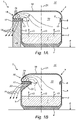
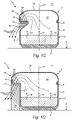
- FIGS 1A-D are schematic cross-sections of cooking assemblies 1 according to embodiments of the present invention.
- Each assembly 1 comprises a cooking pot 2 and a corresponding pot lid 3.
- the cooking pot 2 comprises a flat, horizontal pot bottom 4, and further also a standing pot wall 5.
- the latter pot wall 5 is a mainly cylindrical structure extending in an upward direction of the pot bottom 4, and thereby leading to a pot edge 6.
- the cooking pot 2 defines a container for enclosing food 7, e.g. heating it, in which the pot bottom is placed on a hob of a cooking unit 8 (not shown in the present figures).
- the cooking pot 2 comprises an upwardly directed pot opening, which pot opening is bordered by a pot edge 6.
- the food 7 can be brought into and out of the cooking pot 2 (or, the pot volume 10).
- the pot opening can further be closed off by means of the pot lid 3; thereto, the pot lid 3 comprises a downwardly directed lid edge 9, that is resting onto the pot edge 6.
- the cooking assembly 1 is thereby in a closed configuration.
- a pot volume 10 can be defined, which pot volume 10 extends inside the assembly 1, and is at least partially closed off from an ambient volume 11, which surround volume 11 extends outside the assembly 1.
- said lid edge 8 comprises a downwardly directed lid lip 11, or other structure (e.g. a circumferential fold in the lid edge), for avoiding lateral movement of the pot lid 3 with respect to the cooking pot 2, in the closed configuration of the assembly 1.
- the pot bottom 4 at least partially corresponds to a circular disc, in which the pot wall 5 at least partially relates to a cylindrical sheath, and in which also the pot edge 6 at least partially describes a circle.
- the cooking pot 2 defines an at least partially circular pot opening, of which the radius preferably corresponds to the standardized values, i.e. about 16 cm, about 18 cm, about 20 cm, about 22 cm, about 24 cm, about 26 cm or about 28 cm.
- the invention is in no way limited to such cooking pots 2.
- the assembly 1 is each time in an operative state of the closed configuration; i.e. inside the pot volume 10, a vapour 13 is generated, for example by heating food 7.
- the assembly 1 is thereby also provided with a vapour passage 14, for removing vapour 13 out of the assembly 1.
- Said vapour passage 14 thereby ensures a fluid connection between the pot volume 10 and the ambient volume 11.
- Said vapour passage 14 each time extends in a downward direction, when leaving the pot volume 10. Consequently, the operation of a downdraft extraction system is thereby supported, for example because the vapour 13 is discharged from the pot volume 10 in the direction of a downward vapour discharge 15 (not shown in the present figures).
- the vapour passage 14 extends in the direction of the cooking pot 2, namely in the direction of the pot wall 5. Under the correct circumstances of pressure, temperature and flow rate, the vapour flow will thereby adhere to the surface of the pot wall 5, under the influence of the so-called Coanda-effect. This ensures a further support of the downdraft extraction of vapour 13.
- the assembly 1 further also comprises an overhang 16.
- This overhang 16 comprises an overhang wall 17 , which overhang wall 17 is preferably enclosed by the pot wall 5 and/or by the lid structure 18, depending on the fact if the overhang 16 itself is enclosed by the cooking pot 2, or by the pot lid 3.
- the overhang wall 17 extends between the pot volume 10 and the ambient volume 11, and thereby is part of the separation between both, in the closed configuration of the assembly 1.
- said overhang 16 overhangs a part of the ambient volume 11, which part is indicated as the "overhung ambient volume" 20.
- the overhang wall 17 comprises at least a lying or inclined wall part, above which a part of the pot volume 10 extends, and under which a part of the ambient volume 11 extends; the latter part of the ambient volume 11 is thereby the overhung ambient volume 20.
- Said vapour passage 14 is formed by a number of vapour passage channels 19, extending according to a downward direction through the overhang wall 17. They thereby ensure a downward fluid connection, of the pot volume 10, towards the ambient volume 11 , and through the overhang wall 17 .
- the vapour passage channels 19 thereby extend in the direction of the overhung ambient volume 20, and moreover reach up to that overhung ambient volume 20.
- the vapour passage 14 passes at least through that overhung ambient volume 20.
- FIG. 1A shows an assembly 1 according to the first aspect of the invention, comprising a pot lid 3.
- the overhang 16 is thereby formed by the pot lid 3, in which said collared wall 17 is enclosed by the lid structure 18 .
- Figure 1A further shows the central axis 21 of the assembly 1, that is oriented vertically.
- the shown cooking pot 2 is a traditional, circular cooking pot 2.
- the cooking pot 2 is mainly (thus with the exception of optional additional parts such as a pouring mouth, overpressure valves, handles and similar) described by a solid of revolution, around the central axis 21 .
- the pot lid 3, on the other hand substantially deviates by shapes described by solids of revolution.
- the pot lid 3 comprises an overhang 16, which takes the form of a radially bulging part of the wall structure 18 of the pot lid 3.
- the use of a pot lid 3 according to the present invention thereby allows to use such traditional cooking pots 2 in combination with downdraft extraction systems.
- the operation of these extraction systems is indeed boosted, because vapour 13 is discharged in a downward direction, along the overhang 16.
- the invention is extended in an obvious way to other (traditional) forms of cooking pots 2.
- such bulging/bulge/overhang 16 is provided only along one or more separate, azimuthal sectors of the pot lid.
- the overhang 16 is provided only along one such sector, with an azimuthal aperture angle of at most 120°, preferably at most 90°, preferably between 0° and 90°.
- an azimuthal aperture angle of at most 120°, preferably at most 90°, preferably between 0° and 90°.
- Such a local overhang 16 and corresponding vapour passage 14 can then be directed in a simple way towards the vapour discharge 15 of a downdraft extraction system.
- such an overhang extends over 360°, along the full circumference of the pot lid 3, for cooperation with a downdraft extraction system that is integrated along the edge of hobs.
- the pot lid 3 still mainly takes the form of a solid of revolution, along the central axis 21 .
- a similar alternative can be found in an obvious way, for each of the embodiments of figures 1A-D .
- FIG 1B shows another assembly 1 according to the first aspect of the invention, comprising a pot lid 3.
- the overhang 16 is thereby formed by the pot lid 3 itself, in which said overhung wall 17 is enclosed by the wall structure 18 of the pot lid 3 (i.e. by the lid structure 18).
- the shape of the pot lid 3 substantially deviates for that of a solid of revolution, along the central axis 21 .
- the overhang 16 forms a radially bulging part with respect to the lid edge 9, away from the central axis 21.
- the cooking pot 2 too cannot be identified with such a solid of revolution; indeed, the cooking pot 2 is provided with a radial niche 22, which niche 22 is accessible from the ambient volume 11 of the assembly 1, and extends towards the central axis 21 .
- the niche 22 itself is thereby shaped as a radial deformation of the wall structure of the cooking pot 2, towards the central axis 21 .
- this niche 22 extends over approximately the same azimuthal sector as the overhang 16.
- the niche 22 In an upward direction, the niche 22 extends up to the pot edge 6, in which this pot edge is thus also deformed towards the inside. Moreover, the niche 22 is overhung by said overhang 16, in which the overhung ambient volume 11 extends inside the niche 22. Vapour 13 is discharged in a downward direction through the vapour passage channels 19, and is led along the niche 22, for boosting the downdraft extraction system.
- the specific embodiment according to figure 1C also shows an assembly 1 according to the first aspect of the invention, comprising a cooking pot 2 according to the second aspect of the invention.
- the cooking pot 2 comprises a radial niche 22 that is accessible from the ambient volume 11, and that is deformed by the wall structure 5 of the cooking pot 2 towards the inside.
- this niche 22 is also overhung by means of the same pot wall 5, so that the cooking pot 2 preferably still ends in a (traditionally) circular, oval or otherwise shaped pot edge 6, and is thus appropriate for collaboration with an existing pot lid 3.
- Vapour 13 is discharged in a downward direction through the vapour passage channels 19, and is led along the niche 22, for boosting the downdraft extraction system.
- the overhang i.e. in the broadest sense, the overhanging, radial bulging in the wall structure of the assembly 1
- the overhang is formed together with the cooking pot 2 and the pot lid 3.
- an additional advantage of the embodiments of figures 1B and 1C is that the assembly 1 as a whole does not comprise a locally bulging part, by providing a niche. As a result, it can be stored much more easily, in storing systems such as those provided for traditional cooking utensils.
- the specific embodiment according to figure 1D shows an assembly 1 according to the first aspect of the invention, comprising a cooking pot 2 according to the second aspect of the invention.
- the wall structure 5 of the cooking pot 2 comprises a radial bulging, that overhangs a part of the ambient volume 20, that thereby constitutes an overhang wall 17, and that is provided with downward vapour passage channels 19. In an upward direction, this deformation continues (at least partially) up to the pot edge 6.
- the assembly 1 comprises a specially designed pot lid 3 with a comparable, radial bulging, at the level of the same azimuthal sector, for mutual connection of the cooking pot 2 and the pot lid 3.
- the wall structure 5, 18 of the cooking pot 2 and the pot lid 3 together constitute an overhang 16.
- vapour 13 is discharged in a downward direction along the overhang 16 .
- This design in which the overhang 16 is partially enclosed by the pot lid 3, and partially by the cooking pot 2, allows for an easier cleaning of the bulging pot volume (i.e. the pot volume 10 that is enclosed by the overhang wall 17 ), in an open configuration of the assembly 1.
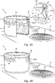
- Figure 2A shows a partially cut-away perspective view of an assembly 1 according to an embodiment of the present invention, comprising a cooking pot 2 and a pot lid 3, arranged on a cooking unit 8 with vapour passage 15.
- a perspective view is shown in figure 2B . Possibly, it relates in both cases to an assembly 1 according to the embodiment of figure 1B , but that is not necessarily the case.
- the pot lid 3 comprises an overhang 16, which that overhangs a niche 22 in the cooking pot 2.
- Vapour 13 can be removed along a vapour passage 14 out of the pot volume 10 towards the vapour discharge 15 .
- this vapour passage 14 leads through vapour passage channels 19 in the overhang 16, up to the overhung ambient volume 20 extending inside the niche 22.
- the assembly 1 is furthermore also provided with handles 23.
- the lid comprises a cover plate 24 (e.g. a concave glass plate). In this way, condensation flows towards the central axis of the assembly, and not necessarily to its circumference. In this way, it can be avoided that too much condensation would go out of the pot volume 10 through the vapour passage channels 19.
- Figure 2A furthermore shows a detail of the vapour passage 14 of the assembly 1.
- the overhang wall 17 is provided with a plurality of vapour passage channels 19, that are arranged in a grid.
- the pot lid 3 is furthermore also provided with a marking 25 along the upper side. This marking 25 indicates where the vapour passage 14 is situated, along the circumference of the assembly 1. In this way, the risk of burning is reduced.
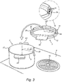
- Figure 3 shows a perspective view of an assembly 1 comprising a cooking pot 2 and a pot lid 3, according to an embodiment of the present invention. For example, it relates to a further embodiment of the embodiment according to figures 2A-B .
- the assembly 1 is now in an open configuration, thus with the pot lid 3 taken from the booking pot 2.
- the cooking pot 2 is thereby positioned on a cooking unit 8 with built-in downdraft extraction system 15.
- the pot lid again comprises an overhang 16, with an overhang wall 17 that is cut by a plurality of vapour passage channels 19 .
- the pot wall 5 forms a niche 22 that extends in an upward direction up to the pot edge 6.
- the niche 22, as well as said overhang 16, describe an azimuthal aperture angle 26 of approximately 50°.
- the niche 22 is configured for being overhung by the overhang.
- the figure shows a detailed view of a plurality of vapour passage channels, enclosed by the pot lid.
- the pot lid 3 can be turned upside down, and be placed, in this way, onto the cooking pot 2.
- the assembly 1 is thereby brought into a closed/operative configuration; this action is indicated by a curved arrow.
- the lid edge 9 now comprises a lid lip 12, that is formed in such way that only a discrete number of mutual positions of the pot lid 3 onto the cooking pot 2 are possible.
- the handles 23', 23" of the cooking pot 2 and the pot lid 3 fit in with each other; only these closed configurations are considered:
- the second, closed-off overhang 30 is positioned diametrically with respect to the first overhang 16.
- Such a design thus provides two or more closed configuration for the assembly 1.
- Figure 4A is a schematic cross-section of a cooking assembly 1 according to a possible embodiment of the present invention, in an operative status of the assembly 1. It relates to an embodiment that is very similar to the embodiment of figure 1B .
- overhang wall 17 is not necessarily extending horizontally/lying, but is inclined towards the central axis 21 . As a result, possible condensation 31 will not accumulate above this overhang wall 17, which would enhance seeping of the condensation 31, through the vapour passage channels 19.
- FIG. 4B A detail is shown in Figure 4B .
- Condensation 31 is led in a downward direction, along the inclined overhang wall 17, up to the cooking pot 2.
- this overhang wall 17 is thereby provided with a profile with ribs and grooves, as shown in the cross-section according to Figure 4C .
- It relates to a detailed view of the vapour passage channels of figures 4A-B , according to a cross-section in a plane that is transverse to the plane of the figures 4A and 4B .
- the condensation 31 is discharged along the grooves.
- the vapour passage channels 19, on the other hand, are provided on ribs, and thereby offer a vapour passage 14.
- FIG 5 is a perspective view of a cooking assembly 1 according to another alternative embodiment.
- the cooking assembly 1 comprises a cooking pot 2 and a pot lid 3.
- a cooking pot 2 mainly as shown in figures 2-3 .
- the cooking pot 2 can or cannot be provided with a pouring mouth 27 (not shown in the figure).
- the cooking assembly 1 comprises a vapour passage 14, formed by a plurality of vapour passage channels 19 that are provided underneath and along a span 32.
- the vapour passage channels 19 preferably extend to underneath the span 32.
- the vapour passage channels 19 preferably extend to a niche 22, enclosed by the assembly 1. With such a design, vapour 13 will be discharged in the niche 22, which stimulates a downdraft and/or sidedraft extraction.
- the niche 22 is preferably spanned by the span 32. With such a design, the rising of vapour 13 from the niche 22 is avoided.
- the span 32 itself is enclosed by a lid edge part 9.
- the vapour passage channels 19 are for example formed by radial grooves that have been made in the lid edge part 9, at the level of the span 32.
- said vapour passage channels 19 extend between an inside and an outside of the lid edge part 9.
- the vapour passage channels 19 extend from the inside.
- the vapour passage channels 19 extend up to the outside, but preferably, this is not the case. Indeed, in case the vapour passage channels 19 do not extend up to the outside, the sideward escape of vapour 13 from the vapour passage channels 19 is avoided.
- the lid edge part 9 is now provided at the bottom side with (interrupted) lid lips 12 with interruption zones in between.
- the lid lips 12 support a stable position of the pot lid 3 onto the cooking pot 2.
- the lid lips 12 thereby have a complementary course with the corresponding pot edge 6.
- the pot lid 2 offers a first, grooved interruption zone. This allows to arrange the span 32 over the niche 22.
- the grooves/vapour passage channels 19 preferably extend between the pot volume 10 and the ambient volume 11, over the pot edge 6.
- the lid edge part 9 still comprises a second, closed span 33. In the shown embodiment, both spans 32, 33 are arranged diametrically with respect to each other.
- the pot lid 3 offers a second, non-grooved (e.g. flat) interruption zone. This allows to arrange the closed span 33 over the niche 22. Thereby, said vapour passage is closed off. Moreover, the user is forced to one of both configurations; in another configuration, a lid lip 12 at the niche 22 hinders each positioning of the pot lid 3 onto the cooking pot 2.
- the vapour passage channels/grooves 19 do not extend beyond the lid lips 12.
- the lid lips 12 are arranged mainly in a circular (or oval) way, appropriate for positioning of the pot lid 3 onto a cooking pot 2 with a mainly circular (or oval) pot edge 6.
- the vapour passage channels/grooves 19 thereby do not extend up beyond to the described circular (or oval) form.
- the pot volume 10 is thereby mainly closed off from the ambient volume 11 .
Landscapes
- Engineering & Computer Science (AREA)
- Food Science & Technology (AREA)
- Health & Medical Sciences (AREA)
- Nutrition Science (AREA)
- Life Sciences & Earth Sciences (AREA)
- Chemical & Material Sciences (AREA)
- Polymers & Plastics (AREA)
- Cookers (AREA)
Claims (9)
- Ensemble 1 comprenant un récipient de cuisson 2 et un couvercle de récipient 3 correspondant, pour fermer le récipient de cuisson 2, dans lequel l'ensemble 1 est doté d'un passage de vapeur 14 pour éliminer la vapeur 13 de l'ensemble 1, dans lequel le passage de vapeur 14 s'étend dans la direction du récipient de cuisson 2, et dans lequel le passage de vapeur 14 est formé par une ou plusieurs voies de passage de vapeur 19, caractérisé en ce que le récipient de cuisson 2 comprend une niche 22, dans lequel les voies de passage de vapeur 19 s'étendent dans ladite niche 22.
- Ensemble 1 selon la revendication 1 précédente, caractérisé en ce que l'ensemble 1 comprend un surplomb 16 ou un enjambement 32, dans lequel les voies de passage de vapeur 19 s'étendent sous le surplomb 16 ou l'enjambement 32.
- Ensemble 1 selon la revendication 2 précédente, caractérisé en ce que la niche 22 est surplombée par ledit surplomb 16, ou est enjambée par ledit enjambement 32.
- Ensemble 1 selon la revendication 3 précédente, caractérisé en ce que le surplomb 16 ou l'enjambement 32 est au moins partiellement compris par le couvercle de récipient 3.
- Ensemble 1 selon la revendication 4 précédente, caractérisé en ce que le surplomb 16 ou l'enjambement 32 est fourni dans le couvercle de récipient 3, et la niche 22 est fournie dans le récipient de cuisson 2, dans lequel le couvercle de récipient 3 comprend un surplomb 30 ou un enjambement 33 fermé supplémentaire.
- Ensemble 1 selon l'une quelconque des revendications 2-5, caractérisé en ce que l'ensemble 1 comprend un enjambement 32, dans lequel les voies de passage de vapeur 19 s'étendent sous et le long de l'enjambement 32, entre un bord de récipient 6 et un bord de couvercle 9.
- Ensemble 1 selon l'une quelconque des revendications 2-5, caractérisé en ce que l'ensemble 1 comprend un surplomb 16, dans lequel les voies de passage de vapeur 19 s'étendent à travers le surplomb 16.
- Récipient de cuisson 2 comprenant un fond de récipient 4 et une paroi de récipient 5, lequel récipient de cuisson 2 est approprié pour être fermé au moyen d'un couvercle de récipient 3, caractérisé en ce que la paroi de récipient 5 comprend une niche 22, appropriée pour être surplombée ou enjambée par un surplomb 16 ou par un enjambement 32.
- Procédé d'extraction de vapeur 13 par aspiration descendante, lors de la préparation d'un aliment 7 au moyen d'un chauffage à l'intérieur d'un ensemble 1, lequel ensemble 1 comprend un récipient de cuisson 2 et un couvercle de récipient 3, et lequel ensemble 1 est ainsi doté d'un passage de vapeur 14, pour éliminer la vapeur 13 de l'ensemble 1, caractérisé en ce que le récipient de cuisson 2 comprend une niche 22, et en ce que le procédé comprend une étape consistant à conduire la vapeur hors de l'ensemble 1, dans lequel la vapeur 13 est conduite dans ou à travers la niche 22.
Applications Claiming Priority (2)
| Application Number | Priority Date | Filing Date | Title |
|---|---|---|---|
| BE2017/5949A BE1025795B1 (nl) | 2017-12-15 | 2017-12-15 | Kooksamenstel, kookpot en potdeksel met dampdoorgang |
| PCT/IB2018/060165 WO2019116355A1 (fr) | 2017-12-15 | 2018-12-17 | Ensemble de cuisson, marmite et couvercle de marmite avec passage de vapeur |
Publications (2)
| Publication Number | Publication Date |
|---|---|
| EP3723562A1 EP3723562A1 (fr) | 2020-10-21 |
| EP3723562B1 true EP3723562B1 (fr) | 2022-04-20 |
Family
ID=60997203
Family Applications (1)
| Application Number | Title | Priority Date | Filing Date |
|---|---|---|---|
| EP18834042.6A Active EP3723562B1 (fr) | 2017-12-15 | 2018-12-17 | Ensemble de cuisson, marmite et couvercle de marmite avec passage de vapeur |
Country Status (4)
| Country | Link |
|---|---|
| US (1) | US11607074B2 (fr) |
| EP (1) | EP3723562B1 (fr) |
| BE (1) | BE1025795B1 (fr) |
| WO (1) | WO2019116355A1 (fr) |
Families Citing this family (2)
| Publication number | Priority date | Publication date | Assignee | Title |
|---|---|---|---|---|
| BE1031320B1 (nl) | 2023-02-03 | 2024-09-16 | Berghoff Worldwide Nv | Potdeksel met dampdoorgang |
| CN120603522A (zh) | 2023-02-03 | 2025-09-05 | 伯格霍夫环球有限公司 | 带蒸汽通道的锅盖 |
Family Cites Families (11)
| Publication number | Priority date | Publication date | Assignee | Title |
|---|---|---|---|---|
| BE463850A (fr) * | ||||
| US1340336A (en) * | 1919-09-16 | 1920-05-18 | Hankulich Michael | Milk-boiler |
| US2184671A (en) * | 1939-05-04 | 1939-12-26 | Joseph J Hollander | Method and means for eliminating odors in cooking |
| FR1056045A (fr) * | 1951-10-29 | 1954-02-23 | Couvercle pour petits récipients | |
| AU515237B2 (en) * | 1978-04-13 | 1981-03-26 | Cenci Giuseppina | Improvement in pot lid (energy saving |
| FR2657002B1 (fr) * | 1990-01-12 | 1995-01-06 | Seb Sa | Recipient de cuisson. |
| US5279279A (en) | 1993-02-26 | 1994-01-18 | Wlcr, Inc. | Deflector device for down-draft cooking range ventilator |
| US6202638B1 (en) | 1998-11-27 | 2001-03-20 | Debbie Didio-Sayer | Grill cover |
| CA2455023A1 (fr) * | 2003-01-09 | 2004-07-09 | Wki Holding Company, Inc. | Recipient de cuisson et couvercle connexe |
| US9492030B2 (en) * | 2009-05-15 | 2016-11-15 | Pellytech Co., Ltd. | Cooking pan provided with exhaust device |
| WO2011009236A1 (fr) * | 2009-07-23 | 2011-01-27 | 江门市盈德钢化玻璃制品有限公司 | Couvercle en verre pourvu dun bord de protection en gel de silice |
-
2017
- 2017-12-15 BE BE2017/5949A patent/BE1025795B1/nl active IP Right Grant
-
2018
- 2018-12-17 WO PCT/IB2018/060165 patent/WO2019116355A1/fr not_active Ceased
- 2018-12-17 US US16/772,324 patent/US11607074B2/en active Active
- 2018-12-17 EP EP18834042.6A patent/EP3723562B1/fr active Active
Also Published As
| Publication number | Publication date |
|---|---|
| BE1025795B1 (nl) | 2019-07-17 |
| US20210068583A1 (en) | 2021-03-11 |
| WO2019116355A1 (fr) | 2019-06-20 |
| EP3723562A1 (fr) | 2020-10-21 |
| BE1025795A1 (nl) | 2019-07-10 |
| US11607074B2 (en) | 2023-03-21 |
Similar Documents
| Publication | Publication Date | Title |
|---|---|---|
| EP2034872B9 (fr) | Appareil permettant de préparer des aliments et organe de guidage d'air pour celui-ci | |
| US7059240B2 (en) | Double heating-type pots | |
| EP3749155A1 (fr) | Couvercle de récipient et ensemble de cuisson doté d'un passage de vapeur | |
| US11607074B2 (en) | Cooking assembly, cooking pot and pot lid with vapour passage | |
| US4532911A (en) | Heat controlling cooker | |
| US10368678B2 (en) | Cooking vessel with or without retainable cover and method of making the same | |
| EP3723563B1 (fr) | Ensemble de cuisson ou rebord de récipient présentant un passage de vapeur | |
| JP4572253B2 (ja) | 調理容器蓋の臭い排出装置 | |
| US20080203095A1 (en) | Vapor-guiding lid for cookware | |
| KR101538588B1 (ko) | 구이용 불판 | |
| US20200337500A1 (en) | Cooking vessel with an opening for drainage | |
| GB2488998A (en) | Sausage cooking apparatus | |
| KR102193754B1 (ko) | 비산방지캡이 구비된 압력밥솥의 스팀배출장치 | |
| WO2024161338A1 (fr) | Couvercle de pot avec passage de vapeur | |
| KR101001613B1 (ko) | 다공성 보조용기를 구비한 조리 용기 | |
| BE1031320B1 (nl) | Potdeksel met dampdoorgang | |
| KR101453838B1 (ko) | 직화구이용 조리용기 | |
| EP3035830A1 (fr) | Dispositif de cuisson | |
| KR101001614B1 (ko) | 수증기를 이용한 조리 용기 | |
| US20070283948A1 (en) | Vertical steamer | |
| DE102012106166A1 (de) | Kochset | |
| CN104739249A (zh) | 智能炊具原料及调料添加装置 |
Legal Events
| Date | Code | Title | Description |
|---|---|---|---|
| STAA | Information on the status of an ep patent application or granted ep patent |
Free format text: STATUS: UNKNOWN |
|
| STAA | Information on the status of an ep patent application or granted ep patent |
Free format text: STATUS: THE INTERNATIONAL PUBLICATION HAS BEEN MADE |
|
| PUAI | Public reference made under article 153(3) epc to a published international application that has entered the european phase |
Free format text: ORIGINAL CODE: 0009012 |
|
| STAA | Information on the status of an ep patent application or granted ep patent |
Free format text: STATUS: REQUEST FOR EXAMINATION WAS MADE |
|
| 17P | Request for examination filed |
Effective date: 20200709 |
|
| AK | Designated contracting states |
Kind code of ref document: A1 Designated state(s): AL AT BE BG CH CY CZ DE DK EE ES FI FR GB GR HR HU IE IS IT LI LT LU LV MC MK MT NL NO PL PT RO RS SE SI SK SM TR |
|
| AX | Request for extension of the european patent |
Extension state: BA ME |
|
| DAV | Request for validation of the european patent (deleted) | ||
| DAX | Request for extension of the european patent (deleted) | ||
| STAA | Information on the status of an ep patent application or granted ep patent |
Free format text: STATUS: EXAMINATION IS IN PROGRESS |
|
| 17Q | First examination report despatched |
Effective date: 20210331 |
|
| GRAP | Despatch of communication of intention to grant a patent |
Free format text: ORIGINAL CODE: EPIDOSNIGR1 |
|
| STAA | Information on the status of an ep patent application or granted ep patent |
Free format text: STATUS: GRANT OF PATENT IS INTENDED |
|
| INTG | Intention to grant announced |
Effective date: 20211102 |
|
| GRAJ | Information related to disapproval of communication of intention to grant by the applicant or resumption of examination proceedings by the epo deleted |
Free format text: ORIGINAL CODE: EPIDOSDIGR1 |
|
| STAA | Information on the status of an ep patent application or granted ep patent |
Free format text: STATUS: EXAMINATION IS IN PROGRESS |
|
| GRAS | Grant fee paid |
Free format text: ORIGINAL CODE: EPIDOSNIGR3 |
|
| STAA | Information on the status of an ep patent application or granted ep patent |
Free format text: STATUS: GRANT OF PATENT IS INTENDED |
|
| GRAP | Despatch of communication of intention to grant a patent |
Free format text: ORIGINAL CODE: EPIDOSNIGR1 |
|
| INTC | Intention to grant announced (deleted) | ||
| GRAA | (expected) grant |
Free format text: ORIGINAL CODE: 0009210 |
|
| STAA | Information on the status of an ep patent application or granted ep patent |
Free format text: STATUS: THE PATENT HAS BEEN GRANTED |
|
| INTG | Intention to grant announced |
Effective date: 20220302 |
|
| AK | Designated contracting states |
Kind code of ref document: B1 Designated state(s): AL AT BE BG CH CY CZ DE DK EE ES FI FR GB GR HR HU IE IS IT LI LT LU LV MC MK MT NL NO PL PT RO RS SE SI SK SM TR |
|
| REG | Reference to a national code |
Ref country code: GB Ref legal event code: FG4D |
|
| REG | Reference to a national code |
Ref country code: CH Ref legal event code: EP |
|
| REG | Reference to a national code |
Ref country code: DE Ref legal event code: R096 Ref document number: 602018034292 Country of ref document: DE |
|
| REG | Reference to a national code |
Ref country code: IE Ref legal event code: FG4D Ref country code: NL Ref legal event code: FP |
|
| REG | Reference to a national code |
Ref country code: AT Ref legal event code: REF Ref document number: 1484500 Country of ref document: AT Kind code of ref document: T Effective date: 20220515 |
|
| REG | Reference to a national code |
Ref country code: LT Ref legal event code: MG9D |
|
| REG | Reference to a national code |
Ref country code: AT Ref legal event code: MK05 Ref document number: 1484500 Country of ref document: AT Kind code of ref document: T Effective date: 20220420 |
|
| PG25 | Lapsed in a contracting state [announced via postgrant information from national office to epo] |
Ref country code: SE Free format text: LAPSE BECAUSE OF FAILURE TO SUBMIT A TRANSLATION OF THE DESCRIPTION OR TO PAY THE FEE WITHIN THE PRESCRIBED TIME-LIMIT Effective date: 20220420 Ref country code: PT Free format text: LAPSE BECAUSE OF FAILURE TO SUBMIT A TRANSLATION OF THE DESCRIPTION OR TO PAY THE FEE WITHIN THE PRESCRIBED TIME-LIMIT Effective date: 20220822 Ref country code: NO Free format text: LAPSE BECAUSE OF FAILURE TO SUBMIT A TRANSLATION OF THE DESCRIPTION OR TO PAY THE FEE WITHIN THE PRESCRIBED TIME-LIMIT Effective date: 20220720 Ref country code: LT Free format text: LAPSE BECAUSE OF FAILURE TO SUBMIT A TRANSLATION OF THE DESCRIPTION OR TO PAY THE FEE WITHIN THE PRESCRIBED TIME-LIMIT Effective date: 20220420 Ref country code: HR Free format text: LAPSE BECAUSE OF FAILURE TO SUBMIT A TRANSLATION OF THE DESCRIPTION OR TO PAY THE FEE WITHIN THE PRESCRIBED TIME-LIMIT Effective date: 20220420 Ref country code: GR Free format text: LAPSE BECAUSE OF FAILURE TO SUBMIT A TRANSLATION OF THE DESCRIPTION OR TO PAY THE FEE WITHIN THE PRESCRIBED TIME-LIMIT Effective date: 20220721 Ref country code: FI Free format text: LAPSE BECAUSE OF FAILURE TO SUBMIT A TRANSLATION OF THE DESCRIPTION OR TO PAY THE FEE WITHIN THE PRESCRIBED TIME-LIMIT Effective date: 20220420 Ref country code: ES Free format text: LAPSE BECAUSE OF FAILURE TO SUBMIT A TRANSLATION OF THE DESCRIPTION OR TO PAY THE FEE WITHIN THE PRESCRIBED TIME-LIMIT Effective date: 20220420 Ref country code: BG Free format text: LAPSE BECAUSE OF FAILURE TO SUBMIT A TRANSLATION OF THE DESCRIPTION OR TO PAY THE FEE WITHIN THE PRESCRIBED TIME-LIMIT Effective date: 20220720 Ref country code: AT Free format text: LAPSE BECAUSE OF FAILURE TO SUBMIT A TRANSLATION OF THE DESCRIPTION OR TO PAY THE FEE WITHIN THE PRESCRIBED TIME-LIMIT Effective date: 20220420 |
|
| PG25 | Lapsed in a contracting state [announced via postgrant information from national office to epo] |
Ref country code: RS Free format text: LAPSE BECAUSE OF FAILURE TO SUBMIT A TRANSLATION OF THE DESCRIPTION OR TO PAY THE FEE WITHIN THE PRESCRIBED TIME-LIMIT Effective date: 20220420 Ref country code: PL Free format text: LAPSE BECAUSE OF FAILURE TO SUBMIT A TRANSLATION OF THE DESCRIPTION OR TO PAY THE FEE WITHIN THE PRESCRIBED TIME-LIMIT Effective date: 20220420 Ref country code: LV Free format text: LAPSE BECAUSE OF FAILURE TO SUBMIT A TRANSLATION OF THE DESCRIPTION OR TO PAY THE FEE WITHIN THE PRESCRIBED TIME-LIMIT Effective date: 20220420 Ref country code: IS Free format text: LAPSE BECAUSE OF FAILURE TO SUBMIT A TRANSLATION OF THE DESCRIPTION OR TO PAY THE FEE WITHIN THE PRESCRIBED TIME-LIMIT Effective date: 20220820 |
|
| REG | Reference to a national code |
Ref country code: DE Ref legal event code: R097 Ref document number: 602018034292 Country of ref document: DE |
|
| PG25 | Lapsed in a contracting state [announced via postgrant information from national office to epo] |
Ref country code: SM Free format text: LAPSE BECAUSE OF FAILURE TO SUBMIT A TRANSLATION OF THE DESCRIPTION OR TO PAY THE FEE WITHIN THE PRESCRIBED TIME-LIMIT Effective date: 20220420 Ref country code: SK Free format text: LAPSE BECAUSE OF FAILURE TO SUBMIT A TRANSLATION OF THE DESCRIPTION OR TO PAY THE FEE WITHIN THE PRESCRIBED TIME-LIMIT Effective date: 20220420 Ref country code: RO Free format text: LAPSE BECAUSE OF FAILURE TO SUBMIT A TRANSLATION OF THE DESCRIPTION OR TO PAY THE FEE WITHIN THE PRESCRIBED TIME-LIMIT Effective date: 20220420 Ref country code: EE Free format text: LAPSE BECAUSE OF FAILURE TO SUBMIT A TRANSLATION OF THE DESCRIPTION OR TO PAY THE FEE WITHIN THE PRESCRIBED TIME-LIMIT Effective date: 20220420 Ref country code: DK Free format text: LAPSE BECAUSE OF FAILURE TO SUBMIT A TRANSLATION OF THE DESCRIPTION OR TO PAY THE FEE WITHIN THE PRESCRIBED TIME-LIMIT Effective date: 20220420 Ref country code: CZ Free format text: LAPSE BECAUSE OF FAILURE TO SUBMIT A TRANSLATION OF THE DESCRIPTION OR TO PAY THE FEE WITHIN THE PRESCRIBED TIME-LIMIT Effective date: 20220420 |
|
| PLBE | No opposition filed within time limit |
Free format text: ORIGINAL CODE: 0009261 |
|
| STAA | Information on the status of an ep patent application or granted ep patent |
Free format text: STATUS: NO OPPOSITION FILED WITHIN TIME LIMIT |
|
| 26N | No opposition filed |
Effective date: 20230123 |
|
| PG25 | Lapsed in a contracting state [announced via postgrant information from national office to epo] |
Ref country code: AL Free format text: LAPSE BECAUSE OF FAILURE TO SUBMIT A TRANSLATION OF THE DESCRIPTION OR TO PAY THE FEE WITHIN THE PRESCRIBED TIME-LIMIT Effective date: 20220420 |
|
| PG25 | Lapsed in a contracting state [announced via postgrant information from national office to epo] |
Ref country code: SI Free format text: LAPSE BECAUSE OF FAILURE TO SUBMIT A TRANSLATION OF THE DESCRIPTION OR TO PAY THE FEE WITHIN THE PRESCRIBED TIME-LIMIT Effective date: 20220420 |
|
| REG | Reference to a national code |
Ref country code: CH Ref legal event code: PL |
|
| PG25 | Lapsed in a contracting state [announced via postgrant information from national office to epo] |
Ref country code: LU Free format text: LAPSE BECAUSE OF NON-PAYMENT OF DUE FEES Effective date: 20221217 |
|
| PG25 | Lapsed in a contracting state [announced via postgrant information from national office to epo] |
Ref country code: LI Free format text: LAPSE BECAUSE OF NON-PAYMENT OF DUE FEES Effective date: 20221231 Ref country code: CH Free format text: LAPSE BECAUSE OF NON-PAYMENT OF DUE FEES Effective date: 20221231 |
|
| PG25 | Lapsed in a contracting state [announced via postgrant information from national office to epo] |
Ref country code: IT Free format text: LAPSE BECAUSE OF FAILURE TO SUBMIT A TRANSLATION OF THE DESCRIPTION OR TO PAY THE FEE WITHIN THE PRESCRIBED TIME-LIMIT Effective date: 20220420 |
|
| PG25 | Lapsed in a contracting state [announced via postgrant information from national office to epo] |
Ref country code: CY Free format text: LAPSE BECAUSE OF FAILURE TO SUBMIT A TRANSLATION OF THE DESCRIPTION OR TO PAY THE FEE WITHIN THE PRESCRIBED TIME-LIMIT Effective date: 20220420 |
|
| PG25 | Lapsed in a contracting state [announced via postgrant information from national office to epo] |
Ref country code: MK Free format text: LAPSE BECAUSE OF FAILURE TO SUBMIT A TRANSLATION OF THE DESCRIPTION OR TO PAY THE FEE WITHIN THE PRESCRIBED TIME-LIMIT Effective date: 20220420 Ref country code: HU Free format text: LAPSE BECAUSE OF FAILURE TO SUBMIT A TRANSLATION OF THE DESCRIPTION OR TO PAY THE FEE WITHIN THE PRESCRIBED TIME-LIMIT; INVALID AB INITIO Effective date: 20181217 |
|
| PG25 | Lapsed in a contracting state [announced via postgrant information from national office to epo] |
Ref country code: MC Free format text: LAPSE BECAUSE OF FAILURE TO SUBMIT A TRANSLATION OF THE DESCRIPTION OR TO PAY THE FEE WITHIN THE PRESCRIBED TIME-LIMIT Effective date: 20220420 |
|
| PG25 | Lapsed in a contracting state [announced via postgrant information from national office to epo] |
Ref country code: TR Free format text: LAPSE BECAUSE OF FAILURE TO SUBMIT A TRANSLATION OF THE DESCRIPTION OR TO PAY THE FEE WITHIN THE PRESCRIBED TIME-LIMIT Effective date: 20220420 Ref country code: MC Free format text: LAPSE BECAUSE OF FAILURE TO SUBMIT A TRANSLATION OF THE DESCRIPTION OR TO PAY THE FEE WITHIN THE PRESCRIBED TIME-LIMIT Effective date: 20220420 |
|
| PG25 | Lapsed in a contracting state [announced via postgrant information from national office to epo] |
Ref country code: MT Free format text: LAPSE BECAUSE OF FAILURE TO SUBMIT A TRANSLATION OF THE DESCRIPTION OR TO PAY THE FEE WITHIN THE PRESCRIBED TIME-LIMIT Effective date: 20220420 |
|
| PG25 | Lapsed in a contracting state [announced via postgrant information from national office to epo] |
Ref country code: BG Free format text: LAPSE BECAUSE OF FAILURE TO SUBMIT A TRANSLATION OF THE DESCRIPTION OR TO PAY THE FEE WITHIN THE PRESCRIBED TIME-LIMIT Effective date: 20220420 |
|
| PG25 | Lapsed in a contracting state [announced via postgrant information from national office to epo] |
Ref country code: BG Free format text: LAPSE BECAUSE OF FAILURE TO SUBMIT A TRANSLATION OF THE DESCRIPTION OR TO PAY THE FEE WITHIN THE PRESCRIBED TIME-LIMIT Effective date: 20220420 |
|
| PGFP | Annual fee paid to national office [announced via postgrant information from national office to epo] |
Ref country code: DE Payment date: 20251211 Year of fee payment: 8 |
|
| PGFP | Annual fee paid to national office [announced via postgrant information from national office to epo] |
Ref country code: GB Payment date: 20251219 Year of fee payment: 8 |
|
| PGFP | Annual fee paid to national office [announced via postgrant information from national office to epo] |
Ref country code: FR Payment date: 20251229 Year of fee payment: 8 Ref country code: NL Payment date: 20251219 Year of fee payment: 8 |
|
| PGFP | Annual fee paid to national office [announced via postgrant information from national office to epo] |
Ref country code: BE Payment date: 20251219 Year of fee payment: 8 |
|
| PGFP | Annual fee paid to national office [announced via postgrant information from national office to epo] |
Ref country code: IE Payment date: 20251219 Year of fee payment: 8 |