EP3723619B1 - Sonde de mesure d'impédance et appareil de biopsie - Google Patents
Sonde de mesure d'impédance et appareil de biopsie Download PDFInfo
- Publication number
- EP3723619B1 EP3723619B1 EP17832127.9A EP17832127A EP3723619B1 EP 3723619 B1 EP3723619 B1 EP 3723619B1 EP 17832127 A EP17832127 A EP 17832127A EP 3723619 B1 EP3723619 B1 EP 3723619B1
- Authority
- EP
- European Patent Office
- Prior art keywords
- conductive wire
- end portion
- distal end
- elongate member
- elongate
- Prior art date
- Legal status (The legal status is an assumption and is not a legal conclusion. Google has not performed a legal analysis and makes no representation as to the accuracy of the status listed.)
- Active
Links
Images


Classifications
-
- A—HUMAN NECESSITIES
- A61—MEDICAL OR VETERINARY SCIENCE; HYGIENE
- A61B—DIAGNOSIS; SURGERY; IDENTIFICATION
- A61B5/00—Measuring for diagnostic purposes; Identification of persons
- A61B5/05—Detecting, measuring or recording for diagnosis by means of electric currents or magnetic fields; Measuring using microwaves or radio waves
- A61B5/053—Measuring electrical impedance or conductance of a portion of the body
- A61B5/0538—Measuring electrical impedance or conductance of a portion of the body invasively, e.g. using a catheter
-
- A—HUMAN NECESSITIES
- A61—MEDICAL OR VETERINARY SCIENCE; HYGIENE
- A61B—DIAGNOSIS; SURGERY; IDENTIFICATION
- A61B10/00—Instruments for taking body samples for diagnostic purposes; Other methods or instruments for diagnosis, e.g. for vaccination diagnosis, sex determination or ovulation-period determination; Throat striking implements
- A61B10/02—Instruments for taking cell samples or for biopsy
- A61B10/0233—Pointed or sharp biopsy instruments
- A61B10/025—Pointed or sharp biopsy instruments for taking bone, bone marrow or cartilage samples
-
- A—HUMAN NECESSITIES
- A61—MEDICAL OR VETERINARY SCIENCE; HYGIENE
- A61B—DIAGNOSIS; SURGERY; IDENTIFICATION
- A61B5/00—Measuring for diagnostic purposes; Identification of persons
- A61B5/68—Arrangements of detecting, measuring or recording means, e.g. sensors, in relation to patient
- A61B5/6846—Arrangements of detecting, measuring or recording means, e.g. sensors, in relation to patient specially adapted to be brought in contact with an internal body part, i.e. invasive
- A61B5/6847—Arrangements of detecting, measuring or recording means, e.g. sensors, in relation to patient specially adapted to be brought in contact with an internal body part, i.e. invasive mounted on an invasive device
- A61B5/6848—Needles
Definitions
- the present invention relates to biopsy devices, and, more particularly, to a biopsy device having a probe for measuring tissue impedance.
- a biopsy may be performed on a patient to help in determining whether the tissue in a region of interest includes cancerous cells.
- One biopsy technique involves inserting a biopsy probe into the tissue region of interest to capture one or more tissue samples from the region. Such a biopsy technique often utilizes a sharp probe to penetrate tissue adjacent to, or in, the tissue region of interest, after which a tissue sample is collected. Efforts continue in the art to improve the ability of the biopsy device to monitor the tissue penetration aspects of collecting a tissue sample.
- US 2016/0081585 A1 discloses a biopsy sampling device having a trocar with sampling opening, an outer needle with four or more electrodes on it, an impedance measuring apparatus coupled to drive current through a first and second electrode, while measuring voltages through a third and fourth electrodes to measure an impedance of tissue adjacent to the electrodes, the inner trocar with the central cavity of the outer needle such that its sharpened tip and sampling opening can protrude from an end of the outer needle and be removed to capture a sample in the sample opening.
- This publication shows a device as defined in the preamble of claim 1.
- the present invention provides a biopsy apparatus having a biopsy probe for measuring tissue impedance to facilitate tissue type determination and/or penetration depth measurements.
- the present invention is directed to the impedance measuring probe for use in a biopsy apparatus according to claim 1.
- the dependent claims refer to preferred embodiments.
- the invention is directed to an impedance measuring probe for use in a biopsy apparatus.
- the impedance measuring probe includes a metal elongate member having a longitudinal axis, an elongate surface, a proximal end, a distal end, a proximal end portion that extends distally from the proximal end, and a distal end portion that extends proximally from the distal end.
- the elongate surface has a recessed longitudinal channel having a radial depth that longitudinally extends from the proximal end portion into the distal end portion.
- the disclosure is directed to a biopsy apparatus.
- the biopsy apparatus includes a biopsy driver having a housing that carries a controller circuit and a motor.
- the controller circuit is electrically and communicatively coupled to the motor.
- the motor has a motor shaft.
- An elongate metal stylet has an elongate surface, a proximal end, a distal end, a proximal end portion that extends distally from the proximal end, and a distal end portion that extends proximally from the distal end.
- the proximal end portion is drivably coupled to the motor shaft of the motor.
- the elongate surface has a plurality of recessed longitudinal channels that extends from the proximal end portion and into the distal end portion.
- Each recessed longitudinal channel of the plurality of recessed longitudinal channels has a radial depth.
- At least one conductive wire electrode is positioned in each channel of the plurality of recessed longitudinal channels, wherein each conductive wire electrode is located in and extends along a respective recessed longitudinal channel of the plurality of recessed longitudinal channels.
- Each conductive wire electrode has a connection end that extends from the proximal end portion of the elongate metal stylet and has a sensing end that is located in the distal end portion of the elongate metal stylet.
- the connection end is electrically connected to the controller circuit.
- Insulation material is disposed in the plurality of recessed longitudinal channels of the elongate metal stylet and around each respective conductive wire electrode so as to electrically insulate each respective conductive wire electrode.
- the sensing end of each respective conductive wire electrode is exposed at the distal end portion of the elongate metal stylet.
- the disclosure in another form not citing all features of claim 1, is directed to an impedance measuring probe arrangement for use with a biopsy apparatus.
- the impedance measuring probe includes a tubular member having a tubular side wall that has a first proximal end, a first distal end, and a first distal end portion that extends proximally from the first distal end.
- the tubular side wall defines a lumen.
- An elongate metal stylet is positioned in the lumen.
- the elongate metal stylet has a second proximal end, a second distal end and a second distal end portion that extends proximally from the second distal end.
- At least one recessed longitudinal channel is formed in one of, or both of, the tubular side wall of the tubular member and the elongate metal stylet, wherein each recessed longitudinal channel extends along a longitudinal extent of one of the tubular side wall of the tubular member and the elongate metal stylet.
- At least one conductive wire electrode is positioned in each recessed longitudinal channel. The conductive wire electrode is electrically insulated from the tubular member and the elongate metal stylet by insulation material. Each conductive wire electrode has a connection end and a sensing end.
- a biopsy apparatus 10 which generally includes a biopsy driver 12 and a probe arrangement 14.
- probe arrangement 14 may include an elongate stylet 16 and an elongate coaxial cannula 18. In some applications, however, elongate stylet 16 may be used without coaxial cannula 18.
- at least one component of probe arrangement 14 e.g., the stylet, the cannula, or both the stylet and the cannula
- biopsy driver 12 has a housing 20 that carries, e.g., contains, a user interface 22, a controller circuit 24, and a motor 26.
- Controller circuit 24 is electrically and communicatively coupled to each of user interface 22 and motor 26, e.g., by wires and/or circuit traces.
- User interface 22 may be, for example, a touch input LCD display screen.
- Motor 26 may be, for example, a direct current (DC) motor having a motor shaft 26-1 that is drivably coupled to elongate stylet 16 to rotate elongate stylet 16.
- Controller circuit 24 is configured to be electrically and communicatively coupled to the impedance measuring probe, e.g., at least one component of probe arrangement 14, as more fully described below.
- controller circuit 24 includes a processor circuit 28, an analog-to-digital (A/D) converter circuit 30, and a pulse width modulation (PWM) circuit 32.
- Processor circuit 28 is electrically and communicatively coupled to A/D converter circuit 30, PWM circuit 32, and user interface 22, e.g., by wires and/or circuit traces.
- Controller circuit 24 may be formed as one or more Application Specific Integrated Circuits (ASIC).
- ASIC Application Specific Integrated Circuits
- A/D converter circuit 30 includes multiple impedance input ports 34, which are grouped into two subsets, namely: impedance input ports ZIN-A, ZIN-B . . . ZIN-X and impedance input ports ZIN-1, ZIN-2 . . . ZIN-N.
- Impedance input ports ZIN-A, ZIN-B . . . ZIN-X may be used, for example, to receive impedance inputs for tissue impedance/composition determinations.
- Impedance input ports ZIN-1, ZIN-2 . . . ZIN-N may be used, for example, to receive impedance inputs for probe penetration depth determinations.
- Respective connection ends from the impedance measuring probe e.g., at least one component of probe arrangement 14 are connected to the impedance input ports, either directly or via a resistive voltage divider arrangement.
- Processor circuit 28 includes, for example, a microprocessor 28-1, a non-transitory electronic memory circuit 28-2, and associated circuitry, such as an input/output interface, clock, buffers, etc.
- Memory circuit 28-2 is a non-transitory electronic memory that may include volatile memory, such as random access memory (RAM), and nonvolatile memory, such as read only memory (ROM), electronically erasable programmable ROM (EEPROM), NOR flash memory, NAND flash memory, etc.
- Processor circuit 28 is configured via software and/or firmware residing in memory circuit 28-2 to execute program instructions to perform functions associated with reading the impedance at each of the multiple impedance input ports 34 of A/D converter circuit 30, and processing the various impedance inputs to generate user data, such as tissue type, to be displayed at user interface 22, and to generate motor control signals, which are supplied to PWM circuit 32.
- PWM circuit 32 converts the motor control signals supplied by processor circuit 28 into PWM signals which are supplied to motor 26 for controlling the revolutions-per-minute (RPMs) of motor shaft 26-1 of motor 26.
- elongate stylet 16 is configured as an impedance measuring probe and coaxial cannula 18 is a passive guide component.
- coaxial cannula 18 includes an elongate tubular member (cannula) 35 and a hub 38.
- the elongate tubular member 35 has a tubular side wall 36, and may be formed from metal, such as stainless steel.
- Hub 38 may be formed from plastic, such as a rigid polymer.
- Tubular side wall 36 has a proximal end 36-1, a distal end 36-2, a proximal end portion 36-3, and a lumen 36-4.
- Proximal end portion 36-3 extends distally from proximal end 36-1.
- Hub 38 is fixedly attached, e.g., by adhesive, to proximal end portion 36-3 of tubular side wall 36.
- Hub 38 may serve as a user handhold and as a mounting feature for attachment to housing 20 of biopsy driver 12.
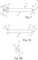
- Lumen 36-4 is sized to slidably receive elongate stylet 16. As shown in Fig. 3 , elongate stylet 16 may be removably positioned in lumen 36-4.
- elongate stylet 16 is a solid elongate member made of metal, e.g., stainless steel, having a longitudinal axis 16-1, a proximal end 16-2, a distal end 16-3, a proximal end portion 16-4 that extends distally from proximal end 16-2, e.g., a distance of one to three centimeters (cm), and a distal end portion 16-5 that extends proximally from distal end 16-3, e.g., a distance of one to five centimeters (cm).
- metal e.g., stainless steel
- Distal end portion 16-5 includes a tapered tip portion 16-6, and distal end 16-3 is a sharp tip of the tapered tip portion 16-6 which is used to create a hole in tissue, e.g., dense tissue, such as bone.
- Elongate stylet 16 also includes an outer elongate surface 40.
- Proximal end portion 16-4 is configured to be drivably coupled to motor shaft 26-1 of motor 26 (see also Figs. 1 and 2 ).
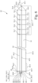
- outer elongate surface 40 has at least one longitudinal channel 42-1, and in the present embodiment, outer elongate surface 40 has a plurality of recessed longitudinal channels 42, individually identified as longitudinal channel 42-1, longitudinal channel 42-2, longitudinal channel 42-3, and longitudinal channel 42-4.
- Each of the plurality of recessed longitudinal channels 42 extends from proximal end portion 16-4 and into distal end portion 16-5, and with each recessed longitudinal channel 42-1, 42-2, 42-3, 42-4 having a radial depth, i.e., a depth in the direction toward longitudinal axis 16-1 that extends along the lengthwise extent of elongate stylet 16.
- the plurality of recessed longitudinal channels 42 may be formed, for example, by cutting the surface, or formed during a casting/molding process.
- a plurality of conductive wire electrodes 44 is located in and extends along the plurality of recessed longitudinal channels 42.
- each recessed longitudinal channel 42-1, 42-2, 42-3, 42-4 receives a respective conductive wire electrode 44-1, 44-2, 44-3, and 44-4.
- one or more of the plurality of recessed longitudinal channels 42 may carry multiple conductive wire electrodes.
- Conductive wire electrode 44-1 has a lengthwise extent between a connection end 46-1 and a sensing end 48-1.
- Conductive wire electrode 44-2 has a lengthwise extent between a connection end 46-2 and a sensing end 48-2.
- Conductive wire electrode 44-3 has a lengthwise extent between a connection end 46-3 and a sensing end 48-3.
- Conductive wire electrode 44-4 has a lengthwise extent between a connection end 46-4 and a sensing end 48-4.
- connection end 46-1, connection end 46-2, connection end 46-3, and connection end 46-4 extends from proximal end portion 16-4 of elongate stylet 16, and each is respectively electrically and communicatively coupled to one of the multiple impedance input ports 34 of A/D converter circuit 30 of controller circuit 24, e.g., one of impedance input ports ZIN-A, ZIN-B . . . ZIN-X and/or impedance input ports ZIN-1, ZIN-2 ... ZIN-N (see also Fig. 2 ).
- sensing end 48-1, sensing end 48-2, sensing end 48-3, and sensing end 48-4 is located at distal end portion 16-5 of elongate stylet 16.
- sensing end 48-1, sensing end 48-2, sensing end 48-3, and sensing end 48-4 are located at distal end portion 16-5 of elongate stylet 16, and are positioned in a circumferential arrangement at the distal end portion 16-5 of elongate stylet 16 near the distal tip at distal end 16-3 of elongate stylet 16, with the circumferential arrangement configured to provide tissue impedance information.
- An insulation material 50 such as a non-conductive polymer, e.g., silicone rubber, is disposed in each recessed longitudinal channel 42-1, 42-2, 42-3, 42-4 and around the respective conductive wire electrode 44-1, 44-2, 44-3, and 44-4 so as to electrically insulate the respective conductive wire electrode 44-1, 44-2, 44-3, and 44-4 from elongate stylet 16, and from coaxial cannula 18 when elongate stylet 16 is inserted into coaxial cannula 18.
- Insulation material 50 encapsulates a lengthwise portion of the conductive wire electrode between the connection end and the sensing end, with the respective ends being free of insulation material to allow electrical contact or connection.
- insulation material 50 fills each recessed longitudinal channel of the plurality of recessed longitudinal channels 42.
- the distal extent of insulation material 50 terminates prior to covering sensing end 48-1, sensing end 48-2, sensing end 48-3, and sensing end 48-4 of the plurality of conductive wire electrodes 44, such that sensing end 48-1, sensing end 48-2, sensing end 48-3, and sensing end 48-4 are exposed at distal end portion 16-5 of elongate stylet 16.
- connection end 46-1, connection end 46-2, connection end 46-3, and connection end 46-4 of the plurality of conductive wire electrodes 44 terminates prior to covering connection end 46-1, connection end 46-2, connection end 46-3, and connection end 46-4 of the plurality of conductive wire electrodes 44, such that connection end 46-1, connection end 46-2, connection end 46-3, and connection end 46-4 are exposed and available for connection to A/D converter circuit 30 of controller circuit 24.
- Fig. 6 shows an alternative elongate stylet 60 configured as an impedance measuring probe, which may be substituted for elongate stylet 16 of probe arrangement 14.
- Elongate stylet 60 may be in the form of a solid elongate member made from metal, e.g., stainless steel, having a longitudinal axis 60-1, a proximal end 60-2, a distal end 60-3, a proximal end portion 60-4 that extends distally from proximal end 60-2, e.g., a distance of one to three centimeters (cm), and a distal end portion 60-5 that extends proximally from distal end 60-3, e.g., a distance of one to five centimeters (cm).
- metal e.g., stainless steel
- Elongate stylet 60 also includes an outer elongate surface 62.
- Proximal end portion 16-4 is configured to be drivably coupled to motor shaft 26-1 of motor 26 (see also Figs. 1 and 2 ).
- Distal end portion 60-5 includes a tapered tip portion 60-6, and distal end 16-3 is a sharp tip of the tapered tip portion 60-6 which is used to create a hole in tissue, e.g., dense tissue, such as bone.
- a plurality of conductive wire electrodes 94 is located in and extends along the plurality of recessed longitudinal channels 92.
- each recessed longitudinal channel 92-1, 92-2, 92-3, 92-4 receives a respective conductive wire electrode 94-1, 94-2, 94-3, and 94-4.
- one or more of the plurality of recessed longitudinal channels 92 may carry multiple conductive wire electrodes.
- Conductive wire electrode 94-1 has a lengthwise extent between a connection end 96-1 and a sensing end 98-1.
- Conductive wire electrode 94-2 has a lengthwise extent between a connection end 96-2 and a sensing end 98-2.
- Conductive wire electrode 94-3 has a lengthwise extent between a connection end 96-3 and a sensing end 98-3.
- Conductive wire electrode 94-4 has a lengthwise extent between a connection end 96-4 and a sensing end 98-4.
- connection end 96-1, connection end 96-2, connection end 96-3, and connection end 96-4 extends from proximal end portion 86-3 of tubular side wall 86, and each is respectively electrically and communicatively coupled to one of the multiple impedance input ports 34 of A/D converter circuit 30 of controller circuit 24, e.g., one of impedance input ports ZIN-A, ZIN-B . . . ZIN-X and/or impedance input ports ZIN-1, ZIN-2 ... ZIN-N.
- sensing end 98-1, sensing end 98-2, sensing end 98-3, and sensing end 98-4 is located at distal end portion 86-5 of coaxial cannula 80.
- insulation material 50 fills each recessed longitudinal channel of the plurality of recessed longitudinal channels 92.
- the distal extent of insulation material 50 terminates prior to covering sensing end 98-1, sensing end 98-2, sensing end 98-3, and sensing end 98-4 of the plurality of conductive wire electrodes 94, such that sensing end 98-1, sensing end 98-2, sensing end 98-3, and sensing end 98-4 are exposed at distal end portion 86-5 of coaxial cannula 80.
- connection end 96-1, connection end 96-2, connection end 96-3, and connection end 96-4 of the plurality of conductive wire electrodes 94 terminates prior to covering connection end 96-1, connection end 96-2, connection end 96-3, and connection end 96-4 of the plurality of conductive wire electrodes 94, such that connection end 96-1, connection end 96-2, connection end 96-3, and connection end 96-4 are exposed and available for connection to A/D converter circuit 30 of controller circuit 24 (see also Fig. 2 ).
- Fig. 8 shows an alternative recessed channel arrangement in tubular member 84 of coaxial cannula 80, wherein elongate interior surface 88 has the plurality of recessed longitudinal channels 92, and wherein each recessed longitudinal channel 92-1, 92-2, 92-3, 92-4 receives the respective conductive wire electrode 94-1, 94-2, 94-3, and 94-4.
- insulation material 50 such as a non-conductive polymer, e.g., silicone rubber, is disposed in each recessed longitudinal channel 92-1, 92-2, 92-3, 92-4 and around the respective conductive wire electrode 94-1, 94-2, 94-3, and 94-4 so as to electrically insulate the respective conductive wire electrode 94-1, 94-2, 94-3, and 94-4 from tubular member 84 of coaxial cannula 80, and from any elongate stylet (e.g., elongate stylet 16 or elongate stylet 60) that is inserted into coaxial cannula 80.
- elongate stylet e.g., elongate stylet 16 or elongate stylet 60
- each of the elongate interior surface 88 and the elongate exterior surface 90 of tubular member 84 may have one or more of the plurality of recessed longitudinal channels 92 and one or more of the plurality of conductive wire electrodes 94.
- each of elongate stylet 16 and elongate stylet 60 may be formed from a tubular member, such as tubular member 84 having any of the arrangements of the plurality of recessed longitudinal channels 92 described above for receiving one or more conductive wire electrodes.
- impedance may be measured between any two electrode sensing ends of two corresponding conductive wire electrodes, or alternatively, between a sensing end of a conductive wire electrode and a metal conductor serving as an electrical common electrical path, such as the metal elongate member, e.g., one of the elongate stylet or the tubular member of the coaxial cannula, or an electrode sensing end of a conductive wire electrode predefined to serve as a common electrical path, e.g., sensing end 70-1.
- the metal elongate member e.g., one of the elongate stylet or the tubular member of the coaxial cannula
- an electrode sensing end of a conductive wire electrode predefined to serve as a common electrical path e.g., sensing end 70-1.
- insulation material may be applied to, or formed on, the respective conductive wire electrode prior to insertion into a respective recessed longitudinal channel of the impedance measuring probe.
- near is a relative modifier intended to indicate permissible variation from the characteristic so modified. To the extent that a specific interpretation is required, for purposes of the present invention, “near” may mean less than 1.5 cm from the referenced structure.
- the impedance measuring probe for use in a biopsy apparatus.
- the impedance measuring probe includes an elongate member, e.g., metal, having a longitudinal axis, an elongate surface, a proximal end, a distal end, a proximal end portion that extends distally from the proximal end, and a distal end portion that extends proximally from the distal end.
- the elongate surface has a recessed longitudinal channel having a radial depth that longitudinally extends from the proximal end portion into the distal end portion.
- a conductive wire electrode having a connection end and a sensing end, is located in and extends along the recessed longitudinal channel.
- connection end extends from the proximal end portion of the elongate member and the sensing end is located at the distal end portion of the elongate member.
- An insulation material is disposed in the recessed longitudinal channel of the elongate member and around the conductive wire electrode so as to electrically insulate the conductive wire electrode.
- the sensing end of the conductive wire electrode is exposed at the distal end portion of the elongate member.
- the impedance measuring probe may be configured to measure the impedance at the sensing end of the conductive wire.
- the elongate member may be a solid metal stylet having an outer surface, wherein the outer surface of the stylet is the elongate surface having the recessed longitudinal channel.
- the elongate member may be a tubular member having a tubular side wall that defines a lumen, an exterior surface, and an interior surface, wherein the exterior surface is the elongate surface having the recessed longitudinal channel.
- the elongate member may be a tubular member having a tubular side wall that defines a lumen and an interior surface, wherein the interior surface is the elongate surface having the recessed longitudinal channel.
- the insulation material may fill the recessed longitudinal channel.
- a plurality of conductive wire electrodes may be located in and extends along the recessed longitudinal channel, wherein the insulation material electrically insulates the plurality of conductive wire electrodes from one another and from the metal elongate member.
- Each conductive wire electrode of the plurality of conductive wire electrodes has a connection end and a sensing end, with the connection end extending from the proximal end portion of the metal elongate member and the sensing end being located at the distal end portion of the metal elongate member.
- the elongate member has a plurality of recessed longitudinal channels that extend from the proximal end portion and into the distal end portion.
- Each conductive wire electrode of a plurality of conductive wire electrodes may be located in and extends along a respective recessed longitudinal channel of the plurality of recessed longitudinal channels, with each conductive wire electrode of the plurality of conductive wire electrodes having a connection end extending from the proximal end portion of the metal elongate member and a sensing end located in the distal end portion of the elongate member.
- Insulation material is disposed in the plurality of recessed longitudinal channels of the elongate member and around a respective conductive wire electrode of the plurality of conductive wire electrodes so as to electrically insulate the respective conductive wire electrode.
- the sensing end of each respective conductive wire electrode of the plurality of conductive wire electrodes is exposed at the distal end portion of the elongate member.
- a circumferential arrangement of multiple sensing ends may be located at the distal end portion of the elongate member near a distal tip of the elongate member.
- the circumferential arrangement of the multiple sensing ends may be configured to provide tissue impedance information.
- a longitudinally spaced arrangement of multiple sensing ends may be located along the distal end portion of the elongate member.
- the longitudinally spaced arrangement of multiple sensing ends may be configured to provide penetration depth information.
- a longitudinally spaced arrangement of multiple circumferential metallic bands may surround the distal end portion of the metal elongate member, with insulation material interposed between the multiple circumferential metallic bands and the metal elongate member.
- the multiple circumferential metallic bands may be respectively electrically connected to the longitudinally spaced arrangement of multiple sensing ends.
- the elongate member may be one of a solid stylet and a tubular member having a tubular side wall.
- four conductive wire electrodes may be provided and/or the conductive wire electrodes may equidistantly be spaced along the circumference, optionally with an angle of 90° relative to each other.
- the biopsy apparatus includes a biopsy driver having a housing that carries a controller circuit and a motor.
- the controller circuit is electrically and communicatively coupled to the motor.
- the motor has a motor shaft.
- An elongate stylet i.e. metal, has an elongate surface, a proximal end, a distal end, a proximal end portion that extends distally from the proximal end, and a distal end portion that extends proximally from the distal end.
- the proximal end portion is drivably coupled to the motor shaft of the motor.
- the elongate surface has a plurality of recessed longitudinal channels that extends from the proximal end portion and into the distal end portion.
- Each recessed longitudinal channel of the plurality of recessed longitudinal channels has a radial depth.
- At least one conductive wire electrode is positioned in each channel of the plurality of recessed longitudinal channels, wherein each conductive wire electrode is located in and extends along a respective recessed longitudinal channel of the plurality of recessed longitudinal channels.
- Each conductive wire electrode has a connection end that extends from the proximal end portion of the elongate stylet and has a sensing end that is located in the distal end portion of the elongate stylet. The connection end is electrically connected to the controller circuit. Insulation material is disposed in the plurality of recessed longitudinal channels of the elongate stylet and around each respective conductive wire electrode so as to electrically insulate each respective conductive wire electrode.
- a circumferential arrangement of multiple sensing ends may located at the distal end portion of the elongate metal stylet near the distal tip.
- the circumferential arrangement of the multiple sensing ends may be configured to provide tissue impedance information to the controller circuit.
- a longitudinally spaced arrangement of multiple sensing ends may be located along the distal end portion of the elongate metal stylet.
- the longitudinally spaced arrangement of multiple sensing ends may be configured to provide penetration depth information to the controller circuit.
- a longitudinally spaced arrangement of multiple circumferential metallic bands may surround the distal end portion of the elongate metal stylet, with insulation material interposed between the multiple circumferential metallic bands and the elongate metal stylet.
- the multiple circumferential metallic bands may be respectively electrically connected to the longitudinally spaced arrangement of multiple sensing ends.
- the biopsy apparatus may further include a coaxial cannula having a hub and a tubular member, the tubular member having a tubular side wall having a proximal end, a distal end, and a distal end portion that extends proximally from the distal end, and the side wall defining a lumen.
- the elongate metal stylet may be positioned in the lumen.
- the tubular member may have at least one recessed longitudinal channel formed in the tubular side wall that extends along a longitudinal extent of the tubular side wall of the tubular member.
- At least one additional conductive wire electrode may be positioned in each recessed longitudinal channel of the tubular member, and each additional conductive wire electrode may be electrically insulated from the tubular member by insulation material, and each additional conductive wire electrode has a connection end electrically connected to the controller circuit and an exposed sensing end.
- the impedance measuring probe for use with a biopsy apparatus.
- the impedance measuring probe includes a tubular member having a tubular side wall that has a first proximal end, a first distal end, and a first distal end portion that extends proximally from the first distal end.
- the tubular side wall defines a lumen.
- An elongate stylet i.e. metal, is positioned in the lumen.
- the elongate stylet has a second proximal end, a second distal end and a second distal end portion that extends proximally from the second distal end.
- At least one recessed longitudinal channel is formed in one of, or both of, the tubular side wall of the tubular member and the elongate stylet, wherein each recessed longitudinal channel extends along a longitudinal extent of one of the tubular side wall of the tubular member and the elongate stylet.
- At least one conductive wire electrode is positioned in each recessed longitudinal channel. The conductive wire electrode is electrically insulated from the tubular member and the elongate stylet by insulation material. Each conductive wire electrode has a connection end and a sensing end. The impedance measuring probe may be configured to measure the impedance at the sensing end of the conductive wire.
- the tubular side wall may define an exterior surface and an interior surface, wherein a respective recessed longitudinal channel may be located on at least one of the exterior surface and the interior surface.
- the tubular side wall of the tubular member may have a plurality of recessed longitudinal channels and a plurality of conductive wire electrodes.
- Each recessed longitudinal channel of the plurality of recessed longitudinal channels has positioned therein at least one conductive wire electrode of the plurality of conductive wire electrodes, with each conductive wire electrode of the plurality of conductive wire electrodes having a connection end extending from the first proximal end portion of the tubular side wall configured for connection to a controller circuit of the biopsy apparatus and having a sensing end located in the first distal end portion of the tubular side wall.
- Insulation material is disposed in the plurality of recessed longitudinal channels of the tubular side wall and around each respective conductive wire electrode of the plurality of conductive wire electrodes so as to electrically insulate each respective conductive wire electrode, and wherein the sensing end of each respective conductive wire electrode of the plurality of conductive wire electrodes is exposed at the first distal end portion of the tubular side wall.
- a circumferential arrangement of multiple sensing ends may be located at the first distal end portion of the tubular side wall.
- the circumferential arrangement of the multiple sensing ends may be configured to provide tissue impedance information to the controller circuit.
- the elongate metal stylet may have a plurality of recessed longitudinal channels, and a plurality of conductive wire electrodes.
- Each recessed longitudinal channel of the plurality of recessed longitudinal channels has positioned therein at least one conductive wire electrode of the plurality of conductive wire electrodes, with each conductive wire electrode of the plurality of conductive wire electrodes having a connection end extending from the second proximal end portion of the elongate metal stylet configured for connection to a controller circuit of the biopsy apparatus and having a sensing end located in the second distal end portion of the elongate metal stylet.
- Insulation material is disposed in the plurality of recessed longitudinal channels of the tubular side wall and around each respective conductive wire electrode of the plurality of conductive wire electrodes so as to electrically insulate each respective conductive wire electrode, and wherein the sensing end of each respective conductive wire electrode of the plurality of conductive wire electrodes is exposed at the second distal end portion of the elongate metal stylet.
- a circumferential arrangement of multiple sensing ends may be located at the second distal end portion of the elongate metal stylet.
- the circumferential arrangement of the multiple sensing ends may be configured to provide tissue impedance information to the controller circuit.
- a longitudinally spaced arrangement of multiple sensing ends may be located along the second distal end portion of the metal elongate member.
- the longitudinally spaced arrangement of multiple sensing ends may be configured to provide penetration depth information to the controller circuit.
- four conductive wire electrodes may be provided and/or the conductive wire electrodes may equidistantly be spaced along the circumference, optionally with an angle of 90° relative to each other.
Landscapes
- Health & Medical Sciences (AREA)
- Life Sciences & Earth Sciences (AREA)
- General Health & Medical Sciences (AREA)
- Public Health (AREA)
- Biomedical Technology (AREA)
- Heart & Thoracic Surgery (AREA)
- Medical Informatics (AREA)
- Molecular Biology (AREA)
- Surgery (AREA)
- Animal Behavior & Ethology (AREA)
- Pathology (AREA)
- Engineering & Computer Science (AREA)
- Veterinary Medicine (AREA)
- Physics & Mathematics (AREA)
- Biophysics (AREA)
- Nuclear Medicine, Radiotherapy & Molecular Imaging (AREA)
- Radiology & Medical Imaging (AREA)
- Hematology (AREA)
- Immunology (AREA)
- Orthopedic Medicine & Surgery (AREA)
- Rheumatology (AREA)
- Measurement And Recording Of Electrical Phenomena And Electrical Characteristics Of The Living Body (AREA)
Claims (11)
- Sonde de mesure d'impédance pour une utilisation dans un appareil de biopsie (10), comprenant :
un élément allongé en métal (16) présentant un axe longitudinal (16-1), une surface allongée (40), une extrémité proximale (16-2), une extrémité distale (16-3), une partie d'extrémité proximale (16-4) qui s'étend distalement à partir de l'extrémité proximale (16-2), et une partie d'extrémité distale (16-5) qui s'étend proximalement à partir de l'extrémité distale (16-3), la sonde de mesure d'impédance étant caractérisée par :la surface allongée (40), qui présente un canal longitudinal évidé (42-1) présentant une épaisseur radiale qui s'étend longitudinalement à partir de la partie d'extrémité proximale (16-4) dans la partie d'extrémité distale (16-5) ;une pluralité d'électrodes à fil conducteur (44), chaque électrode à fil conducteur de la pluralité d'électrodes à fil conducteur présentant une extrémité de connexion (46-2) et une extrémité de détection (48-2), chaque électrode à fil conducteur (44) de la pluralité d'électrodes à fil conducteur étant située dans et s'étendant le long du canal longitudinal évidé (42-1), l'extrémité de connexion (46-2) s'étendant à partir de la partie d'extrémité proximale (16-4) de l'élément allongé en métal (16) et l'extrémité de détection (48-2) étant située au niveau de la partie d'extrémité distale (16-5) de l'élément allongé en métal (16) ; etun matériau isolant (50) disposé dans le canal longitudinal évidé (42-1) de l'élément allongé en métal (16) et autour des électrodes à fil conducteur (44) de manière à isoler électriquement les électrodes à fil conducteur (44), et l'extrémité de détection (48-2) de l'électrode à fil conducteur (44) étant exposée au niveau de la partie d'extrémité distale (16-5) de l'élément allongé en métal (16). - Sonde de mesure d'impédance selon la revendication 1, dans laquelle l'élément allongé en métal (16) est un stylet en métal solide présentant une surface externe, dans laquelle la surface externe du stylet est la surface allongée (40) présentant le canal longitudinal évidé (42-1).
- Sonde de mesure d'impédance selon la revendication 1, dans laquelle l'élément allongé en métal (16) est un élément tubulaire présentant une paroi latérale tubulaire (86) qui définit une lumière (86-4), une surface extérieure (90), et une surface intérieure (88), dans laquelle la surface extérieure (90) est la surface allongée (40) présentant le canal longitudinal évidé (42-1).
- Sonde de mesure d'impédance selon la revendication 1, dans laquelle l'élément allongé en métal (16) est un élément tubulaire présentant une paroi latérale tubulaire (86) qui définit une lumière (86-4) et une surface intérieure (88), dans laquelle la surface intérieure (88) est la surface allongée (44) présentant le canal longitudinal évidé (42-1).
- Sonde de mesure d'impédance selon l'une quelconque des revendications 1 à 4, dans laquelle le matériau isolant (50) remplit le canal longitudinal évidé (42-1).
- Sonde de mesure d'impédance selon l'une quelconque des revendications 1 à 5, dans laquelle le matériau isolant (50) isole électriquement la pluralité d'électrodes à fil conducteur (44) les unes des autres et à partir de l'élément allongé en métal (16).
- Sonde de mesure d'impédance selon l'une quelconque des revendications 1 à 6, dans laquelle l'élément allongé en métal (16) présente une pluralité de canaux longitudinaux évidés (42-1) qui s'étendent à partir de la partie d'extrémité proximale (16-4) et dans la partie d'extrémité distale (16-5), etdans laquelle chaque électrode à fil conducteur de la pluralité d'électrodes à fil conducteur est située dans et s'étend le long d'un canal longitudinal évidé (42-1) respectif de la pluralité de canaux longitudinaux évidés (16) ; etun matériau isolant (50) est disposé dans la pluralité de canaux longitudinaux évidés (42-1) de l'élément allongé en métal (16) et autour d'une électrode à fil conducteur (44) respective de la pluralité d'électrodes à fil conducteur de manière à isoler électriquement l'électrode à fil conducteur respective.
- Sonde de mesure d'impédance selon l'une quelconque des revendications 1 à 7, comprenant un agencement circonférentiel de multiples extrémités de détection (48-2) situées au niveau de la partie d'extrémité distale (16-5) de l'élément allongé en métal à proximité d'une pointe distale de l'élément allongé en métal (16), l'agencement circonférentiel des multiples extrémités de détection (48-2) étant configuré pour fournir des informations d'impédance de tissu.
- Sonde de mesure d'impédance selon l'une quelconque des revendications 7 et 8, comprenant un agencement longitudinalement espacé de multiples extrémités de détection (48-2) situées le long de la partie d'extrémité distale (16-5) de l'élément allongé en métal, l'agencement longitudinalement espacé des multiples extrémités de détection (48-2) étant configuré pour fournir des informations de profondeur de pénétration.
- Sonde de mesure d'impédance selon la revendication 9, comprenant un agencement longitudinalement espacé de multiples bandes métalliques circonférentielles (72) qui entourent la partie d'extrémité distale (16-5) de l'élément allongé en métal (16), un matériau isolant (50) étant intercalé entre les multiples bandes métalliques circonférentielles (72) et l'élément allongé en métal (16), les multiples bandes métalliques circonférentielles (72) étant respectivement connectées électriquement à l'agencement longitudinalement espacé des multiples extrémités de détection (48-2).
- Sonde de mesure d'impédance selon l'une quelconque des revendications 1 à 10, dans laquelle l'élément allongé en métal (16) est un d'un stylet solide (16) et d'un élément tubulaire (35) présentant une paroi latérale tubulaire (36).
Applications Claiming Priority (1)
| Application Number | Priority Date | Filing Date | Title |
|---|---|---|---|
| PCT/US2017/066660 WO2019117943A1 (fr) | 2017-12-15 | 2017-12-15 | Sonde de mesure d'impédance et appareil de biopsie |
Publications (3)
| Publication Number | Publication Date |
|---|---|
| EP3723619A1 EP3723619A1 (fr) | 2020-10-21 |
| EP3723619B1 true EP3723619B1 (fr) | 2025-04-16 |
| EP3723619C0 EP3723619C0 (fr) | 2025-04-16 |
Family
ID=61003371
Family Applications (1)
| Application Number | Title | Priority Date | Filing Date |
|---|---|---|---|
| EP17832127.9A Active EP3723619B1 (fr) | 2017-12-15 | 2017-12-15 | Sonde de mesure d'impédance et appareil de biopsie |
Country Status (5)
| Country | Link |
|---|---|
| US (1) | US12144601B2 (fr) |
| EP (1) | EP3723619B1 (fr) |
| JP (1) | JP7048743B2 (fr) |
| CN (1) | CN111491568B (fr) |
| WO (1) | WO2019117943A1 (fr) |
Families Citing this family (8)
| Publication number | Priority date | Publication date | Assignee | Title |
|---|---|---|---|---|
| US7818053B2 (en) | 2003-02-21 | 2010-10-19 | Dtherapeutics, Llc | Devices, systems and methods for plaque type determination |
| US11759268B2 (en) | 2012-04-05 | 2023-09-19 | C. R. Bard, Inc. | Apparatus and methods relating to intravascular positioning of distal end of catheter |
| US10159531B2 (en) | 2012-04-05 | 2018-12-25 | C. R. Bard, Inc. | Apparatus and methods relating to intravascular positioning of distal end of catheter |
| JP7386334B2 (ja) | 2019-09-20 | 2023-11-24 | バード・ペリフェラル・バスキュラー・インコーポレーテッド | 組織試料インピーダンス測定を有する生検システム |
| US11045653B1 (en) * | 2021-02-11 | 2021-06-29 | Eagle Point Medical LLC | Multi-electrode leads, adapters, and methods for left bundle branch pacing with depth control |
| US20220401702A1 (en) * | 2021-06-18 | 2022-12-22 | Bard Access Systems, Inc. | Impedance-Determining Medical Systems |
| US12203960B2 (en) * | 2021-12-28 | 2025-01-21 | Industrial Technology Research Institute | Manufacturing fixture and process for electrode of neuromodulation probe |
| CN117679634B (zh) * | 2024-01-31 | 2024-05-03 | 苏州新云医疗设备有限公司 | 植入电极及电刺激系统 |
Family Cites Families (53)
| Publication number | Priority date | Publication date | Assignee | Title |
|---|---|---|---|---|
| US5449370A (en) | 1993-05-12 | 1995-09-12 | Ethicon, Inc. | Blunt tipped ultrasonic trocar |
| US6033399A (en) | 1997-04-09 | 2000-03-07 | Valleylab, Inc. | Electrosurgical generator with adaptive power control |
| US6103033A (en) | 1998-03-04 | 2000-08-15 | Therasense, Inc. | Process for producing an electrochemical biosensor |
| US6391005B1 (en) * | 1998-03-30 | 2002-05-21 | Agilent Technologies, Inc. | Apparatus and method for penetration with shaft having a sensor for sensing penetration depth |
| WO2000044286A1 (fr) | 1999-01-28 | 2000-08-03 | Minrad Inc. | Dispositif d'echantillonnage et procede d'extraction d'un echantillon |
| US6402701B1 (en) * | 1999-03-23 | 2002-06-11 | Fna Concepts, Llc | Biopsy needle instrument |
| US6692445B2 (en) * | 1999-07-27 | 2004-02-17 | Scimed Life Systems, Inc. | Biopsy sampler |
| US6770070B1 (en) | 2000-03-17 | 2004-08-03 | Rita Medical Systems, Inc. | Lung treatment apparatus and method |
| US6913579B2 (en) | 2001-05-01 | 2005-07-05 | Surgrx, Inc. | Electrosurgical working end and method for obtaining tissue samples for biopsy |
| US6560472B2 (en) | 2001-06-21 | 2003-05-06 | Microhelix, Inc. | Multi-channel structurally robust brain probe and method of making the same |
| US7160258B2 (en) * | 2001-06-26 | 2007-01-09 | Entrack, Inc. | Capsule and method for treating or diagnosing the intestinal tract |
| US7010356B2 (en) | 2001-10-31 | 2006-03-07 | London Health Sciences Centre Research Inc. | Multichannel electrode and methods of using same |
| AU2002357166A1 (en) * | 2001-12-12 | 2003-06-23 | Tissuelink Medical, Inc. | Fluid-assisted medical devices, systems and methods |
| US9072543B2 (en) | 2002-05-31 | 2015-07-07 | Vidacare LLC | Vascular access kits and methods |
| WO2008033871A2 (fr) | 2006-09-12 | 2008-03-20 | Vidacare Corporation | Appareil et procédé de biopsie et d'aspiration de moelle osseuse |
| IL165224A0 (en) | 2002-05-31 | 2005-12-18 | Vidacare Corp | Apparatus and method to access bone marrow |
| US9451968B2 (en) | 2002-05-31 | 2016-09-27 | Vidacare LLC | Powered drivers, intraosseous devices and methods to access bone marrow |
| US8668698B2 (en) | 2002-05-31 | 2014-03-11 | Vidacare Corporation | Assembly for coupling powered driver with intraosseous device |
| US20070049945A1 (en) | 2002-05-31 | 2007-03-01 | Miller Larry J | Apparatus and methods to install, support and/or monitor performance of intraosseous devices |
| US9314228B2 (en) | 2002-05-31 | 2016-04-19 | Vidacare LLC | Apparatus and method for accessing the bone marrow |
| US9504477B2 (en) | 2003-05-30 | 2016-11-29 | Vidacare LLC | Powered driver |
| US8414580B2 (en) | 2004-04-20 | 2013-04-09 | Boston Scientific Scimed, Inc. | Co-access bipolar ablation probe |
| US20060079774A1 (en) | 2004-10-08 | 2006-04-13 | Wendell Anderson | Microwave biopsy probe |
| US20090204021A1 (en) | 2004-12-16 | 2009-08-13 | Senorx, Inc. | Apparatus and method for accessing a body site |
| US8512333B2 (en) * | 2005-07-01 | 2013-08-20 | Halt Medical Inc. | Anchored RF ablation device for the destruction of tissue masses |
| JP4955681B2 (ja) * | 2005-08-10 | 2012-06-20 | シー・アール・バード・インコーポレーテッド | 直線駆動装置を有する単一挿入複数サンプリング生検デバイス |
| US8944069B2 (en) | 2006-09-12 | 2015-02-03 | Vidacare Corporation | Assemblies for coupling intraosseous (IO) devices to powered drivers |
| CA2689485C (fr) | 2007-06-04 | 2014-09-23 | Ao Technology Ag | Canule |
| US10219832B2 (en) | 2007-06-29 | 2019-03-05 | Actuated Medical, Inc. | Device and method for less forceful tissue puncture |
| US8328738B2 (en) | 2007-06-29 | 2012-12-11 | Actuated Medical, Inc. | Medical tool for reduced penetration force with feedback means |
| FI20075978A0 (fi) * | 2007-12-31 | 2007-12-31 | Katja Paassilta | Järjestely ja menetelmä |
| CA2639116C (fr) | 2008-08-25 | 2013-06-18 | Walter Meier (Climate Canada) Ltd. | Couvercle isolant pour tubes a decharge a vapeur |
| WO2010107424A1 (fr) * | 2009-03-16 | 2010-09-23 | C.R. Bard, Inc. | Dispositif de biopsie comprenant une coupe rotative |
| WO2010148083A2 (fr) * | 2009-06-16 | 2010-12-23 | Surgivision, Inc. | Dispositifs guidés par irm et systèmes d'intervention guidés par irm qui peuvent suivre et générer des visualisations dynamiques des dispositifs presque en temps réel |
| US9498192B2 (en) | 2009-08-03 | 2016-11-22 | Dune Medical Devices Ltd. | Surgical tool |
| US10448872B2 (en) * | 2010-03-16 | 2019-10-22 | Medtronic Minimed, Inc. | Analyte sensor apparatuses having improved electrode configurations and methods for making and using them |
| US8894654B2 (en) | 2010-03-31 | 2014-11-25 | Smart Medical Devices, Inc. | Depth controllable and measurable medical driver devices and methods of use |
| JP5927176B2 (ja) | 2010-04-01 | 2016-06-01 | エコーレ ポリテクニーク フェデラーレ デ ローザンヌ (イーピーエフエル) | 神経組織と相互作用するためのデバイス、ならびにそれを作製および使用する方法 |
| JP5758606B2 (ja) | 2010-09-30 | 2015-08-05 | テルモ株式会社 | 成分測定装置、及び成分測定装置の製造方法 |
| AT510914B1 (de) | 2011-01-03 | 2012-10-15 | Lang Leonh | Medizinische elektrode mit gedruckter zuleitung und verfahren zu ihrer herstellung |
| AU2012214166A1 (en) | 2011-02-10 | 2013-09-12 | Actuated Medical, Inc. | Medical tool with electromechanical control and feedback |
| US9734938B2 (en) | 2011-10-06 | 2017-08-15 | 3Dt Holdings, Llc | Devices and systems for obtaining conductance data and methods of manufacturing and using the same |
| US20130131546A1 (en) | 2011-11-23 | 2013-05-23 | Harvest Technologies Corporation | System for collecting and processing bone marrow |
| US9636040B2 (en) | 2012-02-03 | 2017-05-02 | Intuitive Surgical Operations, Inc. | Steerable flexible needle with embedded shape sensing |
| US20150216442A1 (en) * | 2012-07-24 | 2015-08-06 | Lev Lavy | Multilayer coaxial probe for impedance spatial contrast measurement |
| US9877707B2 (en) | 2013-03-07 | 2018-01-30 | Kyphon SÀRL | Systems and methods for track coagulation |
| US10064630B2 (en) | 2013-03-15 | 2018-09-04 | Teleflex Medical Devices S.À R.L. | Driver assemblies, drivers, intraosseous devices, and methods for determining voltages and/or impedances in biological material |
| ES2875575T3 (es) | 2013-03-20 | 2021-11-10 | Bard Peripheral Vascular Inc | Dispositivo de biopsia |
| US20160081585A1 (en) * | 2013-08-02 | 2016-03-24 | The Trustees Of Dartmouth College | Multiple-electrode electrical impedance sensing biopsy sampling device and method |
| US10092320B2 (en) | 2014-02-17 | 2018-10-09 | Teleflex Medical Devices S.A.R.L. | Powered driver actuated by force on driveshaft and related kits, components, and methods |
| US9956035B2 (en) | 2014-03-27 | 2018-05-01 | Biosense Webster (Israel) Ltd. | Temperature measurement in catheter |
| US9474894B2 (en) | 2014-08-27 | 2016-10-25 | Aleva Neurotherapeutics | Deep brain stimulation lead |
| US10779804B2 (en) | 2015-06-07 | 2020-09-22 | Injeq Oy | Biopsy needle for biopsy sampling, biopsy device, and methods of manufacturing a biopsy needle or a biopsy device |
-
2017
- 2017-12-15 WO PCT/US2017/066660 patent/WO2019117943A1/fr not_active Ceased
- 2017-12-15 CN CN201780097727.8A patent/CN111491568B/zh active Active
- 2017-12-15 JP JP2020532707A patent/JP7048743B2/ja active Active
- 2017-12-15 EP EP17832127.9A patent/EP3723619B1/fr active Active
- 2017-12-15 US US16/763,140 patent/US12144601B2/en active Active
Also Published As
| Publication number | Publication date |
|---|---|
| CN111491568B (zh) | 2024-10-01 |
| WO2019117943A1 (fr) | 2019-06-20 |
| US12144601B2 (en) | 2024-11-19 |
| EP3723619C0 (fr) | 2025-04-16 |
| JP2021511097A (ja) | 2021-05-06 |
| US20200390363A1 (en) | 2020-12-17 |
| JP7048743B2 (ja) | 2022-04-05 |
| EP3723619A1 (fr) | 2020-10-21 |
| CN111491568A (zh) | 2020-08-04 |
Similar Documents
| Publication | Publication Date | Title |
|---|---|---|
| EP3723619B1 (fr) | Sonde de mesure d'impédance et appareil de biopsie | |
| US6337994B1 (en) | Surgical needle probe for electrical impedance measurements | |
| EP2182877B1 (fr) | Détection d'élasticité du tissu cardiaque | |
| US7106043B1 (en) | Low capacitance measurement probe | |
| US20190183373A1 (en) | Printed electrode catheter | |
| US5842998A (en) | Apparatus for determining the conductivity of blood | |
| US6847841B1 (en) | Detector of living tissue strength and electrical resistance and activity | |
| JP2015217309A (ja) | 微小電極付きカテーテル先端 | |
| US20140275913A1 (en) | Active detection of sensor transition from covered to exposed | |
| CN114072081B (zh) | 手术针套件和定位手术器械的方法 | |
| JP2023525339A (ja) | 刺激性標的針 | |
| WO2011085742A1 (fr) | Appareil et procédés de détermination de la localisation de l'apex d'un canal radiculaire dentaire | |
| WO1997009928A1 (fr) | Procede et dispositif pour la determination du debit cardiaque | |
| US20150374348A1 (en) | Use Of Vibration For EUS-FNA Tissue Acquisition | |
| CN107683118A (zh) | 磁共振兼容的rf经中隔系统 | |
| CN114209355A (zh) | 深部神经超声自动定位和标测方法、装置、设备和介质 | |
| US8725227B2 (en) | Electrode arrangement and measuring device for measuring the electrical activity in an electrically active tissue | |
| US20250185971A1 (en) | Braided multi-electrode emg needles for advanced electrodiagnostics | |
| US20140243656A1 (en) | Arrangement For Defining A Location Within An Organism And method For Manufacturing A Mandrin To be Accommodated In a Needle | |
| KR20160118625A (ko) | 전극 배열을 갖는 조직 생검술용 바늘 및 이의 제조 방법 | |
| EP3698746A1 (fr) | Gaine bipolaire flexible | |
| WO2024033018A1 (fr) | Système et procédé de caractérisation d'un milieu organique entourant une électrode | |
| EP1693023A1 (fr) | Dispositif pour mesurer un canal radiculaire dentaire et procédé | |
| US10722334B2 (en) | Endodontic devices | |
| CN219250408U (zh) | 一种带温控结构的双极射频消融电极 |
Legal Events
| Date | Code | Title | Description |
|---|---|---|---|
| STAA | Information on the status of an ep patent application or granted ep patent |
Free format text: STATUS: UNKNOWN |
|
| STAA | Information on the status of an ep patent application or granted ep patent |
Free format text: STATUS: THE INTERNATIONAL PUBLICATION HAS BEEN MADE |
|
| PUAI | Public reference made under article 153(3) epc to a published international application that has entered the european phase |
Free format text: ORIGINAL CODE: 0009012 |
|
| STAA | Information on the status of an ep patent application or granted ep patent |
Free format text: STATUS: REQUEST FOR EXAMINATION WAS MADE |
|
| 17P | Request for examination filed |
Effective date: 20200623 |
|
| AK | Designated contracting states |
Kind code of ref document: A1 Designated state(s): AL AT BE BG CH CY CZ DE DK EE ES FI FR GB GR HR HU IE IS IT LI LT LU LV MC MK MT NL NO PL PT RO RS SE SI SK SM TR |
|
| AX | Request for extension of the european patent |
Extension state: BA ME |
|
| DAV | Request for validation of the european patent (deleted) | ||
| DAX | Request for extension of the european patent (deleted) | ||
| STAA | Information on the status of an ep patent application or granted ep patent |
Free format text: STATUS: EXAMINATION IS IN PROGRESS |
|
| 17Q | First examination report despatched |
Effective date: 20230228 |
|
| GRAP | Despatch of communication of intention to grant a patent |
Free format text: ORIGINAL CODE: EPIDOSNIGR1 |
|
| STAA | Information on the status of an ep patent application or granted ep patent |
Free format text: STATUS: GRANT OF PATENT IS INTENDED |
|
| INTG | Intention to grant announced |
Effective date: 20241113 |
|
| RAP3 | Party data changed (applicant data changed or rights of an application transferred) |
Owner name: C. R. BARD, INC. |
|
| GRAS | Grant fee paid |
Free format text: ORIGINAL CODE: EPIDOSNIGR3 |
|
| GRAA | (expected) grant |
Free format text: ORIGINAL CODE: 0009210 |
|
| STAA | Information on the status of an ep patent application or granted ep patent |
Free format text: STATUS: THE PATENT HAS BEEN GRANTED |
|
| AK | Designated contracting states |
Kind code of ref document: B1 Designated state(s): AL AT BE BG CH CY CZ DE DK EE ES FI FR GB GR HR HU IE IS IT LI LT LU LV MC MK MT NL NO PL PT RO RS SE SI SK SM TR |
|
| REG | Reference to a national code |
Ref country code: GB Ref legal event code: FG4D |
|
| REG | Reference to a national code |
Ref country code: CH Ref legal event code: EP |
|
| REG | Reference to a national code |
Ref country code: IE Ref legal event code: FG4D |
|
| U01 | Request for unitary effect filed |
Effective date: 20250416 |
|
| U07 | Unitary effect registered |
Designated state(s): AT BE BG DE DK EE FI FR IT LT LU LV MT NL PT RO SE SI Effective date: 20250424 |
|
| PG25 | Lapsed in a contracting state [announced via postgrant information from national office to epo] |
Ref country code: ES Free format text: LAPSE BECAUSE OF FAILURE TO SUBMIT A TRANSLATION OF THE DESCRIPTION OR TO PAY THE FEE WITHIN THE PRESCRIBED TIME-LIMIT Effective date: 20250416 |
|
| PG25 | Lapsed in a contracting state [announced via postgrant information from national office to epo] |
Ref country code: GR Free format text: LAPSE BECAUSE OF FAILURE TO SUBMIT A TRANSLATION OF THE DESCRIPTION OR TO PAY THE FEE WITHIN THE PRESCRIBED TIME-LIMIT Effective date: 20250717 Ref country code: NO Free format text: LAPSE BECAUSE OF FAILURE TO SUBMIT A TRANSLATION OF THE DESCRIPTION OR TO PAY THE FEE WITHIN THE PRESCRIBED TIME-LIMIT Effective date: 20250716 |
|
| PG25 | Lapsed in a contracting state [announced via postgrant information from national office to epo] |
Ref country code: PL Free format text: LAPSE BECAUSE OF FAILURE TO SUBMIT A TRANSLATION OF THE DESCRIPTION OR TO PAY THE FEE WITHIN THE PRESCRIBED TIME-LIMIT Effective date: 20250416 |
|
| PG25 | Lapsed in a contracting state [announced via postgrant information from national office to epo] |
Ref country code: HR Free format text: LAPSE BECAUSE OF FAILURE TO SUBMIT A TRANSLATION OF THE DESCRIPTION OR TO PAY THE FEE WITHIN THE PRESCRIBED TIME-LIMIT Effective date: 20250416 |
|
| PG25 | Lapsed in a contracting state [announced via postgrant information from national office to epo] |
Ref country code: RS Free format text: LAPSE BECAUSE OF FAILURE TO SUBMIT A TRANSLATION OF THE DESCRIPTION OR TO PAY THE FEE WITHIN THE PRESCRIBED TIME-LIMIT Effective date: 20250716 |
|
| PG25 | Lapsed in a contracting state [announced via postgrant information from national office to epo] |
Ref country code: IS Free format text: LAPSE BECAUSE OF FAILURE TO SUBMIT A TRANSLATION OF THE DESCRIPTION OR TO PAY THE FEE WITHIN THE PRESCRIBED TIME-LIMIT Effective date: 20250816 |
|
| U20 | Renewal fee for the european patent with unitary effect paid |
Year of fee payment: 9 Effective date: 20251119 |
|
| PGFP | Annual fee paid to national office [announced via postgrant information from national office to epo] |
Ref country code: GB Payment date: 20251119 Year of fee payment: 9 |
|
| PG25 | Lapsed in a contracting state [announced via postgrant information from national office to epo] |
Ref country code: SM Free format text: LAPSE BECAUSE OF FAILURE TO SUBMIT A TRANSLATION OF THE DESCRIPTION OR TO PAY THE FEE WITHIN THE PRESCRIBED TIME-LIMIT Effective date: 20250416 |
|
| PG25 | Lapsed in a contracting state [announced via postgrant information from national office to epo] |
Ref country code: CZ Free format text: LAPSE BECAUSE OF FAILURE TO SUBMIT A TRANSLATION OF THE DESCRIPTION OR TO PAY THE FEE WITHIN THE PRESCRIBED TIME-LIMIT Effective date: 20250416 |
|
| PG25 | Lapsed in a contracting state [announced via postgrant information from national office to epo] |
Ref country code: SK Free format text: LAPSE BECAUSE OF FAILURE TO SUBMIT A TRANSLATION OF THE DESCRIPTION OR TO PAY THE FEE WITHIN THE PRESCRIBED TIME-LIMIT Effective date: 20250416 |
|
| PLBE | No opposition filed within time limit |
Free format text: ORIGINAL CODE: 0009261 |
|
| STAA | Information on the status of an ep patent application or granted ep patent |
Free format text: STATUS: NO OPPOSITION FILED WITHIN TIME LIMIT |
|
| REG | Reference to a national code |
Ref country code: CH Ref legal event code: L10 Free format text: ST27 STATUS EVENT CODE: U-0-0-L10-L00 (AS PROVIDED BY THE NATIONAL OFFICE) Effective date: 20260225 |
|
| 26N | No opposition filed |
Effective date: 20260119 |