EP3724382B1 - Banc d'étirage d'un métier à filer, avec un dispositif de compactage - Google Patents
Banc d'étirage d'un métier à filer, avec un dispositif de compactage Download PDFInfo
- Publication number
- EP3724382B1 EP3724382B1 EP18815976.8A EP18815976A EP3724382B1 EP 3724382 B1 EP3724382 B1 EP 3724382B1 EP 18815976 A EP18815976 A EP 18815976A EP 3724382 B1 EP3724382 B1 EP 3724382B1
- Authority
- EP
- European Patent Office
- Prior art keywords
- point
- clamping point
- fiber
- drafting system
- output roller
- Prior art date
- Legal status (The legal status is an assumption and is not a legal conclusion. Google has not performed a legal analysis and makes no representation as to the accuracy of the status listed.)
- Active
Links
Images
Classifications
-
- D—TEXTILES; PAPER
- D01—NATURAL OR MAN-MADE THREADS OR FIBRES; SPINNING
- D01H—SPINNING OR TWISTING
- D01H1/00—Spinning or twisting machines in which the product is wound-up continuously
- D01H1/02—Spinning or twisting machines in which the product is wound-up continuously ring type
- D01H1/025—Spinning or twisting machines in which the product is wound-up continuously ring type with a condensing device between drafting system and spinning unit
-
- D—TEXTILES; PAPER
- D01—NATURAL OR MAN-MADE THREADS OR FIBRES; SPINNING
- D01H—SPINNING OR TWISTING
- D01H5/00—Drafting machines or arrangements ; Threading of roving into drafting machine
- D01H5/18—Drafting machines or arrangements without fallers or like pinned bars
- D01H5/70—Constructional features of drafting elements
- D01H5/72—Fibre-condensing guides
Definitions
- the present invention relates to a drafting system with a device for compressing drafted slivers in a spinning machine and a corresponding method for compressing a fiber structure.
- Drafting devices for spinning machines comprise at least two pairs of rollers between which a fiber structure is drawn due to the different speeds of the pairs of rollers.
- the pair of rollers after which the drafted fiber structure leaves the drafting system and is fed to a spinning device is referred to as the pair of exit rollers.
- the pair of output rollers consists of an output upper roller and an output lower roller, which form a nip through which the fiber strand is conveyed.
- Devices for compressing the stretched fiber structure are arranged after the exit roller pair, mechanical as well as pneumatic compression devices are used.
- the compression device disclosed therein is of a pneumatic type and essentially consists of a suction shoe and a perforated transport means. In this case, a pressure element is applied to one of the rollers of the pair of output rollers, which forms a second nip point with the roller next to the nip point between the output top roller and the output bottom roller.
- the DE 100 50 089 A1 not one, also are the conveyor speeds for the fiber structure before and after compaction is not further described.
- the disadvantage of the proposed device is that the randomly occurring conditions in the fiber transport through the fiber bundling zone result in an irregular compaction of the fiber structure.
- the object of the present invention is to further develop known devices and to create a compression device that is simple in construction and can be used at individual spinning stations, which is characterized by a reliably uniform compression of the fiber structure.
- a drafting arrangement for a spinning machine is proposed, with a pair of exit rollers, which is formed by an exit upper roller and an exit lower roller. Furthermore, a fiber compaction downstream of the pair of output rollers of the drafting system is provided for compacting a drafted fiber bundle, the fiber compaction zone having a pneumatic compaction device with a fiber bundling zone and with a suction tube wrapped around by a screen element and which can be sucked out.
- the fiber bundling zone is delimited by two nips of respective length, a first nip being defined by the two rolls of the pair of exit rolls and a second nip being defined by the exit roll and the screen element. Viewed in the longitudinal direction of the fiber structure, the length of the first clamping point is greater than the length of the second clamping point.
- the length of a nipping point in the longitudinal direction of the fiber structure passing through the nipping point is influenced by the nature of the elements or rollers forming the nipping point and the compressive force which the two elements are pressed against each other.
- the clamping point becomes longer the more elastic the elements are designed and the higher the compressive force.
- a longer clamping point results in stronger clamping of the individual fibers of the fiber structure and thus an increase in the freedom from slippage when conveying the fiber structure.
- the first clamping point which is formed by the pair of output rollers, has to enable slip-free transport of the fiber structure as far as possible due to the stretching of the fiber structure to be achieved and is therefore of a great length.
- a suction pipe is arranged after the pair of output rollers. Which is at least partially wrapped by a screen element.
- a fiber bundling zone is located between the first and the second nip, enclosed by the screening element and the elements forming the first nip. In this fiber bundling zone, the drawn fiber bundle leaving the first clamping point is compressed. The fiber bundle emerging from the pair of output rollers hits the screen element shortly before reaching the second nip point and is guided on it to the second nip point. The fiber structure is bundled by the influence of an air flow.
- the second clamping point shorter than the first clamping point.
- conventional pneumatic compaction in which the fiber structure is moved on a screen element transversely to its running direction and the fibers are thus pushed together, with fiber bundling only fiber parts or fiber ends protruding from the fiber structure are brought up to the fiber structure without the fiber structure being deflected from its running direction will.
- the fiber ends are guided to the fiber structure by a pneumatic suction flow and applied to the fiber structure in the second clamping point.
- the screen element is driven by the second clamping point and it is ensured that the rotation of the fiber structure resulting from the subsequent spinning device does not propagate beyond the second clamping point into the fiber bundling zone.
- the frictional drive of the screen element creates a slight slip, so that the screen element has a lower speed than the output roller pair. This circumstance also contributes to the fact that bundling of the fiber structure becomes possible.
- the sieve element runs around the suction pipe, which has a suction opening in the area between the first and the second clamping point. The ambient air sucked in through the suction opening means that individual fibers protruding from the fiber structure are moved to the suction opening and the fiber structure is thus bundled.
- the suction tube and thus the screen element are advantageously brought as close as possible to the first clamping point.
- the suction tube can be designed as an actual tube or as an elongated hollow body with a triangular, polygonal, elliptical or other cross-sectional shape.
- a pressing force of the second clamping point is lower than a pressing force of the first clamping point.
- a pressing force of the sieve element on the output upper roller of the second nip is lower than a pressing force of the rollers of the pair of output rollers forming the first nip against one another.
- the different lengths of the clamping points can also be influenced by a different choice of material with regard to the elasticity of the two elements lying opposite one another at the respective clamping point.
- a detachment point is provided after the second clamping point, at which point the stretched and compacted fiber structure detaches itself from the screen element.
- a deflection point for the stretched and compacted fiber structure is arranged, via which the fiber structure is deflected and guided to the downstream spinning device.
- an angle between a tangent to the output top roller at the second nip point and the course of the fiber structure between the detachment point and the deflection point is less than 90°, preferably less than 70° preferred.
- the fiber strand is guided on the screening element through the second clamping point. After leaving the second clamping point, the fiber structure is guided over a deflection point before the fiber structure reaches the spinning device from the deflection point.
- the deflection point can be provided as a thread guide or as a simple deflection rod. Since the quality of the fiber structure is not beneficial if it is subjected to excessive deflections, it is advantageous to arrange the detachment point on the sieve element in such a way that the fiber structure can run as gently as possible.
- the position of the deflection point is given by the geometric arrangement of the spinning machine and its drafting system.
- the detachment point on the other hand, can be influenced by the geometry of the suction pipe around which the screen element runs.
- the pressing force of the first clamping point is preferably 75 N to 125 N and the pressing force of the second clamping point is 8 N to 20 N.
- the low pressing force in the second clamping point ensures that the compressed fiber structure is transported further gently. Also by the low pressing force means that there is only a small difference in speed between the output top roller and the screen apron, which has a positive effect on fiber bundling. However, the pressing force is large enough to prevent a twist imparted to the fiber strand after the compression zone from being transferred into the compression zone.
- a clamping length is formed between the first clamping point and the second clamping point, which is smaller than an average fiber staple length of the fiber structure to be compressed.
- the fiber bundle is transported in a defined manner from the first to the second clamping point.
- the air flow ensures that fiber parts or fiber ends protruding from the fiber structure are guided to the fiber structure, with the fiber structure itself not being transported directly through the screen element, but instead passing through the fiber bundling zone held by the clamping points. This eliminates the so-called hairiness of the fiber structure and binds the hair into the fiber structure.
- the constant clamping of at least one fiber end also prevents the fiber structure from losing or partially losing the stretching applied in the drafting system while passing through the fiber bundling zone.
- the clamping length is preferably 12 mm to 20 mm.
- the protruding fiber parts are bundled into a fiber structure in such a way that they are securely integrated in the subsequent spinning process. As a result, other fiber parts are used for substance utilization in the yarn compared to an uncompacted fiber structure.
- the short clamping length results in the advantage that only the free fiber ends are moved and thus the fiber bundling forces only have to overcome the stiffness of the individual fibers.
- the suction tube has a radius of less than 10 mm after the second clamping point in the area of the detachment point. This results in a sharp definition of the detachment point. The consequence of this is that the entire fiber structure is detached evenly and the previously carried out fiber bundling can thus be maintained as far as possible.
- the detachment point is less than 10 mm on the surface of the screen element from the second nip point and/or less than 4 mm from a surface of the output top roller in the radial direction of the output top roller of the second nip.
- the suction pipe is less than 2 mm away from a surface of the lower exit roller in the radial direction of the lower exit roller.
- the compression device is advantageously arranged on a machine frame of the spinning machine or on the drafting system.
- the attachment is preferably arranged on a pressure arm of the drafting system.
- lifting the pressure arm which usually also carries the top rollers of the pairs of drafting rollers, not only is the entire drafting system opened, but the compacting device is also raised. This has advantages for the maintenance of the drafting systems.
- the compacting device is pressed against the roller of the second nip with an adjusting device.
- the adjustment device can be equipped with mechanical adjustment means, such as screws, or springs. The use of springs causes the adjustment device to elastically press the sieve element and/or the suction pipe against the roller of the second clamping point.
- a method for compacting a fiber structure in a spinning machine with a drafting system with a pair of exit rollers, which is formed by an exit upper roller and an exit lower roller.
- the fiber strand is conveyed through the pair of output rollers to a downstream fiber compaction, which has a pneumatic compaction device with a fiber bundling zone and with a suction pipe wrapped around by a screen element and which can be sucked out.
- the fiber bundling zone is formed by two clamping points with a respective Length is limited, wherein the output top roller and the output bottom roller define a first nip, and the output top roller and the screen element define a second nip.
- the fibers of the fiber structure are guided through the first clamping point to the screen element and taken over by the second clamping point from the screen element.
- the guidance of the fibers is determined by a greater length of the first clamping point compared to the length of the second clamping point.
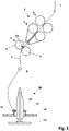
- FIG 1 shows a schematic representation of a longitudinal section of a spinning machine according to the prior art, in particular a ring spinning machine. Shown are examples of individual components of the spinning machine, namely a drafting system 2 and a spinning device 10.
- the drafting system 2 consists of three pairs of rollers, an input roller pair 3, a strap roller pair 4 and an output roller pair 5.
- the output roller pair 5 is formed by an output upper roller 6 and an output lower roller 7.
- the two rollers of a roller pair are opposed to each other pressed and form a nip at their point of contact, the nip K1 being formed by the output roller pair 5 between the output upper roller 6 and the output lower roller 7 .
- the fiber strand 1 entering the drafting system 2 is clamped between the rollers of the pairs of rollers 3 , 4 and 5 by the nip points and drawn due to the different speeds of the pairs of rollers 3 , 4 and 5 .
- the fiber structure 1 is transported through the drafting system 2 at the same time.
- the drafted fiber structure 8 reaches a yarn guide 9 and is then conveyed to the spinning device 10.
- the spinning device 10 consists essentially of a ring rail 14, which carries the spinning ring 12, and a spindle rail 15, on which the bobbin 13 is fastened is.
- the fiber structure 8 reaches the bobbin 13 via a rotor 11.
- To spin the fiber structure 8, the bobbin 13 is set in rotation. Due to the different rotational speeds of the bobbin 13 and the rotor 11, the fiber structure 8 is rotated and a yarn is thereby formed which is wound onto the bobbin 13 by moving the ring rail 14 up and down.
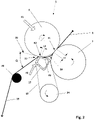
- FIG 2 shows a schematic representation of a longitudinal section of an embodiment according to the invention of a compression device of the drafting system.
- a suction pipe 17 is arranged.
- the suction tube 17 is wrapped around by a sieve element 18 which is designed as an endless belt and is guided over a deflection 24 .
- the screen element 18 forms a second nip point K2 for the drafted fiber bundle with the output top roller 6 .
- the suction pipe 17 with the screen element 18 guided thereon is pressed against the output top roller 6 with the pressing force F2, as a result of which the surface of the output top roller 6 is slightly deformed. This results in the length L2 of the second clamping point K2.
- the shape of the intake manifold 17 is shown as a polygon, but any other shapes such as a triangle, ellipse, etc. are also possible.
- the fiber bundling zone 16 designates the space which is enclosed by the upper exit roller 6, the lower exit roller 7 and the suction tube 17.
- the suction pipe 17 has a suction opening 23 in this fiber bundling zone 16 .
- the suction opening 23 is preferably formed as a slit-shaped opening in the wall of the suction tube 17 .
- the suction pipe 17 is connected to a vacuum source (not shown), this causes over the Suction opening 17 and thus also through the screen element 18 sliding over the suction opening 17 air is sucked out of the fiber bundling zone 16 .
- the resulting air flow pulls the stretched fiber structure towards the screen element 18, with individual fibers protruding from the stretched fiber structure being conveyed to the suction opening 23 and thus clinging to the stretched fiber structure.
- the screen element 18 is set in motion by the output top roller 6 via the resulting frictional force in the clamping point K2, as a result of which the drafted fiber structure is fed from the fiber bundling zone 16 to the second clamping point K2.
- the compacted fiber structure 19 then leaves the screen element 18 at a detachment point 21, which does not necessarily have to correspond to the end of the clamping point K2.
- the compacted fiber structure 19 is then fed via a deflection point 20 to the spinning device or to the thread guide arranged in front of the spinning device.
- the geometry of the suction pipe 17 and the arrangement of the deflection point 20 make it possible to restore the inlet geometry required for the spinning device to function properly, despite the additional arrangement of the compression device.
- the thread guide 9 assigned to the spinning device can be used as a deflection point, which eliminates the additional deflection point 20.
- an angle ⁇ at which the compacted fiber structure 19 leaves the screening element 18 at the detachment point 21 is designed to be smaller than 70°.
- the angle ⁇ is 50°.
- the angle ⁇ corresponds to the included angle between the running direction of the compacted fiber structure 19 after the detachment point 21 and a tangent 22 applied to the surface of the output top roller 6 in the second nip K2.
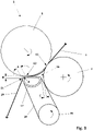
- FIG 3 shows a schematic representation of a longitudinal section of a further embodiment according to the invention of the compression device of the drafting system.
- the stretched fiber structure After leaving the first clamping point K1, the stretched fiber structure meets a screen element 18 which runs around a suction pipe 17 and a deflection 24.
- the suction pipe 17 is arranged at a distance C of less than 2 mm from the surface of the bottom roller 7 to ensure a smooth transition of the fiber structure from the first clamping point K1 to the screen element 18 .
- the distance C is measured in the radial direction of the lower exit roller 7 from the surface of the lower exit roller 7 .
- the screen element 18 brings the drafted fiber structure to the second nip point K2, which is formed by the output top roller 6 and the screen element 18.
- the screen element 18 is set in motion by the output top roller 6 via the frictional force that arises in the nip point K2, as a result of which the drafted fiber structure is fed from the fiber bundling zone 16 to the second nip point K2.
- the compacted fiber strand 19 then leaves the screen element 18 at a detachment point 21.
- the suction pipe 17 is designed in such a way that the detachment point 21 is arranged in the radial direction of the output top roller 6 in the second nip K2 from a surface of the output top roller 6 at a distance B of less than 4 mm.
- a length A which the compressed fiber structure 19 covers from the second clamping point K2 to the detachment point 21 on the screen element 18 is less than 10 mm.
- the suction tube is designed with a radius R of less than 10 mm in the area of the detachment point.
Landscapes
- Engineering & Computer Science (AREA)
- Mechanical Engineering (AREA)
- Textile Engineering (AREA)
- Spinning Or Twisting Of Yarns (AREA)
Claims (14)
- Dispositif d'étirage (2) pour une machine à filer, comportant une paire de cylindres délivreurs (5), qui est formée par un cylindre délivreur supérieur (6) et un cylindre délivreur inférieur (7), et avec un compactage de fibres disposé en aval d'une paire de cylindres délivreurs (5) du dispositif d'étirage (2) pour le compactage d'un ensemble de fibres étiré, qui présente un dispositif de compactage pneumatique avec une zone de mise en faisceau de fibres (16) et avec un tube d'aspiration (17) entouré par un élément de tamisage (18) et pouvant être aspiré, dans lequel la zone de mise en faisceau de fibres (16) est limitée par deux points de pincement (K1, K2) avec une longueur respective (L1, L2), dans lequel un premier point de pincement (K1) est défini par les deux cylindres (6, 7) de la paire de cylindres délivreurs (5), et un deuxième point de pincement (K2) est défini par le cylindre délivreur supérieur (6) et l'élément de tamisage (18), caractérisé en ce que , vue dans la direction longitudinale de l'ensemble de fibres (1, 19), la longueur (L1) du premier point de pincement (K1) est supérieure à la longueur (L2) du deuxième point de pincement (K2) et en ce qu'une force de pression (F2) du deuxième point de pincement (K2) est inférieure à une force de pression (F1) du premier point de pincement (K1).
- Dispositif d'étirage (2) selon la revendication 1, caractérisé en ce qu'un point de détachement (21) est prévu à la suite du deuxième point de pincement (K2), auquel l'ensemble de fibres (8) compacté se détache de l'élément de tamisage (18) en cas d'utilisation prédéterminée, et en ce qu'un point de renvoi (20) pour l'ensemble de fibres (8) compacté est disposé en aval de la zone de compactage, et un angle (α) entre une tangente (22) au cylindre délivreur supérieur (6) au niveau du deuxième point de pincement (K2) et la trajectoire de l'ensemble de fibres (8) entre le point de détachement (21) et le point de renvoi (20) est inférieur à 90°, de préférence inférieur à 70°.
- Dispositif d'étirage (2) selon la revendication 2, caractérisé en ce que le point de renvoi (20) est formé par une barre de renvoi ou un guide-fils.
- Dispositif d'étirage (2) selon l'une quelconque ou plusieurs des revendications précédentes, caractérisé en ce que la force de pression (F1) du premier point de pincement (K1) est de 75 N à 125 N et la force de pression (F2) du deuxième point de pincement (K2) est de 8 N à 20 N.
- Dispositif d'étirage (2) selon l'une quelconque ou plusieurs des revendications précédentes, caractérisé en ce qu'il est formée entre le premier point de pincement (K1) et le deuxième point de pincement (K2) une longueur de pincement qui est inférieure à une longueur de fibres discontinues moyenne de l'ensemble de fibres prévu sur le dispositif d'étirage pour le compactage.
- Dispositif d'étirage (2) selon la revendication 5, caractérisé en ce que la longueur de pincement est de 12 mm à 20 mm.
- Dispositif d'étirage (2) selon l'une quelconque ou plusieurs des revendications 2 à 6, caractérisé en ce que le tube d'aspiration (17) présente un rayon (R) inférieur à 10 mm après le deuxième point de pincement (K2) dans la zone du point de détachement (21).
- Dispositif d'étirage (2) selon l'une quelconque ou plusieurs des revendications 2 à 7, caractérisé en ce qu'une distance (A) entre le point de détachement (21) sur la surface de l'élément de tamisage (18) et le deuxième point de pincement (K2) est inférieure à 10 mm.
- Dispositif d'étirage (2) selon l'une quelconque ou plusieurs des revendications 2 à 8, caractérisé en ce qu'une distance (B) du point de détachement (21) dans la direction radiale du cylindre délivreur supérieur (6) dans le deuxième point de pincement (K2) par rapport à une surface du cylindre délivreur supérieur (6) est inférieure à 4 mm.
- Dispositif d'étirage (2) selon l'une quelconque ou plusieurs des revendications 2 à 8, caractérisé en ce qu'une distance (C) du tube d'aspiration (16) dans la direction radiale du cylindre délivreur inférieur (7) par rapport à la surface de cylindre du cylindre délivreur inférieur (7) est inférieure à 2 mm.
- Dispositif d'étirage (2) selon l'une quelconque ou plusieurs des revendications précédentes, caractérisé en ce que le dispositif de compactage est disposé sur le dispositif d'étirage (2).
- Dispositif d'étirage (2) selon la revendication 8, caractérisé en ce que le dispositif de compactage est disposé sur un bras de pression du dispositif d'étirage (2).
- Dispositif d'étirage (2) selon l'une quelconque ou plusieurs des revendications précédentes, caractérisé en ce que le dispositif de compactage est pressé contre le cylindre délivreur supérieur (6) du deuxième point de pincement (K2) au moyen d'un dispositif de réglage.
- Procédé pour compacter un ensemble de fibres (8) dans une machine à filer avec un dispositif d'étirage (2) comportant une paire de cylindres délivreurs (5), qui est formée par un cylindre délivreur supérieur (6) et un cylindre délivreur inférieur (7), dans lequel l'ensemble de fibres (8) est acheminé à travers la paire de cylindres délivreurs (5) vers une compactage de fibres disposé en aval, qui présente un dispositif de compactage pneumatique avec une zone de mise en faisceau de fibres (16) et avec un tube d'aspiration (17) entouré par un élément de tamisage (18) et pouvant être aspiré, dans lequel la zone de mise en faisceau de fibres (15) est limitée par deux points de pincement (K1, K2) avec une longueur respective (L1, L2), dans lequel le cylindre délivreur supérieur (6) et le cylindre délivreur inférieur (7) définissent un premier point de pincement (K1), et le cylindre délivreur supérieur (6) de la paire de cylindres délivreurs (5) et l'élément de tamisage (18) définissent un deuxième point de pincement (K2), caractérisé en ce que les fibres de l'ensemble de fibres sont acheminées à travers le premier point de pincement (K1) vers l'élément de tamisage (18) et sont prises en charge de l'élément de tamisage (18) par le deuxième point de pincement (K2), dans lequel le guidage des fibres est déterminé par une longueur (L1) plus grande du premier point de pincement (K1) par rapport à la longueur (L2) du deuxième point de pincement (K2) et la force de pression (F2) générée au deuxième point de pincement (K2) est plus faible qu'une force de pression (F1) générée au premier point de pincement (K1).
Applications Claiming Priority (2)
| Application Number | Priority Date | Filing Date | Title |
|---|---|---|---|
| CH01527/17A CH714444A1 (de) | 2017-12-15 | 2017-12-15 | Streckwerk für eine Spinnmaschine mit einer Verdichtungsvorrichtung. |
| PCT/EP2018/083319 WO2019115267A1 (fr) | 2017-12-15 | 2018-12-03 | Banc d'étirage d'un métier à filer, muni d'un dispositif de compression |
Publications (2)
| Publication Number | Publication Date |
|---|---|
| EP3724382A1 EP3724382A1 (fr) | 2020-10-21 |
| EP3724382B1 true EP3724382B1 (fr) | 2023-01-25 |
Family
ID=64664247
Family Applications (1)
| Application Number | Title | Priority Date | Filing Date |
|---|---|---|---|
| EP18815976.8A Active EP3724382B1 (fr) | 2017-12-15 | 2018-12-03 | Banc d'étirage d'un métier à filer, avec un dispositif de compactage |
Country Status (4)
| Country | Link |
|---|---|
| EP (1) | EP3724382B1 (fr) |
| CN (2) | CN111448344A (fr) |
| CH (1) | CH714444A1 (fr) |
| WO (1) | WO2019115267A1 (fr) |
Families Citing this family (1)
| Publication number | Priority date | Publication date | Assignee | Title |
|---|---|---|---|---|
| CH714444A1 (de) * | 2017-12-15 | 2019-06-28 | Rieter Ag Maschf | Streckwerk für eine Spinnmaschine mit einer Verdichtungsvorrichtung. |
Family Cites Families (10)
| Publication number | Priority date | Publication date | Assignee | Title |
|---|---|---|---|---|
| DE10050089C2 (de) | 2000-03-08 | 2002-06-27 | Zinser Textilmaschinen Gmbh | Streckwerk für eine Spinnereimaschine |
| US4976096A (en) * | 1989-06-15 | 1990-12-11 | The United States Of America As Represented By The Secretary Of Agriculture | System for producing core/wrap yarn |
| DE19838762B4 (de) * | 1998-08-26 | 2009-04-16 | Maschinenfabrik Rieter Ag | Spinnmaschine mit einer Vielzahl von Spinnstellen |
| DE19922861A1 (de) * | 1999-05-19 | 2000-11-23 | Stahlecker Fritz | Verfahren zum Verdichten eines verstreckten Faserverbandes |
| JP2001279539A (ja) * | 2000-03-08 | 2001-10-10 | Zinser Textilmas Gmbh | 精紡機のドラフト機構 |
| DE10019436A1 (de) * | 2000-04-19 | 2001-10-25 | Zinser Textilmaschinen Gmbh | Streckwerk für eine Spinnereimaschine |
| DE10053698A1 (de) * | 2000-10-23 | 2002-05-02 | Stahlecker Fritz | Vorrichtung an einer Spinnmaschine zum Verdichten eines Faserverbandes |
| DE10343316A1 (de) * | 2003-09-10 | 2005-04-14 | Wilhelm Stahlecker Gmbh | Vorrichtung an einer Spinnmaschine zum Verdichten eines Faserverbandes |
| DE102007006282A1 (de) * | 2007-02-01 | 2008-08-07 | Wilhelm Stahlecker Gmbh | Streckwerk mit Verdichtungszone |
| CH714444A1 (de) * | 2017-12-15 | 2019-06-28 | Rieter Ag Maschf | Streckwerk für eine Spinnmaschine mit einer Verdichtungsvorrichtung. |
-
2017
- 2017-12-15 CH CH01527/17A patent/CH714444A1/de not_active Application Discontinuation
-
2018
- 2018-12-03 CN CN201880080017.9A patent/CN111448344A/zh active Pending
- 2018-12-03 WO PCT/EP2018/083319 patent/WO2019115267A1/fr not_active Ceased
- 2018-12-03 EP EP18815976.8A patent/EP3724382B1/fr active Active
- 2018-12-12 CN CN201822089459.XU patent/CN209652486U/zh active Active
Also Published As
| Publication number | Publication date |
|---|---|
| CN209652486U (zh) | 2019-11-19 |
| EP3724382A1 (fr) | 2020-10-21 |
| WO2019115267A1 (fr) | 2019-06-20 |
| CN111448344A (zh) | 2020-07-24 |
| CH714444A1 (de) | 2019-06-28 |
Similar Documents
| Publication | Publication Date | Title |
|---|---|---|
| DE4323472C2 (de) | Doppelriemchen-Streckwerk | |
| EP0986659B1 (fr) | Procede et metier a filer destines a la production de fils a ame | |
| EP1134309B1 (fr) | Dispositif d'étirage suit par une zone de condensation dans une machine de filature | |
| DE10344163B9 (de) | Verfahren und Vorrichtung zur Herstellung von Coregarn oder Corescheinzwirn | |
| DE10236450A1 (de) | Spinnmaschine mit einem Mehrstufen-Verdichtungs-Streckwerk | |
| DE10050089C2 (de) | Streckwerk für eine Spinnereimaschine | |
| EP3115486B1 (fr) | Banc d'étirage comprenant plusieurs guides de bandes fibreuses | |
| EP3724383B1 (fr) | Dispositif d'étirage pour un métier à filer comprenant un dispositif de compactage | |
| DE102017130219A1 (de) | Spinnereimaschine und Verdichtungsvorrichtung | |
| EP3724382B1 (fr) | Banc d'étirage d'un métier à filer, avec un dispositif de compactage | |
| DE102007003525A1 (de) | Saugkanal für eine Faserbündelungseinrichtung | |
| EP3724385B1 (fr) | Banc d'étirage pour machine à filer ayant un dispositif de compactage et procédé de compactage d'un ruban de fibres | |
| DE10058892A1 (de) | Vorrichtung an einer Spinnmaschine zum Verdichten eines Faserverbandes | |
| DE102017130215A1 (de) | Streckwerk für eine Spinnereimaschine | |
| DE10008130A1 (de) | Vorrichtung an einer Spinnmaschine zum Verdichten eines Faserverbandes | |
| DE10005387A1 (de) | Vorrichtung an einer Spinnmaschine zum Verdichten eines Faserverbandes | |
| DE10019436A1 (de) | Streckwerk für eine Spinnereimaschine | |
| DE102013113308A1 (de) | Textilmaschine mit variablem Anspannverzug | |
| DE10214641B4 (de) | Pneumatische Verdichtungseinrichtung für einen Faserverband und Verfahren zum pneumatischen Verdichten eines Faserverbandes | |
| DE10127741A1 (de) | Streckwerk für eine Spinnereimaschine | |
| EP3688209B1 (fr) | Dispositif condenseur | |
| DE102007063263A1 (de) | Saugkanal für eine Faserbündelungseinrichtung | |
| DE102013108094A1 (de) | Spinnmaschine und Falschdralleinrichtung | |
| DE102017130221A1 (de) | Streckwerk für eine Spinnereimaschine und Verdichtungsvorrichtung | |
| DE102016106207A1 (de) | Saugkörper für eine pneumatisch arbeitende Faserverdichtungseinrichtung sowie damit ausgestattete Spinnereimaschine |
Legal Events
| Date | Code | Title | Description |
|---|---|---|---|
| STAA | Information on the status of an ep patent application or granted ep patent |
Free format text: STATUS: UNKNOWN |
|
| STAA | Information on the status of an ep patent application or granted ep patent |
Free format text: STATUS: THE INTERNATIONAL PUBLICATION HAS BEEN MADE |
|
| PUAI | Public reference made under article 153(3) epc to a published international application that has entered the european phase |
Free format text: ORIGINAL CODE: 0009012 |
|
| STAA | Information on the status of an ep patent application or granted ep patent |
Free format text: STATUS: REQUEST FOR EXAMINATION WAS MADE |
|
| 17P | Request for examination filed |
Effective date: 20200701 |
|
| AK | Designated contracting states |
Kind code of ref document: A1 Designated state(s): AL AT BE BG CH CY CZ DE DK EE ES FI FR GB GR HR HU IE IS IT LI LT LU LV MC MK MT NL NO PL PT RO RS SE SI SK SM TR |
|
| AX | Request for extension of the european patent |
Extension state: BA ME |
|
| DAV | Request for validation of the european patent (deleted) | ||
| DAX | Request for extension of the european patent (deleted) | ||
| GRAP | Despatch of communication of intention to grant a patent |
Free format text: ORIGINAL CODE: EPIDOSNIGR1 |
|
| STAA | Information on the status of an ep patent application or granted ep patent |
Free format text: STATUS: GRANT OF PATENT IS INTENDED |
|
| INTG | Intention to grant announced |
Effective date: 20220802 |
|
| GRAS | Grant fee paid |
Free format text: ORIGINAL CODE: EPIDOSNIGR3 |
|
| GRAA | (expected) grant |
Free format text: ORIGINAL CODE: 0009210 |
|
| STAA | Information on the status of an ep patent application or granted ep patent |
Free format text: STATUS: THE PATENT HAS BEEN GRANTED |
|
| AK | Designated contracting states |
Kind code of ref document: B1 Designated state(s): AL AT BE BG CH CY CZ DE DK EE ES FI FR GB GR HR HU IE IS IT LI LT LU LV MC MK MT NL NO PL PT RO RS SE SI SK SM TR |
|
| REG | Reference to a national code |
Ref country code: GB Ref legal event code: FG4D Free format text: NOT ENGLISH |
|
| REG | Reference to a national code |
Ref country code: CH Ref legal event code: EP |
|
| REG | Reference to a national code |
Ref country code: AT Ref legal event code: REF Ref document number: 1545964 Country of ref document: AT Kind code of ref document: T Effective date: 20230215 Ref country code: IE Ref legal event code: FG4D Free format text: LANGUAGE OF EP DOCUMENT: GERMAN |
|
| REG | Reference to a national code |
Ref country code: DE Ref legal event code: R096 Ref document number: 502018011526 Country of ref document: DE |
|
| REG | Reference to a national code |
Ref country code: LT Ref legal event code: MG9D |
|
| REG | Reference to a national code |
Ref country code: NL Ref legal event code: MP Effective date: 20230125 |
|
| P01 | Opt-out of the competence of the unified patent court (upc) registered |
Effective date: 20230329 |
|
| PG25 | Lapsed in a contracting state [announced via postgrant information from national office to epo] |
Ref country code: NL Free format text: LAPSE BECAUSE OF FAILURE TO SUBMIT A TRANSLATION OF THE DESCRIPTION OR TO PAY THE FEE WITHIN THE PRESCRIBED TIME-LIMIT Effective date: 20230125 |
|
| PG25 | Lapsed in a contracting state [announced via postgrant information from national office to epo] |
Ref country code: RS Free format text: LAPSE BECAUSE OF FAILURE TO SUBMIT A TRANSLATION OF THE DESCRIPTION OR TO PAY THE FEE WITHIN THE PRESCRIBED TIME-LIMIT Effective date: 20230125 Ref country code: PT Free format text: LAPSE BECAUSE OF FAILURE TO SUBMIT A TRANSLATION OF THE DESCRIPTION OR TO PAY THE FEE WITHIN THE PRESCRIBED TIME-LIMIT Effective date: 20230525 Ref country code: NO Free format text: LAPSE BECAUSE OF FAILURE TO SUBMIT A TRANSLATION OF THE DESCRIPTION OR TO PAY THE FEE WITHIN THE PRESCRIBED TIME-LIMIT Effective date: 20230425 Ref country code: LV Free format text: LAPSE BECAUSE OF FAILURE TO SUBMIT A TRANSLATION OF THE DESCRIPTION OR TO PAY THE FEE WITHIN THE PRESCRIBED TIME-LIMIT Effective date: 20230125 Ref country code: LT Free format text: LAPSE BECAUSE OF FAILURE TO SUBMIT A TRANSLATION OF THE DESCRIPTION OR TO PAY THE FEE WITHIN THE PRESCRIBED TIME-LIMIT Effective date: 20230125 Ref country code: HR Free format text: LAPSE BECAUSE OF FAILURE TO SUBMIT A TRANSLATION OF THE DESCRIPTION OR TO PAY THE FEE WITHIN THE PRESCRIBED TIME-LIMIT Effective date: 20230125 Ref country code: ES Free format text: LAPSE BECAUSE OF FAILURE TO SUBMIT A TRANSLATION OF THE DESCRIPTION OR TO PAY THE FEE WITHIN THE PRESCRIBED TIME-LIMIT Effective date: 20230125 |
|
| PG25 | Lapsed in a contracting state [announced via postgrant information from national office to epo] |
Ref country code: SE Free format text: LAPSE BECAUSE OF FAILURE TO SUBMIT A TRANSLATION OF THE DESCRIPTION OR TO PAY THE FEE WITHIN THE PRESCRIBED TIME-LIMIT Effective date: 20230125 Ref country code: PL Free format text: LAPSE BECAUSE OF FAILURE TO SUBMIT A TRANSLATION OF THE DESCRIPTION OR TO PAY THE FEE WITHIN THE PRESCRIBED TIME-LIMIT Effective date: 20230125 Ref country code: IS Free format text: LAPSE BECAUSE OF FAILURE TO SUBMIT A TRANSLATION OF THE DESCRIPTION OR TO PAY THE FEE WITHIN THE PRESCRIBED TIME-LIMIT Effective date: 20230525 Ref country code: GR Free format text: LAPSE BECAUSE OF FAILURE TO SUBMIT A TRANSLATION OF THE DESCRIPTION OR TO PAY THE FEE WITHIN THE PRESCRIBED TIME-LIMIT Effective date: 20230426 Ref country code: FI Free format text: LAPSE BECAUSE OF FAILURE TO SUBMIT A TRANSLATION OF THE DESCRIPTION OR TO PAY THE FEE WITHIN THE PRESCRIBED TIME-LIMIT Effective date: 20230125 |
|
| REG | Reference to a national code |
Ref country code: DE Ref legal event code: R097 Ref document number: 502018011526 Country of ref document: DE |
|
| PG25 | Lapsed in a contracting state [announced via postgrant information from national office to epo] |
Ref country code: SM Free format text: LAPSE BECAUSE OF FAILURE TO SUBMIT A TRANSLATION OF THE DESCRIPTION OR TO PAY THE FEE WITHIN THE PRESCRIBED TIME-LIMIT Effective date: 20230125 Ref country code: RO Free format text: LAPSE BECAUSE OF FAILURE TO SUBMIT A TRANSLATION OF THE DESCRIPTION OR TO PAY THE FEE WITHIN THE PRESCRIBED TIME-LIMIT Effective date: 20230125 Ref country code: EE Free format text: LAPSE BECAUSE OF FAILURE TO SUBMIT A TRANSLATION OF THE DESCRIPTION OR TO PAY THE FEE WITHIN THE PRESCRIBED TIME-LIMIT Effective date: 20230125 Ref country code: DK Free format text: LAPSE BECAUSE OF FAILURE TO SUBMIT A TRANSLATION OF THE DESCRIPTION OR TO PAY THE FEE WITHIN THE PRESCRIBED TIME-LIMIT Effective date: 20230125 Ref country code: CZ Free format text: LAPSE BECAUSE OF FAILURE TO SUBMIT A TRANSLATION OF THE DESCRIPTION OR TO PAY THE FEE WITHIN THE PRESCRIBED TIME-LIMIT Effective date: 20230125 |
|
| PG25 | Lapsed in a contracting state [announced via postgrant information from national office to epo] |
Ref country code: SK Free format text: LAPSE BECAUSE OF FAILURE TO SUBMIT A TRANSLATION OF THE DESCRIPTION OR TO PAY THE FEE WITHIN THE PRESCRIBED TIME-LIMIT Effective date: 20230125 |
|
| PLBE | No opposition filed within time limit |
Free format text: ORIGINAL CODE: 0009261 |
|
| STAA | Information on the status of an ep patent application or granted ep patent |
Free format text: STATUS: NO OPPOSITION FILED WITHIN TIME LIMIT |
|
| 26N | No opposition filed |
Effective date: 20231026 |
|
| PG25 | Lapsed in a contracting state [announced via postgrant information from national office to epo] |
Ref country code: SI Free format text: LAPSE BECAUSE OF FAILURE TO SUBMIT A TRANSLATION OF THE DESCRIPTION OR TO PAY THE FEE WITHIN THE PRESCRIBED TIME-LIMIT Effective date: 20230125 |
|
| REG | Reference to a national code |
Ref country code: CH Ref legal event code: PL |
|
| PG25 | Lapsed in a contracting state [announced via postgrant information from national office to epo] |
Ref country code: LU Free format text: LAPSE BECAUSE OF NON-PAYMENT OF DUE FEES Effective date: 20231203 |
|
| PG25 | Lapsed in a contracting state [announced via postgrant information from national office to epo] |
Ref country code: MC Free format text: LAPSE BECAUSE OF FAILURE TO SUBMIT A TRANSLATION OF THE DESCRIPTION OR TO PAY THE FEE WITHIN THE PRESCRIBED TIME-LIMIT Effective date: 20230125 |
|
| GBPC | Gb: european patent ceased through non-payment of renewal fee |
Effective date: 20231203 |
|
| REG | Reference to a national code |
Ref country code: BE Ref legal event code: MM Effective date: 20231231 |
|
| PG25 | Lapsed in a contracting state [announced via postgrant information from national office to epo] |
Ref country code: MC Free format text: LAPSE BECAUSE OF FAILURE TO SUBMIT A TRANSLATION OF THE DESCRIPTION OR TO PAY THE FEE WITHIN THE PRESCRIBED TIME-LIMIT Effective date: 20230125 Ref country code: LU Free format text: LAPSE BECAUSE OF NON-PAYMENT OF DUE FEES Effective date: 20231203 |
|
| REG | Reference to a national code |
Ref country code: IE Ref legal event code: MM4A |
|
| PG25 | Lapsed in a contracting state [announced via postgrant information from national office to epo] |
Ref country code: IE Free format text: LAPSE BECAUSE OF NON-PAYMENT OF DUE FEES Effective date: 20231203 |
|
| PG25 | Lapsed in a contracting state [announced via postgrant information from national office to epo] |
Ref country code: GB Free format text: LAPSE BECAUSE OF NON-PAYMENT OF DUE FEES Effective date: 20231203 |
|
| PG25 | Lapsed in a contracting state [announced via postgrant information from national office to epo] |
Ref country code: BE Free format text: LAPSE BECAUSE OF NON-PAYMENT OF DUE FEES Effective date: 20231231 |
|
| PG25 | Lapsed in a contracting state [announced via postgrant information from national office to epo] |
Ref country code: FR Free format text: LAPSE BECAUSE OF NON-PAYMENT OF DUE FEES Effective date: 20231231 |
|
| PG25 | Lapsed in a contracting state [announced via postgrant information from national office to epo] |
Ref country code: CH Free format text: LAPSE BECAUSE OF NON-PAYMENT OF DUE FEES Effective date: 20231231 |
|
| PG25 | Lapsed in a contracting state [announced via postgrant information from national office to epo] |
Ref country code: IE Free format text: LAPSE BECAUSE OF NON-PAYMENT OF DUE FEES Effective date: 20231203 Ref country code: GB Free format text: LAPSE BECAUSE OF NON-PAYMENT OF DUE FEES Effective date: 20231203 Ref country code: FR Free format text: LAPSE BECAUSE OF NON-PAYMENT OF DUE FEES Effective date: 20231231 Ref country code: CH Free format text: LAPSE BECAUSE OF NON-PAYMENT OF DUE FEES Effective date: 20231231 Ref country code: BE Free format text: LAPSE BECAUSE OF NON-PAYMENT OF DUE FEES Effective date: 20231231 |
|
| PG25 | Lapsed in a contracting state [announced via postgrant information from national office to epo] |
Ref country code: BG Free format text: LAPSE BECAUSE OF FAILURE TO SUBMIT A TRANSLATION OF THE DESCRIPTION OR TO PAY THE FEE WITHIN THE PRESCRIBED TIME-LIMIT Effective date: 20230125 |
|
| PG25 | Lapsed in a contracting state [announced via postgrant information from national office to epo] |
Ref country code: BG Free format text: LAPSE BECAUSE OF FAILURE TO SUBMIT A TRANSLATION OF THE DESCRIPTION OR TO PAY THE FEE WITHIN THE PRESCRIBED TIME-LIMIT Effective date: 20230125 |
|
| REG | Reference to a national code |
Ref country code: AT Ref legal event code: MM01 Ref document number: 1545964 Country of ref document: AT Kind code of ref document: T Effective date: 20231203 |
|
| PG25 | Lapsed in a contracting state [announced via postgrant information from national office to epo] |
Ref country code: AT Free format text: LAPSE BECAUSE OF NON-PAYMENT OF DUE FEES Effective date: 20231203 |
|
| PG25 | Lapsed in a contracting state [announced via postgrant information from national office to epo] |
Ref country code: CY Free format text: LAPSE BECAUSE OF FAILURE TO SUBMIT A TRANSLATION OF THE DESCRIPTION OR TO PAY THE FEE WITHIN THE PRESCRIBED TIME-LIMIT; INVALID AB INITIO Effective date: 20181203 |
|
| PG25 | Lapsed in a contracting state [announced via postgrant information from national office to epo] |
Ref country code: HU Free format text: LAPSE BECAUSE OF FAILURE TO SUBMIT A TRANSLATION OF THE DESCRIPTION OR TO PAY THE FEE WITHIN THE PRESCRIBED TIME-LIMIT; INVALID AB INITIO Effective date: 20181203 |
|
| PGFP | Annual fee paid to national office [announced via postgrant information from national office to epo] |
Ref country code: TR Payment date: 20251127 Year of fee payment: 8 |
|
| PGFP | Annual fee paid to national office [announced via postgrant information from national office to epo] |
Ref country code: DE Payment date: 20251230 Year of fee payment: 8 |