EP3724455B1 - Dämpfungsvorrichtung - Google Patents
Dämpfungsvorrichtung Download PDFInfo
- Publication number
- EP3724455B1 EP3724455B1 EP18836279.2A EP18836279A EP3724455B1 EP 3724455 B1 EP3724455 B1 EP 3724455B1 EP 18836279 A EP18836279 A EP 18836279A EP 3724455 B1 EP3724455 B1 EP 3724455B1
- Authority
- EP
- European Patent Office
- Prior art keywords
- damping device
- assembly
- blade
- module
- rotor
- Prior art date
- Legal status (The legal status is an assumption and is not a legal conclusion. Google has not performed a legal analysis and makes no representation as to the accuracy of the status listed.)
- Active
Links
Images



Classifications
-
- F—MECHANICAL ENGINEERING; LIGHTING; HEATING; WEAPONS; BLASTING
- F04—POSITIVE - DISPLACEMENT MACHINES FOR LIQUIDS; PUMPS FOR LIQUIDS OR ELASTIC FLUIDS
- F04D—NON-POSITIVE-DISPLACEMENT PUMPS
- F04D29/00—Details, component parts, or accessories
- F04D29/66—Combating cavitation, whirls, noise, vibration or the like; Balancing
- F04D29/661—Combating cavitation, whirls, noise, vibration or the like; Balancing especially adapted for elastic fluid pumps
- F04D29/668—Combating cavitation, whirls, noise, vibration or the like; Balancing especially adapted for elastic fluid pumps damping or preventing mechanical vibrations
-
- F—MECHANICAL ENGINEERING; LIGHTING; HEATING; WEAPONS; BLASTING
- F01—MACHINES OR ENGINES IN GENERAL; ENGINE PLANTS IN GENERAL; STEAM ENGINES
- F01D—NON-POSITIVE DISPLACEMENT MACHINES OR ENGINES, e.g. STEAM TURBINES
- F01D5/00—Blades; Blade-carrying members; Heating, heat-insulating, cooling or antivibration means on the blades or the members
- F01D5/12—Blades
- F01D5/22—Blade-to-blade connections, e.g. for damping vibrations
-
- F—MECHANICAL ENGINEERING; LIGHTING; HEATING; WEAPONS; BLASTING
- F01—MACHINES OR ENGINES IN GENERAL; ENGINE PLANTS IN GENERAL; STEAM ENGINES
- F01D—NON-POSITIVE DISPLACEMENT MACHINES OR ENGINES, e.g. STEAM TURBINES
- F01D5/00—Blades; Blade-carrying members; Heating, heat-insulating, cooling or antivibration means on the blades or the members
- F01D5/12—Blades
- F01D5/26—Antivibration means not restricted to blade form or construction or to blade-to-blade connections or to the use of particular materials
-
- F—MECHANICAL ENGINEERING; LIGHTING; HEATING; WEAPONS; BLASTING
- F01—MACHINES OR ENGINES IN GENERAL; ENGINE PLANTS IN GENERAL; STEAM ENGINES
- F01D—NON-POSITIVE DISPLACEMENT MACHINES OR ENGINES, e.g. STEAM TURBINES
- F01D5/00—Blades; Blade-carrying members; Heating, heat-insulating, cooling or antivibration means on the blades or the members
- F01D5/02—Blade-carrying members, e.g. rotors
- F01D5/10—Anti- vibration means
-
- F—MECHANICAL ENGINEERING; LIGHTING; HEATING; WEAPONS; BLASTING
- F04—POSITIVE - DISPLACEMENT MACHINES FOR LIQUIDS; PUMPS FOR LIQUIDS OR ELASTIC FLUIDS
- F04D—NON-POSITIVE-DISPLACEMENT PUMPS
- F04D29/00—Details, component parts, or accessories
- F04D29/26—Rotors specially for elastic fluids
- F04D29/32—Rotors specially for elastic fluids for axial flow pumps
- F04D29/321—Rotors specially for elastic fluids for axial flow pumps for axial flow compressors
- F04D29/322—Blade mountings
-
- F—MECHANICAL ENGINEERING; LIGHTING; HEATING; WEAPONS; BLASTING
- F05—INDEXING SCHEMES RELATING TO ENGINES OR PUMPS IN VARIOUS SUBCLASSES OF CLASSES F01-F04
- F05D—INDEXING SCHEME FOR ASPECTS RELATING TO NON-POSITIVE-DISPLACEMENT MACHINES OR ENGINES, GAS-TURBINES OR JET-PROPULSION PLANTS
- F05D2220/00—Application
- F05D2220/30—Application in turbines
- F05D2220/36—Application in turbines specially adapted for the fan of turbofan engines
-
- F—MECHANICAL ENGINEERING; LIGHTING; HEATING; WEAPONS; BLASTING
- F05—INDEXING SCHEMES RELATING TO ENGINES OR PUMPS IN VARIOUS SUBCLASSES OF CLASSES F01-F04
- F05D—INDEXING SCHEME FOR ASPECTS RELATING TO NON-POSITIVE-DISPLACEMENT MACHINES OR ENGINES, GAS-TURBINES OR JET-PROPULSION PLANTS
- F05D2230/00—Manufacture
- F05D2230/90—Coating; Surface treatment
-
- F—MECHANICAL ENGINEERING; LIGHTING; HEATING; WEAPONS; BLASTING
- F05—INDEXING SCHEMES RELATING TO ENGINES OR PUMPS IN VARIOUS SUBCLASSES OF CLASSES F01-F04
- F05D—INDEXING SCHEME FOR ASPECTS RELATING TO NON-POSITIVE-DISPLACEMENT MACHINES OR ENGINES, GAS-TURBINES OR JET-PROPULSION PLANTS
- F05D2240/00—Components
- F05D2240/80—Platforms for stationary or moving blades
-
- F—MECHANICAL ENGINEERING; LIGHTING; HEATING; WEAPONS; BLASTING
- F05—INDEXING SCHEMES RELATING TO ENGINES OR PUMPS IN VARIOUS SUBCLASSES OF CLASSES F01-F04
- F05D—INDEXING SCHEME FOR ASPECTS RELATING TO NON-POSITIVE-DISPLACEMENT MACHINES OR ENGINES, GAS-TURBINES OR JET-PROPULSION PLANTS
- F05D2260/00—Function
- F05D2260/96—Preventing, counteracting or reducing vibration or noise
-
- Y—GENERAL TAGGING OF NEW TECHNOLOGICAL DEVELOPMENTS; GENERAL TAGGING OF CROSS-SECTIONAL TECHNOLOGIES SPANNING OVER SEVERAL SECTIONS OF THE IPC; TECHNICAL SUBJECTS COVERED BY FORMER USPC CROSS-REFERENCE ART COLLECTIONS [XRACs] AND DIGESTS
- Y02—TECHNOLOGIES OR APPLICATIONS FOR MITIGATION OR ADAPTATION AGAINST CLIMATE CHANGE
- Y02T—CLIMATE CHANGE MITIGATION TECHNOLOGIES RELATED TO TRANSPORTATION
- Y02T50/00—Aeronautics or air transport
- Y02T50/60—Efficient propulsion technologies, e.g. for aircraft
Definitions
- the invention relates to an assembly comprising a turbomachine rotor module.
- the invention relates more specifically to an assembly for a turbomachine comprising two rotor modules and a damping device.
- a turbine engine rotor module generally comprises one or more stage(s), each stage comprising a disc centered on a longitudinal axis of the turbine engine, corresponding to the axis of rotation of the rotor module.
- the rotation of the disc is generally ensured by a rotary shaft to which it is integrally connected, for example by means of a rotor module pin, the rotary shaft extending along the longitudinal axis of the turbomachine.
- Vanes are mounted on the outer periphery of the disk, and distributed circumferentially, in a regular manner around the longitudinal axis.
- Each vane extends from the disc, and further includes a blade, a platform, a stilt and a root.
- the foot is embedded in a housing of the disk configured for this purpose, the blade is swept by a flow passing through the turbomachine, and the platform forms a portion of the internal surface of the flow path.
- the operating range of a rotor module is limited, in particular because of aeroelastic phenomena.
- the rotor modules of modern turbomachines which have a high aerodynamic load and a reduced number of blades, are more sensitive to this type of phenomenon. In particular, they have reduced margins between the operating zones without instability and the unstable zones. It is nevertheless imperative to guarantee a sufficient margin between the stability domain and that of instability, or to demonstrate that the rotor module can operate in the instability zone without exceeding its endurance limit. This makes it possible to guarantee risk-free operation throughout the life and entire operating range of the turbomachine.
- Operation in the instability zone is characterized by a coupling between the fluid and the structure, the fluid bringing energy to the structure, and the structure responding on its own modes to levels that may exceed the endurance limit of the material constituting the blade. This generates vibratory instabilities which accelerate the wear of the rotor module, and reduce its service life.
- An object of the invention is to damp the vibration modes exhibiting a zero phase shift for all types of turbomachine rotor modules.
- Another object of the invention is to influence the damping of vibration modes with non-zero phase shift, for all types of turbomachine rotor modules.
- Another object of the invention is to propose a damping solution that is simple and easy to implement.
- the mechanical coupling between the first and the second rotor module makes it possible to increase the tangential rigidity of the connection between these two rotors, while allowing a certain axial and radial flexibility of the damping device in order to maximize the contact between the various elements of the together. This makes it possible to limit the instabilities linked to the mode of vibration with zero phase shift, but also to participate in the damping of the modes of vibration with non-zero phase shift.
- such an assembly has the advantage of easy integration into existing turbomachines, whether during manufacture or during maintenance.
- the first rotor module comprises a disk centered on a longitudinal axis of the turbomachine, the first blade being mounted at the outer periphery of the disk from which it extends, and further comprising a blade, a platform, a stilt and a root embedded in a housing of the disc
- the second module comprises a shroud comprising a circumferential extension extending towards the platform of the first vane, the first outer radial surface of the damping device resting with friction on an internal surface of the platform of the first blade, the second external radial surface of the damping device bearing against the circumferential extension of the shroud of the second rotor module.
- the damping device also comprises two shoulders on either side of a notch provided at the level of the internal surface of the damping device, the shoulders bearing against the stilt.
- the invention also relates to a turbomachine comprising an assembly as previously described.
- the upstream and the downstream are defined with respect to the direction of normal air flow through the turbomachine. Furthermore, a longitudinal axis X-X of the turbomachine is defined.
- the axial direction corresponds to the direction of the longitudinal axis X-X of the turbomachine
- a radial direction is a direction which is perpendicular to this longitudinal axis X-X of the turbomachine and which passes through said longitudinal axis X-X of the turbomachine
- a direction circumferential corresponds to the direction of a flat and closed curved line, all the points of which are at equal distance from the longitudinal axis X-X of the turbomachine.
- the terms “internal (or interior)” and “external (or exterior)”, respectively, are used in reference to a radial direction so that the internal (i.e. radially internal) part or face d an element is closer to the longitudinal axis X-X of the turbomachine than the outer part or face (i.e. radially outer) of the same element.
- the first outer radial surface 41 extends along a plane substantially parallel to the plane in which the second outer radial surface 42 extends.
- these two planes are inclined with respect to each other d an angle close to 180°, for example between 165° and 195°.
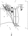
- the first rotor module is a fan 2
- the second rotor module is a low pressure compressor 3, located immediately downstream of the fan 2.
- the fan 2 and the low-pressure compressor 3 comprise a disk 21, 31 centered on the longitudinal axis XX of the turbomachine, the first 20 and the second blade 30 being respectively mounted at the outer periphery of the disk 21, 31, and further comprising a blade 23, 33, a platform 25, 35 a stilt 27, 37 and a foot 29, 39 embedded in a housing 210, 310 of the disc 21, 31.
- the distance separating the foot 29, 39 from the end of the blade 23, 33 constitute the respective lengths of the first 20 and of the second blade 30.
- the length of the first blade 20 and second blade 30 is therefore considered here as substantially radially with respect to the longitudinal axis XX of rotation of the rotor modules 2 , 3.
- fan 2 and low pressure compressor 3 comprise a plurality of blades 20, 30 distributed circumferentially around the longitudinal axis XX.
- the low pressure compressor 3 further comprises an annular shroud 32 also centered on the longitudinal axis XX.
- the shroud 32 comprises a circumferential extension 34, also annular, extending towards the platform 25 of the first blade 20.
- This annular extension 34 carries radial sealing wipers 36 configured to prevent losses of air flow from the flow path 5.
- shroud 32 is fixed to the disc 21 of the fan 2 by means of fasteners 22 distributed circumferentially around the longitudinal axis XX.
- fasteners 22 can for example be bolted connections 22.
- fasteners 22 can be made by hooping with which is associated an anti-rotation device and/or an axial locking system.
- the assembly formed by the fan 2 and the compressor 3 is rotated by a rotating shaft 6, called the low pressure shaft, to which the fan 2 and the low pressure compressor 3 are integrally connected, by means of a rotor pin 60, the low pressure shaft 6 also being connected to a low pressure turbine 7, downstream of the turbomachine, and extending along the longitudinal axis XX of the turbomachine.
- the fan 2 draws in air, all or part of which is compressed by the low pressure compressor 3.
- the compressed air then circulates in a high pressure compressor (not shown) before being mixed with fuel, then ignited within the combustion chamber (not shown), to finally be successively expanded in the high turbine (not shown) and the low pressure turbine 7.
- the opposing compression forces upstream, and expansion downstream give rise to aeroelastic phenomena of flutter, which couple the aerodynamic forces on the blades 20, 30, and the vibration movements in bending and torsion in the blades 20, 30.
- This flutter leads in particular to intense torsional forces within the low pressure shaft 6 which are passed on to the fan 2 and to the low pressure compressor 3.
- the blades 20, 30 are then subjected to tangential beats, in particular according to a mode vibration at zero phase shift.
- a mode vibration at zero phase shift This is in fact a bending mode with an inter-blade phase shift 20, 30 of zero, implying a non-zero moment on the low-pressure shaft 6, the natural frequency of which is approximately one and a half times greater than that of first harmonic of vibration, and whose distortion has a nodal line at mid-height of the blade 20, 30.
- Such vibrations limit the mechanical strength of the fan 2 and of the low-pressure compressor 3, accelerate the wear of the turbomachine, and reduce its service life.
- the tangential movement by floating of the blade 20 of the fan 2 is different from that of the shroud 32 of the low pressure compressor 3.
- the length of the blades 20 of the fan 2 being greater than that of the blades 30 of the low pressure compressor 3
- the tangential bending moment caused by the beats of a fan blade 20 2 is much greater than that caused by the beats of a low pressure compressor blade 30 3.
- the assembly stiffness within the fan 2 is different from that of assembly within compressor 3.
- this difference in tangential beats is in particular visible at the interface between the platform 25 of a blade 20 of fan 2, and sealing wipers 36 of shroud 32.
- the damping device 4 is housed under the platform 25 of a blade 20 of the fan 20, between the stilt 27 and the shroud 32 of the low-pressure compressor 3. All or part of the blades 20 of the fan 2 can be equipped with a such a damping device 4, depending on the damping sought, but also the characteristic acceptable maintenance times.
- the first external radial surface 41 bears with friction against the fan 2 at the level of the internal surface 250 of the platform 25 of the blade 20 of the fan 2, and the second external radial surface 42 bears with friction against the circumferential extension 34 of shroud 32.
- This ensures a tangential coupling of high stiffness between fan 2 and low pressure compressor 3, so as to reduce the tangential vibrations previously described.
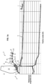
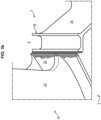
- the coupling is moreover all the greater as the zone within which the damping device 4 is arranged presents the highest relative tangential displacements for the mode with zero phase shift considered, as illustrated in figure 3a And 3b .
- these relative displacements are of the order of a few millimeters.
- the damping device 4 also advantageously retains efficiency on the vibratory modes of the fan blades 20 2 with non-zero phase shift.
- the assembly 1 comprises a fixing lug 8 connected on the one hand to the damping device 4, and on the other hand to the connection between the fan 2 and the low pressure compressor 3, so as to ensure anti-rotation, as well as the axial and radial stopping of the damping device 4.
- a fixing lug 8 connected on the one hand to the damping device 4, and on the other hand to the connection between the fan 2 and the low pressure compressor 3, so as to ensure anti-rotation, as well as the axial and radial stopping of the damping device 4.
- the fixing lug 8 is fixed to the connection between fan 2 and low pressure compressor 3 at the level of the bolted connection 22 between disc 21 and shroud 32.
- the fixing lug 8 can also be interposed between two circumferentially adjacent damping devices 4, and fixed to the latter, for example by screwing.
- the fixing lug 8 can be fixed to the damping devices 4 by any other fixing means known to those skilled in the art.
- the assembly 1 can also comprise two fixing lugs 8, fixed on each side of the damping device 4, for example by screwing.
- the fixing lugs 8 can be fixed to the damping devices 4 by any other fixing means known to those skilled in the art.
- the assembly 1 can further comprise a second sacrificial plate 80 housed at the level of the external surface 81 of the fixing lug 8, the second plate 80 being configured to increase the tangential stiffness of the damper device 4.
- the second sacrificial plate 80 also has the same characteristics as the first sacrificial plate 40, in particular as regards the composition, the lubrication and the additional coatings.
- the damping device 4 comprises a first sacrificial plate 40 housed at the level of the first 41 and the second 42 bearing surface.
- This first plate 40 is configured to guarantee the support of the external radial surfaces 41, 42 of the damping device 4 on the fan 2 and the low pressure compressor 3. Indeed, the mechanical stresses in operation are such that slight tangential, axial movements and radials of the damping device 4 are to be expected. These movements are in particular due to the tangential beats to be damped, but also to the centrifugal loading of the assembly 1. It is necessary that these movements do not wear out the blades 20 or the ferrule 32, the coatings of which are relatively fragile.
- the first sacrificial plate 40 comprises an anti-wear material, for example of the Teflon type, a metal such as titanium, or any specific composite material known to those skilled in the art.
- the first sacrificial wafer 40 can be treated by dry lubrication, with a view to perpetuating the value of the coefficient of friction between damping device 4 and shroud 32 and/or platform 25 of blade 2.
- This material with lubricating properties is by example of MoS2 type.
- the first sacrificial wafer 40 has a “V” shape.
- the first sacrificial plate 40 can also comprise an additional coating 44, as visible on the figure 4b , 5a And 5b .
- a coating 44 is configured to reduce friction and/or wear of the engine parts between the first pad 40 and the rotor modules 2, 3.
- This coating 44 is for example of the viscoelastic type.
- Such a coating 44 then advantageously comprises a material having properties similar to those of a material such as those of the range having the trade name “SMACTANEO”, for example a material of the “ SMACTANE® 70” type.
- Another way of increasing the tangential stiffness of assembly 1 is to sufficiently prestress viscoelastic coating 44 so that the relative tangential displacement between blade 20 and shroud 32 is transformed into viscoelastic shearing of coating 44 alone.
- this coating 44 is of the dissipative and/or viscoelastic and/or damping type.
- the dissipative coating 44 then comprises a material chosen from among those having mechanical properties similar to those of vespel, Teflon or any other material with lubricating properties. More generally, the material has a coefficient of friction between 0.3 and 0.07.
- the tangential coupling damping can be adjusted by controlling the mass of the damping device 4, which influences the shear inertia.
- This control involves modifications to the mass of the damping device 4.
- This mass can be modified in all or part of the damping device 4, typically by making bores 45 to lighten, and/or by adding one or more inserts 46, for example metal, to weigh down.
- the combination of the second and the third embodiment makes it possible to adjust the contact forces between the damping device 4 and the fan 2 as well as the low-pressure compressor 3. Indeed, too high contact forces between the blade 20 of the fan 2 and the damping device 4 would limit the dissipation of vibrations in operation.
- the damping device 4 comprises two shoulders 47 on either side of a notch 48 provided at the level of the internal surface 49 of the damping device 4, the shoulders 47 being in abutment, according to the invention, against the stilt 27 , as seen on the figure 5a .
- the shoulders 470, 472 also extend on either side of the stilt 27 in a circumferential direction, downstream of the stilt 27.
- a first shoulder 470 extends along a first side 270 of the stilt 27, downstream of the stilt 27, and a second shoulder 472 extends along a second side 272 of the stilt 27, opposite the first side 270 of the stilt 27 in a circumferential direction, also downstream of the stilt 27.
- the internal support of the damping device 4 on the shroud 32 notably guarantees radial stability.
- the internal support of the damping device 4 on the stilt 27 notably guarantees circumferential stability.
- the elasticity of the first shoulder 470 and of the second shoulder 472 also contributes to the axial pre-holding of the damping device 4 during assembly and/or operation.
- the first shoulder 470 and the second shoulder 472 comprise polyurethane, which allows said shoulders 470, 472 to be deformed during assembly and/or in operation.
- the fixing lug 8 can then be connected to the damping device 4 at the level of the notch 48 separating the two shoulders 47.
- the notch 48 may comprise a third sacrificial plate 480 on which the leg of binding 8 bears, ensuring functions equivalent to those of the first sacrificial plate 40, and having the same characteristics, in particular as regards the composition, the lubrication and the additional coatings.
- first rotor module 2 is a fan
- second rotor module 3 is a low pressure compressor
- first rotor module 2 can also be a first compressor stage, high or low pressure, and the second rotor module 3 a second stage of said compressor, successive to the first compressor stage, upstream or downstream of the latter.
- first rotor module 2 is a first stage turbine, high or low pressure, and the second rotor module 3 a second stage of said turbine, successive to the first turbine stage, upstream or downstream of the latter.
Landscapes
- Engineering & Computer Science (AREA)
- Mechanical Engineering (AREA)
- General Engineering & Computer Science (AREA)
- Structures Of Non-Positive Displacement Pumps (AREA)
- Turbine Rotor Nozzle Sealing (AREA)
Claims (14)
- Anordnung (1) für eine Turbomaschine, bestehend aus :• einem ersten Rotormodul (2) mit einer Scheibe (21), die auf einer Längsachse (X-X) der Turbomaschine zentriert ist, einer ersten Schaufel (20), die am äußeren Umfang der Scheibe (21) montiert ist, von der sie sich erstreckt, wobei die erste Schaufel (20) ein Blatt (23), eine Plattform (25), eine Stelze (27) und einen Fuß (29) aufweist, der in eine Aufnahme (210) der Scheibe (21) eingelassen ist,• einem zweiten Rotormodul (3), das mit dem ersten Rotormodul (2) verbunden ist und umfasst:∘ eine zweite Schaufel (30), deren Länge geringer ist als die der ersten Schaufel (20), und∘ einen Ring (32) mit einer Umfangserweiterung (34), die sich in Richtung der Plattform (25) der ersten Schaufel (20) erstreckt, und• eine Dämpfungsvorrichtung (4) mit einer ersten radialen Außenfläche (41), die reibend an dem ersten Rotormodul (2) an einer Innenfläche (250) der Plattform (25) der ersten Schaufel (20) anliegt, sowie mit einer zweiten radialen Außenfläche (42), die reibend an dem zweiten Modul (3) anliegt, gegen die Umfangserstreckung (34) des Rings (32), so dass die Module (2, 3) gekoppelt werden, um ihre jeweiligen Vibrationsbewegungen im Betrieb zu dämpfen, wobei die Dämpfungsvorrichtung (4) außerdem zwei Schultern (47) auf beiden Seiten einer Aussparung (48) umfasst, die auf der Höhe einer Innenfläche (49) der Dämpfungsvorrichtung (4) ausgebildet ist, dadurch gekennzeichnet, dass die Schultern (47) an der Stelze (27) anliegen.
- Anordnung (1) nach Anspruch 1, wobei die Dämpfungsvorrichtung (4) eine erste Opferplatte (40) umfasst, das an der ersten (41) und der zweiten (42) radialen Außenfläche aufgenommen ist, wobei die erste Opferplatte (40) so konfiguriert ist, dass es die Auflage der radialen Außenflächen (41, 42) gewährleistet.
- Anordnung (1) nach Anspruch 2, wobei die erste Opferplatte (40) eine Beschichtung (44) umfasst, die so konfiguriert ist, dass sie die Reibung zwischen der ersten Opferplatte (40) und den Rotormodulen (2, 3) verringert.
- Anordnung (1) nach Anspruch 2, wobei die erste Opferplatte (40) eine Beschichtung (44) vom viskoelastischen Typ umfasst.
- Anordnung (1) nach einem der Ansprüche 1 bis 4, wobei die Dämpfungsvorrichtung (4) Bohrungen (45) umfasst, die so gestaltet sind, dass sie die Masse der Dämpfungsvorrichtung (4) verringern.
- Anordnung (1) nach einem der Ansprüche 1 bis 5, wobei die Dämpfungsvorrichtung (4) Einsätze (46), z. B. metallischer Art, umfasst, die so gestaltet sind, dass sie die Dämpfungsvorrichtung (4) beschweren.
- Anordnung (1) nach einem der Ansprüche 1 bis 6, bei der die Schultern (47) zusätzlich an der Hülse (32) anliegen.
- Anordnung (1) nach einem der Ansprüche 1 bis 7, wobei sich die Schultern (47) auf beiden Seiten der Stelze (27) in einer Umfangsrichtung erstrecken.
- Anordnung (1) nach einem der Ansprüche 1 bis 8, die außerdem eine Befestigungslasche (8) umfasst, die einerseits mit der Dämpfungsvorrichtung (4) und andererseits mit der Verbindung zwischen dem ersten (2) und dem zweiten Rotormodul (3) verbunden ist, so dass die Rotationsverhinderung sowie die axiale und radiale Arretierung der Dämpfungsvorrichtung (4) gewährleistet sind.
- Anordnung (1) nach Anspruch 9, wobei die Befestigungslasche (8) ein zweites Opferplättchen (80) umfasst, das an einer Außenfläche (81) der Befestigungslasche (8) aufgenommen ist, wobei das zweite Opferplättchen (80) so konfiguriert ist, dass es die Tangentialsteifigkeit der Dämpfungsvorrichtung (4) erhöht.
- Anordnung (1) nach einem der Ansprüche 9 oder 10, wobei die Befestigungslasche (8) an der Aussparung (48) mit der Dämpfungsvorrichtung (4) verbunden ist.
- Anordnung (1) nach Anspruch 11, wobei die Aussparung (48) ein drittes Opferplättchen (480) umfasst, an dem die Befestigungslasche (8) anliegt.
- Anordnung (1) nach einem der Ansprüche 1 bis 12, wobei das erste Modul (2) ein Gebläse ist und das zweite Modul (3) ein Niederdruckkompressor ist.
- Turbomaschine mit einer Anordnung (1) nach einem der Ansprüche 1 bis 13.
Priority Applications (1)
| Application Number | Priority Date | Filing Date | Title |
|---|---|---|---|
| EP23181825.3A EP4253763B1 (de) | 2017-12-14 | 2018-12-14 | Dämpfungsvorrichtung |
Applications Claiming Priority (2)
| Application Number | Priority Date | Filing Date | Title |
|---|---|---|---|
| FR1762170A FR3075282B1 (fr) | 2017-12-14 | 2017-12-14 | Dispositif amortisseur |
| PCT/FR2018/053302 WO2019115977A1 (fr) | 2017-12-14 | 2018-12-14 | Dispositif amortisseur |
Related Child Applications (1)
| Application Number | Title | Priority Date | Filing Date |
|---|---|---|---|
| EP23181825.3A Division EP4253763B1 (de) | 2017-12-14 | 2018-12-14 | Dämpfungsvorrichtung |
Publications (2)
| Publication Number | Publication Date |
|---|---|
| EP3724455A1 EP3724455A1 (de) | 2020-10-21 |
| EP3724455B1 true EP3724455B1 (de) | 2023-06-28 |
Family
ID=61224116
Family Applications (2)
| Application Number | Title | Priority Date | Filing Date |
|---|---|---|---|
| EP18836279.2A Active EP3724455B1 (de) | 2017-12-14 | 2018-12-14 | Dämpfungsvorrichtung |
| EP23181825.3A Active EP4253763B1 (de) | 2017-12-14 | 2018-12-14 | Dämpfungsvorrichtung |
Family Applications After (1)
| Application Number | Title | Priority Date | Filing Date |
|---|---|---|---|
| EP23181825.3A Active EP4253763B1 (de) | 2017-12-14 | 2018-12-14 | Dämpfungsvorrichtung |
Country Status (5)
| Country | Link |
|---|---|
| US (1) | US11346233B2 (de) |
| EP (2) | EP3724455B1 (de) |
| CN (1) | CN111630249B (de) |
| FR (1) | FR3075282B1 (de) |
| WO (1) | WO2019115977A1 (de) |
Families Citing this family (5)
| Publication number | Priority date | Publication date | Assignee | Title |
|---|---|---|---|---|
| FR3075284B1 (fr) * | 2017-12-18 | 2020-09-04 | Safran Aircraft Engines | Dispositif amortisseur |
| CN111615584B (zh) * | 2017-12-18 | 2022-08-16 | 赛峰飞机发动机公司 | 阻尼装置 |
| FR3096732B1 (fr) * | 2019-05-29 | 2024-09-13 | Safran Aircraft Engines | Ensemble pour turbomachine |
| FR3099213B1 (fr) * | 2019-07-23 | 2021-07-16 | Safran Aircraft Engines | Rotor de soufflante pour une turbomachine d’aeronef |
| US11333026B2 (en) * | 2020-05-26 | 2022-05-17 | General Electric Company | Vibration-damping system for turbomachine blade(s) on spacer adjacent blade stage |
Citations (3)
| Publication number | Priority date | Publication date | Assignee | Title |
|---|---|---|---|---|
| EP1985810A1 (de) * | 2007-04-27 | 2008-10-29 | Snecma | Stoßdämpfer für Laufradschaufeln eines Turbotriebwerks |
| FR2923557A1 (fr) * | 2007-11-12 | 2009-05-15 | Snecma Sa | Ensemble d'une aube de soufflante et de son amortisseur, amortisseur d'aube de soufflante et methode de calibrage de l'amortisseur |
| CN204941612U (zh) * | 2015-09-16 | 2016-01-06 | 中国航空工业集团公司沈阳发动机设计研究所 | 一种可压缩阻尼块 |
Family Cites Families (11)
| Publication number | Priority date | Publication date | Assignee | Title |
|---|---|---|---|---|
| FR2345605A1 (fr) * | 1976-03-25 | 1977-10-21 | Snecma | Dispositif de retenue pour aubes de soufflantes |
| FR2585069B1 (fr) * | 1985-07-16 | 1989-06-09 | Snecma | Dispositif de limitation du debattement angulaire d'aubes montees sur un disque de rotor de turbomachine |
| US5205713A (en) * | 1991-04-29 | 1993-04-27 | General Electric Company | Fan blade damper |
| US5573375A (en) * | 1994-12-14 | 1996-11-12 | United Technologies Corporation | Turbine engine rotor blade platform sealing and vibration damping device |
| US5820346A (en) * | 1996-12-17 | 1998-10-13 | General Electric Company | Blade damper for a turbine engine |
| US8371816B2 (en) * | 2009-07-31 | 2013-02-12 | General Electric Company | Rotor blades for turbine engines |
| FR2949142B1 (fr) * | 2009-08-11 | 2011-10-14 | Snecma | Cale amortisseuse de vibrations pour aube de soufflante |
| US8540488B2 (en) * | 2009-12-14 | 2013-09-24 | Siemens Energy, Inc. | Turbine blade damping device with controlled loading |
| RU2461717C1 (ru) * | 2011-03-17 | 2012-09-20 | Федеральное государственное унитарное предприятие "Центральный институт авиационного моторостроения имени П.И. Баранова" | Устройство демпфирования колебаний широкохордных рабочих лопаток вентиляторов с большой конусностью втулки и вентилятор газотурбинного двигателя |
| FR2988427B1 (fr) | 2012-03-20 | 2017-07-21 | Snecma | Plate-forme inter-aubes |
| US10927683B2 (en) * | 2017-12-14 | 2021-02-23 | Safran Aircraft Engines | Damping device |
-
2017
- 2017-12-14 FR FR1762170A patent/FR3075282B1/fr active Active
-
2018
- 2018-12-14 CN CN201880086692.2A patent/CN111630249B/zh active Active
- 2018-12-14 WO PCT/FR2018/053302 patent/WO2019115977A1/fr not_active Ceased
- 2018-12-14 EP EP18836279.2A patent/EP3724455B1/de active Active
- 2018-12-14 EP EP23181825.3A patent/EP4253763B1/de active Active
- 2018-12-14 US US16/954,007 patent/US11346233B2/en active Active
Patent Citations (3)
| Publication number | Priority date | Publication date | Assignee | Title |
|---|---|---|---|---|
| EP1985810A1 (de) * | 2007-04-27 | 2008-10-29 | Snecma | Stoßdämpfer für Laufradschaufeln eines Turbotriebwerks |
| FR2923557A1 (fr) * | 2007-11-12 | 2009-05-15 | Snecma Sa | Ensemble d'une aube de soufflante et de son amortisseur, amortisseur d'aube de soufflante et methode de calibrage de l'amortisseur |
| CN204941612U (zh) * | 2015-09-16 | 2016-01-06 | 中国航空工业集团公司沈阳发动机设计研究所 | 一种可压缩阻尼块 |
Also Published As
| Publication number | Publication date |
|---|---|
| US20210079794A1 (en) | 2021-03-18 |
| EP4253763A2 (de) | 2023-10-04 |
| US11346233B2 (en) | 2022-05-31 |
| EP4253763A3 (de) | 2023-12-27 |
| CN111630249A (zh) | 2020-09-04 |
| CN111630249B (zh) | 2022-05-24 |
| WO2019115977A1 (fr) | 2019-06-20 |
| EP4253763B1 (de) | 2026-02-04 |
| FR3075282B1 (fr) | 2021-01-08 |
| EP3724455A1 (de) | 2020-10-21 |
| FR3075282A1 (fr) | 2019-06-21 |
Similar Documents
| Publication | Publication Date | Title |
|---|---|---|
| EP4253763B1 (de) | Dämpfungsvorrichtung | |
| EP0214875B1 (de) | Dämpfungselement zur Begrenzung der Auslenkung von Rotorschaufeln einer Turbomaschine | |
| EP1916431B1 (de) | Lageranordnung einer Drehwelle und mit einer solchen Anordnung ausgestatteter Turboreaktor | |
| FR3075284A1 (fr) | Dispositif amortisseur | |
| WO2022157443A1 (fr) | Ensemble comportant une turbomachine d'aeronef et son pylone d'accrochage | |
| FR2931871A1 (fr) | Rotor de soufflante pour une turbomachine. | |
| EP3728794B1 (de) | Dämpfervorrichtung | |
| FR3102205A1 (fr) | Rotor de turbomachine à masselotte | |
| FR3075253B1 (fr) | Dispositif amortisseur | |
| EP3976926B1 (de) | Turbomaschinenanordnung mit dämpfer | |
| EP3976929B1 (de) | Anordnung für eine turbomaschine | |
| FR3075283B1 (fr) | Dispositif amortisseur | |
| EP3976928B1 (de) | Anordnung für turbomaschine und turbomaschine | |
| FR3075254B1 (fr) | Dispositif amortisseur | |
| FR3096730A1 (fr) | Ensemble pour turbomachine | |
| FR3123696A1 (fr) | Système de commande du calage angulaire d’une aube d’helice pour une turbomachine d’aeronef | |
| FR3096732A1 (fr) | Ensemble pour turbomachine | |
| FR3096733A1 (fr) | Ensemble pour turbomachine | |
| EP4010566B1 (de) | Turbinentriebwerksverdichter für flugzeuge mit einer vorrichtung zum fixieren eines halteringes | |
| FR3042215B1 (fr) | Structure pour turbomachine comportant des moyens de retention axiale de bague exterieure de palier de roulement | |
| WO2026033179A1 (fr) | Aube a calage variable pour une turbomachine | |
| FR3166173A1 (fr) | Ensemble d’un carter de soufflante d’une turbomachine et d’une manche à air de nacelle | |
| WO2025061774A1 (fr) | Carter de compresseur basse pression d'une turbomachine d'aéronef | |
| FR3057907A1 (fr) | Ensemble a effet anti-usure pour turboreacteur |
Legal Events
| Date | Code | Title | Description |
|---|---|---|---|
| STAA | Information on the status of an ep patent application or granted ep patent |
Free format text: STATUS: UNKNOWN |
|
| STAA | Information on the status of an ep patent application or granted ep patent |
Free format text: STATUS: THE INTERNATIONAL PUBLICATION HAS BEEN MADE |
|
| PUAI | Public reference made under article 153(3) epc to a published international application that has entered the european phase |
Free format text: ORIGINAL CODE: 0009012 |
|
| STAA | Information on the status of an ep patent application or granted ep patent |
Free format text: STATUS: REQUEST FOR EXAMINATION WAS MADE |
|
| 17P | Request for examination filed |
Effective date: 20200713 |
|
| AK | Designated contracting states |
Kind code of ref document: A1 Designated state(s): AL AT BE BG CH CY CZ DE DK EE ES FI FR GB GR HR HU IE IS IT LI LT LU LV MC MK MT NL NO PL PT RO RS SE SI SK SM TR |
|
| AX | Request for extension of the european patent |
Extension state: BA ME |
|
| DAV | Request for validation of the european patent (deleted) | ||
| DAX | Request for extension of the european patent (deleted) | ||
| STAA | Information on the status of an ep patent application or granted ep patent |
Free format text: STATUS: EXAMINATION IS IN PROGRESS |
|
| 17Q | First examination report despatched |
Effective date: 20211221 |
|
| GRAP | Despatch of communication of intention to grant a patent |
Free format text: ORIGINAL CODE: EPIDOSNIGR1 |
|
| STAA | Information on the status of an ep patent application or granted ep patent |
Free format text: STATUS: GRANT OF PATENT IS INTENDED |
|
| INTG | Intention to grant announced |
Effective date: 20230322 |
|
| GRAS | Grant fee paid |
Free format text: ORIGINAL CODE: EPIDOSNIGR3 |
|
| GRAA | (expected) grant |
Free format text: ORIGINAL CODE: 0009210 |
|
| STAA | Information on the status of an ep patent application or granted ep patent |
Free format text: STATUS: THE PATENT HAS BEEN GRANTED |
|
| AK | Designated contracting states |
Kind code of ref document: B1 Designated state(s): AL AT BE BG CH CY CZ DE DK EE ES FI FR GB GR HR HU IE IS IT LI LT LU LV MC MK MT NL NO PL PT RO RS SE SI SK SM TR |
|
| REG | Reference to a national code |
Ref country code: CH Ref legal event code: EP |
|
| REG | Reference to a national code |
Ref country code: AT Ref legal event code: REF Ref document number: 1582848 Country of ref document: AT Kind code of ref document: T Effective date: 20230715 |
|
| REG | Reference to a national code |
Ref country code: IE Ref legal event code: FG4D Free format text: LANGUAGE OF EP DOCUMENT: FRENCH |
|
| REG | Reference to a national code |
Ref country code: DE Ref legal event code: R096 Ref document number: 602018052564 Country of ref document: DE |
|
| REG | Reference to a national code |
Ref country code: LT Ref legal event code: MG9D |
|
| PG25 | Lapsed in a contracting state [announced via postgrant information from national office to epo] |
Ref country code: SE Free format text: LAPSE BECAUSE OF FAILURE TO SUBMIT A TRANSLATION OF THE DESCRIPTION OR TO PAY THE FEE WITHIN THE PRESCRIBED TIME-LIMIT Effective date: 20230628 Ref country code: NO Free format text: LAPSE BECAUSE OF FAILURE TO SUBMIT A TRANSLATION OF THE DESCRIPTION OR TO PAY THE FEE WITHIN THE PRESCRIBED TIME-LIMIT Effective date: 20230928 |
|
| REG | Reference to a national code |
Ref country code: NL Ref legal event code: MP Effective date: 20230628 |
|
| REG | Reference to a national code |
Ref country code: AT Ref legal event code: MK05 Ref document number: 1582848 Country of ref document: AT Kind code of ref document: T Effective date: 20230628 |
|
| PG25 | Lapsed in a contracting state [announced via postgrant information from national office to epo] |
Ref country code: RS Free format text: LAPSE BECAUSE OF FAILURE TO SUBMIT A TRANSLATION OF THE DESCRIPTION OR TO PAY THE FEE WITHIN THE PRESCRIBED TIME-LIMIT Effective date: 20230628 Ref country code: NL Free format text: LAPSE BECAUSE OF FAILURE TO SUBMIT A TRANSLATION OF THE DESCRIPTION OR TO PAY THE FEE WITHIN THE PRESCRIBED TIME-LIMIT Effective date: 20230628 Ref country code: LV Free format text: LAPSE BECAUSE OF FAILURE TO SUBMIT A TRANSLATION OF THE DESCRIPTION OR TO PAY THE FEE WITHIN THE PRESCRIBED TIME-LIMIT Effective date: 20230628 Ref country code: LT Free format text: LAPSE BECAUSE OF FAILURE TO SUBMIT A TRANSLATION OF THE DESCRIPTION OR TO PAY THE FEE WITHIN THE PRESCRIBED TIME-LIMIT Effective date: 20230628 Ref country code: HR Free format text: LAPSE BECAUSE OF FAILURE TO SUBMIT A TRANSLATION OF THE DESCRIPTION OR TO PAY THE FEE WITHIN THE PRESCRIBED TIME-LIMIT Effective date: 20230628 Ref country code: GR Free format text: LAPSE BECAUSE OF FAILURE TO SUBMIT A TRANSLATION OF THE DESCRIPTION OR TO PAY THE FEE WITHIN THE PRESCRIBED TIME-LIMIT Effective date: 20230929 |
|
| PG25 | Lapsed in a contracting state [announced via postgrant information from national office to epo] |
Ref country code: FI Free format text: LAPSE BECAUSE OF FAILURE TO SUBMIT A TRANSLATION OF THE DESCRIPTION OR TO PAY THE FEE WITHIN THE PRESCRIBED TIME-LIMIT Effective date: 20230628 |
|
| PG25 | Lapsed in a contracting state [announced via postgrant information from national office to epo] |
Ref country code: SK Free format text: LAPSE BECAUSE OF FAILURE TO SUBMIT A TRANSLATION OF THE DESCRIPTION OR TO PAY THE FEE WITHIN THE PRESCRIBED TIME-LIMIT Effective date: 20230628 |
|
| PG25 | Lapsed in a contracting state [announced via postgrant information from national office to epo] |
Ref country code: ES Free format text: LAPSE BECAUSE OF FAILURE TO SUBMIT A TRANSLATION OF THE DESCRIPTION OR TO PAY THE FEE WITHIN THE PRESCRIBED TIME-LIMIT Effective date: 20230628 |
|
| PG25 | Lapsed in a contracting state [announced via postgrant information from national office to epo] |
Ref country code: IS Free format text: LAPSE BECAUSE OF FAILURE TO SUBMIT A TRANSLATION OF THE DESCRIPTION OR TO PAY THE FEE WITHIN THE PRESCRIBED TIME-LIMIT Effective date: 20231028 |
|
| PG25 | Lapsed in a contracting state [announced via postgrant information from national office to epo] |
Ref country code: SM Free format text: LAPSE BECAUSE OF FAILURE TO SUBMIT A TRANSLATION OF THE DESCRIPTION OR TO PAY THE FEE WITHIN THE PRESCRIBED TIME-LIMIT Effective date: 20230628 Ref country code: SK Free format text: LAPSE BECAUSE OF FAILURE TO SUBMIT A TRANSLATION OF THE DESCRIPTION OR TO PAY THE FEE WITHIN THE PRESCRIBED TIME-LIMIT Effective date: 20230628 Ref country code: RO Free format text: LAPSE BECAUSE OF FAILURE TO SUBMIT A TRANSLATION OF THE DESCRIPTION OR TO PAY THE FEE WITHIN THE PRESCRIBED TIME-LIMIT Effective date: 20230628 Ref country code: PT Free format text: LAPSE BECAUSE OF FAILURE TO SUBMIT A TRANSLATION OF THE DESCRIPTION OR TO PAY THE FEE WITHIN THE PRESCRIBED TIME-LIMIT Effective date: 20231030 Ref country code: IS Free format text: LAPSE BECAUSE OF FAILURE TO SUBMIT A TRANSLATION OF THE DESCRIPTION OR TO PAY THE FEE WITHIN THE PRESCRIBED TIME-LIMIT Effective date: 20231028 Ref country code: ES Free format text: LAPSE BECAUSE OF FAILURE TO SUBMIT A TRANSLATION OF THE DESCRIPTION OR TO PAY THE FEE WITHIN THE PRESCRIBED TIME-LIMIT Effective date: 20230628 Ref country code: EE Free format text: LAPSE BECAUSE OF FAILURE TO SUBMIT A TRANSLATION OF THE DESCRIPTION OR TO PAY THE FEE WITHIN THE PRESCRIBED TIME-LIMIT Effective date: 20230628 Ref country code: CZ Free format text: LAPSE BECAUSE OF FAILURE TO SUBMIT A TRANSLATION OF THE DESCRIPTION OR TO PAY THE FEE WITHIN THE PRESCRIBED TIME-LIMIT Effective date: 20230628 Ref country code: AT Free format text: LAPSE BECAUSE OF FAILURE TO SUBMIT A TRANSLATION OF THE DESCRIPTION OR TO PAY THE FEE WITHIN THE PRESCRIBED TIME-LIMIT Effective date: 20230628 |
|
| PG25 | Lapsed in a contracting state [announced via postgrant information from national office to epo] |
Ref country code: PL Free format text: LAPSE BECAUSE OF FAILURE TO SUBMIT A TRANSLATION OF THE DESCRIPTION OR TO PAY THE FEE WITHIN THE PRESCRIBED TIME-LIMIT Effective date: 20230628 |
|
| REG | Reference to a national code |
Ref country code: DE Ref legal event code: R097 Ref document number: 602018052564 Country of ref document: DE |
|
| PG25 | Lapsed in a contracting state [announced via postgrant information from national office to epo] |
Ref country code: DK Free format text: LAPSE BECAUSE OF FAILURE TO SUBMIT A TRANSLATION OF THE DESCRIPTION OR TO PAY THE FEE WITHIN THE PRESCRIBED TIME-LIMIT Effective date: 20230628 |
|
| PLBE | No opposition filed within time limit |
Free format text: ORIGINAL CODE: 0009261 |
|
| STAA | Information on the status of an ep patent application or granted ep patent |
Free format text: STATUS: NO OPPOSITION FILED WITHIN TIME LIMIT |
|
| PG25 | Lapsed in a contracting state [announced via postgrant information from national office to epo] |
Ref country code: IT Free format text: LAPSE BECAUSE OF FAILURE TO SUBMIT A TRANSLATION OF THE DESCRIPTION OR TO PAY THE FEE WITHIN THE PRESCRIBED TIME-LIMIT Effective date: 20230628 |
|
| 26N | No opposition filed |
Effective date: 20240402 |
|
| PG25 | Lapsed in a contracting state [announced via postgrant information from national office to epo] |
Ref country code: SI Free format text: LAPSE BECAUSE OF FAILURE TO SUBMIT A TRANSLATION OF THE DESCRIPTION OR TO PAY THE FEE WITHIN THE PRESCRIBED TIME-LIMIT Effective date: 20230628 |
|
| REG | Reference to a national code |
Ref country code: CH Ref legal event code: PL |
|
| PG25 | Lapsed in a contracting state [announced via postgrant information from national office to epo] |
Ref country code: LU Free format text: LAPSE BECAUSE OF NON-PAYMENT OF DUE FEES Effective date: 20231214 |
|
| PG25 | Lapsed in a contracting state [announced via postgrant information from national office to epo] |
Ref country code: MC Free format text: LAPSE BECAUSE OF FAILURE TO SUBMIT A TRANSLATION OF THE DESCRIPTION OR TO PAY THE FEE WITHIN THE PRESCRIBED TIME-LIMIT Effective date: 20230628 |
|
| REG | Reference to a national code |
Ref country code: BE Ref legal event code: MM Effective date: 20231231 |
|
| PG25 | Lapsed in a contracting state [announced via postgrant information from national office to epo] |
Ref country code: MC Free format text: LAPSE BECAUSE OF FAILURE TO SUBMIT A TRANSLATION OF THE DESCRIPTION OR TO PAY THE FEE WITHIN THE PRESCRIBED TIME-LIMIT Effective date: 20230628 Ref country code: LU Free format text: LAPSE BECAUSE OF NON-PAYMENT OF DUE FEES Effective date: 20231214 |
|
| REG | Reference to a national code |
Ref country code: IE Ref legal event code: MM4A |
|
| PG25 | Lapsed in a contracting state [announced via postgrant information from national office to epo] |
Ref country code: IE Free format text: LAPSE BECAUSE OF NON-PAYMENT OF DUE FEES Effective date: 20231214 |
|
| PG25 | Lapsed in a contracting state [announced via postgrant information from national office to epo] |
Ref country code: BE Free format text: LAPSE BECAUSE OF NON-PAYMENT OF DUE FEES Effective date: 20231231 |
|
| PG25 | Lapsed in a contracting state [announced via postgrant information from national office to epo] |
Ref country code: CH Free format text: LAPSE BECAUSE OF NON-PAYMENT OF DUE FEES Effective date: 20231231 |
|
| PG25 | Lapsed in a contracting state [announced via postgrant information from national office to epo] |
Ref country code: IE Free format text: LAPSE BECAUSE OF NON-PAYMENT OF DUE FEES Effective date: 20231214 Ref country code: CH Free format text: LAPSE BECAUSE OF NON-PAYMENT OF DUE FEES Effective date: 20231231 Ref country code: BE Free format text: LAPSE BECAUSE OF NON-PAYMENT OF DUE FEES Effective date: 20231231 |
|
| PG25 | Lapsed in a contracting state [announced via postgrant information from national office to epo] |
Ref country code: BG Free format text: LAPSE BECAUSE OF FAILURE TO SUBMIT A TRANSLATION OF THE DESCRIPTION OR TO PAY THE FEE WITHIN THE PRESCRIBED TIME-LIMIT Effective date: 20230628 |
|
| PG25 | Lapsed in a contracting state [announced via postgrant information from national office to epo] |
Ref country code: BG Free format text: LAPSE BECAUSE OF FAILURE TO SUBMIT A TRANSLATION OF THE DESCRIPTION OR TO PAY THE FEE WITHIN THE PRESCRIBED TIME-LIMIT Effective date: 20230628 |
|
| PG25 | Lapsed in a contracting state [announced via postgrant information from national office to epo] |
Ref country code: CY Free format text: LAPSE BECAUSE OF FAILURE TO SUBMIT A TRANSLATION OF THE DESCRIPTION OR TO PAY THE FEE WITHIN THE PRESCRIBED TIME-LIMIT; INVALID AB INITIO Effective date: 20181214 |
|
| PG25 | Lapsed in a contracting state [announced via postgrant information from national office to epo] |
Ref country code: HU Free format text: LAPSE BECAUSE OF FAILURE TO SUBMIT A TRANSLATION OF THE DESCRIPTION OR TO PAY THE FEE WITHIN THE PRESCRIBED TIME-LIMIT; INVALID AB INITIO Effective date: 20181214 |
|
| PG25 | Lapsed in a contracting state [announced via postgrant information from national office to epo] |
Ref country code: TR Free format text: LAPSE BECAUSE OF FAILURE TO SUBMIT A TRANSLATION OF THE DESCRIPTION OR TO PAY THE FEE WITHIN THE PRESCRIBED TIME-LIMIT Effective date: 20230628 |
|
| PGFP | Annual fee paid to national office [announced via postgrant information from national office to epo] |
Ref country code: GB Payment date: 20251229 Year of fee payment: 8 |
|
| PGFP | Annual fee paid to national office [announced via postgrant information from national office to epo] |
Ref country code: FR Payment date: 20251222 Year of fee payment: 8 |
|
| PGFP | Annual fee paid to national office [announced via postgrant information from national office to epo] |
Ref country code: DE Payment date: 20251222 Year of fee payment: 8 |