EP3724461B1 - Arbre à cames rapportées et son procédé de fabrication - Google Patents
Arbre à cames rapportées et son procédé de fabrication Download PDFInfo
- Publication number
- EP3724461B1 EP3724461B1 EP18822318.4A EP18822318A EP3724461B1 EP 3724461 B1 EP3724461 B1 EP 3724461B1 EP 18822318 A EP18822318 A EP 18822318A EP 3724461 B1 EP3724461 B1 EP 3724461B1
- Authority
- EP
- European Patent Office
- Prior art keywords
- hub
- base shaft
- tooth
- locking part
- toothing
- Prior art date
- Legal status (The legal status is an assumption and is not a legal conclusion. Google has not performed a legal analysis and makes no representation as to the accuracy of the status listed.)
- Active
Links
Images


Classifications
-
- F—MECHANICAL ENGINEERING; LIGHTING; HEATING; WEAPONS; BLASTING
- F01—MACHINES OR ENGINES IN GENERAL; ENGINE PLANTS IN GENERAL; STEAM ENGINES
- F01L—CYCLICALLY OPERATING VALVES FOR MACHINES OR ENGINES
- F01L1/00—Valve-gear or valve arrangements, e.g. lift-valve gear
- F01L1/02—Valve drive
- F01L1/04—Valve drive by means of cams, camshafts, cam discs, eccentrics or the like
- F01L1/047—Camshafts
-
- F—MECHANICAL ENGINEERING; LIGHTING; HEATING; WEAPONS; BLASTING
- F16—ENGINEERING ELEMENTS AND UNITS; GENERAL MEASURES FOR PRODUCING AND MAINTAINING EFFECTIVE FUNCTIONING OF MACHINES OR INSTALLATIONS; THERMAL INSULATION IN GENERAL
- F16H—GEARING
- F16H53/00—Cams or cam-followers, e.g. rollers for gearing mechanisms
- F16H53/02—Single-track cams for single-revolution cycles; Camshafts with such cams
- F16H53/025—Single-track cams for single-revolution cycles; Camshafts with such cams characterised by their construction, e.g. assembling or manufacturing features
-
- B—PERFORMING OPERATIONS; TRANSPORTING
- B23—MACHINE TOOLS; METAL-WORKING NOT OTHERWISE PROVIDED FOR
- B23P—METAL-WORKING NOT OTHERWISE PROVIDED FOR; COMBINED OPERATIONS; UNIVERSAL MACHINE TOOLS
- B23P15/00—Making specific metal objects by operations not covered by a single other subclass or a group in this subclass
-
- B—PERFORMING OPERATIONS; TRANSPORTING
- B23—MACHINE TOOLS; METAL-WORKING NOT OTHERWISE PROVIDED FOR
- B23P—METAL-WORKING NOT OTHERWISE PROVIDED FOR; COMBINED OPERATIONS; UNIVERSAL MACHINE TOOLS
- B23P2700/00—Indexing scheme relating to the articles being treated, e.g. manufactured, repaired, assembled, connected or other operations covered in the subgroups
- B23P2700/02—Camshafts
-
- F—MECHANICAL ENGINEERING; LIGHTING; HEATING; WEAPONS; BLASTING
- F01—MACHINES OR ENGINES IN GENERAL; ENGINE PLANTS IN GENERAL; STEAM ENGINES
- F01L—CYCLICALLY OPERATING VALVES FOR MACHINES OR ENGINES
- F01L1/00—Valve-gear or valve arrangements, e.g. lift-valve gear
- F01L1/02—Valve drive
- F01L1/04—Valve drive by means of cams, camshafts, cam discs, eccentrics or the like
- F01L1/047—Camshafts
- F01L2001/0471—Assembled camshafts
-
- F—MECHANICAL ENGINEERING; LIGHTING; HEATING; WEAPONS; BLASTING
- F01—MACHINES OR ENGINES IN GENERAL; ENGINE PLANTS IN GENERAL; STEAM ENGINES
- F01L—CYCLICALLY OPERATING VALVES FOR MACHINES OR ENGINES
- F01L2303/00—Manufacturing of components used in valve arrangements
Definitions
- the present invention relates to an assembled camshaft and a method for producing an assembled camshaft, wherein the camshaft is designed as a sliding camshaft and has axially fixed functional elements, such as cams, as well as axially displaceable cams on the base shaft.
- a built camshaft for installation in an internal combustion engine is available from the DE 10 2011 103 544 A1 known.
- the base shaft has an external toothing, by means of which sliding cam units are guided axially on the base shaft and are connected to the base shaft in a rotationally fixed manner.
- Bearing rings attached to the external toothing serve to support and guide the camshaft in the internal combustion engine.
- the bearing elements are joined by means of a press fit, in particular thermally.
- it is considered disadvantageous here that the bearing rings are pushed over the external toothing with an overlap and that large temperature differences act on the camshaft or the components during thermal joining.
- a built camshaft in which a hub can be moved on short sections of the base shaft is made by the US 2006/064872 revealed.
- a method for producing a camshaft and a camshaft produced using this method are to be provided in which no temperature is introduced into the axially fixed or axially non-displaceable hub. Furthermore, a method for producing a camshaft is to be provided in which the axially non-displaceable hub is only pushed over a toothing of the base shaft over short sections.
- the assembled camshaft for an internal combustion engine comprises a base shaft with an external toothing extending at least partially axially along the base shaft, and at least one hub with an internal toothing which correlates with the external toothing of the base shaft such that the hub is connected to the base shaft in a rotationally fixed and axially immovable manner, wherein the external toothing has at least one form-fitting part area or frictional part area extending at least partially axially along the base shaft in order to arrange the hub at least in a form-fitting or frictional manner. Furthermore, the form-fitting part area or the frictional part area is followed by at least one alignment area extending at least partially axially along the base shaft.
- the external toothing of at least the form-locking part area or the frictional part area has at least two tooth spaces with at least two mutually different widths and the internal toothing of the hub has at least one tooth which has a width that correlates with one of the different width tooth spaces of the base shaft, wherein the combination of the at least one tooth of the internal toothing of the hub with the first tooth space of the external toothing of the base shaft forms a sliding fit.
- At least the frictional connection of the hub with the base shaft for axially fixing the hub is formed by a combination of at least the second tooth space of the base shaft, which has a second width, and the at least one non-correlating first tooth of the internal toothing, which has a first width. Press connection.
- An external toothing is advantageously formed on the base shaft, thus creating the possibility of guiding various hubs axially along the base shaft and connecting them to it in a rotationally fixed manner, as is the case with sliding cam systems, for example.
- the toothing of the base shaft provides several positive locking elements for forming a positive locking connection.
- no positive locking is formed between the base shaft and the hub with its internal toothing in the alignment area, whereby the hub can be rotated or twisted into a desired angular position relative to the base shaft or its external toothing.
- the alignment area extends over the entire circumference of the base shaft, but at least over a partial circumference area, in order to enable the desired angular alignment of the hub relative to the external toothing or the base shaft.
- the alignment area can be formed, for example, by grinding or milling the external toothing. It is also possible that no external toothing is formed on the base shaft in the alignment area. It is advantageous that when the at least one tooth of the internal toothing of the hub, which has a defined width, is combined with the at least one first tooth gap of the external toothing of the base shaft, which has a first width, a sliding fit is formed between them. This advantageously allows the hub to be moved over the external toothing without damaging the external toothing.
- the undamaged external toothing can be used to connect other components in a rotationally fixed manner or for axial guidance during movement.
- the combination of the at least one tooth of the internal toothing and the second tooth gap of the external toothing, which has a second width, is used to axially fix the hub on the base shaft, whereby the tip circle and/or the root circle of the external toothing are not damaged when the hub is pushed over.
- the size ratios of the respective widths of the inter-tooth spaces or the teeth of the base shaft to each other are preferably designed as explained below.
- the first tooth or inter-tooth space is wider than the second tooth or inter-tooth space.
- the width at half the tooth height can serve as a basis for the analysis, for example. The same reference basis applies vice versa for the internal gearing. the hub.
- the corresponding size relationships of the other relevant tooth widths or tooth spaces correspond to the same scheme.
- the hub which is to be fixed axially immovably, can be, for example, a sensor wheel, a cam for actuating valves of the internal combustion engine or a pump cam for actuating a fuel pump or a vacuum pump.
- the hub is designed as a built-in multiple cam.
- the alignment area for the hub with its internal toothing does not form a form-locking part area or a frictional part area, so that the hub does not form a rotationally fixed connection with the base shaft in this area and can be rotated or twisted into its required angular position in order to then form at least the frictional connection with the base shaft in the corresponding angular position for axially fixing the hub due to a press connection formed between at least the second tooth space of the external toothing of the base shaft, which has a second width, and the tooth of the internal toothing of the hub, which has a width that does not correlate with the second width of the second tooth space.
- the external toothing of the base shaft can advantageously be designed as a multi-tooth profile, such as a splined shaft profile or a toothed hub profile with involute toothing.
- the external toothing can also be designed as a polygonal profile or a similar non-circular profile, which can ensure the rotationally fixed fixation of the hub on the base shaft, for example in the form of a frictional connection and/or positive connection for the transmission of a torque between the hub and the base shaft.
- the two tooth spaces of the base shaft with different widths are formed circumferentially in an alternating sequence 11.
- a large number of different tooth spaces are thus provided, which enables axial securing against larger forces.
- the tooth spaces of different widths of the external toothing are thus evenly distributed over the circumference, which results in even force introduction into the hub.
- the tooth of the internal toothing of the hub which has a first width, is distributed multiple times all the way around and matches the first and second tooth spaces.
- the advantage here is the uniform expansion or change in shape of the hub as a result of the press connection.
- the hub experiences an uneven introduction of torque or torque load over the circumference of the base shaft, as is the case with cams or pump cams, for example, it is also conceivable that the tooth spaces with their different widths are unevenly distributed over the circumference, then adapted to the effective torque curve, for example.
- the internal toothing of the hub has a second tooth with a second width, wherein the second tooth can form a sliding fit with the first tooth space and the second tooth space of the base shaft and the first and second teeth are formed circumferentially in an alternating sequence.
- the effective form-fitting partial area between the base shaft and the hub and thus the effective form-fitting and thus the transmittable torque are increased.
- the form-fitting part area and/or the force-fitting part area are divided by the alignment area into at least two axially spaced form-fitting part areas and/or force-fitting part areas.
- the hub can be pushed over areas of the external toothing through this arrangement or sequence of areas and the corresponding combination of the teeth and the correlating tooth spaces without forming a press connection and damaging the toothing. Only in the immediate vicinity of the end position, After the hub has been aligned at an angle in the alignment area, the press connection between the base shaft and the hub is formed. The hub only needs to be moved over a short area of the external gearing. The forces for assembly or the displacement path can therefore be reduced and the risk of damage to the external gearing can be minimized.
- the internal toothing of the hub with its axial extension is divided into at least two sub-areas.
- the toothing of the hub can be inserted into the at least two alignment areas.
- the internal toothing of the hub is therefore advantageously divided into several sub-areas that are axially spaced apart from one another.
- the individual alignment areas can therefore advantageously be made axially shorter than a single alignment area that is intended to accommodate the corresponding internal toothing of the hub during rotation or angular alignment.
- the external toothing used for other hubs for non-rotatable fixation and axial guidance on the base shaft only needs to be interrupted in these areas on smaller sections, which increases the transmittable torque or distributes the force distribution during torque transmission between shaft and hub.
- a base shaft is provided in which the surface is machined in such a way that on at least one partial area, an external toothing is formed which extends at least partially axially along the base shaft and which is designed for the at least one hub with its internal toothing provides at least one form-fitting part area or one force-fitting part area to ensure the connection to the base shaft.
- the external toothing is designed such that it has several teeth with at least two tooth spaces, and the at least two tooth spaces have two different widths.
- an alignment region is formed on the base shaft, which axially adjoins the form-fitting part area and/or the force-fitting part area and does not form a form-fitting part area and/or force-fitting part area for the hub with its internal toothing.
- a hub is provided with internal toothing running in the axial direction, which correlates with the external toothing of the base shaft and the internal toothing has at least one tooth with a defined width.
- the hub is moved axially along the form-locking part area of the base shaft until the internal toothing of the hub is pushed into the alignment area.
- the hub is then aligned at an exact angle relative to the external toothing of the base shaft, so that at least one diameter pairing or combination of the second tooth gap or the tooth gap of the external toothing having a second width and the one tooth of the internal toothing having a first width is created and these are axially aligned.
- the hub is then moved axially along the external toothing of the base shaft and thus the form-locking part area or the frictional part area of the base shaft until it reaches its end position, whereby due to the existing overlap between the second tooth gap of the external toothing of the base shaft and the tooth of the internal toothing of the hub having a first width (where several second tooth gaps also have a second width or several teeth of the external toothing have a first width can have) a press connection is formed between the base shaft and the hub and the hub is fixed against axial displacement.
- the width of the second tooth space of the external toothing is smaller than the tooth of the internal toothing which has a first width.
- the frictional connection part area comprises at least the axial length of the internal toothing of the hub involved in the press connection.
- the frictional connection part area extends at least along the base shaft in such a way that the length of the internal toothing of the hub and its end position on the base shaft are included.
- the frictional connection part area is defined in such a way that it also includes the displacement path of the hub.
- the alignment region is arranged in such a way that the form-fitting part region and/or the frictional part region is divided by the alignment region into at least two axially spaced form-fitting part regions and/or frictional part regions.
- the displacement path i.e. the path along which the hub is pushed over the external toothing with a formed press fit or overlap, can thus advantageously be shortened. The risk of damage to the external toothing is thus reduced.
- the alignment area is formed by recesses in the external toothing, for example by milling or grinding.
- a continuous external toothing can advantageously be formed, which is then interrupted by at least one subsequently introduced or formed alignment area and divided into various form-fitting partial areas or force-fitting partial areas.
- rolling can be used to form the gearing.
- the external gearing can advantageously be removed either over the entire circumference of the base shaft or only in a circumferential partial area, so that it no longer forms a form-fitting part area and/or a force-fitting part area for the internal gearing of the hub.
- the external gearing can be retained in the other areas and used for a rotationally fixed connection or axial guidance of the or other additional hubs with or on the base shaft.
- post-processing by means of grinding or milling can also be carried out.
- no form-fitting connection is formed in the alignment area between the base shaft and the hub with its internal gearing, as a result of which the hub can be rotated or twisted into a desired angular position relative to the base shaft or its external gearing.
- the tooth of the internal toothing of the hub having the first width is formed multiple times all the way around and distributed to match the spaces between the teeth. This can advantageously improve the press connection between the hub and the base shaft and provide better protection against axial displacement for larger forces.
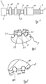
- FIG. 1 is a schematic representation of an embodiment of a built camshaft 1 according to the invention for an internal combustion engine, which is constructed according to the principle of a camshaft with sliding cam elements.
- the built camshaft 1 comprises at least one base shaft 2 with an external toothing 3 and at least one hub 10 connected to the base shaft in a rotationally fixed and immovable manner.
- the base shaft 2 is preferably rod-shaped and can be designed as a hollow shaft or a solid shaft.
- the hub 10 can be, for example, a sensor wheel or a cam, such as a pump cam or a cam for valve actuation.
- the base shaft 2 has an end piece 4, to which, for example, a gear wheel (not shown here) can be attached to drive the camshaft 1.
- the end piece 4 can be formed in one piece with the base shaft 2 or manufactured separately and subsequently mounted. It is also conceivable that no end piece 4 is formed on the base shaft 2, but rather an enlarged diameter or the like. What all variants have in common is that the components can advantageously only be joined from one side of the camshaft 1.
- the assembled camshaft 1 can have several hubs 10 that are fixed in rotation and cannot be moved axially.
- the external toothing 3 of the base shaft 2 is formed, for example, by a multi-tooth profile in the form of an involute toothing.
- the multi-tooth profile of the external toothing 3 can also be designed as a polygon or similar non-circular shape. It is important here that the non-circular shape fixes the hub 10 in a rotationally fixed manner and can transmit or withstand the torque to be transmitted from the base shaft 2 to the hub 10.
- the external toothing 3 can be formed on the rod-shaped base shaft 2, for example, by means of a rolling, milling and/or drawing process.
- the external toothing 3 forms a form-fitting part area 5 and/or a force-fitting part area 6 for the hub 10.
- the form-fitting part area 5 serves, for example, to axially guide the hubs 10 during assembly.
- the hub 10 is fixed axially immovably to the base shaft 2 by means of a press fit, which will be described in more detail later.
- a rotationally fixed connection between the base shaft 2 and the hub 10 can be achieved by the form-fitting part areas 5 of the camshaft 1.
- Mutual support or supplementation of the form-fitting part area 5 and the frictional part area 6 for the purpose of fixing the hub 10 to the base shaft 2 in an end position is provided.
- the frictional part area 6 of the base shaft 2 is formed by the press fit between the base shaft 2 and the hub 10.
- the frictional part area 6 extends at least along the base shaft 2 in such a way that the length of the internal toothing 8 (as in Figure 3 shown) of the hub 10 and its end position on the base shaft 2.
- the frictional connection part area 6 also includes the displacement path of the hub 10.
- both parts namely a form-fit part area 5 and a frictional connection part area 6, are formed axially spaced from one another on the base shaft 2 in such a way that both parts extend axially along the base shaft 2 at least in sections. Both parts advantageously extend completely in the circumferential direction around the base shaft 2, ie the form-fit connection or the frictional connection between the base shaft 2 and the hub 10 are formed distributed over the circumference.
- the external toothing 3 is divided axially into two sub-areas and thus into two form-fitting sub-areas 5 or two force-fitting sub-areas 6.
- An alignment region 7 is formed between the two sub-areas and between the end piece 4 and one of the two sub-areas, in particular the second sub-area of the external toothing 3.
- the alignment region 7 can be formed by subsequently grinding or milling this external toothing 3.
- the external toothing 3 it is also possible for the external toothing 3 to be formed only in sections along the axial length of the base shaft, whereby the alignment regions 7 can also already be formed, in particular by not machining the surface of the base shaft 2 in areas between the machined sections.
- the formation of the alignment regions 7 and the sub-regions, in particular the form-fitting sub-regions 5 or the force-fitting sub-regions 6, of the external toothing 3 can be provided depending on their axial arrangement on the base shaft 2. Subsequent machining of the base shaft 2 or the external toothing 3 to form the alignment region(s) 7 is then preferably not necessary.
- the assembled camshaft 1 has a further, in particular axially displaceable hub 20.
- the hub 20 can be displaced axially along the external toothing, in particular along the formed sub-areas, such as the frictional locking sub-area 6 and/or the positive locking sub-area 5.
- the further hub 20 therefore represents a sliding cam element, as is already sufficiently known from the general state of the art.
- the external toothing 3 of the base shaft 2 forms a positive locking sub-area 5 for the hub 20.
- the hub 20 is guided axially along the base shaft 2 by the positive locking sub-area 5 and is connected to it in a rotationally fixed manner.
- the Figure 2 shows an enlarged section of a cross-section of a base shaft 2 of an embodiment of a camshaft constructed according to the invention.
- a first tooth 3.1 and a second tooth 3.2 are shown with interdental spaces 3.3 and 3.4 formed next to them in the circumferential direction of the base shaft.
- the first interdental space 3.3 is wider here than the second interdental space 3.4.
- the two teeth 3.1, 3.2 have, for example, the same width.
- first or another second tooth can be formed.
- another tooth with a wider tooth width in particular a third tooth with a second tooth width, is formed.
- the number and distribution of the different teeth 3.1, 3.2 or the different interdental spaces 3.3, 3.4 can vary.
- the first 3.1 and the second teeth 3.2 or the first 3.3 and the second tooth spaces 3.4 are evenly and alternately distributed over the circumference of the base shaft 2.
- FIG 3 is an enlarged detail of a cross section of a hub 10 of an embodiment of a camshaft 1 constructed according to the invention.
- the hub 10 has an internal toothing 8 which extends in the axial direction.
- the internal toothing 8 has first teeth 8.1 and second teeth 8.2, each with two different widths, namely a first width 8.1 and a second width 8.2.
- the first teeth 8.1 and the second teeth 8.2 are adjoined by a first intermediate tooth region 8.3 and a second intermediate tooth region 8.4, respectively.
- the first tooth 8.1 is wider in the embodiment shown here than the second tooth 8.2 of the internal toothing 8.
- the number and distribution of the first 8.1 and the second teeth 8.2 or the first 8.3 and the second tooth spaces 8.4 can be varied depending on the design.
- the various teeth 8.1, 8.2 or the various tooth spaces 8.3, 8.4 are evenly distributed alternately over the circumference of the internal toothing 8 of the hub 10.
- the dimensions of the internal toothing 8 of the hub 10 are selected such that the first tooth 8.1 or the first teeth 8.1 form a sliding fit with the first tooth gap 3.3 or the first tooth gaps 3.3 of the external toothing 3 of the base shaft 2.
- the combination of one or more first teeth 8.1 of the internal toothing 8 with one or more second tooth gaps 3.4 of the external toothing 3 results in an overlap and thus a frictional connection or a press connection between the base shaft 2 and the hub 10.
- FIGs 4, 6 and 9 show various stages, in particular process steps of the method according to the invention during the manufacture of a built camshaft 1 according to the invention.
- Figure 4 the base shaft 2 with an end piece 4.
- the external toothing 3 is already formed on the base shaft 2.
- the external toothing 3 is divided into two sub-areas by an alignment area 7, or an alignment area 7 is formed between two sub-areas of the external toothing 3.
- An alignment area 7 is also formed between the end piece 4 and the external toothing.
- the hub 10 In order to enable the hub 10 to be pushed on, the hub 10 must be angularly aligned with respect to the base shaft 2.
- the hub 10 is aligned with the external toothing 3 of the base shaft 2 in such a way that the first tooth 8.1 of the internal toothing 8 of the hub 10, which has a first width B8.1, is aligned with the first tooth gap 3.3 of the external toothing 3 of the base shaft 2, which has a defined width B3.3.
- the second teeth 8.2 (cf. Figure 3 ) of the internal teeth 8 of the hub 10, which have a second width B8.2, are provided with the second tooth gap 3.4, (cf. Figure 2 ) of the external toothing 3 of the base shaft 2, which has a defined width B3.4, is aligned.
- the first width B8.1 of the tooth 8.1 and the first tooth gap 3.3 with its width B3.3 are designed to correlate with each other.
- the width B8.2 of the second tooth 8.2 also correlates with the width B3.4 of the second tooth gap 3.4.
- the hub 10 is threaded onto the base shaft 2 by means of a relative movement between the base shaft 2 and the hub 10.
- Figure 6 shows a further process step in the manufacture of an embodiment of a built-up camshaft 1 according to the invention.
- the hub 10 is axially displaced so far that its internal toothing 8 (see Figure 3 ) is received in the alignment area 7.
- the form-fitting part area 5 does not act on the hub 10 here, whereby the hub 10 can be changed in its angular alignment in this situation, ie can be rotated relative to the base shaft.
- FIG. 7 This condition according to the Figure 6 is in the Figure 7 shown in a longitudinal section.
- the internal toothing 8 of the hub 10 is arranged in the alignment area 7.
- the internal toothing 8 of the hub 10 does not extend over the entire length of the hub 10.
- the alignment area 7 is dimensioned such that it can accommodate the internal toothing 8 of the hub 10 and enable the rotation of the hub 10.
- the Figure 6 shown state in the Figure 8 shown, in particular in a cross section through the base shaft 2 and the hub 10 during the positioning of the hub 10 in the alignment area 7.
- the internal toothing 8 of the hub 10 in particular the teeth 8.1, 8.2 of the internal toothing 8 of the hub 10, have different widths B8.1, B8.2.
- the teeth 8.1, 8.2 of the internal toothing 8 have no positive and/or frictional connection to the base shaft 2.
- the hub 10 can be rotated and angularly aligned relative to the base shaft 2.
- the second teeth 8.2 of the internal toothing 8 of the hub 10 which have a second width B8.2, are engaged with the first tooth spaces 3.3 of the external toothing 3 of the base shaft 2, which have a first width B3.3.
- the first teeth 8.1 of the internal toothing 8 of the hub are wider than the second teeth 8.2, whereby the first tooth spaces 3.3 of the external toothing 3 of the base shaft 2 are wider than the second tooth spaces 3.4.
- the teeth 8.1 and 8.2 of the internal toothing 8 of the hub 10 have an identical width.
- the first teeth 8.1 of the internal toothing 8 of the hub is narrower than the first tooth spaces 3.3, but wider than the second spaces 3.4 of the external toothing 3 of the base shaft 2.
- the Figure 11 shows a design in which several form-locking partial areas 5 and/or force-locking partial areas 6 and an alignment area 7 are formed between them.
- the alignment areas 7 and the form-locking partial areas 5 and/or force-locking partial areas 6 alternate along the base shaft 2, viewed in the axial direction.
- the hub 10 shown in dashed lines is in a position in which it can be angularly aligned.
- This state is also shown in the Figure 12 , which shows an enlarged section of the hub 10 and the base shaft 2 in longitudinal section. This illustrates the corresponding arrangement of the internal toothing 8 in the alignment areas 7.
- the internal toothing 8 of the hub 10 is divided axially in this development, namely into two sections 8.8 and 8.9.
- the internal toothing 8 of the hub 10 is divided axially into more than two sections 8.8, 8.9, in particular three or more sections.
- the alignment areas 7 can also be placed in axial areas of the base shaft 2 in which they have no or a lesser effect for other hubs of the camshaft 1.
- the form-fitting partial areas 5 can represent smaller interruptions for the external toothing 3 of the base shaft 2 in their axial extension, whereby the external toothing 3 can be better used for other hubs and their torque transmission or axial guidance.
- FIG. 13 A further embodiment of a camshaft 1 constructed according to the invention is shown in Figure 13 shown as an enlarged section in cross-section.
- the hub 10 has an internal toothing 8 with first teeth 8.1 and first tooth spaces 8.3.
- the internal toothing 8 of the hub 10 has half the number of teeth to match the base shaft 2 or its external toothing 3.
- the first teeth 8.1 and the first 3.3 and second tooth spaces 3.4 are dimensioned in such a way that when the first teeth 8.1 and the first tooth spaces 3.3 are combined, a sliding fit is formed between them.
- a combination or pairing of the first teeth 8.1 with the second tooth spaces 8.4 results in the formation of a press fit on the respective tooth flanks.
- the advantage of this design is that the angular alignment of the hub 10 can take place in smaller steps or angular increments, which here correspond, for example, to half the number of teeth on the hub 10.
- the ratio of the number of teeth to the tooth spaces can be changed depending on the desired adjustable angular increments.
- the effort required to form a complex and fine internal toothing 8 on the hub 10 can be reduced.
- the tooth division shown should make it clear that the first 3.3 and second tooth spaces 3.4 of the external toothing 3 of the base shaft 2 are not necessarily tied to the formation or the presence of the first 3.1 and second teeth 3.2 of the external toothing 3 of the base shaft 2. Furthermore, variations in the distribution over the circumference of the base shaft 2 or the receiving opening of the hub 10 are also possible.
- the internal toothing 8 of the hub 10 has fewer first teeth 8.1 or second teeth 8.2 than the external toothing 3 of the base shaft has first teeth 3.3 or second tooth spaces 3.4. In this way, several teeth can engage in a tooth space of the external toothing 3 of the base shaft and the hub 10 can be fixed in its angular alignment in smaller steps on the base shaft 2.
- tooth width or the width of the internal and/or external teeth can be varied accordingly.
- a tooth width BZ used to form a press connection between hub 10 and base shaft 2, as in the Figure 14 shown is divided into several teeth 3.1.
- the effective tooth width BZ is divided into two first teeth 3.1, which are formed adjacent to each other on the internal toothing 8 of the hub 10.
- the tooth flanks involved in the interference fit are, as for example in Figure 14 shown, the facing tooth flanks of the teeth 8.1 of the internal toothing 8 and the facing tooth flanks of the teeth 3.1 of the external toothing 3.
- the corresponding areas of the tooth flanks are in Figure 14 highlighted.
- the data for the Figure 14 The effective tooth width of the press connection shown is therefore formed on the circumferential section by means of two teeth 3.1 and a tooth gap 3.3 of the external toothing 3.
- a corresponding tooth gap of the hub 10 for the press connection of hub 10 and base shaft 2 would, for example, have the width BZR.
- the clearance required during assembly is to be created by combining the teeth 8.1 with the tooth gaps 3.3.
- different angle steps are available for the angular alignment, regardless of the tooth width of an individual tooth.
- the design shown is an example of the reversal of the means involved in the press connection between the tooth and the inter-tooth space.
- the tooth used here for the press connection is provided or formed by the external toothing 3 and the inter-tooth space is provided or formed by the hub 10.
- the internal toothing of the hub has fewer teeth than the external toothing of the base shaft.
- several teeth can engage in a tooth space of the external toothing of the base shaft and the hub can be fixed in its angular alignment on the base shaft in smaller steps.
Landscapes
- Engineering & Computer Science (AREA)
- General Engineering & Computer Science (AREA)
- Mechanical Engineering (AREA)
- Valve-Gear Or Valve Arrangements (AREA)
Claims (9)
- Arbre à cames assemblé (1) pour un moteur à combustion interne, l'arbre à cames (1) comprenant un arbre de base (2) et une denture externe (3) s'étendant au moins partiellement de manière axiale le long de l'arbre de base (2), ainsi qu'au moins un moyeu (10) avec une denture interne (8), laquelle est en corrélation avec la denture externe (3) de l'arbre de base (2) de manière à ce que le moyeu (10) soit relié de manière fixe en rotation et non déplaçable axialement avec l'arbre de base (2), la denture externe (3) comprenant au moins une zone de blocage de forme (5) ou une zone de blocage de force (6) s'étendant au moins partiellement de manière axiale le long de l'arbre de base (2), pour disposer le moyeu (10) au moins de manière fixe en forme ou fixe en force, et au moins une zone d'alignement (7) s'étendant au moins partiellement de manière axiale le long de l'arbre de base (2) suit la zone de blocage de forme (5) ou la zone de blocage de force (6) pour aligner angulairement le moyeu (10), caractérisé en ce que la denture externe (3) de la zone de blocage de forme (5) ou de la zone de blocage de force (6) comprend au moins deux espaces entre dents (3.3, 3.4) formés entre les dents (3.1, 3.2) ayant des largeurs différentes, et la denture interne (8) du moyeu (10) comprend au moins une première dent (8.1) corrélant avec le premier espace entre dents (3.3) et ayant une première largeur (B8.1), la première dent (8.1) du moyeu (10) ayant une première largeur (B8.1) formant un ajustement coulissant avec le premier espace entre dents (3.3) ayant une première largeur (B3.3) de l'arbre de base (2), et la connexion de blocage de force du moyeu (10) avec l'arbre de base (2) pour la fixation axiale du moyeu (10) est réalisée en raison d'une liaison par pression formée entre au moins le second espace entre dents (3.4) de la denture externe (3) de l'arbre de base ayant une seconde largeur (B3.4) et la première dent (8.1) de la denture interne (8) du moyeu (10) n'étant pas corrélée ayant une première largeur (B8.1), les au moins deux espaces entre dents (3.3, 3.4) de la denture externe (3) ayant des largeurs différentes étant formés de manière alternée tout autour, la denture interne (8) du moyeu (10) ayant au moins une deuxième dent (8.2) avec une deuxième largeur (B8.2), et la deuxième dent (8.2) formant un ajustement coulissant avec à la fois le premier espace entre dents (3.3) et le deuxième espace entre dents (3.4) de l'arbre de base (2), les premières (8.1) et deuxièmes dents (8.2) étant formées de manière alternée tout autour.
- Arbre à cames (1) selon la revendication 1, caractérisé en ce que la dent (8.1) de la denture interne (8) du moyeu (10) ayant la première largeur (B8.1) est formée plusieurs fois tout autour et est répartie en correspondance avec les premiers et deuxièmes espaces entre dents (3.3, 3.4).
- Arbre à cames (1) selon l'une des revendications 1 à 2, caractérisé en ce que la zone de blocage de forme (5) et/ou la zone de blocage de force (6) est/ sont divisées en au moins deux zones de blocage de forme (6) et/ou de force (7) espacées axialement par la zone d'alignement (7).
- Arbre à cames (1) selon l'une des revendications 1 à 3, caractérisé en ce que plusieurs zones de blocage de forme (5) et/ou zones de blocage de force (6) et plusieurs zones d'alignement (7) s'étendent alternativement en direction axiale le long de l'arbre de base (2).
- Arbre à cames (1) selon l'une des revendications 1 à 4, caractérisé en ce que la denture interne (8) du moyeu (10) est divisée en au moins deux sections avec son extension axiale.
- Procédé de fabrication d'un arbre à cames assemblé (1) selon l'une des revendications précédentes 1 à 5 comprenant les étapes de procédé suivantes :• Fournir un arbre de base (2),• Traitement de surface de l'arbre de base (2) sur au moins une section pour créer la denture externe (3) s'étendant au moins partiellement de manière axiale le long de l'arbre de base (2), laquelle fournit pour au moins un moyeu (10) avec sa denture interne (8) au moins la zone de blocage de forme (5) ou la zone de blocage de force (6) pour garantir la connexion avec l'arbre de base (2), la denture externe (3) ayant au moins deux dents (3.1, 3.2) formant les deux espaces entre dents de largeurs différentes (3.3, 3.4),• Former la zone d'alignement (7) sur l'arbre de base (2), la zone d'alignement (6) s'étendant axialement au moins au niveau de la zone de blocage de forme ou de la zone de blocage de force,• Fournir le moyeu (10) avec une denture interne (8) s'étendant au moins partiellement en direction axiale, laquelle est corrélée avec la denture externe (3) de l'arbre de base (2) et comprend au moins une dent (8.1) ayant une largeur de dent (B8.1), le premier espace entre dents (3.3) étant plus large que le second espace entre dents (3.4),• Monter le moyeu (10), le moyeu (10) étant aligné angulairement de manière à être enfilé sur la denture externe (3) de l'arbre de base (2) de manière à ce que la denture externe (3) corrélant de l'arbre de base (2) et la denture interne (8) du moyeu (10) forment un ajustement coulissant,• Déplacer axialement le moyeu (10) au moins le long de la zone de blocage de forme (5) ou de la zone de blocage de force (6) de l'arbre de base, jusqu'à ce que la denture interne (8) du moyeu (10) soit enfoncée dans la zone d'alignement (7),• Aligner précisément le moyeu (10) en rotation par rapport à la denture externe (3) de l'arbre de base (2) de manière à ce qu'au moins un couple composé de la deuxième denture (3.4) ayant une largeur (B3.4) de la denture externe (3) et de la denture interne (8.1) ayant une première largeur (B8.1) de la denture interne (8) soit axialement aligné,• Déplacer axialement le moyeu (10) au moins le long de la zone de blocage de forme (5) ou de la zone de blocage de force (6) de l'arbre de base (2) jusqu'à sa position finale, une connexion par pression étant formée entre la denture (3) de l'arbre de base (2) ayant une largeur (B3.2) et la denture interne (8) ayant une première largeur (B8.1) du moyeu (10), fixant ainsi le moyeu (10) contre tout déplacement axial.
- Procédé de fabrication d'un arbre à cames assemblé (1) selon la revendication 6, caractérisé en ce qu'au moins la zone de blocage de forme (5) ou la zone de blocage de force (6) est divisée en au moins deux zones de blocage de forme (5) ou de force (6) espacées axialement par la zone d'alignement (7).
- Procédé de fabrication d'un arbre à cames assemblé (1) selon l'une des revendications 6 ou 7, caractérisé en ce que la zone d'alignement (7) est formée par des évidements dans la denture externe (3), par exemple par fraisage ou meulage.
- Procédé de fabrication d'un arbre à cames assemblé (1) selon l'une des revendications 6 à 8, caractérisé en ce que la dent (8.1) de la denture interne (8) du moyeu (10) ayant la première largeur (B8.1) est formée plusieurs fois tout autour et est répartie en correspondance avec les espaces entre dents (3.3).
Applications Claiming Priority (2)
| Application Number | Priority Date | Filing Date | Title |
|---|---|---|---|
| DE102017222607.2A DE102017222607A1 (de) | 2017-12-13 | 2017-12-13 | Gebaute Nockenwelle, sowie Verfahren zur Herstellung einer gebauten Nockenwelle |
| PCT/EP2018/084468 WO2019115581A1 (fr) | 2017-12-13 | 2018-12-12 | Arbre à cames rapportées et son procédé de fabrication |
Publications (2)
| Publication Number | Publication Date |
|---|---|
| EP3724461A1 EP3724461A1 (fr) | 2020-10-21 |
| EP3724461B1 true EP3724461B1 (fr) | 2024-10-16 |
Family
ID=64746554
Family Applications (1)
| Application Number | Title | Priority Date | Filing Date |
|---|---|---|---|
| EP18822318.4A Active EP3724461B1 (fr) | 2017-12-13 | 2018-12-12 | Arbre à cames rapportées et son procédé de fabrication |
Country Status (5)
| Country | Link |
|---|---|
| US (1) | US11098616B2 (fr) |
| EP (1) | EP3724461B1 (fr) |
| CN (1) | CN111479986A (fr) |
| DE (1) | DE102017222607A1 (fr) |
| WO (1) | WO2019115581A1 (fr) |
Citations (1)
| Publication number | Priority date | Publication date | Assignee | Title |
|---|---|---|---|---|
| DE19710847C2 (de) * | 1997-03-15 | 1999-01-07 | Selzer Fertigungstech | Zusammengesetzte Steuerwelle und Verfahren für deren Herstellung |
Family Cites Families (12)
| Publication number | Priority date | Publication date | Assignee | Title |
|---|---|---|---|---|
| RU2078218C1 (ru) * | 1994-12-20 | 1997-04-27 | Алексей Петрович Графчев | Способ изготовления сборного распределительного вала и инструмент для его осуществления |
| JP3433656B2 (ja) * | 1997-10-03 | 2003-08-04 | トヨタ自動車株式会社 | 軸部材の嵌合構造および嵌合方法 |
| JP2002258675A (ja) * | 2000-12-27 | 2002-09-11 | Matsushita Electric Ind Co Ltd | 画像形成装置 |
| JP2003184994A (ja) * | 2001-12-14 | 2003-07-03 | Otics Corp | 複合カムシャフト及びその製造方法 |
| JP2006097485A (ja) * | 2004-09-28 | 2006-04-13 | Musashi Seimitsu Ind Co Ltd | カムシャフト及びその組み立て方法 |
| US7748925B2 (en) * | 2006-09-15 | 2010-07-06 | Aichi Machine Industry Co., Ltd. | Rotating member fixing structure |
| DE102008053723B4 (de) * | 2008-10-29 | 2023-12-07 | Neumayer Tekfor Engineering Gmbh | Gebaute Nockenwelle |
| DE102009024455A1 (de) * | 2009-06-10 | 2011-01-05 | Audi Ag | Gebautes Wellenelement, insbesondere gebaute Nockenwelle für ventilgesteuerte Brennkraftmaschinen |
| DE102009057633B3 (de) * | 2009-12-09 | 2011-03-31 | Thyssenkrupp Presta Teccenter Ag | Verfahren zur Herstellung einer gebauten Nockenwelle, Nockenwellengrundkörper und gebaute Nockenwelle |
| JP5273103B2 (ja) * | 2010-07-15 | 2013-08-28 | 日本精工株式会社 | 雄シャフトと雌シャフトの結合構造 |
| DE102011103544A1 (de) | 2011-06-08 | 2012-12-13 | Schaeffler Technologies AG & Co. KG | Lagerung einer Nockenwelle |
| DE102012109689A1 (de) * | 2012-10-11 | 2014-04-17 | Dr. Ing. H.C. F. Porsche Aktiengesellschaft | Ventiltriebanordnung zur Betätigung von Gaswechselventilen einer Brennkraftmaschine |
-
2017
- 2017-12-13 DE DE102017222607.2A patent/DE102017222607A1/de active Pending
-
2018
- 2018-12-12 WO PCT/EP2018/084468 patent/WO2019115581A1/fr not_active Ceased
- 2018-12-12 CN CN201880080108.2A patent/CN111479986A/zh active Pending
- 2018-12-12 EP EP18822318.4A patent/EP3724461B1/fr active Active
- 2018-12-12 US US16/767,420 patent/US11098616B2/en active Active
Patent Citations (1)
| Publication number | Priority date | Publication date | Assignee | Title |
|---|---|---|---|---|
| DE19710847C2 (de) * | 1997-03-15 | 1999-01-07 | Selzer Fertigungstech | Zusammengesetzte Steuerwelle und Verfahren für deren Herstellung |
Also Published As
| Publication number | Publication date |
|---|---|
| US11098616B2 (en) | 2021-08-24 |
| CN111479986A (zh) | 2020-07-31 |
| US20200386123A1 (en) | 2020-12-10 |
| DE102017222607A1 (de) | 2019-06-13 |
| EP3724461A1 (fr) | 2020-10-21 |
| WO2019115581A1 (fr) | 2019-06-20 |
Similar Documents
| Publication | Publication Date | Title |
|---|---|---|
| DE102010004591B4 (de) | Gebauter Nockenträger für Ventiltrieb | |
| DE102009057633B3 (de) | Verfahren zur Herstellung einer gebauten Nockenwelle, Nockenwellengrundkörper und gebaute Nockenwelle | |
| EP2315920B1 (fr) | Liaison par cannelures et mécanisme de distribution avec liaison par cannelures entre un arbre à cames et des supports de came déplaçables | |
| DE68905065T2 (de) | Nockenwellenzusammenbauverfahren und so hergestellte nockenwelle. | |
| DE3206068C2 (de) | Kupplungsscheibe | |
| EP2340360B1 (fr) | Arbre a cames assemblé et méthode de fabrication | |
| DE102004009074B3 (de) | Gebauter Mehrfachnocken | |
| DE102009013996A1 (de) | Einrichtung zur Verstellung der Exzentrizität für ein Kurbel-CVT-Getriebe | |
| DE102014220858A1 (de) | Verfahren zur Herstellung einer gebauten Nockenwelle | |
| DE69803477T2 (de) | Trommelmotor | |
| WO2015067262A2 (fr) | Douille coulissante pour le montage de roues planétaires | |
| EP1903232A2 (fr) | Arbre à came monté doté de réglages passant sous les composants enfoncés | |
| AT520015B1 (de) | Baugruppe mit einer Steckverzahnung | |
| DE102008046821B4 (de) | Kurbelwelle für eine Brennkraftmaschine mit varibaler Verdichtung und Brennkraftmaschine mit variabler Verdichtung | |
| EP3472481B1 (fr) | Arbre cannelé et procédé de fabrication dudit arbre, procédé de fabrication d'un arbre fonctionnel | |
| EP3723925B1 (fr) | Arbre à cames assemblé et procédé de fabrication d'un arbre à cames assemblé | |
| DE102014217584A1 (de) | Ventiltriebvorrichtung sowie Schaltkulisse | |
| DE19845148C2 (de) | Anlasser | |
| WO2017063813A1 (fr) | Couronne à denture intérieure et à denture frontale, ainsi que procédé de fabrication associé et boîte de vitesses dotée d'une telle couronne | |
| WO2024188684A1 (fr) | Arbre à cames et procédé de fabrication d'un arbre à cames | |
| DE102016204156B3 (de) | Schiebemuffe zum Schalten von Gangstufen eines Schaltgetriebes | |
| WO2019115581A1 (fr) | Arbre à cames rapportées et son procédé de fabrication | |
| EP3608555B1 (fr) | Système d'arbre cannelé pourvu de denture d'engrènement | |
| DE102015204588B4 (de) | Aktor mit einer Reibeinrichtung unter Verwendung eines Schlingfederelementes und Verfahren zur Herstellung des Schlingfederelementes | |
| DE102011052823A1 (de) | Nockenwelle, insbesondere für Kraftfahrzeugmotoren |
Legal Events
| Date | Code | Title | Description |
|---|---|---|---|
| STAA | Information on the status of an ep patent application or granted ep patent |
Free format text: STATUS: UNKNOWN |
|
| STAA | Information on the status of an ep patent application or granted ep patent |
Free format text: STATUS: THE INTERNATIONAL PUBLICATION HAS BEEN MADE |
|
| PUAI | Public reference made under article 153(3) epc to a published international application that has entered the european phase |
Free format text: ORIGINAL CODE: 0009012 |
|
| STAA | Information on the status of an ep patent application or granted ep patent |
Free format text: STATUS: REQUEST FOR EXAMINATION WAS MADE |
|
| 17P | Request for examination filed |
Effective date: 20200713 |
|
| AK | Designated contracting states |
Kind code of ref document: A1 Designated state(s): AL AT BE BG CH CY CZ DE DK EE ES FI FR GB GR HR HU IE IS IT LI LT LU LV MC MK MT NL NO PL PT RO RS SE SI SK SM TR |
|
| AX | Request for extension of the european patent |
Extension state: BA ME |
|
| DAV | Request for validation of the european patent (deleted) | ||
| DAX | Request for extension of the european patent (deleted) | ||
| RAP3 | Party data changed (applicant data changed or rights of an application transferred) |
Owner name: THYSSENKRUPP AG Owner name: THYSSENKRUPP DYNAMIC COMPONENTS TECCENTER AG |
|
| STAA | Information on the status of an ep patent application or granted ep patent |
Free format text: STATUS: EXAMINATION IS IN PROGRESS |
|
| 17Q | First examination report despatched |
Effective date: 20221129 |
|
| GRAP | Despatch of communication of intention to grant a patent |
Free format text: ORIGINAL CODE: EPIDOSNIGR1 |
|
| STAA | Information on the status of an ep patent application or granted ep patent |
Free format text: STATUS: GRANT OF PATENT IS INTENDED |
|
| INTG | Intention to grant announced |
Effective date: 20240521 |
|
| GRAS | Grant fee paid |
Free format text: ORIGINAL CODE: EPIDOSNIGR3 |
|
| GRAA | (expected) grant |
Free format text: ORIGINAL CODE: 0009210 |
|
| STAA | Information on the status of an ep patent application or granted ep patent |
Free format text: STATUS: THE PATENT HAS BEEN GRANTED |
|
| AK | Designated contracting states |
Kind code of ref document: B1 Designated state(s): AL AT BE BG CH CY CZ DE DK EE ES FI FR GB GR HR HU IE IS IT LI LT LU LV MC MK MT NL NO PL PT RO RS SE SI SK SM TR |
|
| REG | Reference to a national code |
Ref country code: GB Ref legal event code: FG4D Free format text: NOT ENGLISH |
|
| REG | Reference to a national code |
Ref country code: CH Ref legal event code: EP |
|
| REG | Reference to a national code |
Ref country code: IE Ref legal event code: FG4D Free format text: LANGUAGE OF EP DOCUMENT: GERMAN |
|
| REG | Reference to a national code |
Ref country code: DE Ref legal event code: R096 Ref document number: 502018015242 Country of ref document: DE |
|
| P01 | Opt-out of the competence of the unified patent court (upc) registered |
Free format text: CASE NUMBER: APP_65618/2024 Effective date: 20241213 |
|
| REG | Reference to a national code |
Ref country code: LT Ref legal event code: MG9D |
|
| REG | Reference to a national code |
Ref country code: NL Ref legal event code: MP Effective date: 20241016 |
|
| PG25 | Lapsed in a contracting state [announced via postgrant information from national office to epo] |
Ref country code: NL Free format text: LAPSE BECAUSE OF FAILURE TO SUBMIT A TRANSLATION OF THE DESCRIPTION OR TO PAY THE FEE WITHIN THE PRESCRIBED TIME-LIMIT Effective date: 20241016 |
|
| PG25 | Lapsed in a contracting state [announced via postgrant information from national office to epo] |
Ref country code: NL Free format text: LAPSE BECAUSE OF FAILURE TO SUBMIT A TRANSLATION OF THE DESCRIPTION OR TO PAY THE FEE WITHIN THE PRESCRIBED TIME-LIMIT Effective date: 20241016 |
|
| PG25 | Lapsed in a contracting state [announced via postgrant information from national office to epo] |
Ref country code: IS Free format text: LAPSE BECAUSE OF FAILURE TO SUBMIT A TRANSLATION OF THE DESCRIPTION OR TO PAY THE FEE WITHIN THE PRESCRIBED TIME-LIMIT Effective date: 20250216 Ref country code: PT Free format text: LAPSE BECAUSE OF FAILURE TO SUBMIT A TRANSLATION OF THE DESCRIPTION OR TO PAY THE FEE WITHIN THE PRESCRIBED TIME-LIMIT Effective date: 20250217 Ref country code: HR Free format text: LAPSE BECAUSE OF FAILURE TO SUBMIT A TRANSLATION OF THE DESCRIPTION OR TO PAY THE FEE WITHIN THE PRESCRIBED TIME-LIMIT Effective date: 20241016 |
|
| PG25 | Lapsed in a contracting state [announced via postgrant information from national office to epo] |
Ref country code: FI Free format text: LAPSE BECAUSE OF FAILURE TO SUBMIT A TRANSLATION OF THE DESCRIPTION OR TO PAY THE FEE WITHIN THE PRESCRIBED TIME-LIMIT Effective date: 20241016 |
|
| PG25 | Lapsed in a contracting state [announced via postgrant information from national office to epo] |
Ref country code: BG Free format text: LAPSE BECAUSE OF FAILURE TO SUBMIT A TRANSLATION OF THE DESCRIPTION OR TO PAY THE FEE WITHIN THE PRESCRIBED TIME-LIMIT Effective date: 20241016 |
|
| PG25 | Lapsed in a contracting state [announced via postgrant information from national office to epo] |
Ref country code: ES Free format text: LAPSE BECAUSE OF FAILURE TO SUBMIT A TRANSLATION OF THE DESCRIPTION OR TO PAY THE FEE WITHIN THE PRESCRIBED TIME-LIMIT Effective date: 20241016 |
|
| PG25 | Lapsed in a contracting state [announced via postgrant information from national office to epo] |
Ref country code: NO Free format text: LAPSE BECAUSE OF FAILURE TO SUBMIT A TRANSLATION OF THE DESCRIPTION OR TO PAY THE FEE WITHIN THE PRESCRIBED TIME-LIMIT Effective date: 20250116 |
|
| PG25 | Lapsed in a contracting state [announced via postgrant information from national office to epo] |
Ref country code: GR Free format text: LAPSE BECAUSE OF FAILURE TO SUBMIT A TRANSLATION OF THE DESCRIPTION OR TO PAY THE FEE WITHIN THE PRESCRIBED TIME-LIMIT Effective date: 20250117 Ref country code: LV Free format text: LAPSE BECAUSE OF FAILURE TO SUBMIT A TRANSLATION OF THE DESCRIPTION OR TO PAY THE FEE WITHIN THE PRESCRIBED TIME-LIMIT Effective date: 20241016 |
|
| PG25 | Lapsed in a contracting state [announced via postgrant information from national office to epo] |
Ref country code: PL Free format text: LAPSE BECAUSE OF FAILURE TO SUBMIT A TRANSLATION OF THE DESCRIPTION OR TO PAY THE FEE WITHIN THE PRESCRIBED TIME-LIMIT Effective date: 20241016 |
|
| PG25 | Lapsed in a contracting state [announced via postgrant information from national office to epo] |
Ref country code: RS Free format text: LAPSE BECAUSE OF FAILURE TO SUBMIT A TRANSLATION OF THE DESCRIPTION OR TO PAY THE FEE WITHIN THE PRESCRIBED TIME-LIMIT Effective date: 20250116 |
|
| PG25 | Lapsed in a contracting state [announced via postgrant information from national office to epo] |
Ref country code: SM Free format text: LAPSE BECAUSE OF FAILURE TO SUBMIT A TRANSLATION OF THE DESCRIPTION OR TO PAY THE FEE WITHIN THE PRESCRIBED TIME-LIMIT Effective date: 20241016 |
|
| PG25 | Lapsed in a contracting state [announced via postgrant information from national office to epo] |
Ref country code: MC Free format text: LAPSE BECAUSE OF FAILURE TO SUBMIT A TRANSLATION OF THE DESCRIPTION OR TO PAY THE FEE WITHIN THE PRESCRIBED TIME-LIMIT Effective date: 20241016 |
|
| PG25 | Lapsed in a contracting state [announced via postgrant information from national office to epo] |
Ref country code: DK Free format text: LAPSE BECAUSE OF FAILURE TO SUBMIT A TRANSLATION OF THE DESCRIPTION OR TO PAY THE FEE WITHIN THE PRESCRIBED TIME-LIMIT Effective date: 20241016 |
|
| REG | Reference to a national code |
Ref country code: DE Ref legal event code: R097 Ref document number: 502018015242 Country of ref document: DE |
|
| PG25 | Lapsed in a contracting state [announced via postgrant information from national office to epo] |
Ref country code: EE Free format text: LAPSE BECAUSE OF FAILURE TO SUBMIT A TRANSLATION OF THE DESCRIPTION OR TO PAY THE FEE WITHIN THE PRESCRIBED TIME-LIMIT Effective date: 20241016 |
|
| PG25 | Lapsed in a contracting state [announced via postgrant information from national office to epo] |
Ref country code: RO Free format text: LAPSE BECAUSE OF FAILURE TO SUBMIT A TRANSLATION OF THE DESCRIPTION OR TO PAY THE FEE WITHIN THE PRESCRIBED TIME-LIMIT Effective date: 20241016 |
|
| PG25 | Lapsed in a contracting state [announced via postgrant information from national office to epo] |
Ref country code: SK Free format text: LAPSE BECAUSE OF FAILURE TO SUBMIT A TRANSLATION OF THE DESCRIPTION OR TO PAY THE FEE WITHIN THE PRESCRIBED TIME-LIMIT Effective date: 20241016 |
|
| PG25 | Lapsed in a contracting state [announced via postgrant information from national office to epo] |
Ref country code: CZ Free format text: LAPSE BECAUSE OF FAILURE TO SUBMIT A TRANSLATION OF THE DESCRIPTION OR TO PAY THE FEE WITHIN THE PRESCRIBED TIME-LIMIT Effective date: 20241016 |
|
| PG25 | Lapsed in a contracting state [announced via postgrant information from national office to epo] |
Ref country code: IT Free format text: LAPSE BECAUSE OF FAILURE TO SUBMIT A TRANSLATION OF THE DESCRIPTION OR TO PAY THE FEE WITHIN THE PRESCRIBED TIME-LIMIT Effective date: 20241016 |
|
| REG | Reference to a national code |
Ref country code: CH Ref legal event code: PL |
|
| PG25 | Lapsed in a contracting state [announced via postgrant information from national office to epo] |
Ref country code: LU Free format text: LAPSE BECAUSE OF NON-PAYMENT OF DUE FEES Effective date: 20241212 |
|
| PLBE | No opposition filed within time limit |
Free format text: ORIGINAL CODE: 0009261 |
|
| STAA | Information on the status of an ep patent application or granted ep patent |
Free format text: STATUS: NO OPPOSITION FILED WITHIN TIME LIMIT |
|
| PG25 | Lapsed in a contracting state [announced via postgrant information from national office to epo] |
Ref country code: SE Free format text: LAPSE BECAUSE OF FAILURE TO SUBMIT A TRANSLATION OF THE DESCRIPTION OR TO PAY THE FEE WITHIN THE PRESCRIBED TIME-LIMIT Effective date: 20241016 |
|
| 26N | No opposition filed |
Effective date: 20250717 |
|
| REG | Reference to a national code |
Ref country code: BE Ref legal event code: MM Effective date: 20241231 |
|
| PG25 | Lapsed in a contracting state [announced via postgrant information from national office to epo] |
Ref country code: BE Free format text: LAPSE BECAUSE OF NON-PAYMENT OF DUE FEES Effective date: 20241231 |
|
| PG25 | Lapsed in a contracting state [announced via postgrant information from national office to epo] |
Ref country code: CH Free format text: LAPSE BECAUSE OF NON-PAYMENT OF DUE FEES Effective date: 20241231 |
|
| PG25 | Lapsed in a contracting state [announced via postgrant information from national office to epo] |
Ref country code: IE Free format text: LAPSE BECAUSE OF NON-PAYMENT OF DUE FEES Effective date: 20241212 |
|
| PGFP | Annual fee paid to national office [announced via postgrant information from national office to epo] |
Ref country code: DE Payment date: 20251211 Year of fee payment: 8 |
|
| PGFP | Annual fee paid to national office [announced via postgrant information from national office to epo] |
Ref country code: GB Payment date: 20251219 Year of fee payment: 8 |
|
| PGFP | Annual fee paid to national office [announced via postgrant information from national office to epo] |
Ref country code: FR Payment date: 20251229 Year of fee payment: 8 |
|
| REG | Reference to a national code |
Ref country code: AT Ref legal event code: MM01 Ref document number: 1733066 Country of ref document: AT Kind code of ref document: T Effective date: 20241212 |
|
| PG25 | Lapsed in a contracting state [announced via postgrant information from national office to epo] |
Ref country code: AT Free format text: LAPSE BECAUSE OF NON-PAYMENT OF DUE FEES Effective date: 20241212 |