EP3724972B1 - Serre-joint à ressort destiné à être fixé à un conducteur électrique d'une machine électrique - Google Patents
Serre-joint à ressort destiné à être fixé à un conducteur électrique d'une machine électrique Download PDFInfo
- Publication number
- EP3724972B1 EP3724972B1 EP18811227.0A EP18811227A EP3724972B1 EP 3724972 B1 EP3724972 B1 EP 3724972B1 EP 18811227 A EP18811227 A EP 18811227A EP 3724972 B1 EP3724972 B1 EP 3724972B1
- Authority
- EP
- European Patent Office
- Prior art keywords
- spring
- electrical conductor
- sensor holder
- leg
- spring leg
- Prior art date
- Legal status (The legal status is an assumption and is not a legal conclusion. Google has not performed a legal analysis and makes no representation as to the accuracy of the status listed.)
- Active
Links
Images

Classifications
-
- H—ELECTRICITY
- H02—GENERATION; CONVERSION OR DISTRIBUTION OF ELECTRIC POWER
- H02K—DYNAMO-ELECTRIC MACHINES
- H02K11/00—Structural association of dynamo-electric machines with electric components or with devices for shielding, monitoring or protection
- H02K11/20—Structural association of dynamo-electric machines with electric components or with devices for shielding, monitoring or protection for measuring, monitoring, testing, protecting or switching
- H02K11/25—Devices for sensing temperature, or actuated thereby
-
- G—PHYSICS
- G01—MEASURING; TESTING
- G01K—MEASURING TEMPERATURE; MEASURING QUANTITY OF HEAT; THERMALLY-SENSITIVE ELEMENTS NOT OTHERWISE PROVIDED FOR
- G01K1/00—Details of thermometers not specially adapted for particular types of thermometer
- G01K1/14—Supports; Fastening devices; Arrangements for mounting thermometers in particular locations
- G01K1/143—Supports; Fastening devices; Arrangements for mounting thermometers in particular locations for measuring surface temperatures
-
- H—ELECTRICITY
- H01—ELECTRIC ELEMENTS
- H01R—ELECTRICALLY-CONDUCTIVE CONNECTIONS; STRUCTURAL ASSOCIATIONS OF A PLURALITY OF MUTUALLY-INSULATED ELECTRICAL CONNECTING ELEMENTS; COUPLING DEVICES; CURRENT COLLECTORS
- H01R4/00—Electrically-conductive connections between two or more conductive members in direct contact, i.e. touching one another; Means for effecting or maintaining such contact; Electrically-conductive connections having two or more spaced connecting locations for conductors and using contact members penetrating insulation
- H01R4/28—Clamped connections, spring connections
- H01R4/48—Clamped connections, spring connections utilising a spring, clip, or other resilient member
- H01R4/4809—Clamped connections, spring connections utilising a spring, clip, or other resilient member using a leaf spring to bias the conductor toward the busbar
- H01R4/48185—Clamped connections, spring connections utilising a spring, clip, or other resilient member using a leaf spring to bias the conductor toward the busbar adapted for axial insertion of a wire end
- H01R4/4819—Clamped connections, spring connections utilising a spring, clip, or other resilient member using a leaf spring to bias the conductor toward the busbar adapted for axial insertion of a wire end the spring shape allowing insertion of the conductor end when the spring is unbiased
- H01R4/4823—Multiblade spring
-
- H—ELECTRICITY
- H02—GENERATION; CONVERSION OR DISTRIBUTION OF ELECTRIC POWER
- H02K—DYNAMO-ELECTRIC MACHINES
- H02K3/00—Details of windings
- H02K3/46—Fastening of windings on the stator or rotor structure
- H02K3/50—Fastening of winding heads, equalising connectors, or connections thereto
-
- H—ELECTRICITY
- H01—ELECTRIC ELEMENTS
- H01R—ELECTRICALLY-CONDUCTIVE CONNECTIONS; STRUCTURAL ASSOCIATIONS OF A PLURALITY OF MUTUALLY-INSULATED ELECTRICAL CONNECTING ELEMENTS; COUPLING DEVICES; CURRENT COLLECTORS
- H01R4/00—Electrically-conductive connections between two or more conductive members in direct contact, i.e. touching one another; Means for effecting or maintaining such contact; Electrically-conductive connections having two or more spaced connecting locations for conductors and using contact members penetrating insulation
- H01R4/28—Clamped connections, spring connections
- H01R4/48—Clamped connections, spring connections utilising a spring, clip, or other resilient member
- H01R4/4809—Clamped connections, spring connections utilising a spring, clip, or other resilient member using a leaf spring to bias the conductor toward the busbar
- H01R4/4846—Busbar details
- H01R4/4848—Busbar integrally formed with the spring
Definitions
- the invention relates to a spring clip for attaching to an electrical conductor of an electrical machine, the spring clip having a sensor holder for receiving a temperature sensor and a spring arm, the temperature sensor being fixable in the sensor holder via the spring arm, and the sensor holder being able to be pressed onto the electrical conductor .
- the invention relates to the use of the spring clip according to the invention for arrangement on an electrical conductor of an electrical machine.
- the invention further relates to an electrical machine with a stator, the stator having at least one electrical conductor and the spring clip according to the invention being arranged on the electrical conductor.
- the WO 2005 034 152 A2 describes a method for connecting a detachable winding to a stationary winding connector, the winding connector having a spring terminal or a clip according to the preamble of claim 1.
- the EP 0 727 864 A2 discloses an interconnection arrangement for an electric motor.
- a spring clip for plugging onto an electrical conductor of an electrical machine, having a first spring leg and a second spring leg adjoining the first spring leg, the first spring leg and the second spring leg being arranged and / or designed in such a way that between a free the first end portion of the first spring leg and a free second end portion of the second spring leg a receiving opening for receiving an electrical conductor is formed, and this can be clamped between the first end portion and the second end portion, the second spring leg has a sensor holder and a spring arm with a pressure tab, and A spring force can be exerted via the spring arm, so that a sensor which is arranged and / or can be arranged in the sensor holder is in the The sensor holder can be fixed, and the sensor holder can be pressed onto the electrical conductor.
- a spring clip which has a first spring leg and a second spring leg adjoining the first spring leg.
- a spring clip is specified with a first and a second spring leg.
- the first spring leg and the second spring leg are arranged with respect to one another in such a way that a receiving opening is formed between a free first end section of the first spring leg and a free second end section of the second spring leg.
- a conductor end of an electrical conductor which is usually a neutral conductor, can be guided through the receiving opening, the electrical conductor being clamped between the respective first end section and the second end section.
- the spring clip can be arranged in a positionally secure and / or self-adjusting manner on the electrical conductor.
- the second spring leg has a sensor holder and a spring arm with a pressure tab.
- the sensor holder is preferably set up and designed to accommodate a sensor, in particular a temperature sensor.
- a spring force can be exerted via the spring arm, so that the sensor arranged in the sensor holder can be fixed in position in the sensor holder via the pressure tab.
- the sensor holder in turn, can be pressed onto the electrical conductor.
- the sensor holder can be designed to be resilient, whereby it is also conceivable that the sensor is pressed against the sensor holder via the spring force of the spring arm and, moreover, the sensor holder can be pressed against the electrical conductor.
- a spring clamp which can be easily plugged onto the electrical conductor and clamped to it in a self-adjusting manner.
- a temperature sensor can be positioned securely in position via the spring arm in a self-adjusting manner in the sensor holder and can be pressed against the electrical conductor, so that the temperature sensor can be connected to and / or placed against the electrical conductor in a position-securely manner.
- the temperature sensor it is not absolutely necessary here for the temperature sensor to be able to be connected and / or applied directly or at least in sections directly to the electrical conductor.
- the sensor holder can be formed at least in sections between the temperature sensor and the electrical conductor.
- the term "self-adjusting" means that the clamping force of the spring clamp and / or the spring force of the spring arm is designed in such a way that a temperature fluctuation-related change in cross-section of the electrical conductor inserted into the spring clamp is compensated for by the clamping force of the spring clamp and that the Spring clamp on the electrical conductor can be guaranteed or a compensation of the spring force of the spring arm takes place, so that the sensor can be fixed in position in the sensor holder and can be securely pressed against the electrical conductor.
- a preferred development of the invention is that the sensor holder is arranged and / or formed between the second end section of the second spring leg and the transition area between the first spring leg and the second spring leg. Accordingly, the sensor holder is formed directly in the second spring leg.
- the sensor holder is U-shaped, the upright arms of the U-shaped sensor holder facing away from the second end section of the second spring leg.
- the temperature sensor can preferably be arranged at least in sections on the upright arms of the U-shaped sensor holder.
- a preferred development of the invention lies in the fact that the end regions of the upright arms of the U-shaped sensor holder are folded up and / or folded over.
- the term “edging up” and / or “bending over” is to be understood as bending the end regions of the upright arms.
- the end regions are preferably bent in a direction perpendicular to the direction in which the electrical conductor is inserted into the spring terminal.
- the bent end regions thus represent a stop for the temperature sensor, so that it has a stop in at least one direction.
- the spring arm is connected and / or formed in the transition area between the first spring leg and the second spring leg. This means that the spring arm is attached to this transition area with a spring arm end that is spaced apart from the spring tab.
- the spring force of the spring arm can be aligned in such a way that the temperature sensor that can be arranged in the sensor holder can be fixed in the sensor holder in a positionally secure manner.
- a preferred development of the invention is that the spring force of the spring arm acts in a direction perpendicular to the direction of insertion of the electrical conductor through the receiving opening.
- the U-shaped sensor holder is aligned at least in sections parallel to the insertion direction of the electrical conductor through the receiving opening. This means that a temperature sensor arranged in the sensor holder is pressed onto the sensor holder via the spring arm and the sensor holder is placed on the electrical conductor. In this way, a self-adjusting fixation of the temperature sensor on the electrical conductor can be provided via the spring arm.
- the second end section of the second spring leg is connected to the first spring leg via two longitudinal struts arranged at a distance from one another. Consequently, the second points Spring legs open the two longitudinal struts, a first longitudinal strut end being connected to the first spring leg in the transition area between the second spring leg and the first spring leg, and a second longitudinal strut end being connected to the second end section.
- the longitudinal struts are bent in such a way that they are designed to be resilient. In this way, a clamping effect of the free end sections can be brought about with respect to one another, so that the electrical conductor can be clamped between the first end section and the second end section.
- a preferred development of the invention provides that the spring arm and / or the sensor holder is formed between the two longitudinal struts.
- the spring clip is designed in one piece. In this way, a very robust spring clip can be produced, which can also be produced inexpensively.
- such a spring clip can be made from a plastic or from a metallic material. It can be provided here that the spring clip is manufactured by means of an additive manufacturing process. A spring clip made of a plastic can preferably be produced by injection molding. A particularly preferred development of the invention is that the spring clip is designed as a stamped and bent part. In this way, the spring clip can be manufactured in a particularly inexpensive manner and in large numbers in a simple manner. If the spring clip is designed as a stamped and bent part, it is particularly preferably formed from a metallic material and / or has a metallic material.
- a metallic material has the advantage that it can conduct the temperature very well, so that it is not absolutely necessary for reliable temperature detection of the electrical conductor inserted into the spring clamp the temperature sensor is directly adjacent to the electrical conductor. Accordingly, the sensor holder can also be formed between the temperature sensor and the electrical conductor.
- the invention also relates to the use of the spring clip according to the invention on an electrical conductor of an electrical machine, wherein the spring clip can be plugged onto a conductor end of the electrical conductor via the receiving opening and can be clamped to it, so that the conductor end is at least partially between the first spring leg and the second spring leg is arranged, in the sensor holder, a temperature sensor can be arranged, and the sensor holder can be pressed onto the electrical conductor.
- one aspect of the use of the spring clip according to the invention is that the spring clip can be plugged onto a conductor end of the electrical conductor, the conductor end being guided through the receiving opening of the spring clip and the conductor end being clamped or clamped between the first end section and the second end section. is jammed.
- a temperature sensor can be arranged in the sensor holder of the second spring leg in order to detect the temperature of the electrical conductor or the end of the conductor. The temperature sensor can be pressed onto the sensor holder via the spring arm. The sensor holder, in turn, can be pressed against the electrical conductor so that the temperature sensor can detect the temperature of the electrical conductor.
- the temperature sensor is pressed against the end of the conductor via the spring arm, so that the temperature sensor is also in self-adjusting contact with the end of the conductor, whereby it can be connected to the end of the conductor in such a way that the temperature of the end of the conductor can be detected.
- the invention relates to an electrical machine with a stator, the stator at least one electrical machine Has conductor, the spring clip according to the invention is attached to a conductor end of the electrical conductor and clamped to the conductor end, a temperature sensor is arranged in the sensor holder and fixed in the sensor holder via the spring arm, and the sensor holder is pressed against the electrical conductor.
- An electrical machine is preferably to be understood as a starter generator, in particular a 48 volt belt starter generator.
- a spring clip 10 is shown for plugging onto an electrical conductor 12 of an electrical machine.
- the spring clip 10 has a first spring leg 14 and a second spring leg 16 adjoining the first spring leg 14.
- the first spring leg 14 and the second spring leg 16 thus adjoin one another.
- the first spring leg 14 and the second spring leg 16 are arranged and designed in relation to one another in such a way that between a free first end section 18 of the first spring leg 14 and a free second end section 20 of the second spring leg 16, a receiving opening 22 for receiving the electrical conductor 12 is formed.
- the electrical conductor 12 ( Fig. 2 ) can be clamped between the first end section 18 and the second end section 20 so that the spring clip is fastened or fixed in a positionally secure and self-adjusting manner on the conductor end 46 of the electrical conductor 12.
- the second spring leg 16 comprises a sensor holder 24 and a spring arm 26 with a pressure tab 28, whereby a spring force can be exerted via the spring arm 26, so that a sensor 30 arranged in the sensor holder 24, in particular a temperature sensor, is via the pressure tab 28 in the sensor holder 24 is fixable.
- the sensor holder 24 can be pressed against the electrical conductor 12, so that the sensor holder 24 rests against the electrical conductor 12 at least in sections. In this way, contact of the temperature sensor 30 with the electrical conductor 12 can be established in order to detect the temperature of the electrical conductor 12.
- the temperature sensor 30 is fixed in the sensor holder 24 in a self-adjusting manner via the spring arm 26 and the sensor holder 24 is pressed against the electrical conductor 12, a self-adjusting fastening of the temperature sensor 30 on the electrical conductor 12 via the spring clip 10 can be provided.
- the second end section 20 of the second spring leg 16 is connected to the first spring leg 14 via two longitudinal struts 32 arranged at a distance from one another.
- a first longitudinal strut end 34 is connected to the first spring leg 14 in the transition region 36 between the first spring leg 14 and the second spring leg 16.
- a second longitudinal strut end 38 is connected to the second end section 20.
- the second spring leg 16 is designed to be resilient via the longitudinal struts 32, so that the electrical conductor 12 that can be plugged in or inserted through the receiving opening 22 between the first end portion 18 and the second end portion 20 can be clamped.
- the sensor holder 24 is arranged between the second end section 20 and the transition region 36.
- the sensor holder 24 has a U-shaped configuration, the upright arms 40 of the U-shaped sensor holder 24 facing away from the second end section 20 of the second spring leg 16. In other words, this means that the upright arms 40 of the U-shaped sensor holder 24 extend in the longitudinal direction of the electrical conductor 12.
- the upright arms 40 extend at least in sections parallel to the longitudinal direction of the electrical conductor 12 or parallel to the insertion direction of the electrical conductor 12 through the receiving opening 22.
- the upright arms 40 also serve as a support and / or support for the temperature sensor 30.
- the end regions 42 of the upright arms 40 of the U-shaped sensor holder 24 are canted or folded. This means that the end regions 42 are bent over. The end regions 42 are bent over in a direction essentially perpendicular to the direction in which the electrical conductor 12 is inserted into the spring terminal 10. In this way, the end regions 42 can position the temperature sensor 30 arranged in the sensor holder 24 in a positionally secure manner in at least one direction.
- the spring arm 26 is connected in the transition area 36 between the first spring leg 14 and the second spring leg 16. This means that the spring arm 26 is connected to the first spring leg 14 with a spring arm end 44 in the transition region 36.
- the spring force of the spring arm 26 acts in a direction perpendicular to the insertion direction of the electrical conductor 12 through the receiving opening 22. This also means that the spring force of the spring arm 26 acts in a direction perpendicular to the longitudinal direction of the electrical conductor 12.
- the spring arm 26 and the sensor holder 24 are formed between the two longitudinal struts 32.
- the spring clip 10 is designed in one piece and also as a stamped and bent part, the spring clip 10 also having a metallic material. In this way, the spring clip 10 can be produced in large numbers particularly inexpensively.
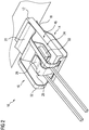
- Figure 2 is that out Figure 1 known spring clip 10 is shown, the spring clip 10 being pushed onto the electrical conductor 12.
- a conductor end 46 engages through the receiving opening 22 so that the conductor end 46 is arranged between the first spring leg 14 and the second spring leg 16.
- the temperature sensor 30 is arranged in the sensor holder 24 and is fixed in a secure position in the sensor holder 24 via the spring arm 26.
- the sensor holder 24 is pressed onto the electrical conductor 12 or onto the conductor end 46 of the electrical conductor 12.
- the spring force of the spring arm 26 acts in a direction perpendicular to the longitudinal direction of the electrical conductor 12 or in a direction perpendicular to the direction in which the electrical conductor 12 is inserted into the spring terminal 10.
- a spring terminal 10 that is particularly inexpensive to manufacture which, in a simple manner can be plugged onto the electrical conductor 12, and can connect the temperature sensor 30 to the electrical conductor 12 in a simple manner, so that reliable temperature detection of the electrical conductor 12 can be made possible.
Landscapes
- Engineering & Computer Science (AREA)
- Power Engineering (AREA)
- Microelectronics & Electronic Packaging (AREA)
- Physics & Mathematics (AREA)
- General Physics & Mathematics (AREA)
- Measuring Temperature Or Quantity Of Heat (AREA)
Claims (12)
- Borne à ressorts (10) destinée à être emmanchée sur un conducteur électrique (12) d'une machine électrique, présentantune première branche de ressort (14) et une deuxième branche de ressort (16) adjacente à la première branche de ressort (14), la première branche de ressort (14) et la deuxième branche de ressort (16) étant disposées l'une par rapport à l'autre et/ou réalisées de telle sorte qu'entre une première partie d'extrémité libre (18) de la première branche de ressort (14) et une deuxième partie d'extrémité libre (20) de la deuxième branche de ressort (16) est réalisée une ouverture de réception (22) pour recevoir le conducteur électrique (12) et celui-ci peut être serré entre la première partie d'extrémité (18) et la deuxième partie d'extrémité (20),caractérisée en ce que la deuxième branche de ressort (16) présente un support de capteur (24) et un bras de ressort (26) doté d'une languette de pression (28), et en ce qu'une force de ressort peut être exercée par l'intermédiaire du bras de ressort (26) de sorte qu'un capteur (30) disposé et/ou pouvant être disposé dans le support de capteur (24) peut être fixé dans le support de capteur (24) par l'intermédiaire de la languette de pression (28), et le support de capteur (24) peut être pressé contre le conducteur électrique (12) .
- Borne à ressorts selon la revendication 1, caractérisée en ce que le support de capteur (24) est disposé et/ou réalisé entre la deuxième partie d'extrémité (20) de la deuxième branche de ressort (16) et la zone de transition (36) entre la première branche de ressort (14) et la deuxième branche de ressort (16).
- Borne à ressorts selon la revendication 1 ou 2, caractérisée en ce que le support de capteur (24) est réalisé en forme de U, les bras redressés (40) du support de capteur (24) en forme de U étant détournés de la deuxième partie d'extrémité (20) de la deuxième branche de ressort (16).
- Borne à ressorts selon la revendication 3, caractérisée en ce que les zones d'extrémité (42) des bras redressés (40) du support de capteur (24) en forme de U sont repliées vers le haut et/ou vers le bas.
- Borne à ressorts selon l'une quelconque des revendications précédentes, caractérisée en ce que le bras de ressort (26) est rattaché dans la zone de transition (36) entre la première branche de ressort (14) et la deuxième branche de ressort (16).
- Borne à ressorts selon l'une quelconque des revendications précédentes, caractérisée en ce que la force de ressort du bras de ressort (26) agit dans une direction perpendiculaire à la direction d'enfichage du conducteur électrique (12) à travers l'ouverture de réception (22).
- Borne à ressorts selon l'une quelconque des revendications précédentes, caractérisée en ce que la deuxième partie d'extrémité (20) de la deuxième branche de ressort (16) est rattachée à la première branche de ressort (14) par l'intermédiaire de deux barrettes longitudinales (32) disposées à distance l'une de l'autre.
- Borne à ressorts selon la revendication 7, caractérisée en ce que le bras de ressort (26) et/ou le support de capteur (24) sont réalisés entre les deux barrettes longitudinales (32).
- Borne à ressorts selon l'une quelconque des revendications précédentes, caractérisée en ce que la borne à ressorts (10) est réalisée d'un seul tenant.
- Borne à ressorts selon l'une quelconque des revendications précédentes, caractérisée en ce que la borne à ressorts (10) est réalisée sous forme de pièce découpée pliée.
- Utilisation d'une borne à ressorts (10) selon l'une quelconque des revendications précédentes destinée à être disposée sur un conducteur électrique (12) d'une machine électrique, dans laquellela borne à ressorts (10) peut être emmanchée à travers l'ouverture de réception (22) sur une extrémité de conducteur (46) du conducteur électrique (12) et peut être serrée avec celui-ci de sorte que l'extrémité de conducteur (46) est disposée au moins par endroits entre la première branche de ressort (14) et la deuxième branche de ressort (16), etun capteur de température (30) peut être disposé dans le support de capteur (24), etle support de capteur (24) peut être pressé contre le conducteur électrique (12).
- Machine électrique comprenant un stator, dans laquellele stator présente au moins un conducteur électrique (12),sur une extrémité de conducteur du conducteur électrique (12) une borne à ressorts (10) selon l'une quelconque des revendications 1 à 10 est emmanchée sur et serrée avec l'extrémité de conducteur (46),un capteur de température (30) est disposé dans le support de capteur (24) et est fixé par l'intermédiaire du bras de ressort (26) dans le support de capteur (24), etle support de capteur (24) est pressé contre le conducteur électrique (12).
Applications Claiming Priority (2)
| Application Number | Priority Date | Filing Date | Title |
|---|---|---|---|
| DE102017222543.2A DE102017222543A1 (de) | 2017-12-13 | 2017-12-13 | Federklemme zum Aufstecken auf einen elektrischen Leiter einer elektrischen Maschine |
| PCT/EP2018/082735 WO2019115224A1 (fr) | 2017-12-13 | 2018-11-27 | Serre-joint à ressort destiné à être fixé à un conducteur électrique d'une machine électrique |
Publications (2)
| Publication Number | Publication Date |
|---|---|
| EP3724972A1 EP3724972A1 (fr) | 2020-10-21 |
| EP3724972B1 true EP3724972B1 (fr) | 2022-01-05 |
Family
ID=64556900
Family Applications (1)
| Application Number | Title | Priority Date | Filing Date |
|---|---|---|---|
| EP18811227.0A Active EP3724972B1 (fr) | 2017-12-13 | 2018-11-27 | Serre-joint à ressort destiné à être fixé à un conducteur électrique d'une machine électrique |
Country Status (5)
| Country | Link |
|---|---|
| US (1) | US11502582B2 (fr) |
| EP (1) | EP3724972B1 (fr) |
| CN (1) | CN111566912B (fr) |
| DE (1) | DE102017222543A1 (fr) |
| WO (1) | WO2019115224A1 (fr) |
Families Citing this family (15)
| Publication number | Priority date | Publication date | Assignee | Title |
|---|---|---|---|---|
| EP3537579B1 (fr) * | 2018-03-07 | 2022-05-11 | Vitesco Technologies GmbH | Anneau d'isolation permettant d'isoler des enroulements d'extrémité d'un stator générateur destiné à un véhicule électrique hybride |
| DE102019121203A1 (de) * | 2019-04-26 | 2020-10-29 | Schaeffler Technologies AG & Co. KG | Elektrische Maschine |
| DE202020101413U1 (de) * | 2019-12-19 | 2020-04-06 | Tdk Electronics Ag | Sensorvorrichtung, elektrische Einrichtung mit Sensorvorrichtung und Fahrzeug mit Sensorvorrichtung |
| US20210372498A1 (en) * | 2020-05-27 | 2021-12-02 | Massachusetts Institute Of Technology | Two-Dimensional Folded Beam-Based Passive Energy Absorber |
| DE102020211528A1 (de) * | 2020-09-15 | 2022-03-17 | Robert Bosch Gesellschaft mit beschränkter Haftung | Vorrichtung und Verfahren zum Anbringen eines Temperatursensors an einer elektrischen Maschine, Sensorvorrichtung und elektrische Maschine |
| DE102020215884A1 (de) | 2020-12-15 | 2022-06-15 | Volkswagen Aktiengesellschaft | Sensoranordnung für einen Elektromotor, Elektromotor mit einer solchen sowie Verfahren zur Einbindung eines Messelementes in einen Elektromotor |
| DE202021102249U1 (de) | 2021-04-27 | 2021-07-08 | Tdk Electronics Ag | Prüfanordnung und Temperatursensor |
| DE102021110764A1 (de) | 2021-04-27 | 2022-10-27 | Tdk Electronics Ag | Prüfanordnung und Temperatursensor |
| DE102021116111A1 (de) * | 2021-06-22 | 2022-12-22 | Tdk Electronics Ag | Messaufbau und Halterung |
| JP7593344B2 (ja) * | 2022-01-24 | 2024-12-03 | 株式会社デンソー | センサ固定具及び温度検出装置 |
| EP4254745A1 (fr) | 2022-03-31 | 2023-10-04 | Valeo eAutomotive Germany GmbH | Stator pour une machine électrique |
| EP4266557A1 (fr) | 2022-04-21 | 2023-10-25 | Valeo eAutomotive Germany GmbH | Dispositif stator pour une machine électrique |
| DE102022112038A1 (de) | 2022-05-13 | 2023-11-16 | Ebm-Papst Mulfingen Gmbh & Co. Kg | Sensorhalter zum Anpressen eines Temperatursensors an eine Wicklung eines Elektromotors |
| DE102022207562A1 (de) | 2022-07-25 | 2024-01-25 | Volkswagen Aktiengesellschaft | Sensoranordnung |
| CN222166328U (zh) * | 2024-02-07 | 2024-12-13 | 宁德时代新能源科技股份有限公司 | 温度传感器的壳体、温度传感器、电池及用电装置 |
Citations (2)
| Publication number | Priority date | Publication date | Assignee | Title |
|---|---|---|---|---|
| DE3817080C2 (fr) * | 1987-06-06 | 1993-06-24 | Hanning Elektro-Werke Gmbh & Co, 4811 Oerlinghausen, De | |
| US7175469B1 (en) * | 2006-07-21 | 2007-02-13 | Tyco Electronics Corporation | Connector having dual tabbed wire trap |
Family Cites Families (17)
| Publication number | Priority date | Publication date | Assignee | Title |
|---|---|---|---|---|
| DE19505557A1 (de) * | 1995-02-18 | 1996-08-22 | Mulfingen Elektrobau Ebm | Verschaltungsanordnung für einen Elektromotor |
| DE112004001807T5 (de) * | 2003-09-29 | 2006-07-13 | Siemens Energy & Automation, Inc. | System und Verfahren zum Verbinden einer demontierbaren Spule mit feststehenden Spulenanschlusskontakten |
| DE102004027510A1 (de) * | 2004-06-04 | 2005-12-22 | Robert Bosch Gmbh | Kontakthalter zur Herstellung einer Klemmkontaktierung |
| CA2559291C (fr) | 2005-09-08 | 2015-01-27 | Progressive Dynamics, Inc. | Convertisseur d'alimentation |
| JP5609275B2 (ja) | 2010-06-02 | 2014-10-22 | 日産自動車株式会社 | 温度センサの取り付け構造および温度センサの取り付け方法 |
| US8800542B1 (en) | 2010-07-20 | 2014-08-12 | John Matthew Kennington | Automatic temperature control device for solid fuel fired food cooker |
| JP5720185B2 (ja) | 2010-11-04 | 2015-05-20 | アイシン精機株式会社 | 電動モータおよびその電動モータを用いた車両用駆動装置 |
| KR20140129388A (ko) | 2010-11-19 | 2014-11-06 | 제이엑스 닛코 닛세키 킨조쿠 가부시키가이샤 | 고순도 란탄의 제조 방법, 고순도 란탄, 고순도 란탄으로 이루어지는 스퍼터링 타깃 및 고순도 란탄을 주성분으로 하는 메탈 게이트막 |
| CN102536769A (zh) * | 2010-12-13 | 2012-07-04 | 上海珂纳电气机械有限公司 | 内置式热保护器固定装置及固定结构 |
| CN104113165B (zh) * | 2013-07-17 | 2016-08-10 | 广东威灵电机制造有限公司 | 电机温控器的固定结构及其应用的电机 |
| JP5726277B1 (ja) * | 2013-11-29 | 2015-05-27 | 三菱電機株式会社 | 回転電機、回転電機の固定子、及び回転電機の固定子の製造方法 |
| DE102014223353A1 (de) | 2014-11-17 | 2016-05-19 | Robert Bosch Gmbh | Vorrichtung zum Befestigen und Kontaktieren eines elektrischen Bauelements und Verfahren zum Herstellen der Vorrichtung |
| JP6481353B2 (ja) * | 2014-12-08 | 2019-03-13 | 日産自動車株式会社 | 回転電機のステータ |
| CN107615026B (zh) | 2015-05-25 | 2019-11-26 | 加特可株式会社 | 温度传感器支架 |
| US10115503B2 (en) | 2016-01-07 | 2018-10-30 | Yazaki North America, Inc. | Terminal-thermistor assembly |
| DE102016119430A1 (de) | 2016-10-12 | 2018-04-12 | Epcos Ag | Anlegetemperaturmessfühler |
| DE102017210433A1 (de) | 2017-06-21 | 2018-12-27 | Em-Motive Gmbh | Statoranordnung für eine elektrische Maschine und elektrische Maschine |
-
2017
- 2017-12-13 DE DE102017222543.2A patent/DE102017222543A1/de not_active Withdrawn
-
2018
- 2018-11-27 CN CN201880076304.2A patent/CN111566912B/zh active Active
- 2018-11-27 WO PCT/EP2018/082735 patent/WO2019115224A1/fr not_active Ceased
- 2018-11-27 EP EP18811227.0A patent/EP3724972B1/fr active Active
-
2020
- 2020-06-15 US US16/901,264 patent/US11502582B2/en active Active
Patent Citations (2)
| Publication number | Priority date | Publication date | Assignee | Title |
|---|---|---|---|---|
| DE3817080C2 (fr) * | 1987-06-06 | 1993-06-24 | Hanning Elektro-Werke Gmbh & Co, 4811 Oerlinghausen, De | |
| US7175469B1 (en) * | 2006-07-21 | 2007-02-13 | Tyco Electronics Corporation | Connector having dual tabbed wire trap |
Also Published As
| Publication number | Publication date |
|---|---|
| CN111566912A (zh) | 2020-08-21 |
| US20200313316A1 (en) | 2020-10-01 |
| US11502582B2 (en) | 2022-11-15 |
| WO2019115224A1 (fr) | 2019-06-20 |
| DE102017222543A1 (de) | 2019-06-13 |
| CN111566912B (zh) | 2022-07-29 |
| EP3724972A1 (fr) | 2020-10-21 |
Similar Documents
| Publication | Publication Date | Title |
|---|---|---|
| EP3724972B1 (fr) | Serre-joint à ressort destiné à être fixé à un conducteur électrique d'une machine électrique | |
| EP3025396B1 (fr) | Terminal permettant la mise en contact électrique d'un conducteur électrique | |
| DE69932636T2 (de) | Elektrischer Verbinder | |
| EP3625857B1 (fr) | Moyen de décharge par traction et par pression dans un boîtier de connecteur | |
| DE102006008056B4 (de) | Erdungsplatte und Werkzeug zum Montieren eines Koaxialkabels an derselben | |
| EP3895259B1 (fr) | Module de balais et procédé de montage correspondant | |
| DE2361442A1 (de) | Elektrische kupplung und verfahren zur kontaktherstellung | |
| DE102017215091A1 (de) | Anordnung und Verfahren zur Kontaktierung eines Temperatursensors an einem Wickelkopf einer Elektromaschine | |
| WO2017207182A1 (fr) | Stator pour machine électrique | |
| WO2017085005A1 (fr) | Élément de contact avec une lamelle de contact disposée dans un corps de contact | |
| DE602004007496T2 (de) | Elektrisches widerstandsdraht-glimmerplattenheizelement, baugruppen, komponenten und montageverfahren | |
| EP3970265B1 (fr) | Dispositif de mesure de température pour un stator d'une machine électrique comprenant des enroulements ondulés en épingle à cheveux ou en barre | |
| DE4114738A1 (de) | Elektromotor sowie verfahren zur herstellung eines solchen | |
| DE102012204829B4 (de) | Schleifringbürsten in Einpresstechnik, Bürstenhalter, Bürstenblock und Schleifringanordnung sowie Verfahren zur Montage der Schleifringbürste | |
| DE102014205827A1 (de) | Fixierung eines Drahtendes einer Spule in der Endkappe eines Wickelkörpers | |
| EP2833497A2 (fr) | Élément de fixation | |
| DE102012111125A1 (de) | RJ45-Stecker und RJ45-Buchse mit Positionierungselement | |
| DE102016223475B4 (de) | Verbindungsanordnung und Verfahren zur Herstellung einer Verbindungsanordnung für Litzenleiter in einer Führung | |
| EP2363924A1 (fr) | Dispositif de connexion d'un câble avec un composant électrique installé dans un boîtier | |
| DE102016203089A1 (de) | Demontagesystem für elektrische Steckverbindung | |
| EP3968502A1 (fr) | Dispositif et procédé d'application d'un capteur de température à une machine électrique, dispositif capteur et machine électrique | |
| DE102016215363A1 (de) | Vorrichtung zur Zugentlastung von zumindest einem Kabel, Dosiermodul | |
| EP3421955B1 (fr) | Procédé de fabrication d'un capteur électrique, pièce moulée et capteur électrique comprenant une pièce moulée | |
| EP1476924A1 (fr) | Boitier avec element de decharge de tension integre | |
| EP4038694B1 (fr) | Dispositif de mise en contact direct destiné à fixer un conducteur sur une carte de circuit imprimé et à placer le conducteur en contact électrique avec la carte de circuit imprimé |
Legal Events
| Date | Code | Title | Description |
|---|---|---|---|
| STAA | Information on the status of an ep patent application or granted ep patent |
Free format text: STATUS: UNKNOWN |
|
| STAA | Information on the status of an ep patent application or granted ep patent |
Free format text: STATUS: THE INTERNATIONAL PUBLICATION HAS BEEN MADE |
|
| PUAI | Public reference made under article 153(3) epc to a published international application that has entered the european phase |
Free format text: ORIGINAL CODE: 0009012 |
|
| STAA | Information on the status of an ep patent application or granted ep patent |
Free format text: STATUS: REQUEST FOR EXAMINATION WAS MADE |
|
| 17P | Request for examination filed |
Effective date: 20200713 |
|
| AK | Designated contracting states |
Kind code of ref document: A1 Designated state(s): AL AT BE BG CH CY CZ DE DK EE ES FI FR GB GR HR HU IE IS IT LI LT LU LV MC MK MT NL NO PL PT RO RS SE SI SK SM TR |
|
| AX | Request for extension of the european patent |
Extension state: BA ME |
|
| DAV | Request for validation of the european patent (deleted) | ||
| DAX | Request for extension of the european patent (deleted) | ||
| GRAP | Despatch of communication of intention to grant a patent |
Free format text: ORIGINAL CODE: EPIDOSNIGR1 |
|
| STAA | Information on the status of an ep patent application or granted ep patent |
Free format text: STATUS: GRANT OF PATENT IS INTENDED |
|
| INTG | Intention to grant announced |
Effective date: 20210816 |
|
| GRAS | Grant fee paid |
Free format text: ORIGINAL CODE: EPIDOSNIGR3 |
|
| RAP3 | Party data changed (applicant data changed or rights of an application transferred) |
Owner name: VITESCO TECHNOLOGIES GMBH |
|
| GRAA | (expected) grant |
Free format text: ORIGINAL CODE: 0009210 |
|
| STAA | Information on the status of an ep patent application or granted ep patent |
Free format text: STATUS: THE PATENT HAS BEEN GRANTED |
|
| AK | Designated contracting states |
Kind code of ref document: B1 Designated state(s): AL AT BE BG CH CY CZ DE DK EE ES FI FR GB GR HR HU IE IS IT LI LT LU LV MC MK MT NL NO PL PT RO RS SE SI SK SM TR |
|
| REG | Reference to a national code |
Ref country code: GB Ref legal event code: FG4D Free format text: NOT ENGLISH |
|
| REG | Reference to a national code |
Ref country code: CH Ref legal event code: EP |
|
| REG | Reference to a national code |
Ref country code: AT Ref legal event code: REF Ref document number: 1461470 Country of ref document: AT Kind code of ref document: T Effective date: 20220115 |
|
| REG | Reference to a national code |
Ref country code: DE Ref legal event code: R096 Ref document number: 502018008460 Country of ref document: DE |
|
| REG | Reference to a national code |
Ref country code: IE Ref legal event code: FG4D Free format text: LANGUAGE OF EP DOCUMENT: GERMAN |
|
| REG | Reference to a national code |
Ref country code: LT Ref legal event code: MG9D |
|
| REG | Reference to a national code |
Ref country code: NL Ref legal event code: MP Effective date: 20220105 |
|
| PG25 | Lapsed in a contracting state [announced via postgrant information from national office to epo] |
Ref country code: NL Free format text: LAPSE BECAUSE OF FAILURE TO SUBMIT A TRANSLATION OF THE DESCRIPTION OR TO PAY THE FEE WITHIN THE PRESCRIBED TIME-LIMIT Effective date: 20220105 |
|
| PG25 | Lapsed in a contracting state [announced via postgrant information from national office to epo] |
Ref country code: SE Free format text: LAPSE BECAUSE OF FAILURE TO SUBMIT A TRANSLATION OF THE DESCRIPTION OR TO PAY THE FEE WITHIN THE PRESCRIBED TIME-LIMIT Effective date: 20220105 Ref country code: RS Free format text: LAPSE BECAUSE OF FAILURE TO SUBMIT A TRANSLATION OF THE DESCRIPTION OR TO PAY THE FEE WITHIN THE PRESCRIBED TIME-LIMIT Effective date: 20220105 Ref country code: PT Free format text: LAPSE BECAUSE OF FAILURE TO SUBMIT A TRANSLATION OF THE DESCRIPTION OR TO PAY THE FEE WITHIN THE PRESCRIBED TIME-LIMIT Effective date: 20220505 Ref country code: NO Free format text: LAPSE BECAUSE OF FAILURE TO SUBMIT A TRANSLATION OF THE DESCRIPTION OR TO PAY THE FEE WITHIN THE PRESCRIBED TIME-LIMIT Effective date: 20220405 Ref country code: LT Free format text: LAPSE BECAUSE OF FAILURE TO SUBMIT A TRANSLATION OF THE DESCRIPTION OR TO PAY THE FEE WITHIN THE PRESCRIBED TIME-LIMIT Effective date: 20220105 Ref country code: HR Free format text: LAPSE BECAUSE OF FAILURE TO SUBMIT A TRANSLATION OF THE DESCRIPTION OR TO PAY THE FEE WITHIN THE PRESCRIBED TIME-LIMIT Effective date: 20220105 Ref country code: ES Free format text: LAPSE BECAUSE OF FAILURE TO SUBMIT A TRANSLATION OF THE DESCRIPTION OR TO PAY THE FEE WITHIN THE PRESCRIBED TIME-LIMIT Effective date: 20220105 Ref country code: BG Free format text: LAPSE BECAUSE OF FAILURE TO SUBMIT A TRANSLATION OF THE DESCRIPTION OR TO PAY THE FEE WITHIN THE PRESCRIBED TIME-LIMIT Effective date: 20220405 |
|
| PG25 | Lapsed in a contracting state [announced via postgrant information from national office to epo] |
Ref country code: PL Free format text: LAPSE BECAUSE OF FAILURE TO SUBMIT A TRANSLATION OF THE DESCRIPTION OR TO PAY THE FEE WITHIN THE PRESCRIBED TIME-LIMIT Effective date: 20220105 Ref country code: LV Free format text: LAPSE BECAUSE OF FAILURE TO SUBMIT A TRANSLATION OF THE DESCRIPTION OR TO PAY THE FEE WITHIN THE PRESCRIBED TIME-LIMIT Effective date: 20220105 Ref country code: GR Free format text: LAPSE BECAUSE OF FAILURE TO SUBMIT A TRANSLATION OF THE DESCRIPTION OR TO PAY THE FEE WITHIN THE PRESCRIBED TIME-LIMIT Effective date: 20220406 Ref country code: FI Free format text: LAPSE BECAUSE OF FAILURE TO SUBMIT A TRANSLATION OF THE DESCRIPTION OR TO PAY THE FEE WITHIN THE PRESCRIBED TIME-LIMIT Effective date: 20220105 |
|
| PG25 | Lapsed in a contracting state [announced via postgrant information from national office to epo] |
Ref country code: IS Free format text: LAPSE BECAUSE OF FAILURE TO SUBMIT A TRANSLATION OF THE DESCRIPTION OR TO PAY THE FEE WITHIN THE PRESCRIBED TIME-LIMIT Effective date: 20220505 |
|
| REG | Reference to a national code |
Ref country code: DE Ref legal event code: R097 Ref document number: 502018008460 Country of ref document: DE |
|
| PG25 | Lapsed in a contracting state [announced via postgrant information from national office to epo] |
Ref country code: SM Free format text: LAPSE BECAUSE OF FAILURE TO SUBMIT A TRANSLATION OF THE DESCRIPTION OR TO PAY THE FEE WITHIN THE PRESCRIBED TIME-LIMIT Effective date: 20220105 Ref country code: SK Free format text: LAPSE BECAUSE OF FAILURE TO SUBMIT A TRANSLATION OF THE DESCRIPTION OR TO PAY THE FEE WITHIN THE PRESCRIBED TIME-LIMIT Effective date: 20220105 Ref country code: RO Free format text: LAPSE BECAUSE OF FAILURE TO SUBMIT A TRANSLATION OF THE DESCRIPTION OR TO PAY THE FEE WITHIN THE PRESCRIBED TIME-LIMIT Effective date: 20220105 Ref country code: EE Free format text: LAPSE BECAUSE OF FAILURE TO SUBMIT A TRANSLATION OF THE DESCRIPTION OR TO PAY THE FEE WITHIN THE PRESCRIBED TIME-LIMIT Effective date: 20220105 Ref country code: DK Free format text: LAPSE BECAUSE OF FAILURE TO SUBMIT A TRANSLATION OF THE DESCRIPTION OR TO PAY THE FEE WITHIN THE PRESCRIBED TIME-LIMIT Effective date: 20220105 Ref country code: CZ Free format text: LAPSE BECAUSE OF FAILURE TO SUBMIT A TRANSLATION OF THE DESCRIPTION OR TO PAY THE FEE WITHIN THE PRESCRIBED TIME-LIMIT Effective date: 20220105 |
|
| PLBE | No opposition filed within time limit |
Free format text: ORIGINAL CODE: 0009261 |
|
| STAA | Information on the status of an ep patent application or granted ep patent |
Free format text: STATUS: NO OPPOSITION FILED WITHIN TIME LIMIT |
|
| PG25 | Lapsed in a contracting state [announced via postgrant information from national office to epo] |
Ref country code: AL Free format text: LAPSE BECAUSE OF FAILURE TO SUBMIT A TRANSLATION OF THE DESCRIPTION OR TO PAY THE FEE WITHIN THE PRESCRIBED TIME-LIMIT Effective date: 20220105 |
|
| 26N | No opposition filed |
Effective date: 20221006 |
|
| PG25 | Lapsed in a contracting state [announced via postgrant information from national office to epo] |
Ref country code: SI Free format text: LAPSE BECAUSE OF FAILURE TO SUBMIT A TRANSLATION OF THE DESCRIPTION OR TO PAY THE FEE WITHIN THE PRESCRIBED TIME-LIMIT Effective date: 20220105 |
|
| PG25 | Lapsed in a contracting state [announced via postgrant information from national office to epo] |
Ref country code: MC Free format text: LAPSE BECAUSE OF FAILURE TO SUBMIT A TRANSLATION OF THE DESCRIPTION OR TO PAY THE FEE WITHIN THE PRESCRIBED TIME-LIMIT Effective date: 20220105 |
|
| REG | Reference to a national code |
Ref country code: CH Ref legal event code: PL |
|
| P01 | Opt-out of the competence of the unified patent court (upc) registered |
Effective date: 20230530 |
|
| GBPC | Gb: european patent ceased through non-payment of renewal fee |
Effective date: 20221127 |
|
| REG | Reference to a national code |
Ref country code: BE Ref legal event code: MM Effective date: 20221130 |
|
| PG25 | Lapsed in a contracting state [announced via postgrant information from national office to epo] |
Ref country code: LI Free format text: LAPSE BECAUSE OF NON-PAYMENT OF DUE FEES Effective date: 20221130 Ref country code: IT Free format text: LAPSE BECAUSE OF FAILURE TO SUBMIT A TRANSLATION OF THE DESCRIPTION OR TO PAY THE FEE WITHIN THE PRESCRIBED TIME-LIMIT Effective date: 20220105 Ref country code: CH Free format text: LAPSE BECAUSE OF NON-PAYMENT OF DUE FEES Effective date: 20221130 |
|
| PG25 | Lapsed in a contracting state [announced via postgrant information from national office to epo] |
Ref country code: LU Free format text: LAPSE BECAUSE OF NON-PAYMENT OF DUE FEES Effective date: 20221127 |
|
| PG25 | Lapsed in a contracting state [announced via postgrant information from national office to epo] |
Ref country code: IE Free format text: LAPSE BECAUSE OF NON-PAYMENT OF DUE FEES Effective date: 20221127 Ref country code: GB Free format text: LAPSE BECAUSE OF NON-PAYMENT OF DUE FEES Effective date: 20221127 |
|
| PG25 | Lapsed in a contracting state [announced via postgrant information from national office to epo] |
Ref country code: FR Free format text: LAPSE BECAUSE OF NON-PAYMENT OF DUE FEES Effective date: 20221130 Ref country code: BE Free format text: LAPSE BECAUSE OF NON-PAYMENT OF DUE FEES Effective date: 20221130 |
|
| PG25 | Lapsed in a contracting state [announced via postgrant information from national office to epo] |
Ref country code: CY Free format text: LAPSE BECAUSE OF FAILURE TO SUBMIT A TRANSLATION OF THE DESCRIPTION OR TO PAY THE FEE WITHIN THE PRESCRIBED TIME-LIMIT Effective date: 20220105 |
|
| PG25 | Lapsed in a contracting state [announced via postgrant information from national office to epo] |
Ref country code: MK Free format text: LAPSE BECAUSE OF FAILURE TO SUBMIT A TRANSLATION OF THE DESCRIPTION OR TO PAY THE FEE WITHIN THE PRESCRIBED TIME-LIMIT Effective date: 20220105 Ref country code: HU Free format text: LAPSE BECAUSE OF FAILURE TO SUBMIT A TRANSLATION OF THE DESCRIPTION OR TO PAY THE FEE WITHIN THE PRESCRIBED TIME-LIMIT; INVALID AB INITIO Effective date: 20181127 |
|
| PG25 | Lapsed in a contracting state [announced via postgrant information from national office to epo] |
Ref country code: MT Free format text: LAPSE BECAUSE OF FAILURE TO SUBMIT A TRANSLATION OF THE DESCRIPTION OR TO PAY THE FEE WITHIN THE PRESCRIBED TIME-LIMIT Effective date: 20220105 |
|
| REG | Reference to a national code |
Ref country code: AT Ref legal event code: MM01 Ref document number: 1461470 Country of ref document: AT Kind code of ref document: T Effective date: 20231127 |
|
| PG25 | Lapsed in a contracting state [announced via postgrant information from national office to epo] |
Ref country code: AT Free format text: LAPSE BECAUSE OF NON-PAYMENT OF DUE FEES Effective date: 20231127 |
|
| PG25 | Lapsed in a contracting state [announced via postgrant information from national office to epo] |
Ref country code: AT Free format text: LAPSE BECAUSE OF NON-PAYMENT OF DUE FEES Effective date: 20231127 |
|
| REG | Reference to a national code |
Ref country code: DE Ref legal event code: R081 Ref document number: 502018008460 Country of ref document: DE Owner name: SCHAEFFLER TECHNOLOGIES AG & CO. KG, DE Free format text: FORMER OWNER: VITESCO TECHNOLOGIES GMBH, 93055 REGENSBURG, DE |
|
| PG25 | Lapsed in a contracting state [announced via postgrant information from national office to epo] |
Ref country code: TR Free format text: LAPSE BECAUSE OF FAILURE TO SUBMIT A TRANSLATION OF THE DESCRIPTION OR TO PAY THE FEE WITHIN THE PRESCRIBED TIME-LIMIT Effective date: 20220105 |
|
| PGFP | Annual fee paid to national office [announced via postgrant information from national office to epo] |
Ref country code: DE Payment date: 20251130 Year of fee payment: 8 |
|
| PGFP | Annual fee paid to national office [announced via postgrant information from national office to epo] |
Ref country code: AT Payment date: 20260410 Year of fee payment: 5 |