EP3725151B1 - Hydroponische vorrichtung - Google Patents
Hydroponische vorrichtung Download PDFInfo
- Publication number
- EP3725151B1 EP3725151B1 EP18887413.5A EP18887413A EP3725151B1 EP 3725151 B1 EP3725151 B1 EP 3725151B1 EP 18887413 A EP18887413 A EP 18887413A EP 3725151 B1 EP3725151 B1 EP 3725151B1
- Authority
- EP
- European Patent Office
- Prior art keywords
- flow channel
- nutrient solution
- supply flow
- plant
- hole
- Prior art date
- Legal status (The legal status is an assumption and is not a legal conclusion. Google has not performed a legal analysis and makes no representation as to the accuracy of the status listed.)
- Active
Links
Images




Classifications
-
- A—HUMAN NECESSITIES
- A01—AGRICULTURE; FORESTRY; ANIMAL HUSBANDRY; HUNTING; TRAPPING; FISHING
- A01G—HORTICULTURE; CULTIVATION OF VEGETABLES, FLOWERS, RICE, FRUIT, VINES, HOPS OR SEAWEED; FORESTRY; WATERING
- A01G31/00—Soilless cultivation, e.g. hydroponics
- A01G31/02—Special apparatus therefor
- A01G31/06—Hydroponic culture on racks or in stacked containers
-
- A—HUMAN NECESSITIES
- A01—AGRICULTURE; FORESTRY; ANIMAL HUSBANDRY; HUNTING; TRAPPING; FISHING
- A01G—HORTICULTURE; CULTIVATION OF VEGETABLES, FLOWERS, RICE, FRUIT, VINES, HOPS OR SEAWEED; FORESTRY; WATERING
- A01G31/00—Soilless cultivation, e.g. hydroponics
- A01G31/02—Special apparatus therefor
-
- A—HUMAN NECESSITIES
- A01—AGRICULTURE; FORESTRY; ANIMAL HUSBANDRY; HUNTING; TRAPPING; FISHING
- A01G—HORTICULTURE; CULTIVATION OF VEGETABLES, FLOWERS, RICE, FRUIT, VINES, HOPS OR SEAWEED; FORESTRY; WATERING
- A01G31/00—Soilless cultivation, e.g. hydroponics
- A01G31/02—Special apparatus therefor
- A01G31/065—Special apparatus therefor with means for recycling the nutritive solution
-
- Y—GENERAL TAGGING OF NEW TECHNOLOGICAL DEVELOPMENTS; GENERAL TAGGING OF CROSS-SECTIONAL TECHNOLOGIES SPANNING OVER SEVERAL SECTIONS OF THE IPC; TECHNICAL SUBJECTS COVERED BY FORMER USPC CROSS-REFERENCE ART COLLECTIONS [XRACs] AND DIGESTS
- Y02—TECHNOLOGIES OR APPLICATIONS FOR MITIGATION OR ADAPTATION AGAINST CLIMATE CHANGE
- Y02P—CLIMATE CHANGE MITIGATION TECHNOLOGIES IN THE PRODUCTION OR PROCESSING OF GOODS
- Y02P60/00—Technologies relating to agriculture, livestock or agroalimentary industries
- Y02P60/20—Reduction of greenhouse gas [GHG] emissions in agriculture, e.g. CO2
- Y02P60/21—Dinitrogen oxide [N2O], e.g. using aquaponics, hydroponics or efficiency measures
Definitions
- the present disclosure relates to a hydroponics device that cultivates a plant without using soil.
- hydroponics devices that grow plants in cultivation tanks through which a nutrient solution flows with roots of the plants immersed in the nutrient solution.
- one of such hydroponics devices uses a pump and circulates a nutrient solution between a cultivation tank containing underground parts of plants and a nutrient solution tank reserving the nutrient solution by way of a supply flow channel and a discharge flow channel.
- US 3 868 787 A describes a holder for supporting hydroponically cultivated plants including a receptacle having a tapered interior wall surface and an open bottom through which the plant stem is adapted to extend into a supply of aqueous nutrient solution.
- Yieldable inserts typically of foam plastic, are carried by the receptacle, the inserts having outer surfaces engaging the interior wall of the receptacle and inner surface adapted to engage the plant stem to support the plant both laterally and vertically.
- BE 1 005 439 A3 describes a device comprising at least one tubular nutrient solution feed pipe located outside the tank and provided with flexible hoses, the end of which is provided with means for injection by spraying.
- WO 2017/138054 A1 describes a hydroponic cultivation apparatus comprising a cultivation tank that has a light shielding property and is configured to accommodate underground part of a plant, and a partitioning portion that has a light shielding property and that is configured to cover the opening at the upper end of the cultivation tank and partitions an underground space where the underground part of the plant grows and an aboveground space where aboveground part of the plant grows.
- Patent Literature 1 Japanese Unexamined Patent Application Publication No. 2017-29144
- the disclosers of the present application noticed that it is favorable that the flow rate of a nutrient solution flowing into a cultivation tank from a supply flow channel be maintained at a substantially constant value for adequate growth of a plant.
- One of the reasons is that, when the flow rate of the nutrient solution supplied into the cultivation tank is too low, it is impossible to supply the root with a required amount of the nutrient solution.
- the conventional hydroponics device since the conventional hydroponics device has no measures taken to stabilize the flow rate of the nutrient solution flowing into the cultivation tank from the supply flow channel, the flow rate of the nutrient solution flowing into the cultivation tank from the supply flow channel is varied greatly in some cases.
- the present disclosure has been made in view of the above-described problems of the conventional technique. Then, it is an object of the present disclosure to provide a hydroponics device that can stabilize a flow rate of a nutrient solution flowing into a cultivation tank from a supply flow channel.
- the hydroponics device includes a cultivation tank that constitutes a flow channel through which a nutrient solution to be supplied to a plant flows; a nutrient solution tank that reserves the nutrient solution; a supply flow channel that guides the nutrient solution from the nutrient solution tank to the cultivation tank; a discharge flow channel that guides the nutrient solution from the cultivation tank to the nutrient solution tank; and a pump that circulates the nutrient solution between the nutrient solution tank and the cultivation tank by way of the supply flow channel and the discharge flow channel, in which the supply flow channel has a ventilation path that allows an external space of the supply flow channel and an internal space of the supply flow channel to communicate with each other, and the ventilation path inhibits a variation in a flow rate of the nutrient solution flowing into the cultivation tank from the supply flow channel.
- a hydroponics device of the present disclosure it is possible to stabilize a flow rate of a nutrient solution flowing into a cultivation tank from a supply flow channel.
- a hydroponics device 100 of an embodiment 1 is described with reference to Figs. 1 to 3 .
- the hydroponics device 100 of this embodiment includes a multi-shelf type rack 200.
- a cultivation tank 106 is disposed on each shelf of the multi-shelf type rack 200.
- the hydroponics device 100 of this embodiment cultivates a plant 10 without using soil.
- the plant 10 is assumed to be a potato as an example of a stem tuber plant.
- the plant 10 has a stem tuber 11, a main stem 12 extending from the stem tuber 11, a root 13 extending from an underground part of the main stem 12, and a leaf 14 formed at an above-ground part of the main stem 12.
- the plant 10 may not only be a stem tuber plant such as potato but also be another plant that grows a storage organ as an underground part including a root tuber plant such as a sweet potato.
- the hydroponics device 100 uses a power source of a power source box 300 to irradiate the plant 10 with light of a lighting unit 101 and also to drive a pump 107 described later.
- the leaf 14 of the plant 10 photosynthesizes with the light emitted from the lighting unit 101.
- the hydroponics device 100 includes a cultivation tank 106.
- the cultivation tank 106 reserves a nutrient solution 50 therein.
- the stem tuber 11 of the plant 10 is supported by a plate-shaped support unit 105, and a tip end portion of the root 13 of the plant 10 passes through a root through-hole 105a of the support unit 105 and reaches the nutrient solution 50.
- the plant 10 can grow by absorbing the nutrient solution 50. Additionally, the support unit 105 inhibits the nutrient solution 50 from adhering to an underground part other than the root 13 of the plant 10 such as a newly formed stem tuber (not illustrated).
- the nutrient solution 50 is supplied by the pump 107 to each of the multiple cultivation tanks 106 by way of a supply flow channel 109.
- the cultivation tank 106 includes a partition unit 103 attached near an upper end opening of the cultivation tank 106.
- the partition unit 103 separates an above-ground space 102 in which the above-ground part of the plant 10 grows from an underground space 104 in which the underground part of the plant 10 grows.
- the underground space 104 is surrounded by the partition unit 103 and the cultivation tank 106.
- the hydroponics device 100 includes the cultivation tank 106, a nutrient solution tank 108, the supply flow channel 109, a discharge flow channel 110, the pump 107, and a flow amount adjustment unit 120.
- the flow amount adjustment unit 120 in this embodiment is a valve that maintains the flow amount of the nutrient solution 50 substantially constant. Note that, although there is illustrated an example where two cultivation tanks 106 are arranged in a vertical direction in Fig. 1 , there may be three or more cultivation tanks 106 arranged in the vertical direction.
- the multiple cultivation tanks 106 are provided at different height positions. Each of the multiple cultivation tanks 106 constitutes a part of a flow channel through which the nutrient solution 50 flows.
- the nutrient solution tank 108 reserves the nutrient solution 50 to be supplied to the cultivation tank 106.
- the supply flow channel 109 guides the nutrient solution 50 from the nutrient solution tank 108 to each of the multiple cultivation tanks 106.
- the discharge flow channel 110 guides the nutrient solution 50 from each of the multiple cultivation tanks 106 to the nutrient solution tank 108.
- the pump 107 is provided in the nutrient solution tank 108 and circulates the nutrient solution 50 between the nutrient solution tank 108 and each of the multiple cultivation tanks 106 by way of the supply flow channel 109 and the discharge flow channel 110.
- Each of the multiple flow amount adjustment units 120 is provided in each of multiple branch flow channels 109b branched from a trunk flow channel 109a of the supply flow channel 109 and adjusts the flow amount of the nutrient solution 50 flowing through the branch flow channel 109b. That is, the multiple flow amount adjustment units 120 are provided for the multiple branch flow channels 109b respectively. In this embodiment, the multiple flow amount adjustment units 120 are valves that equalize the amounts of flows through the multiple branch flow channels 109b with each other.
- the nutrient solution 50 discharged from the cultivation tank 106 flows through multiple branch pipes 110a, and thereafter the flows join together at a trunk pipe 110b.
- the nutrient solution 50 flows into the nutrient solution tank 108 from the trunk pipe 110b of the discharge flow channel 110.
- the flow amounts of the nutrient solution 50 to be supplied to each of the multiple cultivation tanks 106 may be adjusted to be different from each other as long as the flow amounts are adequate for the cultivation of the plant 10 in the multiple cultivation tanks 106. That is, the multiple flow amount adjustment units 120 may be anything as long as the multiple flow amount adjustment units 120 can prevent the flow amounts of the nutrient solution 50 to be supplied to each of the multiple cultivation tanks 106 from being determined depending on the heights of the multiple cultivation tanks 106. In other words, the multiple flow amount adjustment units 120 may adjust the flow amounts of the nutrient solution 50 flowing into each of the multiple cultivation tanks 106 in any aspects.
- a level of a surface of the nutrient solution 50 is varied in accordance with the growing state of the root 13 of the plant 10 and the remaining state of partial tissue of the plant 10 fallen off the plant 10. Accordingly, the amount of the nutrient solution 50 in the cultivation tank 106 may be increased in some cases. In this case, if a tip end portion of the supply flow channel 109 is positioned far below the surface of the nutrient solution 50, the flow rate of the nutrient solution 50 flowing into the cultivation tank 106 from the supply flow channel 109 is decreased by being affected by the pressure of the nutrient solution 50.
- the supply flow channel 109 in this embodiment has a ventilation path VP that guides air from an external space of the supply flow channel 109 to an internal space of the supply flow channel 109 in order to inhibit the above-described decrease of the flow rate of the nutrient solution 50.
- the above-described ventilation path VP allows the external space of the supply flow channel 109 and the internal space of the supply flow channel 109 to communicate with each other to inhibit the variation in the flow rate of the nutrient solution 50 flowing into the cultivation tank 106 from the supply flow channel 109. That is, depending on the state of the nutrient solution 50 flowing through the supply flow channel 109, external air flows into a space in the supply flow channel 109 by way of the ventilation path VP, or the air in the supply flow channel 109 flows out to the outside by way of the ventilation path VP.
- the configuration of the ventilation path VP may be anything as long as the configuration can inhibit the variation in the flow rate of the nutrient solution 50 flowing into the cultivation tank 106 from the supply flow channel 109 by enabling the external space of the supply flow channel 109 and the internal space of the supply flow channel 109 to communicate with each other.
- the supply flow channel 109 has the trunk flow channel 109a and the multiple branch flow channels 109b branched from the trunk flow channel 109a to guide the nutrient solution 50 by the pump 107 from the nutrient solution tank 108 to each of the multiple cultivation tanks 106.
- the ventilation path VP is provided in each of the multiple branch flow channels 109b.
- the flow rate of the nutrient solution 50 flowing into the cultivation tank 106 from each of the multiple branch flow channels 109b is stabilized. This makes it possible to inhibit an increase of a difference in the supplied amount of the nutrient solution 50 to the cultivation tanks 106. That is, it is possible to maintain the balance between the amounts of the nutrient solution 50 flowing through the multiple cultivation tanks 106. Consequently, this prevents the nutrient solution 50 from not being supplied to any one of the multiple cultivation tanks 106 or prevents the underground part of the plant 10 from being immerged in the nutrient solution 50 in any one of the multiple cultivation tanks 106.
- the ventilation path VP is provided downstream of the flow amount adjustment unit 120 in the supply flow channel 109. This makes it possible to stabilize the flow rate of the nutrient solution 50 after the flow amount is adjusted. Consequently, it is possible to maintain a substantially constant value of the flow rate of the nutrient solution 50 more reliably.
- the ventilation path VP is provided at the tip end of the branch flow channel 109b and is a clearance between the branch flow channel 109b and a tip end flow channel 109c having a diameter greater than that of the branch flow channel 109b.
- the branch flow channel 109b and the tip end flow channel 109c constitute the supply flow channel 109.
- the tip end flow channel 109c constituting the tip end portion of the supply flow channel 109 is inserted in a flow channel through-hole 105b.
- a lower end portion of the tip end flow channel 109c is inserted in the nutrient solution 50 with the lower end portion of the tip end flow channel 109c positioned at a predetermined distance from a bottom surface of the cultivation tank 106. Note that, the flow channel through-hole 105b and the tip end flow channel 109c are fixed on the other by a frictional force generated therebetween.
- both the branch flow channel 109b and tip end flow channel 109c constituting the supply flow channel 109 are formed of hoses made of flexible lubber.
- both the branch flow channel 109b and tip end flow channel 109c may be formed of rigid pipes such as vinyl chloride pipes.
- the tip end portion of the supply flow channel 109 is provided at a height position far away from the surface of the nutrient solution 50, and the nutrient solution 50 pours from the tip end portion of the supply flow channel 109 to the surface of the nutrient solution 50, the nutrient solution 50 splashes from the surface. Thereby, the nutrient solution 50 is spread in the cultivation tank 106, and an underground part of the plant 10 other than the root 13 may get wet by the nutrient solution 50. In this case, a situation not favorable for the conditions for the growth of the plant 10 occurs.
- the tip end flow channel 109c is inserted in the flow channel through-hole 105b, and the lower end portion of the supply flow channel 109 is positioned below the support unit 105.
- the support unit 105 can inhibit the nutrient solution 50 from splashing and adhering to the underground part of the plant 10 other than the root 13.
- the support unit 105 supporting the underground part of the plant 10 and having the root through-hole 105a penetrating therethrough to immerge the root 13 of the plant 10 in the nutrient solution 50 is provided in the cultivation tank 106.
- the support unit 105 includes a mount area X in which the underground part of the plant 10 is disposed and a hole surrounding area Y having the flow channel through-hole 105b through which the supply flow channel 109 passes.
- the nutrient solution 50 may be circulated between a single nutrient solution tank 108 and a single cultivation tank 106 by way of a single discharge flow channel 110 and a single supply flow channel 109.
- a single flow amount adjustment unit 120 is provided in the single supply flow channel 109.
- Such hydroponics device 100 also can obtain effects similar to the effects that can be obtained by the hydroponics device 100 of the above-described embodiment.
- a hydroponics device 100 of an embodiment 2 is described with reference to Fig. 4 .
- the hydroponics device 100 of this embodiment is different in the details described below from the above-described hydroponics device 100 of the embodiment 1.
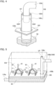
- the ventilation path VP in this embodiment is also provided near the tip end of the branch flow channel 109b and is a clearance between the branch flow channel 109b having a predetermined inner diameter and the tip end flow channel 109c having an inner diameter greater than that of the branch flow channel 109b. Additionally, the supply flow channel 109 is inserted in the flow channel through-hole 105b. Note that, the tip end flow channel 109c and the branch flow channel 109b are coupled to each other with coupling members 109X and 109Y. A clearance or the ventilation path VP still exists between the flow channel through-hole 105b and the tip end flow channel 109c.
- the support unit 105 can inhibit the nutrient solution 50 from splashing and adhering to the underground part of the plant 10. Consequently, it is possible to prevent the underground part of the plant 10 from being negatively affected by the adherence of the nutrient solution 50.
- a hydroponics device 100 of an embodiment 3 is described with reference to Fig. 5 .
- the hydroponics device 100 of this embodiment is different in the details described below from the above-described hydroponics device 100 of the embodiment 1.
- a ventilation path VP is positioned in the cultivation tank 106 and is a ventilation piping unit 109d provided in the branch flow channel 109b constituting the tip end portion of the supply flow channel 109.
- the ventilation piping unit 109d is a cylindrical portion extending from a bending portion of the branch flow channel 109b.
- Such a configuration can implement the ventilation path VP with an extremely simple configuration.
- the ventilation piping unit 109d as the ventilation path VP may be provided in any position in the branch flow channel 109b as long as the position is downstream of the flow amount adjustment unit 120.
- the ventilation piping unit 109d may be a through hole that penetrates through a part of a piping unit constituting the branch flow channel 109b.
- a hydroponics device 100 of an embodiment 4 is described with reference to Fig. 6 .
- the hydroponics device 100 of this embodiment is different in the details described below from the above-described hydroponics device 100 of the embodiment 1.
- the support unit 105 supporting the underground part of the plant 10 and having the root through-hole 105a penetrating therethrough to immerge the root 13 of the plant 10 in the nutrient solution 50 is provided in the cultivation tank 106.
- the support unit 105 includes the mount area X in which the underground part of the plant 10 is disposed and the hole surrounding area Y having the flow channel through-hole 105b through which the supply flow channel 109 passes. The tip end portion of the supply flow channel 109 is inserted in the flow channel through-hole 105b downward from the above.
- a filter F is provided below the support unit 105 in the cultivation tank 106, and the filter F in plan view extends vertically to separate the side of the supply flow channel 109 from the side on which the root 13 of the plant 10 exists.
- the filter F inhibits a part of the plant 10 or the tissue of a part of the plant 10 fallen off the plant 10 from entering the inside of the supply flow channel 109 from the tip end opening of the supply flow channel 109. That is, each of a number of holes of the filter F has the size that allows the nutrient solution 50 to pass therethrough but does not allow a part of the plant 10 or the partial tissue of the plant 10 fallen off the plant 10 to pass therethrough.
- the hydroponics device 100 of this embodiment a part of the plant 10, which is, for example, the root 13, or the partial tissue of the plant 10 fallen off the plant 10 is inhibited from interfering with the flow of the nutrient solution 50 flowing out from the supply flow channel 109. Consequently, it is easier to stabilize the flow rate of the nutrient solution 50 flowing through the supply flow channel 109 that guides the nutrient solution 50 to the cultivation tank 106.
- at least the hole surrounding area Y is formed of a transparent material. This makes it easier to grasp the state of the tip end of the supply flow channel 109.
- the transparent hole surrounding area Y it is preferable for the transparent hole surrounding area Y to be formed as an independent member such that the hole surrounding area Y can be detached from the mount area X. This makes it easier to remove unnecessary foreign matters accumulated in the nutrient solution 50 near the tip end of the supply flow channel 109 and to clean up the periphery of the tip end of the supply flow channel 109.
- a hydroponics device 100 of an embodiment 5 is described with reference to Figs. 7 and 8 .
- the hydroponics device 100 of this embodiment is different in the details described below from the above-described hydroponics device 100 of the embodiment 1.
- the hole surrounding area Y and the mount area X are connected to each other by a hinge 105c.
- the hole surrounding area Y has a door structure with which the hole surrounding area Y can be opened and closed, by pivoting about a rotational axis of the hinge 105c, with respect to an area other than the hole surrounding area Y, which is, for example, the mount area X.
- the hydroponics device 100 of this embodiment is different in only this point from the hydroponics device 100 of the embodiment 4 illustrated in Fig. 6 .
- the hole surrounding area Y it is possible to allow the hole surrounding area Y to pivot with the mount area X fixed. It is possible to open a space near the bottom surface of the cultivation tank 106 below the hole surrounding area Y This makes it easier to remove unnecessary foreign matters accumulated near the tip end of the supply flow channel 109 and to clean up the periphery of the tip end of the supply flow channel 109. Note that, even with the door structure, it is preferable that the hole surrounding area Y be formed of a transparent material to grasp the state of the periphery of the tip end of the supply flow channel 109 easily.
Landscapes
- Life Sciences & Earth Sciences (AREA)
- Environmental Sciences (AREA)
- Hydroponics (AREA)
Claims (5)
- Hydroponikvorrichtung (100), aufweisend:einen Kultivierungstank (106), der einen Strömungskanal darstellt, durch den eine einer Pflanze (10) zuzuführende Nährlösung (50) fließt;einen Nährlösungstank (108), der die Nährlösung (50) vorhält;einen Zufuhrströmungskanal (109), der die Nährlösung (50) von dem Nährlösungstank (108) an den Kultivierungstank (106) leitet;einen Ausleitungsströmungskanal (110), der die Nährlösung (50) von dem Kultivierungstank (106) an den Nährlösungstank (108) leitet;eine Pumpe (107), welche die Nährlösung (50) zwischen dem Nährlösungstank (108) und dem Kultivierungstank (106) über den Zufuhrströmungskanal (109) und den Ausleitungsströmungskanal (110) zirkuliert,eine Stützeinheit (105), die in dem Kultivierungstank (106) vorgesehen ist und konfiguriert ist, einen unterirdischen Teil der Pflanze (10) zu stützen, wobeider Zufuhrströmungskanal (109) einen Belüftungspfad (VP) aufweist, der ermöglicht, dass ein externer Raum des Zufuhrströmungskanals (109) und ein innerer Raum des Zufuhrströmungskanals (109) miteinander kommunizieren, undder Belüftungspfad (VP) eine Schwankung einer Strömungsrate der Nährlösung (50) unterbindet, die von dem Zufuhrströmungskanal (109) in den Kultivierungstank (106) strömt,dadurch gekennzeichnet, dasseine Vielzahl von Kultivierungstanks (106) vorgesehen sind,der Zufuhrströmungskanal (109) einen Hauptströmungskanal (109a) und eine Vielzahl von Zweigströmungskanälen (109b) aufweist, die von dem Hauptströmungskanal (109a) abzweigen, um die Nährlösung (50) durch die Pumpe (107) aus dem Nährlösungstank (108) an jeden der Vielzahl von Kultivierungstanks (106) zu leiten,die Stützeinheit (105) ein Wurzeldurchgangsloch (105a) aufweist, das derart vorgesehen ist, dass die sich von der Pflanze (10) erstreckende Wurzel die Nährlösung (50) erreicht, und ein Strömungskanaldurchgangsloch (105b) aufweist, das derart vorgesehen ist, dass ein Spitzenendabschnitt des Zufuhrströmungskanals (109) darin eingesetzt ist,der Belüftungsweg (VP) an jedem Spitzenende der Vielzahl von Zweigströmungskanälen (109b) vorgesehen ist und ein Freiraum ist zwischen dem Zweigströmungskanal (109b) und einem Spitzenendströmungskanal (109c) mit einem Durchmesser, der größer ist als jener des Zweigströmungskanals (109b),der Zweigströmungskanal (109b) und der Spitzenendströmungskanal (109c) den Zufuhrströmungskanal (109) darstellen,der Spitzenendströmungskanal (109c), der den Spitzenendabschnitt des Zufuhrströmungskanals (109) darstellt, in das Strömungskanaldurchgangsloch (105b) eingeführt ist, undein unterer Endabschnitt des Spitzenendströmungskanals (109c) in die Nährlösung (50) eingeführt ist, wobei der untere Endabschnitt des Spitzenendströmungskanals (109c) in einem vorgegebenen Abstand von einer unteren Fläche des Kultivierungstanks (106) positioniert ist.
- Hydroponikvorrichtung (100) nach Anspruch 1, wobeidie Stützeinheit (105) einen Montagebereich (X) um das Wurzeldurchgangsloch (105a) herum sowie einen Lochumgebungsbereich (Y) um das Strömungskanaldurchgangsloch (105b) herum aufweist, undzumindest der Lochumgebungsbereich (Y) aus einem transparenten Material gebildet ist.
- Hydroponikvorrichtung (100) nach Anspruch 1, wobeidie Stützeinheit (105) einen Montagebereich (X) um das Wurzeldurchgangsloch (105a) herum sowie einen Lochumgebungsbereich (Y) um das Strömungskanaldurchgangsloch (105b) herum aufweist, undder Lochumgebungsbereich (Y) eine Türstruktur aufweist, mit welcher der Lochumgebungsbereich (Y) in Bezug auf einen anderen Bereich als den Lochumgebungsbereich (Y) öffenbar und schließbar ist.
- Hydroponikvorrichtung (100) nach einem der Ansprüche 1 bis 3, ferner aufweisend:
einen Filter (F) in dem Kultivierungstank (106), wobei der Filter (F) derart konfiguriert ist, dass er verhindert, dass ein Teil der Pflanze (10) oder ein Teilgewebe der Pflanze (10), das von der Pflanze (10) abgefallen ist, in den Zufuhrströmungskanal (109) von einer Spitzenendöffnung des Zufuhrströmungskanals (109) gelangt. - Hydroponikvorrichtung (100) nach einem der Ansprüche 1 bis 4, wobeider Zufuhrströmungskanal (109) eine Durchflussmengen-Einstelleinheit (120) aufweist, die konfiguriert ist, eine Durchflussmenge der durch den Zufuhrströmungskanal (109) fließenden Nährlösung (50) einzustellen, undder Belüftungsweg (VP) stromabwärts der Durchflussmengen-Einstelleinheit (120) in dem Zufuhrströmungskanal (109) vorgesehen ist.
Applications Claiming Priority (2)
| Application Number | Priority Date | Filing Date | Title |
|---|---|---|---|
| JP2017238260 | 2017-12-13 | ||
| PCT/JP2018/044830 WO2019116999A1 (ja) | 2017-12-13 | 2018-12-06 | 水耕栽培装置 |
Publications (3)
| Publication Number | Publication Date |
|---|---|
| EP3725151A1 EP3725151A1 (de) | 2020-10-21 |
| EP3725151A4 EP3725151A4 (de) | 2021-01-27 |
| EP3725151B1 true EP3725151B1 (de) | 2023-05-10 |
Family
ID=66820019
Family Applications (1)
| Application Number | Title | Priority Date | Filing Date |
|---|---|---|---|
| EP18887413.5A Active EP3725151B1 (de) | 2017-12-13 | 2018-12-06 | Hydroponische vorrichtung |
Country Status (4)
| Country | Link |
|---|---|
| EP (1) | EP3725151B1 (de) |
| JP (1) | JP6970902B2 (de) |
| CN (1) | CN111491505B (de) |
| WO (1) | WO2019116999A1 (de) |
Families Citing this family (2)
| Publication number | Priority date | Publication date | Assignee | Title |
|---|---|---|---|---|
| CN111528095A (zh) * | 2020-06-03 | 2020-08-14 | 黎汉达 | 一种循环光照式植物离体培养设备 |
| CN115956496B (zh) * | 2023-01-10 | 2024-08-16 | 四川中农木林森光生物科技有限公司 | 一种防止发霉过程的培育装置及方法 |
Family Cites Families (14)
| Publication number | Priority date | Publication date | Assignee | Title |
|---|---|---|---|---|
| US3868787A (en) * | 1971-12-29 | 1975-03-04 | Weingarten & Wong Enterprises | Apparatus for supporting hydroponically grown plants |
| JPS63127348U (de) * | 1987-02-10 | 1988-08-19 | ||
| BE1005439A3 (fr) * | 1991-10-09 | 1993-07-27 | Julien Philippe | Dispositif d'injection des solutions nutritives pour cultures aero-hydroponiques. |
| EP2614882A1 (de) * | 2012-01-11 | 2013-07-17 | MIR Arastima ve Gelistime A.S. | Vorrichtung zur Belüftung von Wasser |
| CN202406643U (zh) * | 2012-02-21 | 2012-09-05 | 杨占生 | 红豆杉专用紫砂花盆 |
| CN103109708A (zh) * | 2013-02-05 | 2013-05-22 | 贵州省烟草科学研究院 | 保持烟叶大棚育苗水池恒温的加热装置 |
| JP2015096048A (ja) * | 2013-11-15 | 2015-05-21 | 三菱化学株式会社 | 生物体育成装置 |
| JP6172647B2 (ja) * | 2014-02-28 | 2017-08-02 | パナソニックIpマネジメント株式会社 | 水耕栽培装置とそれを用いた水耕栽培方法 |
| CN204259549U (zh) * | 2014-11-22 | 2015-04-15 | 毛吉贤 | 室内滴灌农作物灌溉装置 |
| JP6604465B2 (ja) * | 2014-12-24 | 2019-11-13 | パナソニックIpマネジメント株式会社 | 水耕栽培装置 |
| JP6919160B2 (ja) | 2015-08-05 | 2021-08-18 | 凸版印刷株式会社 | 栽培用容器、および、それを備える栽培システム |
| CN108366538B (zh) * | 2016-02-08 | 2020-06-16 | 松下知识产权经营株式会社 | 水培装置 |
| JP2017147970A (ja) * | 2016-02-24 | 2017-08-31 | パナソニックIpマネジメント株式会社 | 植物育成装置 |
| CN110505803A (zh) * | 2017-04-13 | 2019-11-26 | 松下知识产权经营株式会社 | 水耕栽培装置 |
-
2018
- 2018-12-06 EP EP18887413.5A patent/EP3725151B1/de active Active
- 2018-12-06 WO PCT/JP2018/044830 patent/WO2019116999A1/ja not_active Ceased
- 2018-12-06 JP JP2019559587A patent/JP6970902B2/ja not_active Expired - Fee Related
- 2018-12-06 CN CN201880080226.3A patent/CN111491505B/zh active Active
Also Published As
| Publication number | Publication date |
|---|---|
| CN111491505A (zh) | 2020-08-04 |
| JPWO2019116999A1 (ja) | 2020-12-03 |
| CN111491505B (zh) | 2022-03-04 |
| EP3725151A1 (de) | 2020-10-21 |
| EP3725151A4 (de) | 2021-01-27 |
| JP6970902B2 (ja) | 2021-11-24 |
| WO2019116999A1 (ja) | 2019-06-20 |
Similar Documents
| Publication | Publication Date | Title |
|---|---|---|
| US10004186B2 (en) | Hydroponic planting tower with horizontal grow platform | |
| KR101572372B1 (ko) | 빗물 자동공급 재배장치 | |
| KR101452278B1 (ko) | 분무경재배 시스템 | |
| EP3491911A1 (de) | Hydrokulturvorrichtung und hydrokulturverfahren | |
| EP3610719A1 (de) | Hydroponische kulturvorrichtung | |
| JP7397049B2 (ja) | 水耕栽培ユニット、及びこの水耕栽培ユニットを含む水耕栽培システム | |
| EP3725151B1 (de) | Hydroponische vorrichtung | |
| JP2018086004A (ja) | 無土壌植物栽培コンテナ | |
| US20150296725A1 (en) | Aeroponic and Drip Gardener System | |
| US20210037730A1 (en) | Hydroponic System Module | |
| JP6206802B2 (ja) | 水耕栽培装置 | |
| KR20100127144A (ko) | 모종 재배용 급수장치 | |
| KR20210034774A (ko) | 식물재배용 물 공급장치 | |
| JPH0532A (ja) | 水耕栽培装置 | |
| KR102403332B1 (ko) | 수위조절이 가능한 어항 및 화분의 재배장치 | |
| KR102036158B1 (ko) | 수경 재배 장치 | |
| KR102203079B1 (ko) | 다단식 자동 식물 재배 장치 | |
| KR102898453B1 (ko) | 통합 수경 재배 플랫폼 | |
| KR102691503B1 (ko) | 유량제어기능이 구비된 기내 배양통장치 | |
| KR102650045B1 (ko) | 스마트팜을 이용한 수경 재배 시스템 | |
| JP2002360072A (ja) | 植物栽培装置と植物栽培方法 | |
| JP2007236294A (ja) | 隔離床栽培用プランター | |
| KR20170104093A (ko) | 저면관수 시스템 | |
| JP5631718B2 (ja) | 栽培装置 | |
| JP2005102523A (ja) | 植物栽培容器への自動給水装置及び自動給水システム |
Legal Events
| Date | Code | Title | Description |
|---|---|---|---|
| STAA | Information on the status of an ep patent application or granted ep patent |
Free format text: STATUS: THE INTERNATIONAL PUBLICATION HAS BEEN MADE |
|
| PUAI | Public reference made under article 153(3) epc to a published international application that has entered the european phase |
Free format text: ORIGINAL CODE: 0009012 |
|
| STAA | Information on the status of an ep patent application or granted ep patent |
Free format text: STATUS: REQUEST FOR EXAMINATION WAS MADE |
|
| 17P | Request for examination filed |
Effective date: 20200618 |
|
| AK | Designated contracting states |
Kind code of ref document: A1 Designated state(s): AL AT BE BG CH CY CZ DE DK EE ES FI FR GB GR HR HU IE IS IT LI LT LU LV MC MK MT NL NO PL PT RO RS SE SI SK SM TR |
|
| AX | Request for extension of the european patent |
Extension state: BA ME |
|
| A4 | Supplementary search report drawn up and despatched |
Effective date: 20210112 |
|
| RIC1 | Information provided on ipc code assigned before grant |
Ipc: A01G 31/00 20180101ALN20201221BHEP Ipc: A01G 31/02 20060101AFI20201221BHEP Ipc: A01G 31/06 20060101ALI20201221BHEP |
|
| DAV | Request for validation of the european patent (deleted) | ||
| DAX | Request for extension of the european patent (deleted) | ||
| REG | Reference to a national code |
Ref country code: DE Ref legal event code: R079 Free format text: PREVIOUS MAIN CLASS: A01G0031000000 Ipc: A01G0031060000 Ref country code: DE Ref legal event code: R079 Ref document number: 602018049840 Country of ref document: DE Free format text: PREVIOUS MAIN CLASS: A01G0031000000 Ipc: A01G0031060000 |
|
| RIC1 | Information provided on ipc code assigned before grant |
Ipc: A01G 31/00 20180101ALN20221209BHEP Ipc: A01G 31/02 20060101ALI20221209BHEP Ipc: A01G 31/06 20060101AFI20221209BHEP |
|
| GRAP | Despatch of communication of intention to grant a patent |
Free format text: ORIGINAL CODE: EPIDOSNIGR1 |
|
| STAA | Information on the status of an ep patent application or granted ep patent |
Free format text: STATUS: GRANT OF PATENT IS INTENDED |
|
| RIC1 | Information provided on ipc code assigned before grant |
Ipc: A01G 31/00 19680901ALN20230106BHEP Ipc: A01G 31/02 19680901ALI20230106BHEP Ipc: A01G 31/06 19950101AFI20230106BHEP |
|
| INTG | Intention to grant announced |
Effective date: 20230126 |
|
| GRAS | Grant fee paid |
Free format text: ORIGINAL CODE: EPIDOSNIGR3 |
|
| GRAA | (expected) grant |
Free format text: ORIGINAL CODE: 0009210 |
|
| STAA | Information on the status of an ep patent application or granted ep patent |
Free format text: STATUS: THE PATENT HAS BEEN GRANTED |
|
| AK | Designated contracting states |
Kind code of ref document: B1 Designated state(s): AL AT BE BG CH CY CZ DE DK EE ES FI FR GB GR HR HU IE IS IT LI LT LU LV MC MK MT NL NO PL PT RO RS SE SI SK SM TR |
|
| REG | Reference to a national code |
Ref country code: GB Ref legal event code: FG4D |
|
| REG | Reference to a national code |
Ref country code: AT Ref legal event code: REF Ref document number: 1565810 Country of ref document: AT Kind code of ref document: T Effective date: 20230515 Ref country code: CH Ref legal event code: EP |
|
| REG | Reference to a national code |
Ref country code: DE Ref legal event code: R096 Ref document number: 602018049840 Country of ref document: DE |
|
| REG | Reference to a national code |
Ref country code: NL Ref legal event code: FP Ref country code: IE Ref legal event code: FG4D |
|
| REG | Reference to a national code |
Ref country code: LT Ref legal event code: MG9D |
|
| REG | Reference to a national code |
Ref country code: NL Ref legal event code: PD Owner name: FUJII & SONS., LTD.; JP Free format text: DETAILS ASSIGNMENT: CHANGE OF OWNER(S), ASSIGNMENT; FORMER OWNER NAME: PANASONIC INTELLECTUAL PROPERTY MANAGEMENT CO., LTD. Effective date: 20230919 |
|
| REG | Reference to a national code |
Ref country code: AT Ref legal event code: MK05 Ref document number: 1565810 Country of ref document: AT Kind code of ref document: T Effective date: 20230510 |
|
| PG25 | Lapsed in a contracting state [announced via postgrant information from national office to epo] |
Ref country code: SE Free format text: LAPSE BECAUSE OF FAILURE TO SUBMIT A TRANSLATION OF THE DESCRIPTION OR TO PAY THE FEE WITHIN THE PRESCRIBED TIME-LIMIT Effective date: 20230510 Ref country code: PT Free format text: LAPSE BECAUSE OF FAILURE TO SUBMIT A TRANSLATION OF THE DESCRIPTION OR TO PAY THE FEE WITHIN THE PRESCRIBED TIME-LIMIT Effective date: 20230911 Ref country code: NO Free format text: LAPSE BECAUSE OF FAILURE TO SUBMIT A TRANSLATION OF THE DESCRIPTION OR TO PAY THE FEE WITHIN THE PRESCRIBED TIME-LIMIT Effective date: 20230810 Ref country code: ES Free format text: LAPSE BECAUSE OF FAILURE TO SUBMIT A TRANSLATION OF THE DESCRIPTION OR TO PAY THE FEE WITHIN THE PRESCRIBED TIME-LIMIT Effective date: 20230510 Ref country code: AT Free format text: LAPSE BECAUSE OF FAILURE TO SUBMIT A TRANSLATION OF THE DESCRIPTION OR TO PAY THE FEE WITHIN THE PRESCRIBED TIME-LIMIT Effective date: 20230510 |
|
| PG25 | Lapsed in a contracting state [announced via postgrant information from national office to epo] |
Ref country code: RS Free format text: LAPSE BECAUSE OF FAILURE TO SUBMIT A TRANSLATION OF THE DESCRIPTION OR TO PAY THE FEE WITHIN THE PRESCRIBED TIME-LIMIT Effective date: 20230510 Ref country code: PL Free format text: LAPSE BECAUSE OF FAILURE TO SUBMIT A TRANSLATION OF THE DESCRIPTION OR TO PAY THE FEE WITHIN THE PRESCRIBED TIME-LIMIT Effective date: 20230510 Ref country code: LV Free format text: LAPSE BECAUSE OF FAILURE TO SUBMIT A TRANSLATION OF THE DESCRIPTION OR TO PAY THE FEE WITHIN THE PRESCRIBED TIME-LIMIT Effective date: 20230510 Ref country code: LT Free format text: LAPSE BECAUSE OF FAILURE TO SUBMIT A TRANSLATION OF THE DESCRIPTION OR TO PAY THE FEE WITHIN THE PRESCRIBED TIME-LIMIT Effective date: 20230510 Ref country code: IS Free format text: LAPSE BECAUSE OF FAILURE TO SUBMIT A TRANSLATION OF THE DESCRIPTION OR TO PAY THE FEE WITHIN THE PRESCRIBED TIME-LIMIT Effective date: 20230910 Ref country code: HR Free format text: LAPSE BECAUSE OF FAILURE TO SUBMIT A TRANSLATION OF THE DESCRIPTION OR TO PAY THE FEE WITHIN THE PRESCRIBED TIME-LIMIT Effective date: 20230510 Ref country code: GR Free format text: LAPSE BECAUSE OF FAILURE TO SUBMIT A TRANSLATION OF THE DESCRIPTION OR TO PAY THE FEE WITHIN THE PRESCRIBED TIME-LIMIT Effective date: 20230811 |
|
| PG25 | Lapsed in a contracting state [announced via postgrant information from national office to epo] |
Ref country code: FI Free format text: LAPSE BECAUSE OF FAILURE TO SUBMIT A TRANSLATION OF THE DESCRIPTION OR TO PAY THE FEE WITHIN THE PRESCRIBED TIME-LIMIT Effective date: 20230510 |
|
| PG25 | Lapsed in a contracting state [announced via postgrant information from national office to epo] |
Ref country code: SK Free format text: LAPSE BECAUSE OF FAILURE TO SUBMIT A TRANSLATION OF THE DESCRIPTION OR TO PAY THE FEE WITHIN THE PRESCRIBED TIME-LIMIT Effective date: 20230510 |
|
| PG25 | Lapsed in a contracting state [announced via postgrant information from national office to epo] |
Ref country code: SM Free format text: LAPSE BECAUSE OF FAILURE TO SUBMIT A TRANSLATION OF THE DESCRIPTION OR TO PAY THE FEE WITHIN THE PRESCRIBED TIME-LIMIT Effective date: 20230510 Ref country code: SK Free format text: LAPSE BECAUSE OF FAILURE TO SUBMIT A TRANSLATION OF THE DESCRIPTION OR TO PAY THE FEE WITHIN THE PRESCRIBED TIME-LIMIT Effective date: 20230510 Ref country code: RO Free format text: LAPSE BECAUSE OF FAILURE TO SUBMIT A TRANSLATION OF THE DESCRIPTION OR TO PAY THE FEE WITHIN THE PRESCRIBED TIME-LIMIT Effective date: 20230510 Ref country code: EE Free format text: LAPSE BECAUSE OF FAILURE TO SUBMIT A TRANSLATION OF THE DESCRIPTION OR TO PAY THE FEE WITHIN THE PRESCRIBED TIME-LIMIT Effective date: 20230510 Ref country code: DK Free format text: LAPSE BECAUSE OF FAILURE TO SUBMIT A TRANSLATION OF THE DESCRIPTION OR TO PAY THE FEE WITHIN THE PRESCRIBED TIME-LIMIT Effective date: 20230510 Ref country code: CZ Free format text: LAPSE BECAUSE OF FAILURE TO SUBMIT A TRANSLATION OF THE DESCRIPTION OR TO PAY THE FEE WITHIN THE PRESCRIBED TIME-LIMIT Effective date: 20230510 |
|
| REG | Reference to a national code |
Ref country code: DE Ref legal event code: R097 Ref document number: 602018049840 Country of ref document: DE |
|
| PLBE | No opposition filed within time limit |
Free format text: ORIGINAL CODE: 0009261 |
|
| STAA | Information on the status of an ep patent application or granted ep patent |
Free format text: STATUS: NO OPPOSITION FILED WITHIN TIME LIMIT |
|
| 26N | No opposition filed |
Effective date: 20240213 |
|
| PG25 | Lapsed in a contracting state [announced via postgrant information from national office to epo] |
Ref country code: SI Free format text: LAPSE BECAUSE OF FAILURE TO SUBMIT A TRANSLATION OF THE DESCRIPTION OR TO PAY THE FEE WITHIN THE PRESCRIBED TIME-LIMIT Effective date: 20230510 |
|
| PG25 | Lapsed in a contracting state [announced via postgrant information from national office to epo] |
Ref country code: SI Free format text: LAPSE BECAUSE OF FAILURE TO SUBMIT A TRANSLATION OF THE DESCRIPTION OR TO PAY THE FEE WITHIN THE PRESCRIBED TIME-LIMIT Effective date: 20230510 Ref country code: IT Free format text: LAPSE BECAUSE OF FAILURE TO SUBMIT A TRANSLATION OF THE DESCRIPTION OR TO PAY THE FEE WITHIN THE PRESCRIBED TIME-LIMIT Effective date: 20230510 |
|
| REG | Reference to a national code |
Ref country code: DE Ref legal event code: R119 Ref document number: 602018049840 Country of ref document: DE |
|
| REG | Reference to a national code |
Ref country code: CH Ref legal event code: PL |
|
| PG25 | Lapsed in a contracting state [announced via postgrant information from national office to epo] |
Ref country code: LU Free format text: LAPSE BECAUSE OF NON-PAYMENT OF DUE FEES Effective date: 20231206 |
|
| PG25 | Lapsed in a contracting state [announced via postgrant information from national office to epo] |
Ref country code: MC Free format text: LAPSE BECAUSE OF FAILURE TO SUBMIT A TRANSLATION OF THE DESCRIPTION OR TO PAY THE FEE WITHIN THE PRESCRIBED TIME-LIMIT Effective date: 20230510 |
|
| GBPC | Gb: european patent ceased through non-payment of renewal fee |
Effective date: 20231206 |
|
| REG | Reference to a national code |
Ref country code: BE Ref legal event code: MM Effective date: 20231231 |
|
| PG25 | Lapsed in a contracting state [announced via postgrant information from national office to epo] |
Ref country code: MC Free format text: LAPSE BECAUSE OF FAILURE TO SUBMIT A TRANSLATION OF THE DESCRIPTION OR TO PAY THE FEE WITHIN THE PRESCRIBED TIME-LIMIT Effective date: 20230510 Ref country code: LU Free format text: LAPSE BECAUSE OF NON-PAYMENT OF DUE FEES Effective date: 20231206 |
|
| REG | Reference to a national code |
Ref country code: IE Ref legal event code: MM4A |
|
| PG25 | Lapsed in a contracting state [announced via postgrant information from national office to epo] |
Ref country code: DE Free format text: LAPSE BECAUSE OF NON-PAYMENT OF DUE FEES Effective date: 20240702 Ref country code: IE Free format text: LAPSE BECAUSE OF NON-PAYMENT OF DUE FEES Effective date: 20231206 |
|
| PG25 | Lapsed in a contracting state [announced via postgrant information from national office to epo] |
Ref country code: GB Free format text: LAPSE BECAUSE OF NON-PAYMENT OF DUE FEES Effective date: 20231206 |
|
| PG25 | Lapsed in a contracting state [announced via postgrant information from national office to epo] |
Ref country code: BE Free format text: LAPSE BECAUSE OF NON-PAYMENT OF DUE FEES Effective date: 20231231 |
|
| PG25 | Lapsed in a contracting state [announced via postgrant information from national office to epo] |
Ref country code: FR Free format text: LAPSE BECAUSE OF NON-PAYMENT OF DUE FEES Effective date: 20231231 |
|
| PG25 | Lapsed in a contracting state [announced via postgrant information from national office to epo] |
Ref country code: CH Free format text: LAPSE BECAUSE OF NON-PAYMENT OF DUE FEES Effective date: 20231231 |
|
| PG25 | Lapsed in a contracting state [announced via postgrant information from national office to epo] |
Ref country code: IE Free format text: LAPSE BECAUSE OF NON-PAYMENT OF DUE FEES Effective date: 20231206 Ref country code: GB Free format text: LAPSE BECAUSE OF NON-PAYMENT OF DUE FEES Effective date: 20231206 Ref country code: FR Free format text: LAPSE BECAUSE OF NON-PAYMENT OF DUE FEES Effective date: 20231231 Ref country code: DE Free format text: LAPSE BECAUSE OF NON-PAYMENT OF DUE FEES Effective date: 20240702 Ref country code: CH Free format text: LAPSE BECAUSE OF NON-PAYMENT OF DUE FEES Effective date: 20231231 Ref country code: BE Free format text: LAPSE BECAUSE OF NON-PAYMENT OF DUE FEES Effective date: 20231231 |
|
| PG25 | Lapsed in a contracting state [announced via postgrant information from national office to epo] |
Ref country code: BG Free format text: LAPSE BECAUSE OF FAILURE TO SUBMIT A TRANSLATION OF THE DESCRIPTION OR TO PAY THE FEE WITHIN THE PRESCRIBED TIME-LIMIT Effective date: 20230510 |
|
| PG25 | Lapsed in a contracting state [announced via postgrant information from national office to epo] |
Ref country code: BG Free format text: LAPSE BECAUSE OF FAILURE TO SUBMIT A TRANSLATION OF THE DESCRIPTION OR TO PAY THE FEE WITHIN THE PRESCRIBED TIME-LIMIT Effective date: 20230510 |
|
| PGFP | Annual fee paid to national office [announced via postgrant information from national office to epo] |
Ref country code: NL Payment date: 20241217 Year of fee payment: 7 |
|
| PG25 | Lapsed in a contracting state [announced via postgrant information from national office to epo] |
Ref country code: CY Free format text: LAPSE BECAUSE OF FAILURE TO SUBMIT A TRANSLATION OF THE DESCRIPTION OR TO PAY THE FEE WITHIN THE PRESCRIBED TIME-LIMIT; INVALID AB INITIO Effective date: 20181206 |
|
| PG25 | Lapsed in a contracting state [announced via postgrant information from national office to epo] |
Ref country code: HU Free format text: LAPSE BECAUSE OF FAILURE TO SUBMIT A TRANSLATION OF THE DESCRIPTION OR TO PAY THE FEE WITHIN THE PRESCRIBED TIME-LIMIT; INVALID AB INITIO Effective date: 20181206 |
|
| PG25 | Lapsed in a contracting state [announced via postgrant information from national office to epo] |
Ref country code: TR Free format text: LAPSE BECAUSE OF FAILURE TO SUBMIT A TRANSLATION OF THE DESCRIPTION OR TO PAY THE FEE WITHIN THE PRESCRIBED TIME-LIMIT Effective date: 20230510 |