EP3725285A1 - Medizinischer glasbehälter und verfahren zur herstellung davon - Google Patents
Medizinischer glasbehälter und verfahren zur herstellung davon Download PDFInfo
- Publication number
- EP3725285A1 EP3725285A1 EP18887773.2A EP18887773A EP3725285A1 EP 3725285 A1 EP3725285 A1 EP 3725285A1 EP 18887773 A EP18887773 A EP 18887773A EP 3725285 A1 EP3725285 A1 EP 3725285A1
- Authority
- EP
- European Patent Office
- Prior art keywords
- glass container
- silicon
- coat
- medical
- fluorine
- Prior art date
- Legal status (The legal status is an assumption and is not a legal conclusion. Google has not performed a legal analysis and makes no representation as to the accuracy of the status listed.)
- Withdrawn
Links
- 239000011521 glass Substances 0.000 title claims abstract description 193
- 238000000034 method Methods 0.000 title claims abstract description 45
- 238000004519 manufacturing process Methods 0.000 title claims abstract description 26
- 229910052799 carbon Inorganic materials 0.000 claims abstract description 77
- OKTJSMMVPCPJKN-UHFFFAOYSA-N Carbon Chemical compound [C] OKTJSMMVPCPJKN-UHFFFAOYSA-N 0.000 claims abstract description 76
- 229910052710 silicon Inorganic materials 0.000 claims abstract description 52
- 239000010703 silicon Substances 0.000 claims abstract description 52
- 239000007789 gas Substances 0.000 claims description 117
- 229910052731 fluorine Inorganic materials 0.000 claims description 60
- 239000011737 fluorine Substances 0.000 claims description 60
- YCKRFDGAMUMZLT-UHFFFAOYSA-N Fluorine atom Chemical compound [F] YCKRFDGAMUMZLT-UHFFFAOYSA-N 0.000 claims description 52
- XUIMIQQOPSSXEZ-UHFFFAOYSA-N Silicon Chemical compound [Si] XUIMIQQOPSSXEZ-UHFFFAOYSA-N 0.000 claims description 51
- 239000004215 Carbon black (E152) Substances 0.000 claims description 42
- 229930195733 hydrocarbon Natural products 0.000 claims description 42
- 150000002430 hydrocarbons Chemical class 0.000 claims description 42
- HSFWRNGVRCDJHI-UHFFFAOYSA-N alpha-acetylene Natural products C#C HSFWRNGVRCDJHI-UHFFFAOYSA-N 0.000 claims description 16
- 229920001971 elastomer Polymers 0.000 claims description 16
- 239000000470 constituent Substances 0.000 claims description 15
- VNWKTOKETHGBQD-UHFFFAOYSA-N methane Chemical compound C VNWKTOKETHGBQD-UHFFFAOYSA-N 0.000 claims description 10
- 230000008569 process Effects 0.000 claims description 10
- 238000002834 transmittance Methods 0.000 claims description 9
- 125000001153 fluoro group Chemical group F* 0.000 claims description 8
- 238000003860 storage Methods 0.000 claims description 7
- 239000005388 borosilicate glass Substances 0.000 claims description 6
- MYMOFIZGZYHOMD-UHFFFAOYSA-N Dioxygen Chemical class O=O MYMOFIZGZYHOMD-UHFFFAOYSA-N 0.000 claims description 4
- 229910001882 dioxygen Inorganic materials 0.000 claims description 4
- 125000002534 ethynyl group Chemical group [H]C#C* 0.000 claims description 4
- 239000005354 aluminosilicate glass Substances 0.000 claims description 3
- 238000007496 glass forming Methods 0.000 claims description 3
- 239000005361 soda-lime glass Substances 0.000 claims description 3
- VYPSYNLAJGMNEJ-UHFFFAOYSA-N Silicium dioxide Chemical compound O=[Si]=O VYPSYNLAJGMNEJ-UHFFFAOYSA-N 0.000 abstract description 30
- 239000000463 material Substances 0.000 abstract description 12
- 238000010521 absorption reaction Methods 0.000 abstract description 9
- 239000003814 drug Substances 0.000 abstract description 8
- 102000004169 proteins and genes Human genes 0.000 abstract description 7
- 108090000623 proteins and genes Proteins 0.000 abstract description 7
- 239000000377 silicon dioxide Substances 0.000 abstract description 5
- 238000004220 aggregation Methods 0.000 abstract description 4
- 230000002776 aggregation Effects 0.000 abstract description 4
- 239000010408 film Substances 0.000 description 148
- 230000015572 biosynthetic process Effects 0.000 description 40
- 229910052814 silicon oxide Inorganic materials 0.000 description 20
- 229910052739 hydrogen Inorganic materials 0.000 description 19
- 239000001257 hydrogen Substances 0.000 description 19
- 239000000758 substrate Substances 0.000 description 14
- XLYOFNOQVPJJNP-UHFFFAOYSA-N water Substances O XLYOFNOQVPJJNP-UHFFFAOYSA-N 0.000 description 14
- UFHFLCQGNIYNRP-UHFFFAOYSA-N Hydrogen Chemical compound [H][H] UFHFLCQGNIYNRP-UHFFFAOYSA-N 0.000 description 13
- 238000012360 testing method Methods 0.000 description 12
- 238000007872 degassing Methods 0.000 description 11
- 239000000243 solution Substances 0.000 description 11
- 230000000052 comparative effect Effects 0.000 description 10
- 238000005259 measurement Methods 0.000 description 10
- 230000001954 sterilising effect Effects 0.000 description 10
- 238000004659 sterilization and disinfection Methods 0.000 description 10
- 238000004040 coloring Methods 0.000 description 9
- WMIYKQLTONQJES-UHFFFAOYSA-N hexafluoroethane Chemical compound FC(F)(F)C(F)(F)F WMIYKQLTONQJES-UHFFFAOYSA-N 0.000 description 9
- 239000011248 coating agent Substances 0.000 description 8
- 238000000576 coating method Methods 0.000 description 8
- 238000010586 diagram Methods 0.000 description 8
- 239000007788 liquid Substances 0.000 description 8
- 239000000203 mixture Substances 0.000 description 8
- XNGIFLGASWRNHJ-UHFFFAOYSA-N phthalic acid Chemical compound OC(=O)C1=CC=CC=C1C(O)=O XNGIFLGASWRNHJ-UHFFFAOYSA-N 0.000 description 8
- 238000010828 elution Methods 0.000 description 7
- 239000013618 particulate matter Substances 0.000 description 7
- -1 polypropylene Polymers 0.000 description 7
- 239000005871 repellent Substances 0.000 description 7
- QVGXLLKOCUKJST-UHFFFAOYSA-N atomic oxygen Chemical compound [O] QVGXLLKOCUKJST-UHFFFAOYSA-N 0.000 description 6
- 230000000694 effects Effects 0.000 description 6
- 150000002431 hydrogen Chemical class 0.000 description 6
- 229910052760 oxygen Inorganic materials 0.000 description 6
- 239000001301 oxygen Substances 0.000 description 6
- 108010071390 Serum Albumin Proteins 0.000 description 4
- 102000007562 Serum Albumin Human genes 0.000 description 4
- 229910052782 aluminium Inorganic materials 0.000 description 4
- XAGFODPZIPBFFR-UHFFFAOYSA-N aluminium Chemical compound [Al] XAGFODPZIPBFFR-UHFFFAOYSA-N 0.000 description 4
- 239000007864 aqueous solution Substances 0.000 description 4
- 239000007853 buffer solution Substances 0.000 description 4
- 229920001577 copolymer Polymers 0.000 description 4
- 230000008878 coupling Effects 0.000 description 4
- 238000010168 coupling process Methods 0.000 description 4
- 238000005859 coupling reaction Methods 0.000 description 4
- 229920001038 ethylene copolymer Polymers 0.000 description 4
- 238000009832 plasma treatment Methods 0.000 description 4
- 239000004033 plastic Substances 0.000 description 4
- 229920003023 plastic Polymers 0.000 description 4
- 239000011734 sodium Substances 0.000 description 4
- 238000001179 sorption measurement Methods 0.000 description 4
- BFKJFAAPBSQJPD-UHFFFAOYSA-N tetrafluoroethene Chemical group FC(F)=C(F)F BFKJFAAPBSQJPD-UHFFFAOYSA-N 0.000 description 4
- 108091003079 Bovine Serum Albumin Proteins 0.000 description 3
- 229910003481 amorphous carbon Inorganic materials 0.000 description 3
- 229940098773 bovine serum albumin Drugs 0.000 description 3
- 125000002915 carbonyl group Chemical group [*:2]C([*:1])=O 0.000 description 3
- 238000002347 injection Methods 0.000 description 3
- 239000007924 injection Substances 0.000 description 3
- NJPPVKZQTLUDBO-UHFFFAOYSA-N novaluron Chemical compound C1=C(Cl)C(OC(F)(F)C(OC(F)(F)F)F)=CC=C1NC(=O)NC(=O)C1=C(F)C=CC=C1F NJPPVKZQTLUDBO-UHFFFAOYSA-N 0.000 description 3
- 238000000623 plasma-assisted chemical vapour deposition Methods 0.000 description 3
- LIVNPJMFVYWSIS-UHFFFAOYSA-N silicon monoxide Chemical compound [Si-]#[O+] LIVNPJMFVYWSIS-UHFFFAOYSA-N 0.000 description 3
- 239000000126 substance Substances 0.000 description 3
- ZOXJGFHDIHLPTG-UHFFFAOYSA-N Boron Chemical compound [B] ZOXJGFHDIHLPTG-UHFFFAOYSA-N 0.000 description 2
- DGAQECJNVWCQMB-PUAWFVPOSA-M Ilexoside XXIX Chemical compound C[C@@H]1CC[C@@]2(CC[C@@]3(C(=CC[C@H]4[C@]3(CC[C@@H]5[C@@]4(CC[C@@H](C5(C)C)OS(=O)(=O)[O-])C)C)[C@@H]2[C@]1(C)O)C)C(=O)O[C@H]6[C@@H]([C@H]([C@@H]([C@H](O6)CO)O)O)O.[Na+] DGAQECJNVWCQMB-PUAWFVPOSA-M 0.000 description 2
- 239000002033 PVDF binder Substances 0.000 description 2
- ZLMJMSJWJFRBEC-UHFFFAOYSA-N Potassium Chemical compound [K] ZLMJMSJWJFRBEC-UHFFFAOYSA-N 0.000 description 2
- ATUOYWHBWRKTHZ-UHFFFAOYSA-N Propane Chemical compound CCC ATUOYWHBWRKTHZ-UHFFFAOYSA-N 0.000 description 2
- BOTDANWDWHJENH-UHFFFAOYSA-N Tetraethyl orthosilicate Chemical compound CCO[Si](OCC)(OCC)OCC BOTDANWDWHJENH-UHFFFAOYSA-N 0.000 description 2
- 230000005540 biological transmission Effects 0.000 description 2
- 229910052796 boron Inorganic materials 0.000 description 2
- 229920005549 butyl rubber Polymers 0.000 description 2
- UUAGAQFQZIEFAH-UHFFFAOYSA-N chlorotrifluoroethylene Chemical group FC(F)=C(F)Cl UUAGAQFQZIEFAH-UHFFFAOYSA-N 0.000 description 2
- 239000004020 conductor Substances 0.000 description 2
- 230000006837 decompression Effects 0.000 description 2
- 230000007547 defect Effects 0.000 description 2
- 230000032798 delamination Effects 0.000 description 2
- 239000003989 dielectric material Substances 0.000 description 2
- 238000011156 evaluation Methods 0.000 description 2
- UQEAIHBTYFGYIE-UHFFFAOYSA-N hexamethyldisiloxane Chemical compound C[Si](C)(C)O[Si](C)(C)C UQEAIHBTYFGYIE-UHFFFAOYSA-N 0.000 description 2
- 230000006872 improvement Effects 0.000 description 2
- 229920003049 isoprene rubber Polymers 0.000 description 2
- 229910021645 metal ion Inorganic materials 0.000 description 2
- 239000002245 particle Substances 0.000 description 2
- 238000005268 plasma chemical vapour deposition Methods 0.000 description 2
- 229920002493 poly(chlorotrifluoroethylene) Polymers 0.000 description 2
- 239000005023 polychlorotrifluoroethylene (PCTFE) polymer Substances 0.000 description 2
- 229920002981 polyvinylidene fluoride Polymers 0.000 description 2
- 229910052700 potassium Inorganic materials 0.000 description 2
- 239000011591 potassium Substances 0.000 description 2
- 229910052708 sodium Inorganic materials 0.000 description 2
- 230000000087 stabilizing effect Effects 0.000 description 2
- LFQCEHFDDXELDD-UHFFFAOYSA-N tetramethyl orthosilicate Chemical compound CO[Si](OC)(OC)OC LFQCEHFDDXELDD-UHFFFAOYSA-N 0.000 description 2
- 229920002725 thermoplastic elastomer Polymers 0.000 description 2
- 239000010409 thin film Substances 0.000 description 2
- PQDJYEQOELDLCP-UHFFFAOYSA-N trimethylsilane Chemical compound C[SiH](C)C PQDJYEQOELDLCP-UHFFFAOYSA-N 0.000 description 2
- 229910021642 ultra pure water Inorganic materials 0.000 description 2
- 239000012498 ultrapure water Substances 0.000 description 2
- 241000792859 Enema Species 0.000 description 1
- VGGSQFUCUMXWEO-UHFFFAOYSA-N Ethene Chemical compound C=C VGGSQFUCUMXWEO-UHFFFAOYSA-N 0.000 description 1
- 239000005977 Ethylene Substances 0.000 description 1
- 239000004743 Polypropylene Substances 0.000 description 1
- 239000004793 Polystyrene Substances 0.000 description 1
- 239000003124 biologic agent Substances 0.000 description 1
- 238000011088 calibration curve Methods 0.000 description 1
- 150000001721 carbon Chemical group 0.000 description 1
- 125000003178 carboxy group Chemical group [H]OC(*)=O 0.000 description 1
- 239000000084 colloidal system Substances 0.000 description 1
- 238000005336 cracking Methods 0.000 description 1
- 239000007920 enema Substances 0.000 description 1
- 229940095399 enema Drugs 0.000 description 1
- 125000004435 hydrogen atom Chemical group [H]* 0.000 description 1
- 230000003301 hydrolyzing effect Effects 0.000 description 1
- 125000002887 hydroxy group Chemical group [H]O* 0.000 description 1
- 150000002500 ions Chemical class 0.000 description 1
- 125000000959 isobutyl group Chemical group [H]C([H])([H])C([H])(C([H])([H])[H])C([H])([H])* 0.000 description 1
- 238000012538 light obscuration Methods 0.000 description 1
- 229910052751 metal Inorganic materials 0.000 description 1
- 239000002184 metal Substances 0.000 description 1
- 238000012986 modification Methods 0.000 description 1
- 230000004048 modification Effects 0.000 description 1
- 238000012856 packing Methods 0.000 description 1
- 229920001155 polypropylene Polymers 0.000 description 1
- 229920002223 polystyrene Polymers 0.000 description 1
- 229940071643 prefilled syringe Drugs 0.000 description 1
- 239000001294 propane Substances 0.000 description 1
- 238000007789 sealing Methods 0.000 description 1
- 229920002379 silicone rubber Polymers 0.000 description 1
- 239000004945 silicone rubber Substances 0.000 description 1
- 229910001415 sodium ion Inorganic materials 0.000 description 1
Images



Classifications
-
- A—HUMAN NECESSITIES
- A61—MEDICAL OR VETERINARY SCIENCE; HYGIENE
- A61J—CONTAINERS SPECIALLY ADAPTED FOR MEDICAL OR PHARMACEUTICAL PURPOSES; DEVICES OR METHODS SPECIALLY ADAPTED FOR BRINGING PHARMACEUTICAL PRODUCTS INTO PARTICULAR PHYSICAL OR ADMINISTERING FORMS; DEVICES FOR ADMINISTERING FOOD OR MEDICINES ORALLY; BABY COMFORTERS; DEVICES FOR RECEIVING SPITTLE
- A61J1/00—Containers specially adapted for medical or pharmaceutical purposes
- A61J1/14—Details; Accessories therefor
- A61J1/1468—Containers characterised by specific material properties
-
- C—CHEMISTRY; METALLURGY
- C03—GLASS; MINERAL OR SLAG WOOL
- C03C—CHEMICAL COMPOSITION OF GLASSES, GLAZES OR VITREOUS ENAMELS; SURFACE TREATMENT OF GLASS; SURFACE TREATMENT OF FIBRES OR FILAMENTS MADE FROM GLASS, MINERALS OR SLAGS; JOINING GLASS TO GLASS OR OTHER MATERIALS
- C03C17/00—Surface treatment of glass, not in the form of fibres or filaments, by coating
- C03C17/34—Surface treatment of glass, not in the form of fibres or filaments, by coating with at least two coatings having different compositions
- C03C17/3411—Surface treatment of glass, not in the form of fibres or filaments, by coating with at least two coatings having different compositions with at least two coatings of inorganic materials
- C03C17/3429—Surface treatment of glass, not in the form of fibres or filaments, by coating with at least two coatings having different compositions with at least two coatings of inorganic materials at least one of the coatings being a non-oxide coating
- C03C17/3441—Surface treatment of glass, not in the form of fibres or filaments, by coating with at least two coatings having different compositions with at least two coatings of inorganic materials at least one of the coatings being a non-oxide coating comprising carbon, a carbide or oxycarbide
-
- A—HUMAN NECESSITIES
- A61—MEDICAL OR VETERINARY SCIENCE; HYGIENE
- A61J—CONTAINERS SPECIALLY ADAPTED FOR MEDICAL OR PHARMACEUTICAL PURPOSES; DEVICES OR METHODS SPECIALLY ADAPTED FOR BRINGING PHARMACEUTICAL PRODUCTS INTO PARTICULAR PHYSICAL OR ADMINISTERING FORMS; DEVICES FOR ADMINISTERING FOOD OR MEDICINES ORALLY; BABY COMFORTERS; DEVICES FOR RECEIVING SPITTLE
- A61J1/00—Containers specially adapted for medical or pharmaceutical purposes
- A61J1/05—Containers specially adapted for medical or pharmaceutical purposes for collecting, storing or administering blood, plasma or medical fluids ; Infusion or perfusion containers
- A61J1/06—Ampoules or carpules
- A61J1/065—Rigid ampoules, e.g. glass ampoules
-
- A—HUMAN NECESSITIES
- A61—MEDICAL OR VETERINARY SCIENCE; HYGIENE
- A61L—METHODS OR APPARATUS FOR STERILISING MATERIALS OR OBJECTS IN GENERAL; DISINFECTION, STERILISATION OR DEODORISATION OF AIR; CHEMICAL ASPECTS OF BANDAGES, DRESSINGS, ABSORBENT PADS OR SURGICAL ARTICLES; MATERIALS FOR BANDAGES, DRESSINGS, ABSORBENT PADS OR SURGICAL ARTICLES
- A61L31/00—Materials for other surgical articles, e.g. stents, stent-grafts, shunts, surgical drapes, guide wires, materials for adhesion prevention, occluding devices, surgical gloves, tissue fixation devices
- A61L31/08—Materials for coatings
- A61L31/10—Macromolecular materials
-
- A—HUMAN NECESSITIES
- A61—MEDICAL OR VETERINARY SCIENCE; HYGIENE
- A61M—DEVICES FOR INTRODUCING MEDIA INTO, OR ONTO, THE BODY; DEVICES FOR TRANSDUCING BODY MEDIA OR FOR TAKING MEDIA FROM THE BODY; DEVICES FOR PRODUCING OR ENDING SLEEP OR STUPOR
- A61M5/00—Devices for bringing media into the body in a subcutaneous, intra-vascular or intramuscular way; Accessories therefor, e.g. filling or cleaning devices, arm-rests
- A61M5/178—Syringes
- A61M5/28—Syringe ampoules or carpules, i.e. ampoules or carpules provided with a needle
-
- C—CHEMISTRY; METALLURGY
- C03—GLASS; MINERAL OR SLAG WOOL
- C03C—CHEMICAL COMPOSITION OF GLASSES, GLAZES OR VITREOUS ENAMELS; SURFACE TREATMENT OF GLASS; SURFACE TREATMENT OF FIBRES OR FILAMENTS MADE FROM GLASS, MINERALS OR SLAGS; JOINING GLASS TO GLASS OR OTHER MATERIALS
- C03C17/00—Surface treatment of glass, not in the form of fibres or filaments, by coating
- C03C17/001—General methods for coating; Devices therefor
- C03C17/003—General methods for coating; Devices therefor for hollow ware, e.g. containers
- C03C17/004—Coating the inside
-
- C—CHEMISTRY; METALLURGY
- C03—GLASS; MINERAL OR SLAG WOOL
- C03C—CHEMICAL COMPOSITION OF GLASSES, GLAZES OR VITREOUS ENAMELS; SURFACE TREATMENT OF GLASS; SURFACE TREATMENT OF FIBRES OR FILAMENTS MADE FROM GLASS, MINERALS OR SLAGS; JOINING GLASS TO GLASS OR OTHER MATERIALS
- C03C17/00—Surface treatment of glass, not in the form of fibres or filaments, by coating
- C03C17/22—Surface treatment of glass, not in the form of fibres or filaments, by coating with other inorganic material
-
- C—CHEMISTRY; METALLURGY
- C03—GLASS; MINERAL OR SLAG WOOL
- C03C—CHEMICAL COMPOSITION OF GLASSES, GLAZES OR VITREOUS ENAMELS; SURFACE TREATMENT OF GLASS; SURFACE TREATMENT OF FIBRES OR FILAMENTS MADE FROM GLASS, MINERALS OR SLAGS; JOINING GLASS TO GLASS OR OTHER MATERIALS
- C03C17/00—Surface treatment of glass, not in the form of fibres or filaments, by coating
- C03C17/34—Surface treatment of glass, not in the form of fibres or filaments, by coating with at least two coatings having different compositions
- C03C17/3411—Surface treatment of glass, not in the form of fibres or filaments, by coating with at least two coatings having different compositions with at least two coatings of inorganic materials
- C03C17/3429—Surface treatment of glass, not in the form of fibres or filaments, by coating with at least two coatings having different compositions with at least two coatings of inorganic materials at least one of the coatings being a non-oxide coating
- C03C17/3447—Surface treatment of glass, not in the form of fibres or filaments, by coating with at least two coatings having different compositions with at least two coatings of inorganic materials at least one of the coatings being a non-oxide coating comprising a halide
- C03C17/3452—Surface treatment of glass, not in the form of fibres or filaments, by coating with at least two coatings having different compositions with at least two coatings of inorganic materials at least one of the coatings being a non-oxide coating comprising a halide comprising a fluoride
-
- C—CHEMISTRY; METALLURGY
- C03—GLASS; MINERAL OR SLAG WOOL
- C03C—CHEMICAL COMPOSITION OF GLASSES, GLAZES OR VITREOUS ENAMELS; SURFACE TREATMENT OF GLASS; SURFACE TREATMENT OF FIBRES OR FILAMENTS MADE FROM GLASS, MINERALS OR SLAGS; JOINING GLASS TO GLASS OR OTHER MATERIALS
- C03C17/00—Surface treatment of glass, not in the form of fibres or filaments, by coating
- C03C17/34—Surface treatment of glass, not in the form of fibres or filaments, by coating with at least two coatings having different compositions
- C03C17/36—Surface treatment of glass, not in the form of fibres or filaments, by coating with at least two coatings having different compositions at least one coating being a metal
- C03C17/3602—Surface treatment of glass, not in the form of fibres or filaments, by coating with at least two coatings having different compositions at least one coating being a metal the metal being present as a layer
- C03C17/3621—Surface treatment of glass, not in the form of fibres or filaments, by coating with at least two coatings having different compositions at least one coating being a metal the metal being present as a layer one layer at least containing a fluoride
-
- C—CHEMISTRY; METALLURGY
- C03—GLASS; MINERAL OR SLAG WOOL
- C03C—CHEMICAL COMPOSITION OF GLASSES, GLAZES OR VITREOUS ENAMELS; SURFACE TREATMENT OF GLASS; SURFACE TREATMENT OF FIBRES OR FILAMENTS MADE FROM GLASS, MINERALS OR SLAGS; JOINING GLASS TO GLASS OR OTHER MATERIALS
- C03C17/00—Surface treatment of glass, not in the form of fibres or filaments, by coating
- C03C17/34—Surface treatment of glass, not in the form of fibres or filaments, by coating with at least two coatings having different compositions
- C03C17/42—Surface treatment of glass, not in the form of fibres or filaments, by coating with at least two coatings having different compositions at least one coating of an organic material and at least one non-metal coating
-
- A—HUMAN NECESSITIES
- A61—MEDICAL OR VETERINARY SCIENCE; HYGIENE
- A61M—DEVICES FOR INTRODUCING MEDIA INTO, OR ONTO, THE BODY; DEVICES FOR TRANSDUCING BODY MEDIA OR FOR TAKING MEDIA FROM THE BODY; DEVICES FOR PRODUCING OR ENDING SLEEP OR STUPOR
- A61M2205/00—General characteristics of the apparatus
- A61M2205/02—General characteristics of the apparatus characterised by a particular materials
- A61M2205/0238—General characteristics of the apparatus characterised by a particular materials the material being a coating or protective layer
-
- C—CHEMISTRY; METALLURGY
- C03—GLASS; MINERAL OR SLAG WOOL
- C03C—CHEMICAL COMPOSITION OF GLASSES, GLAZES OR VITREOUS ENAMELS; SURFACE TREATMENT OF GLASS; SURFACE TREATMENT OF FIBRES OR FILAMENTS MADE FROM GLASS, MINERALS OR SLAGS; JOINING GLASS TO GLASS OR OTHER MATERIALS
- C03C2217/00—Coatings on glass
- C03C2217/20—Materials for coating a single layer on glass
- C03C2217/28—Other inorganic materials
- C03C2217/282—Carbides, silicides
-
- C—CHEMISTRY; METALLURGY
- C03—GLASS; MINERAL OR SLAG WOOL
- C03C—CHEMICAL COMPOSITION OF GLASSES, GLAZES OR VITREOUS ENAMELS; SURFACE TREATMENT OF GLASS; SURFACE TREATMENT OF FIBRES OR FILAMENTS MADE FROM GLASS, MINERALS OR SLAGS; JOINING GLASS TO GLASS OR OTHER MATERIALS
- C03C2217/00—Coatings on glass
- C03C2217/20—Materials for coating a single layer on glass
- C03C2217/28—Other inorganic materials
- C03C2217/284—Halides
- C03C2217/285—Fluorides
-
- C—CHEMISTRY; METALLURGY
- C03—GLASS; MINERAL OR SLAG WOOL
- C03C—CHEMICAL COMPOSITION OF GLASSES, GLAZES OR VITREOUS ENAMELS; SURFACE TREATMENT OF GLASS; SURFACE TREATMENT OF FIBRES OR FILAMENTS MADE FROM GLASS, MINERALS OR SLAGS; JOINING GLASS TO GLASS OR OTHER MATERIALS
- C03C2217/00—Coatings on glass
- C03C2217/70—Properties of coatings
- C03C2217/75—Hydrophilic and oleophilic coatings
-
- C—CHEMISTRY; METALLURGY
- C03—GLASS; MINERAL OR SLAG WOOL
- C03C—CHEMICAL COMPOSITION OF GLASSES, GLAZES OR VITREOUS ENAMELS; SURFACE TREATMENT OF GLASS; SURFACE TREATMENT OF FIBRES OR FILAMENTS MADE FROM GLASS, MINERALS OR SLAGS; JOINING GLASS TO GLASS OR OTHER MATERIALS
- C03C2218/00—Methods for coating glass
- C03C2218/10—Deposition methods
- C03C2218/15—Deposition methods from the vapour phase
- C03C2218/152—Deposition methods from the vapour phase by cvd
- C03C2218/153—Deposition methods from the vapour phase by cvd by plasma-enhanced cvd
Definitions
- the present disclosure relates to a medical glass container, and more particularly, to a glass container for storing and preserving a medicine for medical purposes.
- the medical glass container includes, for example, a vial, an injector barrel (syringe), a syringe with needle, and a cartridge type syringe.
- Patent Document 1 A medical glass container that contains silicon, oxygen, carbon, hydrogen, and fluorine on the inner surface of the container and has an anti-adhesion coating formed by a plasma-enhanced chemical vapor deposition process has been disclosed (for example, see Patent Document 1).
- Patent Document 1 discloses that this anti-adhesion coating is amorphous and transparent, satisfies the pharmaceutical requirements, and has a wet contact angle with water of 80° or greater.
- Patent Document 2 discloses that this coating contains silicon, oxygen, carbon, and hydrogen, and is a low friction coating material for a plastic syringe.
- the container since the container has a water-repellent property, residual chemicals is easily removed.
- the anti-adhesion coating is a silicon-containing coat, and, considering Non-Patent Document 1, a glass container coated with a material having a composition different from that of this coat, that is, a glass container having a coat mainly consisting of carbon and hydrogen close to living-body components, is particularly desirable as biological agents containing living-body-derived substances have become popular in recent years.
- the silicon-containing coating material is not suitable for a glass syringe because it is formed for the purposes of improving lubricity, and its target is a plastic syringe. That is, the technique of Patent Document 2 is merely intended to reduce an extruding force of a plunger having a rubber gasket of a plastic syringe to the same level as that of the glass syringe. As prefilled syringes have become popular in recent years, a gasket having a high sealing property without leakage for a long period of time is demanded, and it is required to reduce the extruding force of the plunger in the glass syringe.
- an object of the present disclosure is to provide a medical glass container, in which a contact angle with an aqueous content is large, transparency is high, lubricity (slidability) is excellent, peeling of the silica component (SiO 2 ) of the glass, which is a base material of the container, does not easily occur, elution of a glass-derived component
- the object is to provide a medical glass container and a method for manufacturing the same, in which at least a part of a surface of the container is coated with a silicon-free diamond-like carbon film.
- a medical glass container according to the present invention has a coat formed on at least a part of an inner wall of a glass container, wherein the coat is a silicon-free diamond-like carbon film.
- the coat includes a silicon-free and fluorine-containing diamond-like carbon film or a silicon-free and fluorine-free diamond-like carbon film.
- a silicon-containing intermediate layer is provided between a glass surface of the inner wall of the glass container and the coat. Since the silicon-containing intermediate layer is provided, adhesion of the coat is improved, and transparency and heat resistance are improved.
- the glass surface of the inner wall of the glass container is hydrophilized. Since the glass surface of the inner wall of the glass container is hydrophilized, adhesion of the coat is improved.
- glass forming the glass container includes borosilicate glass, aluminosilicate glass, or soda lime glass.
- the glass container includes a vial, an injector barrel, a syringe with needle, and a cartridge type syringe.
- the glass container is a vial
- the medical glass container further has a rubber stopper, and at least a part of an inner surface of the rubber stopper is coated with a diamond-like carbon film or a fluororesin film.
- the content contained in the container does not come into contact with glass or rubber, but can come into contact with only the diamond-like carbon film or only both the diamond-like carbon film and the fluororesin film, so that stability of the content is improved.
- the glass container is an injector barrel
- the medical glass container further has a gasket-mounted plunger, and at least a part of a surface of the gasket is coated with a diamond-like carbon film. It is possible to smoothly move the plunger when it is pushed.
- the glass container is an injector barrel
- the medical glass container further has a gasket-mounted plunger
- a fluororesin film is bonded to at least a face of a surface of the gasket adjoining with the inner surface of the injector barrel. It is possible to smoothly move the plunger when it is pushed.
- the coat is a silicon-free and fluorine-containing diamond-like carbon film, and a transmittance of the glass container at 450 nm is 90 % or higher. It is possible to visually clearly recognize the content.
- a method for manufacturing a medical glass container having a coat formed on at least a part of an inner wall of the glass container wherein the method has a process of forming a silicon-free diamond-like carbon film as the coat by plasmatizing a hydrocarbon-based gas that does not contain silicon as a constituent element inside a storage space of the glass container.
- the hydrocarbon-based gas that does not contain silicon is a mixed gas of a first hydrocarbon-based gas that does not contain fluorine or silicon as a constituent element and a second hydrocarbon-based gas that is modified with fluorine and does not contain silicon as a constituent element, and the coat is a silicon-free/fluorine-containing diamond-like carbon film.
- the aforementioned mixed gas it is possible to easily set a desired ratio of the fluorine content in the coat.
- the hydrocarbon-based gas that does not contain silicon is a first hydrocarbon-based gas that does not contain fluorine or silicon as a constituent element, and the coat is a silicon-free/fluorine-containing diamond-like carbon film. It is possible to easily form the silicon-free/fluorine-free diamond-like carbon film.
- the first hydrocarbon-based gas is acetylene and/or methane.
- the aforementioned source gas it is possible to obtain a diamond-like carbon film having little coloring and excellent heat resistance.
- a gas volume ratio of the mixed gas satisfies a range of Formula 1. Since the fluorine content of the coat becomes within a predetermined range, for example, 8 to 50 atomic% (atomic percentage), an excellent water repellency effect is obtained.
- the hydrocarbon-based gas that does not contain silicon is plasmatized by high frequency output or microwave output.
- the source gas it is possible to easily plasmatize the source gas and form a coat having a high density on the inner surface of the container.
- the method further has a process of forming an intermediate layer on a glass surface of the inner wall of the glass container by plasmatizing a silicon-containing gas inside a storage space of the glass container before forming the silicon-free diamond-like carbon film as the coat.
- the method further has a hydrophilizing process for forming plasma by bringing a hydrocarbon-based gas or an oxygen gas modified with fluorine into contact with at least a part of an inner surface of the medical glass container before forming the coat and/or the intermediate layer. Since the glass surface of the inner wall of the glass container is hydrophilized, adhesion of the coat is improved, and transparency and heat resistance are improved.
- a medical glass container in which a contact angle with an aqueous content is large, transparency is high, lubricity (slidability) is excellent, peeling (delamination) of the silica component of the glass, which is a base material of the container, does not easily occur, elution of a glass-derived component (silicon, boron, sodium, potassium, or aluminum) into the content is negligible, aggregation (absorption) of protein, which is an effective component of a medicine, does not easily occur, there is heat resistance, and peeling of the coat is suppressed.
- a medical glass container and a method for manufacturing the same in which at least a part of the surface of the container is coated with a silicon-free diamond-like carbon film.
- the medical glass container according to the present embodiment has a coat formed on at least a part of the inner wall of the glass container, wherein the coat is a silicon-free diamond-like carbon film.
- the medical glass container includes a vial, an injector barrel, a syringe with needle, and a cartridge type syringe.
- the injector barrel includes a syringe with needle and a cartridge type syringe.
- Glass forming the glass container includes borosilicate glass, aluminosilicate glass, or soda lime glass.
- a coat 3 is formed on an inner wall 2a of the vial 2 at an area ratio of preferably 15% or higher, more preferably 30% or higher, and still more preferably 80% or higher. It is preferable that the coat 3 is formed on the entire bottom surface of the storage space of the vial. In addition, it is more preferable that the inner wall surface of the container lower than the center in height direction of the container h is formed on the entire surface. Furthermore, it is particularly preferable that the coat 3 is formed on the entire surface of the inner wall 2a of the glass container (vial 2).
- Peeling (delamination) of the silica component (SiO 2 component) of the glass, which is a base material of the vial 2 does not easily occur due to presence of the coat 3.
- peeling of silica tends to easily occur. However, this peeling can be suppressed.
- the glass container is the vial 2 and further has a rubber stopper 4, and at least a part of the inner surface of the rubber stopper 4 is preferably coated with a diamond-like carbon film 6 or a fluororesin film.
- the rubber stopper 4 is formed of thermoplastic elastomer, butyl rubber (isobutyl/isoprene rubber), silicone rubber, or the like. Since the medicine contained in the vial 2 can be brought into contact with only the diamond-like carbon film or with only both the diamond-like carbon film and the fluororesin film without contact with glass or rubber, stability of the content is improved.
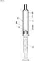
- a coat 22 is preferably formed on a surface where at least the glass container (injector barrel 21) and a gasket 24 installed in a plunger 23 can be brought into contact by sliding. Due to the presence of the coat 22, it is possible to improve lubricity, that is, slidability of the plunger 23, so that the plunger 23 can be smoothly moved when it is pushed. Furthermore, the coat 22 is preferably formed on the entire surface of the inner wall 21a of the injector barrel 21. In addition to improvement of slidability, the coat 22 prevents contact between a medicinal liquid which is the content and glass which is a constituent material of the injector barrel 21, and due to the coat 22 having high water-repellent property, residual liquid is reduced.
- the injector barrel 21 may be a prefilled syringe as well as a normal syringe.
- shape of the tip of the injector barrel is not particularly limited, and various shapes such as a luer slip type, a luer lock type, a luer metal type, a catheter tip type, and an enema type may be employed.
- the medical glass container 20 is an injector barrel, and further includes the plunger 23 in which the gasket 24 is installed, and at least a part of the surface 24a of the gasket 24 is preferably coated with the diamond-like carbon film 25.
- the diamond-like carbon film 25 is preferably formed on a portion of the surface of the gasket 24 that comes into contact with the inner surface 21a of the injector barrel 21.
- the diamond-like carbon film 25 formed on the surface of the gasket 24 and the inner surface of the glass container 20 (surface of the coat 22) come into contact with each other, so that the plunger 23 can be moved more smoothly when it is pushed.
- the diamond-like carbon film 25 is preferably formed on a portion of the surface of the gasket 24 that comes into contact with the medicine. In addition to improvement of slidability of the plunger 23, it is possible to prevent contact between the gasket 24 and the medicine. Furthermore, more preferably, the diamond-like carbon film 25 is formed on both a portion of the surface of the gasket 24 that comes into contact with the inner surface of the injector barrel and a portion that comes into contact with the medicine.
- the gasket 24 is formed of thermoplastic elastomer (such as butyl rubber or isoprene rubber), plastic (such as polypropylene or polystyrene), or the like.
- a fluororesin film 26 may be arranged instead of the diamond-like carbon film 25 formed on the surface of the gasket 24 illustrated in FIG. 2 . That is, in the medical glass container according to the present embodiment, it is preferable that the medical glass container 20 is an injector barrel, and further has the plunger 23 in which the gasket 24 is installed, and a fluororesin film 26 is bonded to at least a part of the surface 24a of the gasket 24 adjoining with the inner surface of the medical glass container 20 (the surface of the coat 22). It is possible to more smoothly move the plunger 23 when it is pushed.
- the fluororesin film may be formed of one or more fluororesins such as polytetrafluoroethylene, tetrafluoroethylene/perfluoroalkyl vinyl ether copolymer, tetrafluoroethylene/hexafluoropropylene copolymer, tetrafluoroethylene/ethylene copolymer, polyvinylidene fluoride, polychlorotrifluoroethylene, and chlorotrifluoroethylene/ethylene copolymer.
- fluororesins such as polytetrafluoroethylene, tetrafluoroethylene/perfluoroalkyl vinyl ether copolymer, tetrafluoroethylene/hexafluoropropylene copolymer, tetrafluoroethylene/ethylene copolymer, polyvinylidene fluoride, polychlorotrifluoroethylene, and chlorotrifluoroethylene/ethylene copolymer.
- the coats 3 and 22 are silicon-free diamond-like carbon films.
- the diamond-like carbon is also called a diamond-like carbon film, a DLC film, or an amorphous carbon film, and is a hydrogenated amorphous carbon film containing at least a carbon atom and a hydrogen atom.
- the coats 3 and 22 preferably have a thickness of 1 to 70 nm, and more preferably 2 to 10 nm. If the thickness is less than 1 nm, it may be difficult to form a uniform film without a defect. If the thickness exceeds 70 nm, peeling may occur, or coloring may exceed an allowable range.
- the coat 3 or 22 as a silicon-free diamond-like carbon film is a silicon-free and fluorine-containing diamond-like carbon film (hereinafter, referred to as "F-DLC film” in some cases) or a silicon-free and fluorine-free diamond-like carbon film (hereinafter, simply referred to as "DLC film” in some cases).
- F-DLC film silicon-free and fluorine-containing diamond-like carbon film
- DLC film silicon-free and fluorine-free diamond-like carbon film
- the fluorine-containing diamond-like carbon film is also called a fluorinated amorphous carbon film.
- the coat 3 or 22 is a silicon-free and fluorine-free diamond-like carbon film, the water-repellent property, the heat resistance, and the protein non-adsorption property are excellent.
- the fluorine content in the coat 3 or 22 is preferably 10 to 50 atomic% on the outermost surface of the coat. If the fluorine content is less than 10 atomic%, the act of the fluorine becomes less significant, and, for example, the water-repellent property and the transparency may decrease. If the fluorine content is more than 50 atomic%, the heat resistance may decrease.
- the fluorine content in the coat 3 or 22 is preferably in the range of 0 to 20 atomic% on the innermost surface of the coat in order to maintain adhesion. For this reason, the fluorine content preferably has a gradient composition that increases from the inner surface to the outermost surface of the coat.
- a silicon-containing intermediate layer is preferably provided between the glass surface of the inner wall and the coat of the glass container 2 or 21.
- the adhesion of the film is improved. Specifically, there are (1) a mode in which a silicon-containing intermediate layer is formed on the glass surface of the inner wall of the glass container 2 or 21, and a silicon-free and fluorine-free diamond-like carbon film is further formed thereon, and (2) a mode in which a silicon-containing intermediate layer is formed on the glass surface of the inner wall of the glass container 2 or 21, and a silicon-free and fluorine-containing diamond-like carbon film is further formed thereon.
- the silicon-containing intermediate layer is, for example, a silicon oxide film, and the silicon oxide film contains silicon, oxygen, carbon, and hydrogen, and has a thickness of 3 to 50 nm.
- the thickness of the silicon oxide film is more preferably 5 to 20 nm. If the thickness of the silicon oxide film is smaller than 3 nm, the act of the intermediate layer becomes less significant, and the adhesion of the coat provided on the intermediate layer may decrease.
- the silicon-free and fluorine-free diamond-like carbon film provided on the intermediate layer preferably has a density of 1.6 to 2.4 g/cm 3 , a hydrogen content of 8 to 40 atomic%, and a thickness of 1 to 70 nm.
- the density is more preferably 1.8 to 2.2 g/cm 3
- the hydrogen content is more preferably 10 to 30 atomic%
- the thickness is more preferably 2 to 10 nm. If the density is lower than 1.6 g/cm 3 , the heat resistance may decrease.
- the density is higher than 2.4 g/cm 3 , a crack may be generated, or coloring may become severe. If the hydrogen content is less than 8 atomic%, the density may increase, which may cause cracking or severe coloring. If the hydrogen content is more than 40 atomic%, the density may decrease, and the heat resistance may decrease. If the thickness is smaller than 1 nm, it may be difficult to uniformly form the film, and a defect may be generated in the coat. If the thickness is larger than 70 nm, the transparency may decrease.
- the silicon-containing intermediate layer is, for example, a silicon oxide film, and the silicon oxide film contains silicon, oxygen, carbon, and hydrogen, and may contain fluorine in some cases, and the thickness is 3 to 50 nm.
- the thickness of the silicon oxide film is more preferably 5 to 20 nm. If the thickness of the silicon oxide film is smaller than 3 nm, the act of the intermediate layer becomes less significant, so that the adhesion of the coat provided on the intermediate layer may decrease.
- the silicon-free and fluorine-containing diamond-like carbon film provided on the intermediate layer has a density of 1.6 to 2.4 g/cm 3 , a hydrogen content of 8 to 40 atomic%, an average fluorine content in the film of 10 to 20 atomic%, a fluorine content on the outermost surface of 8 to 50 atomic%, and a thickness of 1 to 70 nm.
- the density is 1.8 to 2.2 g/cm 3
- the hydrogen content is 10 to 30 atomic%
- the fluorine content on the outermost surface is 10 to 40 atomic%
- the thickness is 2 to 10 nm. If the density is lower than 1.6 g/cm 3 , the heat resistance may decrease. If the hydrogen content is less than 8 atomic%, the density may increase, a crack may be generated, or coloring may become severe. If the hydrogen content is more than 40 atomic%, the density may decrease, and the heat resistance may decrease. If the fluorine content is less than 8 atomic%, the act of the fluorine becomes less significant, and, for example, the water-repellent property and the transparency may decrease.
- the heat resistance may decrease. If the thickness is smaller than 1 nm, uniformity of film formation may be degraded. If the thickness is larger than 70 nm, peeling may occur, or coloring may exceed an allowable range.
- the intermediate layer and the silicon-free and fluorine-containing diamond-like carbon film may have a gradient composition, so that they may form a substantially single-layered gradient composition film.
- the outermost surface is a silicon-free and fluorine-containing diamond-like carbon surface
- the surface adjoining with the container inner surface is a silicon oxide surface or a fluorine-containing silicon oxide surface.
- the gradient composition film has a density of 1.6 to 2.4 g/cm 3 or preferably 1.8 to 2.2 g/cm 3 from the outermost surface to a thickness of 1 nm.
- the hydrogen content from the outermost surface to the thickness of 1 nm is 8 to 40 atomic% or preferably 10 to 30 atomic%.
- the fluorine content from the outermost surface to the thickness of 1 nm is 8 to 50 atomic% or preferably 10 to 40 atomic%.
- the surface of the silicon oxide adjoining with the inner surface of the container may contain silicon, oxygen, carbon, and hydrogen, and may contain fluorine.
- the composition gradually changes in the thickness direction of the coat from the surface adjoining with the inner surface of the container to the outermost surface, and the thickness of the coat 3 or 22 as the gradient composition film is 1 to 70 nm or preferably 5 to 20 nm.
- the heat resistance may decrease. If the density in the description (2) is less than 1.6 g/cm 3 , the heat resistance may decrease. If the density is higher than 2.4 g/cm 3 , a crack may occur, or coloring may become severe. If the hydrogen content is less than 8 atomic%, the density may decrease, and the heat resistance may decrease. If the hydrogen content is more than 40 atomic%, the density may increase, a crack may be generated, or coloring may become severe. If the fluorine content is less than 8 atomic%, the act of fluorine becomes less significant, and for example, the water-repellent property and the transparency may decrease. If the fluorine content is more than 50 atomic%, the heat resistance may decrease. If the thickness in the description (4) is smaller than 1 nm, uniformity of film formation may be degraded. If the thickness is larger than 70 nm, peeling may occur, or coloring may exceed an allowable range.
- At least a part of the glass surface of the inner wall of the glass container 2 or 21 is preferably hydrophilized in the mode in which the intermediate layer is provided.
- the hydrophilizing treatment for example, a carbonyl group or a carboxyl group may be added to the glass surface, or an OH group may be added or bonded.
- a layer containing a carbonyl group with a thickness of 0.5 to 10 nm is preferably formed at the interface between the intermediate layer and the inner surface of the container, and more preferably, a layer containing a carbonyl group with a thickness of 1 to 5 nm is formed.
- the silicon-containing intermediate layer is, for example, a silicon oxide film, and the silicon oxide film contains silicon, oxygen, carbon, and hydrogen, and may contain fluorine.
- the film thickness is more preferably 3 to 50 nm.
- the thickness of the silicon oxide film is more preferably 5 to 20 nm.
- the act of the intermediate layer becomes less significant, and adhesion of the coat provided on the intermediate layer may decrease. If the thickness of the silicon oxide film is larger than 50 nm, a crack may be generated due to internal stress, and it may take time for film formation.
- the diamond-like carbon film 6 formed on the surface of the rubber stopper 4 and the diamond-like carbon film 25 formed on the surface of the gasket 24 preferably contain hydrogen of 30 to 45 atomic% and fluorine of 0 to 20 atomic%, and has a thickness of preferably 1 to 70 nm or more preferably 5 to 20 nm.
- the fluororesin film that coats the surface of the rubber stopper 4 may be formed of one or more fluororesins such as polytetrafluoroethylene, tetrafluoroethylene/perfluoroalkyl vinyl ether copolymer, tetrafluoroethylene/hexafluoropropylene copolymer, tetrafluoroethylene/ethylene copolymer, polyvinylidene fluoride, polychlorotrifluoroethylene, or chlorotrifluoroethylene/ethylene copolymer.
- fluororesins such as polytetrafluoroethylene, tetrafluoroethylene/perfluoroalkyl vinyl ether copolymer, tetrafluoroethylene/hexafluoropropylene copolymer, tetrafluoroethylene/ethylene copolymer, polyvinylidene fluoride, polychlorotrifluoroethylene, or chlorotrifluoroethylene/ethylene copolymer.
- the medical glass container 1 or 20 preferably has a light-transmitting property. Specifically, the transmittance at a wavelength of 590 to 610 nm or 290 to 450 nm is preferably 45% or higher, or more preferably 60% or higher.
- An evaluation method for a transparency test is based on " Japanese Pharmacopoeia (17th Edition), 7 . Tests for Containers and Packing Materials, 7.01 Test for Glass Containers for Injections, (5) Light transmission test for light-resistant containers".
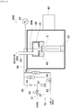
- FIG. 3 is a schematic diagram illustrating a high frequency type inner surface film formation apparatus for a vial.
- the high frequency type inner surface film formation apparatus 100 for a vial illustrated in FIG. 3 has source gas inlet lines 31, 32, and 33.
- Each source gas inlet line has a stop valve 34 and a gas flowmeter 35, and is connected to a single mixed-gas pipe 36.
- FIG. 3 illustrates a configuration in which three source gas inlet lines are provided, more source gas inlet lines may also be provided.
- the pipe 36 is connected to a conductive pipe 43a which also serves as an internal electrode and a gas introduction pipe arranged in a vacuum chamber 38.
- the vacuum chamber 38 is grounded, and a vacuum gauge 37 is connected thereto.
- a vial 2 an external electrode 45 arranged to surround a side surface and a bottom surface of the vial 2, a dielectric member 46 arranged to surround the external electrode 45, and an outer casing 48 that surrounds the dielectric member 46 and is formed of a conductive material for stabilizing plasma of the source gas are arranged.
- the vacuum chamber 38 is connected to a degassing pipe 49.
- the external electrode 45 is connected to an automatic matching device 40 so as not to be electrically connected to the vacuum chamber 38.
- the automatic matching device 40 is connected to a high frequency power supply 41.
- the high frequency is set to, for example, 1 to 100 MHz, or preferably 13.56 MHz.
- the source gas discharged from the conductive pipe 43a flows through the inside of the vial 2, is discharged from the tip opening thereof, passes through the space 48a provided in the upper side of the outer casing 48, and then reaches the internal space of the vacuum chamber 38. Then, the gas is discharged through the degassing pipe 49.
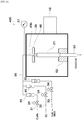
- FIG. 4 is a schematic diagram illustrating a microwave type inner surface film formation apparatus for a vial.
- the microwave type inner surface film formation apparatus 200 for a vial illustrated in FIG. 4 has source gas inlet lines 31, 32, and 33.
- Each source gas inlet line has a stop valve 34 and a gas flowmeter 35, and is connected to a single mixed-gas pipe 36.
- FIG. 4 illustrates a configuration in which three source gas inlet lines are provided, more source gas inlet lines may also be provided.
- the pipe 36 is connected to a gas introduction pipe 43b arranged in the microwave shield 39.
- a vacuum gauge 37 is connected to the pipe 36.
- a vial 2 inside the microwave shield 39, a vial 2, a dielectric member 46 for fixing an opening of the vial 2 to prevent gas leakage, a pedestal 52 formed of a dielectric material for loading the vial 2, a vacuum room 51, and a degassing pipe 50 connected to the vacuum room 51 are arranged.
- the opening of the vial 2 is connected to the space inside the vacuum room 51.
- the internal space of the vial 2 is also evacuated.
- a microwave oscillator 42 for outputting a microwave is provided inside the microwave shield 39.
- the microwave frequency is, for example, 0.9 to 45 GHz, or preferably 2.45 GHz.
- the source gas discharged from the tip opening of the gas introduction pipe 43b flows through the inside of the vial 2, is discharged from its opening, passes through the inside of the vacuum room 51, and is then discharged through the degassing pipe 49.
- FIG. 5 is a schematic diagram illustrating a high frequency type inner surface film formation apparatus for an injector barrel.
- the high frequency type inner surface film formation apparatus 300 for an injector barrel illustrated in FIG. 5 has source gas inlet lines 31, 32, and 33.
- Each source gas inlet line has a stop valve 34 and a gas flowmeter 35, and is connected to a single mixed-gas pipe 36.
- FIG. 5 illustrates a configuration in which three source gas inlet lines are provided, more source gas inlet lines may also be provided.
- the pipe 36 is connected to a gas introduction pipe 43c arranged inside a vacuum chamber 38.
- the vacuum chamber 38 is grounded, and a vacuum gauge 37 is connected thereto.
- an injector barrel 21, an external electrode 45 arranged to surround the injector barrel 21, a dielectric member 46 arranged to surround the external electrode 45, and an outer casing 48 arranged to surround the dielectric member 46 and formed of a conductive material for stabilizing plasma of the source gas are arranged inside the vacuum chamber 38.
- the vacuum chamber 38 is connected to the degassing pipe 49.
- the external electrode 45 is connected to an automatic matching device 40 so as not to be electrically connected to the vacuum chamber 38.
- the automatic matching device 40 is connected to a high frequency power supply 41.
- the frequency of the high frequency wave is, for example, 1 to 100 MHz, or preferably 13.56 MHz.
- a tip portion of the gas introduction pipe 43c is connected to a coupling portion which is the tip portion of the injector barrel 21.
- the source gas is delivered from the tip opening of the gas introducing pipe 43c to the coupling portion which is the tip portion of the injector barrel 21, flows inside the injector barrel 21, is discharged from the opening in the flange side of the injector barrel 21, passes through the space 48a provided in the upper side of the outer casing 48, and then reaches the internal space of the vacuum chamber 38. Then, the gas is discharged through the degassing pipe 49.
- FIG. 6 is a schematic diagram illustrating a microwave type inner surface film formation apparatus for an injector barrel.
- the microwave type inner surface film formation apparatus 400 for an injector barrel illustrated in FIG. 6 has source gas inlet lines 31, 32, and 33.
- Each source gas inlet line has a stop valve 34 and a gas flowmeter 35, and is connected to a single mixed-gas pipe 36.
- FIG. 6 illustrates a configuration in which three source gas inlet lines are provided, more source gas inlet lines may also be provided.
- the pipe 36 is connected to a gas introduction pipe 43b arranged in the microwave shield 39.
- a vacuum gauge 37 is connected to the pipe 36.
- an injector barrel 21, a dielectric member 46 for fixing a coupling portion (opening) of the tip portion of the injector barrel 21, a pedestal 52 formed of a dielectric material for loading a flange side of the injector barrel 21, and a degassing pipe 50 connected to the opening of the flange side of the injector barrel 21 are arranged inside the microwave shield 39.
- the coupling portion (opening) of the tip portion of the injector barrel 21 and the tip opening of the gas introduction pipe 43b are connected so as to prevent leakage.
- the opening of the flange side of the injector barrel 21 is connected to the degassing pipe 50.
- a microwave oscillator 42 for outputting a microwave is provided inside the microwave shield 39.
- the microwave frequency is, for example, 0.9 to 45 GHz, or preferably 2.45 GHz.
- the source gas introduced from the tip opening of the gas introduction pipe 43b flows through the inside of the injector barrel 21, is discharged from the opening of the flange side, and is then discharged through the degassing pipe 49.
- a method for manufacturing a medical glass container according to the present embodiment is a method for manufacturing a medical glass container 1 or 20 having a coat 3 formed on at least a part of an inner wall of the medical glass container, the method including a process of forming a silicon-free diamond-like carbon film as the coat 3 by plasmatizing a silicon-free hydrocarbon-based gas as a constituent element inside a glass container, specifically inside a storage space of the vial 2 or the injector barrel 21.
- the silicon-free hydrocarbon-based gas includes a first hydrocarbon-based gas that does not contain fluorine or silicon as a constituent element (hereinafter, also referred to as "first hydrocarbon-based gas” in some cases), and a second hydrocarbon-based gas that is modified with fluorine and does not contain silicon as a constituent element (hereinafter, also referred to as "second hydrocarbon-based gas” in some cases).
- the first hydrocarbon-based gas includes, for example, acetylene, methane, ethylene, or propane, and acetylene or methane is preferable.
- the second hydrocarbon-based gas includes, for example, hexafluoroethane, C 6 F 10 (CF 3 ) 2 , and C 6 F 6 , and hexafluoroethane is preferable.
- plasmatization is performed by applying a high frequency wave or a microwave using the film formation apparatuses illustrated in FIGS. 3 to 6 .
- the silicon-free hydrocarbon-based gas is a mixed gas of the first hydrocarbon-based gas that does not contain fluorine or silicon as a constituent element and the second hydrocarbon-based gas that is modified with fluorine and does not contain silicon as a constituent element, and the coat is a silicon-free and fluorine-containing diamond-like carbon film.
- the fluorine content in the coat can be easily set to a desired ratio.
- the gas volume ratio of the mixed gas preferably satisfies a range of Formula 1.
- the fluorine content in the coat is within a predetermined range, for example, 8 to 50 atomic% (atomic percentage), and an excellent water repellency effect is obtained.
- the silicon-free hydrocarbon-based gas is the first hydrocarbon-based gas that does not contain fluorine or silicon as a constituent element, and the coat is a silicon-free and fluorine-free diamond-like carbon film. It is possible to easily form the silicon-free and fluorine-free diamond-like carbon film.
- a process of forming the intermediate layer on the glass surface of the inner wall of the vial 2 or the injector barrel 21 by plasmatizing the silicon-containing gas inside the storage space of the vial 2 or the injector barrel 21 is provided.
- the silicon-containing gas includes, for example, a mixed gas containing an oxygen gas and trimethylsilane (TrMS), hexamethyldisiloxane (HMDSO), tetramethylorthosilicate (Si(OCH 3 ) 4 ), or tetraethoxysilane (Si(OC 2 H 5 ) 4 ).
- TrMS trimethylsilane
- HMDSO hexamethyldisiloxane
- Si(OCH 3 ) 4 tetramethylorthosilicate
- Si(OC 2 H 5 ) 4 tetraethoxysilane
- the mixing ratio between the silicon-containing gas and the silicon-free hydrocarbon-based gas may be set to 100:0 at the beginning of film formation, may be changed as the film formation time progresses, and may be set to 0:100 at the end of film formation. In this case, the coat becomes a gradient composition film.
- a hydrophilizing process for forming plasma by bring a hydrocarbon-based gas or an oxygen gas modified with fluorine into contact with at least a part of the inner surface of the vial 2 or the injector barrel 21 is provided. Since the glass surface of the inner wall of the vial 2 or the injector barrel 21 is hydrophilized, adhesion of the coat and uniformity of the coat are improved, and the inner surface temperature at the time of the hydrophilizing treatment increases, so that there is an effect of increasing the density of the coat.
- the hydrocarbon-based gas modified with fluorine includes hexafluoroethane, C 6 F 10 (CF 3 ) 2 , and C 6 F 6 , and hexafluoroethane is preferable.
- Conditions for forming a film on a flat plate are as follows. Equipment: Parallel plate low-pressure plasma CVD apparatus High frequency output: 200 W, 13.56 MHz Initial decompression: 0.02 torr Film formation pressure: 0.1 torr Film formation time: As shown in the following table Mixed gas: As shown in the following table, where ratios indicate volume/flow-rate mixing ratio.
- Pretreatment None or O 2 plasma treatment for 5 min or C 2 F 6 plasma treatment for 5 min
- Base material Borosilicate glass substrate (having a length of 20 mm, a width of 20 mm, and a thickness of 0.1 mm) (denoted as glass in the table) or Si substrate (having a length of 20 mm, a width of 20 mm, and a thickness of 0.38 mm) (denoted as "Si" in the table))
- Thickness Step type thickness gauge (produced by DEKTAK XT, BRUKER)
- Contact angle The contact angle measurement device (DM300, produced by KYOWA) and pure water as an alternative to the aqueous content to be contacted were used. The measurement was performed by conforming to JIS R3257 "Testing method of wettability of glass substrate". Note that the aqueous content is a liquid chemical. Adhesion: Cross-cut test, JIS K 5600-5-6 (1999)
- the conditions for performing film formation on the inner surface of the container are as follows.
- Equipment Low pressure plasma CVD apparatus shown in FIG. 3 or 5 High frequency output: 100W, 13.56MHz
- Film formation time As shown in the following table
- Mixed gas As shown in the following table, where the ratios indicate volume/flow-rate mixing ratios
- Base material Borosilicate glass vial (having an outer diameter of 16 mm, an inner diameter of 14 mm, a height of 35 mm, and a volume of 2 ml) (in the table, referred to as "bottle”, and hereinafter, also referred to as "vial” in some cases), or an injector barrel (having an outer diameter of 12.3 mm, an inner diameter of 10.6 mm, a length of 60 mm, and a volume of 2 ml) (in the table, referred to as
- F-DLC An F-DLC film (hereinafter, referred to as "F-DLC" in the table) was deposited as a coat of the outermost layer. No intermediate layer was provided. The results are shown in Tables 1, 2, and 3.
- DLC DLC film
- No intermediate layer was provided.
- Table 4 Example B Substrate Outermost layer Pretreatment Gas Film formation time (sec.) Measured thickness (nm) Contact angle (°) 1 glass DLC none C 2 H 2 2 3.8 80.8 2 glass DLC none C2H2 5 9.5 80.5
- Example C Substrate Outermost layer Pretreatment Gas (for outermost/ for intermediate layer) Film formation time (sec.) (outermost/ intermediate layer) Measured thickness (nm) (outermost/ intermediate Contact angle (°) 1 glass DLC none C 2 H 2 /TrMS-O 2 (6:4) 2/3 3.8/4.3 81.1 2 glass DLC none C 2 H 2 /TrMS-O 2 (6:4) 2/7 4.1/10.2 80.6 3 glass DLC none C 2 H 2 /TrMS-O 2 (6:4) 2/10 3.7/14.8 82.6
- Example D Substrate Outermost layer Pretreatment Gas (uppermost layer) or (for outermost/ for intermediate layer) Film formation time (sec.) (uppermost layer) or (for outermost/ for intermediate layer) Measured thickness (nm) (uppermost layer) or (for outermost/ for intermediate layer) Contact angle (°) 1 glass DLC none C 2 H 2 2 4.1 70.9 2 glass DLC O 2 C 2 H 2 2 3.9 70.6 3 glass DLC C 2 F 6 C 2 H 2 2 4.0 81.6 4 glass DLC none C 2 H 2 / TrMS-O 2 (6:4) 2/2 3.8/3.1 77.4 5 glass DLC 02 C 2 H 2 / TrMS-O 2 (6:4) 2/2 4.0/2.9 70.9 6 glass DLC C2F6 C 2 H 2 /
- a DLC film or an F-DLC film was formed as a coat of the outermost layer for Examples E-1 and E-2.
- a glass substrate having no coat in the outermost layer was employed.
- the measurement was performed in accordance with "JP17, 7.01 Test for Glass Containers for Injections, (5) Light transmission test for light-resistant container”. Specifically, it was performed as follows. Absorption at a wavelength of 290 to 810 nm was measured using an ultraviolet/visible spectrophotometer (ASUV6300PC, produced by AS ONE corporation).
- ASUV6300PC ultraviolet/visible spectrophotometer
- Example E Substrate Outermost layer Pretreatment Gas (uppermost layer) Film formation time (sec.) Measured thickness (nm) Contact angle (°) Transmittance (%) 290nm/450nm/ 590nm/610nm 1 glass DLC none CH 4 40 10.5 83.8 44.28/87.52/ 91.33/91.59 2 glass F-DLC none CH 4 /C 2 F 6 (2:8) 40 26.2 97.0 46.17/92.13/ 93.15/93.17 [Table 8] Comparative Example E Substrate Outermost layer Pretreatment Gas (uppermost layer) Film formation time (sec.) Measured thickness (nm) Contact angle (°) Transmittance (%) 290nm/450nm/ 590nm/610n
- a DLC film equivalent to that of Example E-1 or an F-DLC film equivalent to that of Example E-2 was formed on the inner wall of the medical glass container (vial having an outer diameter of 23 mm, an inner diameter of 21 mm, a height of 35 mm, and a volume of 5 ml, hereafter referred to as "vial 2") as a coat of the outermost layer in Examples F-1 and F-2.
- a medical glass container (vial 2) having no coat on the outermost layer was prepared.
- the remaining amount of water was measured as follows. Masses of the vial 2, the rubber stopper, and the aluminum cap were measured (mass 1). Then, the vial 2 is filled with ultra pure water at about 50% of the full volume, the rubber stopper and the aluminum cap were covered with lids, and then the mass was measured (mass 2). Then, the syringe was pierced into the rubber stopper, and the vial was sucked up while being turned upside down and was then weighed (mass 3). Each mass was measured using an electronic balance (MSA224S100DI, produced by SARTORIUS). The remaining amount of water was obtained by subtracting the mass 1 from the mass 3.
- the coated vial 2 was washed with ultra pure water and was dried at the room temperature. Then, a BSA (bovine serum albumin) solution of 10 ug/mL was transferred to each dried vial 2 by 1 mL, the vial 2 was moved to come into contact with the whole solution, and the solution was left at rest for 10 minutes. Then, the BSA solution in each vial 2 was taken by 10 ug, the fluorescence at a wavelength of 470/570 nm was measured, and the adsorption amount was calculated from the calibration curve. For the measurement of fluorescence, a plate reader (EnSpire, produced by Perkin Elmer, Inc.) was used.
- Tables 9 and 10 show the measurement results for the remaining amount of water and the absorption amount of serum albumin.
- Example F Outermost layer Remaining amount of water (g) Absorption amount of serum albumin (ug/vial) 1 DLC 0.009 3.65 2 F-DLC 0.004 - [Table 10] Comparative example F Outermost layer Remaining amount of water (g) Absorption amount of serum albumin (ug/vial) 1 - 0.092 5.20
- ADLC film equivalent to that of Example E-1 was formed on the inner wall of the medical glass container (vial 2) as a coat of the outermost layer in Example G-1.
- a medical glass container (vial 2) having no coat of the outermost layer was employed.
- the measurement was performed in accordance with "JP17, 6.07 Insoluble Particulate Matter Test for Injections, 1. Method 1. Light Obscuration Particle Count Test”. Specifically, it was performed as follows. Each vial 2 was filled with various solutions by 90% of the full volume to obtain an extract liquid after the high-pressure steam sterilization at a temperature of 121°C for one hour. Then, the number of insoluble particulate matter in the extract liquid was measured using an in-liquid particle counter (KL-04, produced by RION Co., Ltd.).
- Tables 11 and 12 show the measurement results of the elution amount after steam sterilization and the number of insoluble particulate matter contained per 1 mL after steam sterilization.
Landscapes
- Chemical & Material Sciences (AREA)
- Health & Medical Sciences (AREA)
- Life Sciences & Earth Sciences (AREA)
- Engineering & Computer Science (AREA)
- Organic Chemistry (AREA)
- Materials Engineering (AREA)
- Geochemistry & Mineralogy (AREA)
- General Chemical & Material Sciences (AREA)
- Chemical Kinetics & Catalysis (AREA)
- Public Health (AREA)
- General Health & Medical Sciences (AREA)
- Animal Behavior & Ethology (AREA)
- Veterinary Medicine (AREA)
- Vascular Medicine (AREA)
- Hematology (AREA)
- Heart & Thoracic Surgery (AREA)
- Pharmacology & Pharmacy (AREA)
- Surgery (AREA)
- Epidemiology (AREA)
- Anesthesiology (AREA)
- Biomedical Technology (AREA)
- Medical Preparation Storing Or Oral Administration Devices (AREA)
- Infusion, Injection, And Reservoir Apparatuses (AREA)
- Details Of Rigid Or Semi-Rigid Containers (AREA)
- Surface Treatment Of Glass (AREA)
Applications Claiming Priority (3)
| Application Number | Priority Date | Filing Date | Title |
|---|---|---|---|
| JP2017240315 | 2017-12-15 | ||
| JP2018232949A JP2019107445A (ja) | 2017-12-15 | 2018-12-12 | 医療用ガラス容器及びその製造方法 |
| PCT/JP2018/045986 WO2019117267A1 (ja) | 2017-12-15 | 2018-12-13 | 医療用ガラス容器及びその製造方法 |
Publications (2)
| Publication Number | Publication Date |
|---|---|
| EP3725285A1 true EP3725285A1 (de) | 2020-10-21 |
| EP3725285A4 EP3725285A4 (de) | 2021-09-01 |
Family
ID=67178447
Family Applications (1)
| Application Number | Title | Priority Date | Filing Date |
|---|---|---|---|
| EP18887773.2A Withdrawn EP3725285A4 (de) | 2017-12-15 | 2018-12-13 | Medizinischer glasbehälter und verfahren zur herstellung davon |
Country Status (4)
| Country | Link |
|---|---|
| US (1) | US20210017070A1 (de) |
| EP (1) | EP3725285A4 (de) |
| JP (1) | JP2019107445A (de) |
| CN (1) | CN111479544A (de) |
Cited By (1)
| Publication number | Priority date | Publication date | Assignee | Title |
|---|---|---|---|---|
| EP4458723A4 (de) * | 2021-12-28 | 2025-11-05 | Dainippon Printing Co Ltd | Flüssigkeitshaltiger behälter, flüssigkeitshaltiger kombinierter behälter, behälter, stopfen und verfahren zur herstellung eines flüssigkeitshaltigen behälters |
Families Citing this family (4)
| Publication number | Priority date | Publication date | Assignee | Title |
|---|---|---|---|---|
| EP3771460B1 (de) * | 2019-08-01 | 2022-10-12 | SCHOTT Schweiz AG | Dead-end behälter und behältersvorrichtung mit dead-end behälter |
| WO2021042090A2 (en) * | 2020-11-27 | 2021-03-04 | Schott Ag | System for long time storage of pharmaceutical compositions at low temperatures |
| CN113443838A (zh) * | 2021-07-05 | 2021-09-28 | 广州市智芯禾科技有限责任公司 | 一种医用dlc薄膜玻璃及其制备方法 |
| IT202300015462A1 (it) * | 2023-07-24 | 2025-01-24 | Stevanato Group Spa | Produzione di contenitori di vetro |
Family Cites Families (24)
| Publication number | Priority date | Publication date | Assignee | Title |
|---|---|---|---|---|
| FR2592874B1 (fr) * | 1986-01-14 | 1990-08-03 | Centre Nat Rech Scient | Procede pour tremper un objet en verre ou vitreux et objet ainsi trempe |
| US5198263A (en) * | 1991-03-15 | 1993-03-30 | The United States Of America As Represented By The United States Department Of Energy | High rate chemical vapor deposition of carbon films using fluorinated gases |
| US6335086B1 (en) * | 1999-05-03 | 2002-01-01 | Guardian Industries Corporation | Hydrophobic coating including DLC on substrate |
| JP2001046361A (ja) * | 1999-08-13 | 2001-02-20 | Terumo Corp | 医療用容器 |
| JP2001190665A (ja) * | 2000-01-14 | 2001-07-17 | Terumo Corp | シリンジ |
| JP4481587B2 (ja) * | 2003-04-25 | 2010-06-16 | テルモ株式会社 | シリンジ |
| US20070207321A1 (en) * | 2004-03-30 | 2007-09-06 | Yoshinori Abe | Method For Treating Surface Of Material, Surface-Treated Material, Medical Material, And Medical Instrument |
| JP2007267877A (ja) * | 2006-03-30 | 2007-10-18 | Terumo Corp | 医療用容器 |
| JP4860455B2 (ja) * | 2006-12-21 | 2012-01-25 | 日東電工株式会社 | シリンジ用ガスケットとこれを用いたシリンジならびにガスケット用摺動フィルム |
| JP5172180B2 (ja) * | 2007-03-19 | 2013-03-27 | トーヨーエイテック株式会社 | Dlc膜の修飾方法及び、医療用材料、医療用器具の製造方法 |
| EP2468320B8 (de) * | 2009-08-17 | 2015-08-19 | Kawasumi Laboratories, Inc. | Medizinisches instrument und metallprodukt |
| JP5665409B2 (ja) * | 2010-08-06 | 2015-02-04 | 株式会社ジェイテクト | 被膜の成膜方法 |
| JP5649533B2 (ja) * | 2011-07-29 | 2015-01-07 | 株式会社都ローラー工業 | 基材への親水性dlc膜の成膜方法と親水性dlc成膜基材 |
| JP2013044623A (ja) * | 2011-08-24 | 2013-03-04 | Hitachi High-Technologies Corp | 分析装置用分注ノズル及びそれを搭載した分析装置 |
| KR20130104189A (ko) * | 2012-03-13 | 2013-09-25 | 씨제이제일제당 (주) | Si-DLC 박막을 갖는 식품용기 및 그의 제조방법 |
| US9034442B2 (en) * | 2012-11-30 | 2015-05-19 | Corning Incorporated | Strengthened borosilicate glass containers with improved damage tolerance |
| JP5536168B2 (ja) * | 2012-10-03 | 2014-07-02 | トーヨーエイテック株式会社 | 超親水性材料、医療用材料及び医療用器具 |
| EP2971228B1 (de) * | 2013-03-11 | 2023-06-21 | Si02 Medical Products, Inc. | Beschichtete verpackung |
| JP6238053B2 (ja) * | 2013-09-13 | 2017-11-29 | 株式会社ジェイテクト | 摺動部材 |
| JP6270266B2 (ja) * | 2014-02-19 | 2018-01-31 | 住友ゴム工業株式会社 | プレフィルドシリンジ用ガスケットおよびプレフィルドシリンジ |
| WO2016132562A1 (ja) * | 2015-02-18 | 2016-08-25 | 株式会社ユーテック | 撥水性高硬度膜、金型及び撥水性高硬度膜の製造方法 |
| WO2017030196A1 (ja) * | 2015-08-20 | 2017-02-23 | 東京エレクトロン株式会社 | 培養容器並びに該培養容器を使用した細胞培養方法及び細胞観察方法 |
| FR3043679B1 (fr) * | 2015-11-12 | 2021-07-23 | Aptar Stelmi Sas | Procede de traitement d'un element de conditionnement en elastomere, et element de conditionnement ainsi traite. |
| WO2017141969A1 (ja) * | 2016-02-16 | 2017-08-24 | 三菱瓦斯化学株式会社 | 多層容器およびその応用 |
-
2018
- 2018-12-12 JP JP2018232949A patent/JP2019107445A/ja active Pending
- 2018-12-13 CN CN201880080646.1A patent/CN111479544A/zh active Pending
- 2018-12-13 US US16/772,679 patent/US20210017070A1/en not_active Abandoned
- 2018-12-13 EP EP18887773.2A patent/EP3725285A4/de not_active Withdrawn
Cited By (1)
| Publication number | Priority date | Publication date | Assignee | Title |
|---|---|---|---|---|
| EP4458723A4 (de) * | 2021-12-28 | 2025-11-05 | Dainippon Printing Co Ltd | Flüssigkeitshaltiger behälter, flüssigkeitshaltiger kombinierter behälter, behälter, stopfen und verfahren zur herstellung eines flüssigkeitshaltigen behälters |
Also Published As
| Publication number | Publication date |
|---|---|
| US20210017070A1 (en) | 2021-01-21 |
| EP3725285A4 (de) | 2021-09-01 |
| JP2019107445A (ja) | 2019-07-04 |
| CN111479544A (zh) | 2020-07-31 |
Similar Documents
| Publication | Publication Date | Title |
|---|---|---|
| EP3725285A1 (de) | Medizinischer glasbehälter und verfahren zur herstellung davon | |
| US10537273B2 (en) | Syringe with PECVD lubricity layer | |
| US11123491B2 (en) | Cyclic olefin polymer vessels and vessel coating methods | |
| KR102003651B1 (ko) | 유기실리콘 전구체를 이용한 pecvd 코팅 | |
| US20230092958A1 (en) | Vessels, containers, and surfaces coated with water barrier coatings | |
| US8815325B2 (en) | Medicinal inhalation device | |
| KR102472240B1 (ko) | 코팅된 패키징 | |
| EP4001456A1 (de) | Pharmazeutische und andere verpackungen mit niedriger sauerstoffübertragungsrate | |
| US20190093226A1 (en) | Method for applying a pecvd lubricity layer with a moving gas inlet | |
| WO2019117267A1 (ja) | 医療用ガラス容器及びその製造方法 | |
| CA2761905C (en) | Outgassing method for inspecting a coated surface | |
| US20250145519A1 (en) | Coating film-attached glass, production method therefor, and modified glass substrate | |
| TW202248449A (zh) | 用於醫療包裝之系統及方法 | |
| CN119866387A (zh) | 用于药物制剂的封闭件、其制造方法及其制造旋转沉积设备 |
Legal Events
| Date | Code | Title | Description |
|---|---|---|---|
| STAA | Information on the status of an ep patent application or granted ep patent |
Free format text: STATUS: THE INTERNATIONAL PUBLICATION HAS BEEN MADE |
|
| PUAI | Public reference made under article 153(3) epc to a published international application that has entered the european phase |
Free format text: ORIGINAL CODE: 0009012 |
|
| STAA | Information on the status of an ep patent application or granted ep patent |
Free format text: STATUS: REQUEST FOR EXAMINATION WAS MADE |
|
| 17P | Request for examination filed |
Effective date: 20200610 |
|
| AK | Designated contracting states |
Kind code of ref document: A1 Designated state(s): AL AT BE BG CH CY CZ DE DK EE ES FI FR GB GR HR HU IE IS IT LI LT LU LV MC MK MT NL NO PL PT RO RS SE SI SK SM TR |
|
| AX | Request for extension of the european patent |
Extension state: BA ME |
|
| DAV | Request for validation of the european patent (deleted) | ||
| DAX | Request for extension of the european patent (deleted) | ||
| REG | Reference to a national code |
Ref country code: DE Ref legal event code: R079 Free format text: PREVIOUS MAIN CLASS: A61J0001050000 Ipc: C03C0017000000 |
|
| A4 | Supplementary search report drawn up and despatched |
Effective date: 20210803 |
|
| RIC1 | Information provided on ipc code assigned before grant |
Ipc: C03C 17/00 20060101AFI20210728BHEP Ipc: A61J 1/14 20060101ALI20210728BHEP Ipc: C03C 17/22 20060101ALN20210728BHEP Ipc: C03C 17/42 20060101ALN20210728BHEP Ipc: A61J 1/06 20060101ALN20210728BHEP |
|
| STAA | Information on the status of an ep patent application or granted ep patent |
Free format text: STATUS: EXAMINATION IS IN PROGRESS |
|
| 17Q | First examination report despatched |
Effective date: 20230131 |
|
| STAA | Information on the status of an ep patent application or granted ep patent |
Free format text: STATUS: THE APPLICATION IS DEEMED TO BE WITHDRAWN |
|
| 18D | Application deemed to be withdrawn |
Effective date: 20230613 |