EP3725468B1 - Boîte à outils à surface luminescente - Google Patents
Boîte à outils à surface luminescente Download PDFInfo
- Publication number
- EP3725468B1 EP3725468B1 EP19759985.5A EP19759985A EP3725468B1 EP 3725468 B1 EP3725468 B1 EP 3725468B1 EP 19759985 A EP19759985 A EP 19759985A EP 3725468 B1 EP3725468 B1 EP 3725468B1
- Authority
- EP
- European Patent Office
- Prior art keywords
- luminescent
- bodies
- toolbox
- handle
- accidental opening
- Prior art date
- Legal status (The legal status is an assumption and is not a legal conclusion. Google has not performed a legal analysis and makes no representation as to the accuracy of the status listed.)
- Active
Links
Images


Classifications
-
- B—PERFORMING OPERATIONS; TRANSPORTING
- B25—HAND TOOLS; PORTABLE POWER-DRIVEN TOOLS; MANIPULATORS
- B25H—WORKSHOP EQUIPMENT, e.g. FOR MARKING-OUT WORK; STORAGE MEANS FOR WORKSHOPS
- B25H3/00—Storage means or arrangements for workshops facilitating access to, or handling of, work tools or instruments
- B25H3/02—Boxes
- B25H3/021—Boxes comprising a number of connected storage elements
- B25H3/022—Boxes comprising a number of connected storage elements in fixed relationship
-
- F—MECHANICAL ENGINEERING; LIGHTING; HEATING; WEAPONS; BLASTING
- F21—LIGHTING
- F21V—FUNCTIONAL FEATURES OR DETAILS OF LIGHTING DEVICES OR SYSTEMS THEREOF; STRUCTURAL COMBINATIONS OF LIGHTING DEVICES WITH OTHER ARTICLES, NOT OTHERWISE PROVIDED FOR
- F21V33/00—Structural combinations of lighting devices with other articles, not otherwise provided for
- F21V33/008—Leisure, hobby or sport articles, e.g. toys, games or first-aid kits; Hand tools; Toolboxes
- F21V33/0084—Hand tools; Toolboxes
-
- B—PERFORMING OPERATIONS; TRANSPORTING
- B62—LAND VEHICLES FOR TRAVELLING OTHERWISE THAN ON RAILS
- B62B—HAND-PROPELLED VEHICLES, e.g. HAND CARTS OR PERAMBULATORS; SLEDGES
- B62B2202/00—Indexing codes relating to type or characteristics of transported articles
- B62B2202/48—Tools
Definitions
- the purpose of this specification is a toolset carry-box with a luminescent surface, whose main advantage lies in incorporating parts of its luminescent surface, which allows its user to locate it swiftly and easily, in conditions of poor visibility and/or allow other users to locate it in situations of identical visibility.
- toolboxes or tool holders are devised as receptacles to carry work tools or other related items (such as pegs, screws or similar) that allow their user (operator) to comfortably organize all the necessary elements to correctly carry out their work properly.
- work tools or other related items such as pegs, screws or similar
- Document US 2011/234059 A1 discloses a system and method for a toolbox that includes: a body configured to receive casters on a bottom portion of the body; a lid coupled to the body, the lid including a raised portion on a top exterior surface of the lid to facilitate stabilization of the toolbox in a stacked configuration with a second toolbox; a front door coupled to the body and substantially centered in a front side of the toolbox, wherein the front door is at least 2 feet by at least 2 feet in size; lifting elements coupled to an upper portion of the body on each side of the lid to facilitate lifting of the toolbox and also to facilitate stabilization of the toolbox in the stacked configuration; and skid components coupled to a lower portion of the body to facilitate lifting of the toolbox and also to facilitate stabilization of the toolbox in the stacked configuration.
- Document CN 104 029 186 B relates to a kind of multifunctional toolbox.
- This multifunctional tool box comprises casing, diagonal cutting pliers, screwdriver and connecting rod, casing comprises housing, middle cover and end cap and three make by transparent plastic material, middle cover is clamped between housing and end cap, shell inner surface offers the first groove for placing diagonal cutting pliers, for the second groove that placing screws is criticized, for placing the 3rd groove of connecting rod, the inner surface of end cap is embedded with magnetic sheath collet chuck and two magnetic screwdriver bits folder, magnetic sheath collet chuck offer a row sleeve hole and be all inserted with sleeve in each sleeve hole, each magnetic screwdriver bit folder all offers a row screwdriver bit hole and is all inserted with screwdriver bit in each screwdriver bit hole, in the middle part of external face, perspective board is installed, perspective board is embedded with three brand sticking blocks and three arc phosphor strips.
- This multifunctional toolbox has advantage
- a handheld tool carrying case includes at least one interior structuring unit having at least one interior structuring element, which is provided to delimit at least one inductive charge receiving region for at least one handheld tool battery.
- the interior structuring unit is configured to be combinable in a modular manner.
- Document US 2001/028561 A1 discloses a container or receptacle having luminosity for emergency or non-lighted conditions to illuminate the surfaces of such containers or receptacles in which to give them visibility in the absence of any light source.
- the container includes an upper lid section and a lower retaining section having an interior compartment for holding of materials, goods, products, tools, medical equipment or medicine therein.
- the upper lid section includes interior lid wall surfaces and exterior lid wall surfaces
- the lower retaining section includes interior retaining wall surfaces and exterior retaining wall surfaces.
- the interior lid wall surfaces and/or the exterior lid surfaces includes a luminescent coating thereon for providing luminosity and for affording visibility to the upper lid section in the absence of any other light source.
- the interior retaining wall surfaces and/or the exterior retaining wall surfaces includes a luminescent coating thereon for providing luminosity and for affording visibility to the lower retaining section in the absence of any other light source.
- the luminescent coating includes protective covering means for allowing an increased visibility of the luminescent coating, and for giving resistance to wear and impact of the luminescent coating on the wall surfaces of the container.
- Document CN 107 717 921 A discloses a kind of safe electric tool box, including casing and for opening and closing the electronic lock of casing, lid is hinged with casing, electronic lock is arranged on casing, electronic lock includes fingerprint lock, fingerprint acquisition device, memory and fingerprint verifying apparatus, and fingerprint verifying apparatus is connected with fingerprint acquisition device, memory and fingerprint lock, and the electric tool chamber of depression is provided with casing, the inner side of upper lid is provided with the annex hanger bracket of electric tool, and hanger bracket is provided with hook.
- the advantage of the invention is that the annex can of electric tool is suspended on the hook of hanger bracket, user using when can easily find, can also avoid the loss of electric tool annex; electronic lock is configured with casing, prevents the instrument in electric toolbox from losing, improves security: luminescent layer is provided with the inner surface of electric toolbox, accurately electric tool can also be found by the light of fluorescent material in the case of dark.
- Document US 2012/326406 A1 discloses an apparatus for transporting articles having at least one container module that includes a container top having a non-releasable connection portion and a storage container that is selectively non-releasably connected to the container top and/or at least one other storage container.
- the storage container includes an upper non-releasable connection portion and a lower non-releasable connection portion.
- the upper non-releasable connection portion is selectively non-releasably connected to 1) a lower non-releasable connection portion of the at least one other storage container or 2) the non-releasable connection portion of the container top.
- the lower non-releasable connection portion is selectively non-releasably connected to an upper non-releasable connection portion of the at least one other storage container.
- the container module also includes a latch that releasably connects the storage container to the at least one other storage container if positioned on the container top.
- a luminescent toolbox apparatus includes a toolbox and a luminescent device attached to the toolbox in order to provide luminescence.
- the luminescent device includes a driver, a sensor connected with the driver and a light source connected with the driver. The driver turns on the light source as it receives a signal from the sensor.
- the technical issue solved by this invention is to obtain a tool holder box with a part of its surface that is luminescent in nature, making it possible for its user to locate it easily in moments of poor visibility.
- This technical problem is solved with the luminescent surface toolbox of claim 1 which comprises a first body that houses in its inner section a second, third and fourth body, where, on the surface of these bodies there is a luminescent and reflective coating that allows viewing these bodies even in situations of poor visibility, and the bodies feature a surface area whose measurements coincide with the interior area of the first body to be properly lodged therein.
- the box recommended here will have several luminescent areas on its surface, in such a way that it can be located particularly at those times of the day when there is poor visibility, or on works where there is low visibility.
- the box proposed here will have a non-slip surface on its upper part, which will provide greater safety, turning this area into a safe space to deposit certain objects required for the work being carried out in question, and that could cause injuries of differing kinds if they accidentally fell on the operator or another person located in the working area. Or that, due to the physical characteristics of said element, it could shatter upon contact with the ground.
- the toolbox can be separated into its different bodies in such a way that the operator can lay out all those elements that are necessary to work quickly and safely. This means that the operator can carry out their tasks in a more streamlined manner, since it will limit the loss of time both in transport and in the collection of material, which will invariably result in lower labor costs that will affect the economic costs associated with the work performed.
- the proposed toolbox is intended for use both with bare hands and with gloves, which allows its user to operate with or without gloves whenever they have to move or access it.
- the toolbox advocated here is materialized in such a way that it can support up to a weight of 120 kilograms, which, at certain times, will allow a user weighing less than 120 kg to use it as a stool to access certain places, where they would otherwise be unable to reach, avoiding the use of step ladders.
- the toolbox fitted with a luminescent surface that forms the basis of this specification, is characterized in that it comprises a first body (1) that houses within it a second (2), third (3) and fourth (4) body, and where, the surface of these bodies (1, 2, 3, 4) has a luminescent and reflective coating (5) that allows for the viewing of said bodies (1, 2, 3, 4) even in situations of poor visibility. And whereby the bodies (2, 3, 4) will have a surface coinciding with the interior area of the first body (1) to be properly kept apart inside and in a safe way, thus avoiding possible movements.
- the first body (1) has on its side dual wheels (1a) with a luminescent coating, which together with an ergonomic telescopic handle (1b) located on the side opposite the wheels (1a), allows said body to be positioned (1) upright, in order to carry the toolbox comfortably.
- the first body (1) On its upper part, the first body (1) has a non-slip surface (1c) that facilitates the placement of various elements on said surface (1c) safely. Furthermore, it features a series of luminescent material safety locks (1d) that prevent accidental opening of the first body (1), thus increasing its safety features. Finally, the axes of the first body (1) will be made of a metallic material resistant to various loads, allowing for versatile use in any workplace.
- the cover (1e) of the first body (1) will incorporate a tape measure in both millimeters and inches that will serve to facilitate the operator in their tasks.
- the wheels (1a), with a luminescent coating will be made of high-safety rubber or another material with equivalent mechanical characteristics.
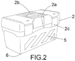
- the second body (2) will have in its upper part, a handle (2a) wholly devised in a luminescent material, and a non-slip surface (2b) that will prevent any object from sliding on its surface. Likewise, it will incorporate safety closures made of luminescent material (2c) that will prevent the accidental opening of the same.
- the third body (3) will be specially designed for use as a power tool housing, and therefore, it will have a protective foam coating inside, which will serve to ensure that the aforementioned power tool is correctly stored, thus increasing its working life.
- the third body (3) will incorporate safety closures made of luminescent material (3a) that will prevent the accidental opening of said third body (3), and a handle (3b) to facilitate its transportation.
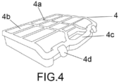
- the fourth body (4) will have a transparent upper surface, which will allow for its contents to be viewed so as to locate the small objects stored inside.
- a series of luminescent dividers (4a) will be fitted that split its interior into small housings (4b) and which, in turn, will make it easier to locate them.
- the fourth body (4) will incorporate a handle (4c) and safety closures made of luminescent material (4d) to prevent accidental opening.
- the bodies (1 and 2) come fitted on the under-section and bodies (3 and 4) on their lateral support part, with rubber plugs (6) or another material with equivalent mechanical characteristics, which improve their grip on the surface on which they are placed.
Landscapes
- Engineering & Computer Science (AREA)
- General Engineering & Computer Science (AREA)
- Mechanical Engineering (AREA)
- Packaging Of Annular Or Rod-Shaped Articles, Wearing Apparel, Cassettes, Or The Like (AREA)
- Illuminated Signs And Luminous Advertising (AREA)
Claims (4)
- Boîte à outils à surface luminescente qui comprend un premier corps (1) qui abrite à l'intérieur un deuxième (2), un troisième (3) et un quatrième (4) corps, et dans laquelle la surface de ces corps (1, 2, 3, 4) présente un revêtement luminescent et réfléchissant (5) qui permet de voir lesdits corps (1, 2, 3, 4) même dans des situations de mauvaise visibilité, et les deuxième, troisième et quatrième corps (2, 3, 4) présentent une surface dont les mesures coïncident avec la surface intérieure du premier corps (1) à loger correctement à l'intérieur, qui est caractérisé en ce quele premier corps (1) présente sur sa partie supérieure une surface antidérapante (1c) et une série de fermetures de sécurité en matériaux luminescents (1d) qui empêchent l'ouverture accidentelle du premier corps (1) ; et où les axes du premier corps sont en matériau métallique,le deuxième corps (2) comporte, sur sa partie supérieure, une poignée ajustée (2a) entièrement réalisée dans un matériau luminescent, et une surface antidérapante (2b) ; et, en outre, ledit deuxième corps (2) comporte des fermetures de sécurité en matériau luminescent (2c) qui empêchent son ouverture accidentelle ;et où le troisième corps (3) a un revêtement intérieur en mousse protectrice ; et incorpore une série de fermetures de sécurité en matériau luminescent (3a) qui empêcheront l'ouverture accidentelle dudit troisième corps (3) ainsi qu'une poignée (3b) pour faciliter son transport ;et dans lequel le quatrième corps (4) a une surface supérieure transparente et incorpore une poignée (4c) et des fermetures de sécurité en matière luminescente (4d) pour empêcher l'ouverture accidentelle ; et dans lequel, en outre, le quatrième corps (4) comporte une série de diviseurs luminescents (4a) qui divisent son intérieur en petits logements (4b).
- Boîte à outils à surface luminescente selon la revendication 1, dans laquelle le premier corps (1) a sur son côté deux roues (1a) avec un revêtement luminescent, qui ensemble avec une poignée télescopique (1b) située sur le côté opposé aux roues (1a) permettent audit corps (1) d'être positionné verticalement, et d'être transporté confortablement.
- Boîte à outils à surface luminescente selon l'une quelconque des revendications 1 à 2, le premier corps (1) comportant un couvercle (1e) incorporant un mètre ruban à la fois en millimètres et en pouces.
- Boîte à outils à surface luminescente selon l'une quelconque des revendications 1-2 où le premier et le deuxième corps (1 et 2) auront sur leur partie inférieure et le troisième et le quatrième corps (3 et 4) sur leur partie d'appui latérale, des picots en caoutchouc (6) qui améliorent leur adhérence sur la surface sur laquelle ils sont placés.
Applications Claiming Priority (2)
| Application Number | Priority Date | Filing Date | Title |
|---|---|---|---|
| ES201830267U ES1208037Y (es) | 2018-02-28 | 2018-02-28 | Caja portaherramientas con superficie luminiscente |
| PCT/ES2019/070029 WO2019166675A1 (fr) | 2018-02-28 | 2019-01-22 | Boîte à outils à surface luminescente |
Publications (4)
| Publication Number | Publication Date |
|---|---|
| EP3725468A1 EP3725468A1 (fr) | 2020-10-21 |
| EP3725468A4 EP3725468A4 (fr) | 2020-11-11 |
| EP3725468B1 true EP3725468B1 (fr) | 2023-06-07 |
| EP3725468C0 EP3725468C0 (fr) | 2023-06-07 |
Family
ID=61629049
Family Applications (1)
| Application Number | Title | Priority Date | Filing Date |
|---|---|---|---|
| EP19759985.5A Active EP3725468B1 (fr) | 2018-02-28 | 2019-01-22 | Boîte à outils à surface luminescente |
Country Status (5)
| Country | Link |
|---|---|
| US (1) | US20210229261A1 (fr) |
| EP (1) | EP3725468B1 (fr) |
| ES (2) | ES1208037Y (fr) |
| MA (1) | MA51168A (fr) |
| WO (1) | WO2019166675A1 (fr) |
Family Cites Families (13)
| Publication number | Priority date | Publication date | Assignee | Title |
|---|---|---|---|---|
| US6485159B2 (en) * | 1999-02-23 | 2002-11-26 | Algerome Pitts | Receptacles and containers having luminosity for non-lighted and emergency conditions |
| TWI222921B (en) * | 2003-05-14 | 2004-11-01 | Tai-Tzuo Chen | Tool storage apparatus with illumination structure |
| GB0326949D0 (en) * | 2003-11-19 | 2003-12-24 | Boyle Joseph C | Portable container |
| US8714355B2 (en) * | 2009-03-04 | 2014-05-06 | Stanley Black & Decker, Inc. | Integrated storage system with locking containers |
| US20110234059A1 (en) * | 2010-03-22 | 2011-09-29 | Ellerbe Ii James L | System and method for toolbox |
| CN201889788U (zh) * | 2010-10-08 | 2011-07-06 | 曹德生 | 一种新型电动工具箱 |
| CN202079586U (zh) * | 2011-05-25 | 2011-12-21 | 张翔 | 侧开式工具箱 |
| US8657307B2 (en) * | 2011-06-22 | 2014-02-25 | The Stanley Works Israel Ltd. | Modular rolling container assembly |
| DE102011086884A1 (de) * | 2011-11-22 | 2013-05-23 | Robert Bosch Gmbh | Handwerkzeugkoffer |
| CN104029186B (zh) * | 2014-04-29 | 2016-01-20 | 宁波市鄞州永佳电机工具有限公司 | 一种多功能工具箱 |
| CN205600683U (zh) * | 2016-05-18 | 2016-09-28 | 滨州学院 | 一种防止丢失的民航维修工具箱 |
| CN107351040A (zh) * | 2017-06-30 | 2017-11-17 | 王玲 | 一种便携式电梯安装工具箱 |
| CN107717921A (zh) * | 2017-10-28 | 2018-02-23 | 南通旭越光电科技有限公司 | 一种安全电动工具箱 |
-
2018
- 2018-02-28 ES ES201830267U patent/ES1208037Y/es not_active Expired - Fee Related
-
2019
- 2019-01-22 EP EP19759985.5A patent/EP3725468B1/fr active Active
- 2019-01-22 MA MA051168A patent/MA51168A/fr unknown
- 2019-01-22 WO PCT/ES2019/070029 patent/WO2019166675A1/fr not_active Ceased
- 2019-01-22 ES ES19759985T patent/ES2950795T3/es active Active
- 2019-01-22 US US16/959,464 patent/US20210229261A1/en not_active Abandoned
Also Published As
| Publication number | Publication date |
|---|---|
| WO2019166675A1 (fr) | 2019-09-06 |
| US20210229261A1 (en) | 2021-07-29 |
| EP3725468A4 (fr) | 2020-11-11 |
| ES2950795T3 (es) | 2023-10-13 |
| MA51168A (fr) | 2021-06-02 |
| EP3725468A1 (fr) | 2020-10-21 |
| ES1208037Y (es) | 2018-06-12 |
| EP3725468C0 (fr) | 2023-06-07 |
| ES1208037U (es) | 2018-03-22 |
Similar Documents
| Publication | Publication Date | Title |
|---|---|---|
| US12275558B2 (en) | Modular storage system with storage box connectivity and external box features and accessories | |
| US12533790B2 (en) | Tool storage devices | |
| TWI552840B (zh) | 具有偵測系統之容器 | |
| US4917281A (en) | Drill holster | |
| US9050992B2 (en) | Portable work station | |
| CA2813452C (fr) | Trousse pour scie cylindrique | |
| US10870195B2 (en) | Power tool with storage system | |
| EP3543203A1 (fr) | Ensemble de connexion | |
| GB2451957A (en) | Tool box with integrated inventory control system | |
| EP3725468B1 (fr) | Boîte à outils à surface luminescente | |
| US10220504B2 (en) | Portable drill ready stand and tool caddy | |
| US20240140510A1 (en) | Utility cart device | |
| US20250144785A1 (en) | Tool caddy | |
| US20090134050A1 (en) | Blade solution | |
| CN211167961U (zh) | 一种新型农具存储设备 | |
| CN215848094U (zh) | 一种用于电力检修的工具箱 | |
| CN216394274U (zh) | 一种护理用便携式工具箱 | |
| CN213540393U (zh) | 一种便于采矿使用的采矿锤 | |
| NZ751853A (en) | Connection Assembly | |
| KR20170066810A (ko) | 조명기능이 구비된 지질조사용 카트 | |
| GB2567832A (en) | Toolbox | |
| WO2019182675A1 (fr) | Appareil de protection de crayon et procédé d'utilisation | |
| GB2420309A (en) | Portable storage container and workbench |
Legal Events
| Date | Code | Title | Description |
|---|---|---|---|
| STAA | Information on the status of an ep patent application or granted ep patent |
Free format text: STATUS: THE INTERNATIONAL PUBLICATION HAS BEEN MADE |
|
| PUAI | Public reference made under article 153(3) epc to a published international application that has entered the european phase |
Free format text: ORIGINAL CODE: 0009012 |
|
| STAA | Information on the status of an ep patent application or granted ep patent |
Free format text: STATUS: REQUEST FOR EXAMINATION WAS MADE |
|
| 17P | Request for examination filed |
Effective date: 20200714 |
|
| AK | Designated contracting states |
Kind code of ref document: A1 Designated state(s): AL AT BE BG CH CY CZ DE DK EE ES FI FR GB GR HR HU IE IS IT LI LT LU LV MC MK MT NL NO PL PT RO RS SE SI SK SM TR |
|
| AX | Request for extension of the european patent |
Extension state: BA ME |
|
| STAA | Information on the status of an ep patent application or granted ep patent |
Free format text: STATUS: EXAMINATION IS IN PROGRESS |
|
| A4 | Supplementary search report drawn up and despatched |
Effective date: 20201012 |
|
| RIC1 | Information provided on ipc code assigned before grant |
Ipc: F21V 33/00 20060101ALI20201006BHEP Ipc: B25H 3/02 20060101AFI20201006BHEP |
|
| 17Q | First examination report despatched |
Effective date: 20201023 |
|
| DAX | Request for extension of the european patent (deleted) | ||
| RAV | Requested validation state of the european patent: fee paid |
Extension state: MA Effective date: 20200714 Extension state: TN Effective date: 20200714 |
|
| GRAP | Despatch of communication of intention to grant a patent |
Free format text: ORIGINAL CODE: EPIDOSNIGR1 |
|
| STAA | Information on the status of an ep patent application or granted ep patent |
Free format text: STATUS: GRANT OF PATENT IS INTENDED |
|
| INTG | Intention to grant announced |
Effective date: 20221024 |
|
| GRAS | Grant fee paid |
Free format text: ORIGINAL CODE: EPIDOSNIGR3 |
|
| GRAA | (expected) grant |
Free format text: ORIGINAL CODE: 0009210 |
|
| STAA | Information on the status of an ep patent application or granted ep patent |
Free format text: STATUS: THE PATENT HAS BEEN GRANTED |
|
| AK | Designated contracting states |
Kind code of ref document: B1 Designated state(s): AL AT BE BG CH CY CZ DE DK EE ES FI FR GB GR HR HU IE IS IT LI LT LU LV MC MK MT NL NO PL PT RO RS SE SI SK SM TR |
|
| REG | Reference to a national code |
Ref country code: GB Ref legal event code: FG4D |
|
| REG | Reference to a national code |
Ref country code: CH Ref legal event code: EP Ref country code: AT Ref legal event code: REF Ref document number: 1573589 Country of ref document: AT Kind code of ref document: T Effective date: 20230615 |
|
| REG | Reference to a national code |
Ref country code: DE Ref legal event code: R096 Ref document number: 602019030369 Country of ref document: DE |
|
| U01 | Request for unitary effect filed |
Effective date: 20230620 |
|
| U07 | Unitary effect registered |
Designated state(s): AT BE BG DE DK EE FI FR IT LT LU LV MT NL PT SE SI Effective date: 20230720 |
|
| REG | Reference to a national code |
Ref country code: LT Ref legal event code: MG9D |
|
| REG | Reference to a national code |
Ref country code: ES Ref legal event code: FG2A Ref document number: 2950795 Country of ref document: ES Kind code of ref document: T3 Effective date: 20231013 |
|
| PG25 | Lapsed in a contracting state [announced via postgrant information from national office to epo] |
Ref country code: NO Free format text: LAPSE BECAUSE OF FAILURE TO SUBMIT A TRANSLATION OF THE DESCRIPTION OR TO PAY THE FEE WITHIN THE PRESCRIBED TIME-LIMIT Effective date: 20230907 |
|
| PG25 | Lapsed in a contracting state [announced via postgrant information from national office to epo] |
Ref country code: RS Free format text: LAPSE BECAUSE OF FAILURE TO SUBMIT A TRANSLATION OF THE DESCRIPTION OR TO PAY THE FEE WITHIN THE PRESCRIBED TIME-LIMIT Effective date: 20230607 Ref country code: HR Free format text: LAPSE BECAUSE OF FAILURE TO SUBMIT A TRANSLATION OF THE DESCRIPTION OR TO PAY THE FEE WITHIN THE PRESCRIBED TIME-LIMIT Effective date: 20230607 Ref country code: GR Free format text: LAPSE BECAUSE OF FAILURE TO SUBMIT A TRANSLATION OF THE DESCRIPTION OR TO PAY THE FEE WITHIN THE PRESCRIBED TIME-LIMIT Effective date: 20230908 |
|
| PG25 | Lapsed in a contracting state [announced via postgrant information from national office to epo] |
Ref country code: SK Free format text: LAPSE BECAUSE OF FAILURE TO SUBMIT A TRANSLATION OF THE DESCRIPTION OR TO PAY THE FEE WITHIN THE PRESCRIBED TIME-LIMIT Effective date: 20230607 |
|
| PG25 | Lapsed in a contracting state [announced via postgrant information from national office to epo] |
Ref country code: IS Free format text: LAPSE BECAUSE OF FAILURE TO SUBMIT A TRANSLATION OF THE DESCRIPTION OR TO PAY THE FEE WITHIN THE PRESCRIBED TIME-LIMIT Effective date: 20231007 |
|
| PG25 | Lapsed in a contracting state [announced via postgrant information from national office to epo] |
Ref country code: SM Free format text: LAPSE BECAUSE OF FAILURE TO SUBMIT A TRANSLATION OF THE DESCRIPTION OR TO PAY THE FEE WITHIN THE PRESCRIBED TIME-LIMIT Effective date: 20230607 Ref country code: SK Free format text: LAPSE BECAUSE OF FAILURE TO SUBMIT A TRANSLATION OF THE DESCRIPTION OR TO PAY THE FEE WITHIN THE PRESCRIBED TIME-LIMIT Effective date: 20230607 Ref country code: RO Free format text: LAPSE BECAUSE OF FAILURE TO SUBMIT A TRANSLATION OF THE DESCRIPTION OR TO PAY THE FEE WITHIN THE PRESCRIBED TIME-LIMIT Effective date: 20230607 Ref country code: IS Free format text: LAPSE BECAUSE OF FAILURE TO SUBMIT A TRANSLATION OF THE DESCRIPTION OR TO PAY THE FEE WITHIN THE PRESCRIBED TIME-LIMIT Effective date: 20231007 Ref country code: CZ Free format text: LAPSE BECAUSE OF FAILURE TO SUBMIT A TRANSLATION OF THE DESCRIPTION OR TO PAY THE FEE WITHIN THE PRESCRIBED TIME-LIMIT Effective date: 20230607 |
|
| U20 | Renewal fee for the european patent with unitary effect paid |
Year of fee payment: 6 Effective date: 20240116 |
|
| PG25 | Lapsed in a contracting state [announced via postgrant information from national office to epo] |
Ref country code: PL Free format text: LAPSE BECAUSE OF FAILURE TO SUBMIT A TRANSLATION OF THE DESCRIPTION OR TO PAY THE FEE WITHIN THE PRESCRIBED TIME-LIMIT Effective date: 20230607 |
|
| REG | Reference to a national code |
Ref country code: DE Ref legal event code: R097 Ref document number: 602019030369 Country of ref document: DE |
|
| PLBE | No opposition filed within time limit |
Free format text: ORIGINAL CODE: 0009261 |
|
| STAA | Information on the status of an ep patent application or granted ep patent |
Free format text: STATUS: NO OPPOSITION FILED WITHIN TIME LIMIT |
|
| 26N | No opposition filed |
Effective date: 20240308 |
|
| PG25 | Lapsed in a contracting state [announced via postgrant information from national office to epo] |
Ref country code: MC Free format text: LAPSE BECAUSE OF FAILURE TO SUBMIT A TRANSLATION OF THE DESCRIPTION OR TO PAY THE FEE WITHIN THE PRESCRIBED TIME-LIMIT Effective date: 20230607 |
|
| PG25 | Lapsed in a contracting state [announced via postgrant information from national office to epo] |
Ref country code: MC Free format text: LAPSE BECAUSE OF FAILURE TO SUBMIT A TRANSLATION OF THE DESCRIPTION OR TO PAY THE FEE WITHIN THE PRESCRIBED TIME-LIMIT Effective date: 20230607 |
|
| REG | Reference to a national code |
Ref country code: CH Ref legal event code: PL |
|
| GBPC | Gb: european patent ceased through non-payment of renewal fee |
Effective date: 20240122 |
|
| PG25 | Lapsed in a contracting state [announced via postgrant information from national office to epo] |
Ref country code: GB Free format text: LAPSE BECAUSE OF NON-PAYMENT OF DUE FEES Effective date: 20240122 |
|
| PG25 | Lapsed in a contracting state [announced via postgrant information from national office to epo] |
Ref country code: CH Free format text: LAPSE BECAUSE OF NON-PAYMENT OF DUE FEES Effective date: 20240131 |
|
| PG25 | Lapsed in a contracting state [announced via postgrant information from national office to epo] |
Ref country code: GB Free format text: LAPSE BECAUSE OF NON-PAYMENT OF DUE FEES Effective date: 20240122 Ref country code: CH Free format text: LAPSE BECAUSE OF NON-PAYMENT OF DUE FEES Effective date: 20240131 |
|
| PG25 | Lapsed in a contracting state [announced via postgrant information from national office to epo] |
Ref country code: IE Free format text: LAPSE BECAUSE OF NON-PAYMENT OF DUE FEES Effective date: 20240122 |
|
| PG25 | Lapsed in a contracting state [announced via postgrant information from national office to epo] |
Ref country code: IE Free format text: LAPSE BECAUSE OF NON-PAYMENT OF DUE FEES Effective date: 20240122 |
|
| U20 | Renewal fee for the european patent with unitary effect paid |
Year of fee payment: 7 Effective date: 20250117 |
|
| PGFP | Annual fee paid to national office [announced via postgrant information from national office to epo] |
Ref country code: ES Payment date: 20250203 Year of fee payment: 7 |
|
| PG25 | Lapsed in a contracting state [announced via postgrant information from national office to epo] |
Ref country code: CY Free format text: LAPSE BECAUSE OF FAILURE TO SUBMIT A TRANSLATION OF THE DESCRIPTION OR TO PAY THE FEE WITHIN THE PRESCRIBED TIME-LIMIT; INVALID AB INITIO Effective date: 20190122 |
|
| PG25 | Lapsed in a contracting state [announced via postgrant information from national office to epo] |
Ref country code: HU Free format text: LAPSE BECAUSE OF FAILURE TO SUBMIT A TRANSLATION OF THE DESCRIPTION OR TO PAY THE FEE WITHIN THE PRESCRIBED TIME-LIMIT; INVALID AB INITIO Effective date: 20190122 |
|
| VS25 | Lapsed in a validation state [announced via postgrant information from nat. office to epo] |
Ref country code: MA Free format text: FAILURE TO ELECT DOMICILE IN THE NATIONAL COUNTRY Effective date: 20230908 |
|
| PG25 | Lapsed in a contracting state [announced via postgrant information from national office to epo] |
Ref country code: TR Free format text: LAPSE BECAUSE OF FAILURE TO SUBMIT A TRANSLATION OF THE DESCRIPTION OR TO PAY THE FEE WITHIN THE PRESCRIBED TIME-LIMIT Effective date: 20230607 |