EP3725558A1 - Corps décoratif - Google Patents
Corps décoratif Download PDFInfo
- Publication number
- EP3725558A1 EP3725558A1 EP18887850.8A EP18887850A EP3725558A1 EP 3725558 A1 EP3725558 A1 EP 3725558A1 EP 18887850 A EP18887850 A EP 18887850A EP 3725558 A1 EP3725558 A1 EP 3725558A1
- Authority
- EP
- European Patent Office
- Prior art keywords
- solid shape
- solid
- pair
- shapes
- view
- Prior art date
- Legal status (The legal status is an assumption and is not a legal conclusion. Google has not performed a legal analysis and makes no representation as to the accuracy of the status listed.)
- Granted
Links
Images





Classifications
-
- B—PERFORMING OPERATIONS; TRANSPORTING
- B60—VEHICLES IN GENERAL
- B60C—VEHICLE TYRES; TYRE INFLATION; TYRE CHANGING; CONNECTING VALVES TO INFLATABLE ELASTIC BODIES IN GENERAL; DEVICES OR ARRANGEMENTS RELATED TO TYRES
- B60C13/00—Tyre sidewalls; Protecting, decorating, marking, or the like, thereof
- B60C13/001—Decorating, marking or the like
Definitions
- the present disclosure relates to a decorative body that is formed at a tire side portion.
- Tires at which machining to create surface irregularities for improving visibility is carried out on the tire side portions, are disclosed as tires in Japanese Patent Application Laid-Open ( JP-A) No. 2013-71572 , JP-A No. 2008-273505 , JP-A No. 2008-189165 , Japanese Patent Application National Publication No. 2002-52294 , and JP-A No. 2012-101754 .
- JP-A Japanese Patent Application Laid-Open
- plural pattern elements which have the same contour shapes that have directivity that is such that the light reflecting characteristics vary continuously or in a stepwise manner in one direction, are disposed in rows in the tire circumferential direction and the tire radial direction.
- the placement orientation thereof is varied periodically along the tire circumferential direction, and, at pattern elements that are adjacent to one another in the tire radial direction, the placement orientation thereof is made to differ.
- convex and concave portions are formed at the outer surfaces of the sidewall portions.
- Mirror surfaces are provided at the surfaces of at least some of the concave portions, and rough surfaces are provided at the peripheries of these mirror surfaces. Due thereto, changes are imparted to changes in the light reflectivity, and the external appearance of the tire improves, but the visibility of the tire itself is not improved. Further, if dirt gets into the concave portions that have the rough surfaces, it is difficult to remove the dirt.
- an object of the present disclosure is to provide a decorative body that can improve the visibility of a tire.
- a decorative body relating to a first aspect is a decorative body that includes a plurality of solid shapes that, with bottom surfaces thereof being a surface of a tire side portion, have the bottom surface and a plurality of inclined surfaces that are inclined in directions other than a plane that is orthogonal to the bottom surface, wherein, given that a direction heading from a highest region side toward a lowest region side of one of the inclined surfaces, having an angle of inclination with respect to the bottom surface which is smallest of the solid shapes, is defined as a vector of the inclined surfaces, and the highest region side of the vector is defined as an initial point of the vector, and the lowest region side of the vector is defined as an terminal point, a pair of the plurality of solid shapes that are adjacent to one another and at which the initial point of the vector of one solid shape of the pair of solid shapes and the initial point of the vector of another solid shape of the pair of solid shapes are adjacent to one another, and an orientation of the vector of the one solid shape and an orientation of the vector of the other solid shape, when the surface of the tire
- the total surface area of the third solid shape pair > the total surface area of the first solid shape pair + the total surface area of the second solid shape pair + the total surface area of the first solid shape group, is satisfied.
- the orientations of the vectors appear to be more random at the third solid shape pair.
- the orientations of the vectors appear to be more random at the third solid shape pair.
- the first solid shape group which is an aggregate of the solid shapes at which three or more of the solid shapes, at which the orientations of the vectors when the surface of the tire side portion is seen in plan view face in the same direction, and at which the orientations of the respective vectors when the solid shapes are seen in a side view face in the same direction, are continuous, appears as a ridge, i.e., a mountain ridge.
- the orientations of the vectors appear to be more random at the third solid shape pair.
- the decorative body can be made to exhibit a more sparkling appearance.
- the solid shapes are disposed such that an amount of change in the orientations of the vectors of the solid shapes that are adjacent to one another, when a plurality of solid shapes are seen in plan view, does not continue over three or more of the solid shapes.
- the amounts of change in the orientations of the vectors of solid shapes that are adjacent to one another when the plurality of solid shapes are seen in plan view are, in other words, an angle that is formed by the orientation of the vector of one of the solid shapes and the angle of the vector of another solid shape that is adjacent thereto.
- a surface area, which is occupied by the inclined surfaces that have the smallest angles of inclination, per unit surface area when seen in plan view is within a range of 70 to 100%.
- the proportion of the peripheral light that is reflected toward the observer at the side of the tire is greater at the inclined surfaces that have the angle of inclination which is small than at the inclined surface that have the angle of inclination which is large.
- the surface area that the inclined surfaces, having angles of inclination which are the smallest, occupy per unit surface area of the decorative body when the decorative body is seen in plan view is made to be in a range of 70 to 100%.
- the surface area that the inclined surfaces, having angles of inclination which are the smallest, occupy per unit surface area of the decorative body is less that 70%, the surface area of the inclined surfaces that reflect light toward the observer who is positioned in front of the tire is small, and the effect of emphasizing the sparkling sensation feels insufficient.
- 3 to 200 of the solid shapes are provided per 1 cm 2 .
- the decorative body if there is a small number of the solid shapes per unit surface area, the number of portions that appear to be shining is too small, and it is difficult to obtain a sparkling sensation.
- the number of solid shapes per unit surface area is too large, the surface area of the portions that appear to be shining is too small, and it is difficult to make the portions that appear to be shining seem bright, and it is difficult to obtain a sparkling sensation. Therefore, in order to reliably make the decorative body exhibit a sparkling appearance, it is preferable that 3 to 200 of the solid shapes be disposed per 1 cm 2 .
- the shape of the inclined surface which has the smallest angle of inclination with respect to the bottom surface when seen in plan view, can be made to be triangular.
- shapes of the inclined surfaces at which angles of inclination with respect to the bottom surfaces are smallest when the solid shapes are seen in plan view, are triangular.
- light can be reflected by an inclined surface that is triangular.
- the decorative body relating to any one of the first through the sixth aspects comprises a second solid shape group that is an aggregate of the plurality of solid shapes that is structured by three or more of the solid shapes, at which orientations of the vectors when the surface of the tire side portion is seen in plan view face in the same direction, and at which orientations of the respective vectors when the solid shapes are seen in a side view face in different directions, being continuous.
- the second solid shape group that is an aggregate of three or more continuous solid shapes at which the orientations of the vectors when the surface of the tire side portion is seen in plan view face in the same direction.
- the orientations of the respective vectors when the respective solid shapes are seen in a side view face in different directions. Therefore, as compared with a case in which the orientations of the respective vectors when the respective solid shapes are seen in a side view face in the same direction, the second solid shape group can be made to exhibit a sparkling appearance.
- the decorative body can be made to exhibit a sparkling appearance, and the visibility of the tire can thereby be improved.
- a tire 10 relating to an embodiment in the present invention is described by using Fig. 1 through Fig. 14 .
- a decorative body 14 that is annular is provided at a tire side portion 12 of the tire 10.
- the decorative body 14 is structured by reflecting pieces 16 that are examples of eight types of solid shapes that appear to be substantially triangular when the tire side portion 12 is seen in plan view, and, more specifically, reflecting pieces 16A through 16H that have the shapes that are described hereinafter.
- a first set 18A, a second set 18B, a third set 18C and a fourth set 18D which serve as examples of third solid shaped pairs having substantially rhomboid outer shapes, are structured by combining any two of the reflecting pieces 16A through 16G such that the longest sides thereof face one another.
- the first set 18A is structured by the reflecting piece 16A and the reflecting piece 16B being combined in a substantially rhomboid shape
- the second set 18B is structured by the reflecting piece 16C and the reflecting piece 16D being combined in a substantially rhomboid shape
- the third set 18C is structured by the reflecting piece 16E and the reflecting piece 16F being combined in a substantially rhomboid shape
- the fourth set 18D is structured by the reflecting piece 16G and the reflecting piece 16H being combined in a substantially rhomboid shape.
- the reflecting cell 20 which has an outer shape that is a long and thin substantial parallelogram, is structured due to the first set 18A, the second set 18B, the third set 18C and the fourth set 18D being lined-up in order along one direction (in Fig. 3 , the left-right direction in the drawing).
- the decorative body 14 of the present embodiment is structured by the reflecting cells 20, which are structured as described above, being spread over the length direction and the short side direction (the direction orthogonal to the length direction) of the reflecting cells 20.
- the one reflecting cell 20 and the another reflecting cell 20 that are adjacent in the short-side direction are disposed so as to be offset slightly in the length direction of the reflecting cells 20.
- the reflecting cells 20 are disposed such that, when the tire side portion 12 is seen in plan view, length direction D (the direction of the arrow) of the reflecting cells 20 is inclined 65° (angle ⁇ in Fig. 2 ) with respect to radial direction r (the direction of the arrow) of the decorative body 14 that is annular.
- the reflecting piece 16A has a first side 16Aa that is parallel to the length direction D of the reflecting cell 20, a second side 16Ab that is inclined at a relatively large angle with respect to the length direction D of the reflecting cell 20, and a third side 16Ac that is the longest and that is inclined at a relatively small angle with respect to the length direction D of the reflecting cell 20.
- the first side 16Aa and the second side 16Ab are rectilinear as seen in plan view, but the third side 16Ac is curved at a radius of curvature R of, as an example, 73.7 mm so as to be convex toward the inner side of the triangular shape.
- angle ⁇ 1 that is formed by the first side 16Aa and the second side 16Ab is 106.1° (deg) as seen in plan view.
- length L1 of the first side 16Aa is 2.1 mm, and dimension h in the direction orthogonal to the first side 16Aa is 2.325 mm.
- connecting portion 16As1 of the first side 16Aa and the second side 16Ab is formed in an arc shape of a radius of curvature R of 2.1 mm as an example.
- connecting portion 16As2 of the first side 16Aa and the third side 16Ac, and connecting portion 16As3 of the second side 16Aa and the third side 16Ac are formed in arc shapes of radii of curvature R of 0.1 mm as seen in plan view as an example.
- the reflecting piece 16A on the whole is a triangular pillar shape of a low height that projects-out from the base portion of the tire side portion 12.
- the third side 16Ac is the highest, and the height thereof is constant at 0.4 mm on the whole.
- the top surface (hereinafter also called inclined surface 16At) of the reflecting piece 16A the height gradually decreases at a constant angle of inclination from the third side 16Ac toward the connecting portion 16As1 of the first side 16Aa and the second side 16Ab.
- the inclined surface 16At is at the lowest height at the connecting portion 16As1 (as an example, a height of 0 mm).
- the inclined surface 16At is a flat surface.
- Fig. 7(B) indicates the direction of inclination (the downward direction) of the inclined surface 16At of the reflecting piece 16A. Further, the portion where the density is high shows the portion where the height is high, and the portion where the density is low shows the portion where the height is low (refer to Fig. 7(D) ).
- the reflecting piece 16B has a first side 16Ba that is parallel to the length direction D of the reflecting cell 20, a second side 16Bb that is inclined at a relatively large angle with respect to the length direction D of the reflecting cell 20, and a third side 16Bc that is the longest and that is inclined at a relatively small angle with respect to the length direction D of the reflecting cell 20.
- the first side 16Ba and the second side 16Bb of the reflecting piece 16B are rectilinear as seen in plan view, but the third side 16Bc is curved at a radius of curvature R of, as an example, 73.7 mm so as to be convex toward the inner side of the triangular shape.
- angle ⁇ 1 that is formed by the first side 16Ba and the second side 16Bb is 106.1° (deg) as seen in plan view.
- Connecting portion 16Bs1 of the first side 16Ba and the second side 16Bb is formed in an arc shape of a radius of curvature R of 2.1 mm as seen in plan view, as an example.
- connecting portion 16Bs2 of the first side 16Ba and the third side 16Bc, and connecting portion 16Bs3 of the second side 16Bb and the third side 16Bc are formed in arc shapes of radii of curvature R of 0.1 mm as seen in plan view, as an example.
- the shape, as seen in plan view, of the reflecting piece 16B is a shape that has point symmetry with respect to the reflecting piece 16A, with the center of the symmetry being the central point of the first set 18A that is substantially rhomboid as seen in plan view.
- the reflecting piece 16B on the whole is a triangular pillar shape of a low height that projects-out from the base portion of the tire side portion 12.
- the connecting portion 16Bs1 of the first side 16Ba and the second side 16Bb is the highest (as an example, a height of 0.4 mm), and the top surface is inclined downward from the connecting portion 16Bs1 toward the third side 16Bc, and the third side 16Bc on the whole is the lowest height at the reflecting piece 16B (as an example, a constant height of 0 mm).
- the inclined surface 16Bt is a flat surface.
- the arrow in Fig. 7(B) indicates the direction of inclination (the downward direction) of the inclined surface 16Bt of the reflecting piece 16B. Further, the portion where the density is high shows the portion where the height is high, and the portion where the density is low shows the portion where the height is low.
- the shape, as seen in plan view, of the reflecting piece 16C is the same shape as the reflecting piece 16A (a triangular shape).
- the reflecting piece 16C on the whole is a triangular pillar shape of a low height that projects-out from the base portion of the tire side portion 12.
- a first side 16Ca is the highest (as an example, a height of 0.4 mm)
- the reflecting piece 16C is inclined downward from the first side 16Ca toward a connecting portion 16Cs3 of a second side 16Cb and a third side 16Cc
- the connecting portion 16Cs3 is the lowest height of the reflecting piece 16C (as an example, a height of 0 mm).
- an inclined surface 16Ct which is inclined downward from the first side 16Ca toward the connecting portion 16Cs3 of the second side 16Cb and the third side 16Cc, is the lowest height at the connecting portion 16Cs3 (as an example, a height of 0 mm).
- the inclined surface 16Ct is a flat surface.
- arrow in Fig. 8(C) indicates the direction of inclination (the downward direction) of the inclined surface 16Ct of the reflecting piece 16C. Further, the portion where the density is high shows the portion where the height is high, and the portion where the density is low shows the portion where the height is low.
- the shape, as seen in plan view, of the reflecting piece 16D is the same shape as the reflecting piece 16B (a triangular shape).
- the reflecting piece 16D on the whole is a triangular pillar shape of a low height that projects-out at a constant height (as an example, 0.2 mm) from the base portion of the tire side portion 12.
- a constant height as an example, 0.2 mm
- an inclined surface 16Dt of the reflecting piece 16D is a flat surface that is parallel to the bottom surface.
- the shape, as seen in plan view, of the reflecting piece 16E is the same shape as the reflecting piece 16A (a triangular shape).
- the reflecting piece 16E on the whole is a triangular pillar shape of a low height that projects-out from the base portion of the tire side portion 12.
- a connecting portion 16Es1 of a first side 16Ea and a second side 16Eb is the highest (as an example, a height of 0.4 mm), and the reflecting piece 16E is inclined downward toward a third side 16Ec, and the third side 16Ec is the lowest height of the reflecting piece 16E (as an example, a constant height of 0 mm).
- an inclined surface 16Et which is inclined downward from the connecting portion 16Es1 of the first side 16Ea and the second side 16Eb toward the third side 16Ec, is the lowest height at the third side 16Ec.
- the inclined surface Et is a flat surface.
- arrow in Fig. 9(B) indicates the direction of inclination (the downward direction) of the inclined surface 16Et of the reflecting piece 16B. Further, the portion where the density is high shows the portion where the height is high, and the portion where the density is low shows the portion where the height is low.
- the shape, as seen in plan view, of the reflecting piece 16F is the same shape as the reflecting piece 16B (a triangular shape).
- the reflecting piece 16F on the whole is a triangular pillar shape of a low height that projects-out from the base portion of the tire side portion 12.
- a third side 16Fc is the highest (as an example, a height of 0.4 mm)
- the reflecting piece 16F is inclined downward toward a connecting portion 16Fs1 of a first side 16Fa and a second side 16Fb
- the connecting portion 16Fs1 is the lowest height of the reflecting piece 16F (as an example, a height of 0 mm).
- an inclined surface 16Ft which is inclined downward from the third side 16Fc toward the connecting portion 16Fs1 of the first side 16Fa and the second side 16Fb, is the lowest height at the connecting portion 16Fs1.
- the inclined surface 16Ft is a flat surface.
- the arrow in Fig. 9(B) indicates the direction of inclination (the downward direction) of the inclined surface 16Ft of the reflecting piece 16F. Further, the portion where the density is high shows the portion where the height is high, and the portion where the density is low shows the portion where the height is low.
- the shape, as seen in plan view, of the reflecting piece 16G is the same shape as the reflecting piece 16A (a triangular shape).
- the reflecting piece 16G on the whole is a triangular pillar shape of a low height that projects-out from the base portion of the tire side portion 12 at a constant height (e.g., 0.2 mm).
- a top surface 16Gt of the reflecting piece 16G is a flat surface that is parallel to the bottom surface.
- the shape, as seen in plan view, of the reflecting piece 16H is the same shape as the reflecting piece 16B (a triangular shape).
- the reflecting piece 16H on the whole is a triangular pillar shape of a low height that projects-out from the base portion of the tire side portion 12.
- a connecting portion 16Hs3 of a second side 16Hb and a third side 16Hc is the highest (as an example, a height of 0.4 mm)
- the reflecting piece 16H is inclined downward toward a first side 16Ha
- the first side 16Ha is the lowest height of the reflecting piece 16B (as an example, a constant height of 0 mm).
- an inclined surface 16Ht which is inclined downward from the connecting portion 16Hs3 of the second side 16Hb and 16Hc toward the first side 16Ha, is the lowest height at the first side 16Ha.
- the inclined surface 16Ht is a flat surface.
- the arrow in Fig. 10(C) indicates the direction of inclination (the downward direction) of the inclined surface 16Ht of the reflecting piece 16H. Further, the portion where the density is high shows the portion where the height is high, and the portion where the density is low shows the portion where the height is low.
- gaps S1 which are long and thin and extend in the diagonal directions of the rhombuses and are formed between the reflecting piece 16A and the reflecting piece 16B, between the reflecting piece 16B and the reflecting piece 16C, between the reflecting piece 16E and the reflecting piece 16F, and between the reflecting piece 16G and the reflecting piece 16H, are the base portion of the tire side portion 12.
- a gap S2 of a uniform width (as an example, 0.1 mm) is formed between one of the reflecting cells 20 and another of the reflecting cells 20 that are disposed in the short side direction of the reflecting cells 20.
- This gap S2 also is the base portion of the tire side portion 12.
- the respective top surfaces (inclined surfaces) of the reflecting pieces 16 of the decorative body 14 are preferably more smooth than the tire side portion 12 so that light can be reflected regularly, or, in other words, so that it is difficult for the light to be reflected irregularly.
- the surface roughness thereof is preferably made to be 1 to 15 Rz (Rt).
- the angles of inclination, with respect to the surface of the tire side portion 12 (the bottom surfaces of the reflecting pieces), of the inclined surface 16At of the reflecting piece 16A, the inclined surface 16Bt of the reflecting piece 16B, the inclined surface 16Ct of the reflecting piece 16C, the inclined surface 16Et of the reflecting piece 16E, the inclined surface 16Ft of the reflecting piece 16F, and the inclined surface 16Ht of the reflecting piece 16H are preferably within the range of 5 to 60°, and more preferably within the range of 5 to 45°, and even more preferably within the range of 5 to 30°.
- the respective top surfaces of the respective reflecting pieces reflect the light.
- the respective top surfaces of the respective reflecting pieces that structure the decorative body 14 face in various directions (see Fig. 6 ), and moreover, the tire side portion 12 at which the decorative body 14 is formed is a curved surface. Therefore, for example, in a case in which the tire 10 is observed by an observer who is standing head-on in front of or obliquely in front of the tire 10, the top surfaces that reflect the light toward the observer disperse the light at various positions within the decorative body 14.
- the decorative body 14 of the tire 10 can improve the visibility of the tire 10 of the present embodiment, and can present a high-class feel due to the texture effect.
- the reflecting cells 20 are structured by the eight types of reflecting pieces 16A through 16G, and the decorative body 14 is structured by spreading these reflecting cells 20 over the length direction and the short-side direction. Therefore, the design of the mold that molds the tire, and the machining thereof, are easy as compared with a case in which the vectors of the inclined surfaces of all of the reflecting pieces that structure the decorative body 14 are made to differ respectively.
- the decorative body 14 can improve the visibility of the tire 10 of the present embodiment, and can present a high-class feel due to the texture effect.
- angles of inclination are less than 5°, the angles of inclination of the respective inclined surfaces are too small and come close to being parallel to the surface of the tire side portion 12, and therefore, the reflecting of the light in order to improve the sparkling sensation is insufficient.
- the aforementioned angles of inclination exceed 60°, the angles of inclination of the respective inclined surfaces are too large, and the surface areas of the respective inclined surfaces at the time when the tire side portion 12 is seen in plan view decrease, and it is difficult to improve the sparkling sensation.
- the maximum height of the reflecting pieces 16A, 16B, 16C, 16E, 16F, 16H is 0.4 mm, but the maximum height is not limited to 0.4 mm.
- the heights of the reflecting pieces 16D, 16G are 0.2 mm, the heights are not limited to 0.2 mm. Note that it is preferable that the reflecting pieces 16A through 16H project-out by 0.1 to 1.5 mm from the base portion of the tire side portion 12.
- the reflecting pieces 16 that structure the decorative body 14 are shaped as triangular pillars, but the present disclosure is not limited to this.
- the decorative body 14 may be structured by reflecting pieces 22 that are shaped as quadrangular pillars whose shapes as seen in plan view are quadrangular as shown in Fig. 11(A) , and at which the directions of the vectors of inclined surfaces 22t are different as shown in Fig. 11(B) through (D) .
- the decorative body 14 may be structured by reflecting pieces 24 that are shaped as cylinders whose shapes as seen in plan view are circular as shown in Fig. 12 , and at which the directions of the vectors of inclined surfaces 24t are different as shown in Fig. 12(B) through (D) .
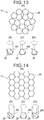
- the decorative body 14 may be structured by reflecting pieces 26 that are shaped as pentagonal pillars whose shapes as seen in plan view are pentagonal as shown in Fig. 13 , and at which the directions of the vectors of inclined surfaces 26t are different as shown in Fig. 13(B) through (D) .
- the decorative body 14 may be structured by reflecting pieces 28 that are shaped as hexagonal pillars whose shapes as seen in plan view are hexagonal as shown in Fig. 14 , and at which the directions of the vectors of inclined surfaces 28t are different as shown in Fig. 14(B) through (D) .
- Various shapes other than these can be employed as the shapes of the reflecting pieces as seen in plan view.
- the decorative body 14 may be structured by combining reflecting pieces that have different bottom surface shapes.
- a pair of the reflecting pieces 22 at which the initial point of the vector (the arrow) of one of the reflecting pieces 22 that are adjacent to one another and the initial point of the vector of the another reflecting piece 22 are adjacent to one another, and the vector of the one reflecting piece 22 and the vector of the another reflecting piece 22 face in directions opposite one another is defined as a first solid shape pair 30, as shown in Fig.
- a pair of the reflecting pieces 22 at which the terminal point of the vector of one of the reflecting pieces 16 that are adjacent to one another and the terminal point of the vector of the another reflecting piece 22 are adjacent to one another, and the vector of the one reflecting piece 22 and the vector of the another reflecting piece 22 face in directions opposite one another is defined as a second solid shape pair 32, as shown in Fig. 15(C) and 15(D) , an aggregate of the reflecting pieces 22, at which three or more of the reflecting pieces 22 at which the orientations of the vectors face in the same direction are continuous, is defined as a first solid shape group 34, and as shown in Fig.
- a pair formed from two of the reflecting pieces 22 that do not belong to any of the first solid shape pair 30, the second solid shape pair 32 and the first solid shape group 34 is defined as a third solid shape pair 36, it suffices for the decorative body 14 to, when the tire side portion 12 is seen in plan view, satisfy all conditions that are a first condition that satisfies total surface area of the third solid shape pair 36 > total surface area of the first solid shape pair 30, a second condition that satisfies total surface area of the third solid shape pair 36 > total surface area of the second solid shape pair 32, and a third condition that satisfies total surface area of the third solid shape pair 36 > total surface area of the first solid shape group 34.
- the decorative body 14 satisfy total surface area of the third solid shape pair 36 > total surface area of the first solid shape pair 30 + total surface area of the second solid shape pair 32 + total surface area of the first solid shape group 34.
- first solid shape pair 30, the second solid shape pair 32 and the first solid shape group 34 are structures by which it is difficult to obtain a sparkling sensation, they do not have to be included in the decorative body 14.
- the above-described third solid shape pair 30 corresponds to the first set 18A, the second set 18B, the third set 18C and the fourth set 18D at the decorative body 14 of the above-described embodiment. Structures corresponding to the above-described first solid shape pair 30, second solid shape pair 32 and first solid shape group 34 are not provided at the decorative body 14 of the above-described embodiment.
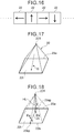
- the decorative body 14 it is preferable to exclude a structure in which, as shown in Fig. 16 as an example, when looking at three of the reflecting pieces 22 that are disposed in continuation from one side to another side when the tire side portion 12 is seen in plan view, the orientations of the rotating directions of the vectors, having a reference that is a normal line that is normal to the surface of the tire side portion 12, change by the same angle (in Fig. 16 , 90° as an example) in the same rotating direction from the one side to the other side.
- the proportion of the surface area, which is occupied by the inclined surfaces that have the smallest angles of inclination, per unit surface area of the decorative body 14 be in the range of 70 to 100%.
- the sparkling sensation can be emphasized thereby.
- 3 to 200 of the reflecting pieces 16 to be provided per 1 cm 2 , and providing 10 to 100 is more preferable.
- the sparkling sensation can be emphasized thereby.
- the surface that reflects light with respect to the observer is the inclined surface, having the angle of inclination with respect to the bottom surface of the reflecting piece which is the smallest, of the reflecting piece that is an example of the solid shape. As shown in Fig.
- highest portion (vertex) 22T of the reflecting piece 22 when considering the reflecting piece 22 whose bottom surface is quadrangular, highest portion (vertex) 22T of the reflecting piece 22 being positioned above a region that is further toward an outer peripheral side of the bottom surface of the reflecting piece 22 than center of gravity G of the bottom surface of the reflecting piece 22 that is seen in plan view, is a condition that is preferable in terms of making large the surface area of the inclined surfaces that reflect light. Note that, although not illustrated, in a case in which the highest portion is a side, the length direction central portion of that side is the vertex 22T. At the reflecting piece 22 shown in Fig.
- the highest portion 22T is positioned at a portion that is near a side 23a of the bottom surface, and, due thereto, of the plural surfaces of the reflecting piece 22 other than the bottom surface, a surface that has the greatest surface area can be formed (the inclined surface having the angle of inclination with respect to the bottom surface which is the smallest).
- ⁇ b be greater than or equal to 85° and less than or equal to 95°. Due thereto, the surface area of the inclined surface 22t, having the angle of
- the direction, which heads from the highest region side toward the lowest region side of the inclined surface having the angle of inclination with respect to the bottom surface of the reflecting piece which is the smallest, is defined as the vector of the inclined surface.
- the direction heading from the vertex 16T to center point 16cc of the side 16c is the vector (shown by the arrow).
- the reflecting piece 16 that is shaped as a triangular pillar, in a case in which any side 16c of the triangle is the highest (the height thereof is uniform), and vertex 16p of the triangle that faces this side 16c is the lowest, the direction heading from the central point of the side 16c toward the vertex 16p is the vector (shown by the arrow).
- the direction heading from the central point of the side 22a toward the central point of the side 22b is the vector (shown by the arrow).
- the direction heading from the one corner portion 22p toward the another corner portion 22d is the vector (shown by the arrow).
- the central point of that side is the initial point of the vector, and, if there is a side whose height is the lowest and that is a uniform height, the central point of that side is the terminal point of the vector.
- the inclined surface is circular, oval or the like, the highest point of the outer peripheral portion of the inclined surface is the initial point of the vector, and the lowest point is the terminal point of the vector.
- Fig. 25 shows results of evaluating (sensorially evaluating), at five levels of A, B, C, D, E, the degree of the sparkling sensation of the decorative body in a case in which the proportion that the total surface area of the inclined surfaces having angles of inclination which are the smallest occupies of a unit surface area of the decorative body when the decorative body is seen in plan view, and the density of the reflecting pieces disposed at the decorative body 14, were changed in various ways.
- a body formed from reflecting pieces that are triangular as seen in plan view was used as the decorative body that was used in testing.
- the sparkling sensation changes by combinations of the proportion of the surface area of the inclined surfaces of the reflecting pieces (structure 1) and the density of the reflecting pieces (structure 2). Namely, from the test results, it is understood that it is preferable to ensure the reflecting surface area by making the surface area of the inclined surfaces of the respective reflecting pieces large, when the decorative body 14 is viewed in plan view from the axial direction of the tire 10. Moreover, from the test results, it is understood that the density of the reflecting pieces that are disposed at the decorative body 14 is preferably 3 to 200 per 1 cm 2 , and more preferably 10 to 100 per 1 cm 2 .
Landscapes
- Engineering & Computer Science (AREA)
- Mechanical Engineering (AREA)
- Tires In General (AREA)
Applications Claiming Priority (2)
| Application Number | Priority Date | Filing Date | Title |
|---|---|---|---|
| JP2017238077A JP6940389B2 (ja) | 2017-12-12 | 2017-12-12 | 装飾体 |
| PCT/JP2018/044421 WO2019116950A1 (fr) | 2017-12-12 | 2018-12-03 | Corps décoratif |
Publications (3)
| Publication Number | Publication Date |
|---|---|
| EP3725558A1 true EP3725558A1 (fr) | 2020-10-21 |
| EP3725558A4 EP3725558A4 (fr) | 2021-09-01 |
| EP3725558B1 EP3725558B1 (fr) | 2024-02-07 |
Family
ID=66820364
Family Applications (1)
| Application Number | Title | Priority Date | Filing Date |
|---|---|---|---|
| EP18887850.8A Active EP3725558B1 (fr) | 2017-12-12 | 2018-12-03 | Corps décoratif |
Country Status (5)
| Country | Link |
|---|---|
| US (1) | US11597240B2 (fr) |
| EP (1) | EP3725558B1 (fr) |
| JP (1) | JP6940389B2 (fr) |
| CN (1) | CN111479709B (fr) |
| WO (1) | WO2019116950A1 (fr) |
Families Citing this family (6)
| Publication number | Priority date | Publication date | Assignee | Title |
|---|---|---|---|---|
| JP7445450B2 (ja) | 2020-02-10 | 2024-03-07 | Toyo Tire株式会社 | タイヤ |
| JP7415690B2 (ja) * | 2020-03-11 | 2024-01-17 | 住友ゴム工業株式会社 | タイヤ |
| KR102530621B1 (ko) * | 2021-01-14 | 2023-05-08 | 한국타이어앤테크놀로지 주식회사 | 타이어 |
| KR102651111B1 (ko) * | 2021-12-23 | 2024-03-25 | 한국타이어앤테크놀로지 주식회사 | 공력 개선용 패턴형성영역을 포함하는 타이어 |
| JP7783071B2 (ja) * | 2022-02-03 | 2025-12-09 | Toyo Tire株式会社 | 空気入りタイヤ |
| TWI819741B (zh) * | 2022-08-09 | 2023-10-21 | 正新橡膠工業股份有限公司 | 提高胎邊對比性能之結構及其輪胎 |
Family Cites Families (22)
| Publication number | Priority date | Publication date | Assignee | Title |
|---|---|---|---|---|
| JP3436401B2 (ja) * | 1993-12-10 | 2003-08-11 | 株式会社ブリヂストン | 帯状デザインを有する空気入りタイヤ |
| US6253815B1 (en) * | 1998-08-14 | 2001-07-03 | Michelin Recherche Et Techniques S.A. | Design pattern for a tire |
| JP4315515B2 (ja) * | 1999-03-30 | 2009-08-19 | 株式会社ブリヂストン | 空気入りタイヤ |
| JP4502437B2 (ja) | 2000-01-07 | 2010-07-14 | 株式会社ブリヂストン | 空気入りタイヤ |
| JP2002052294A (ja) | 2000-08-07 | 2002-02-19 | Shuichi Kitamura | ハンガー |
| JP3903372B2 (ja) * | 2001-12-10 | 2007-04-11 | 横浜ゴム株式会社 | 空気入りタイヤ |
| US7497240B2 (en) * | 2001-12-19 | 2009-03-03 | The Goodyear Tire & Rubber Company | Tire including projections having sides of unequal length and an undercut extending beneath the apex |
| JP2007091155A (ja) * | 2005-09-30 | 2007-04-12 | Yokohama Rubber Co Ltd:The | タイヤおよびタイヤ成形用金型 |
| FR2892336B1 (fr) | 2005-10-21 | 2009-10-09 | Michelin Soc Tech | Marquage offrant une meilleure visibilite et procede de marquage. |
| JP2008189165A (ja) | 2007-02-05 | 2008-08-21 | Yokohama Rubber Co Ltd:The | 空気入りタイヤ |
| US20080283169A1 (en) | 2007-02-22 | 2008-11-20 | Toyo Tire & Rubber Co., Ltd. | Pneumatic Tire |
| JP5230229B2 (ja) | 2007-04-05 | 2013-07-10 | 東洋ゴム工業株式会社 | 空気入りタイヤ |
| CN201092238Y (zh) * | 2007-09-21 | 2008-07-30 | 郑军 | 轮胎胎边立体装饰 |
| WO2012032741A1 (fr) * | 2010-09-09 | 2012-03-15 | 株式会社ブリヂストン | Pneu |
| JP2012101754A (ja) | 2010-11-12 | 2012-05-31 | Yokohama Rubber Co Ltd:The | 空気入りタイヤ及びその加硫用金型 |
| JP4947225B1 (ja) * | 2011-06-28 | 2012-06-06 | 横浜ゴム株式会社 | 空気入りタイヤ |
| JP5310805B2 (ja) | 2011-08-03 | 2013-10-09 | 横浜ゴム株式会社 | 空気入りタイヤ |
| JP5287961B2 (ja) * | 2011-09-27 | 2013-09-11 | 横浜ゴム株式会社 | 空気入りタイヤ |
| JP5785530B2 (ja) * | 2012-09-21 | 2015-09-30 | 住友ゴム工業株式会社 | 空気入りタイヤ |
| JP5789274B2 (ja) * | 2013-01-16 | 2015-10-07 | 住友ゴム工業株式会社 | 空気入りタイヤ |
| JP2017081304A (ja) * | 2015-10-26 | 2017-05-18 | 横浜ゴム株式会社 | 空気入りタイヤ |
| JP2017081305A (ja) * | 2015-10-26 | 2017-05-18 | 横浜ゴム株式会社 | 空気入りタイヤ |
-
2017
- 2017-12-12 JP JP2017238077A patent/JP6940389B2/ja active Active
-
2018
- 2018-12-03 CN CN201880080530.8A patent/CN111479709B/zh active Active
- 2018-12-03 WO PCT/JP2018/044421 patent/WO2019116950A1/fr not_active Ceased
- 2018-12-03 US US16/772,007 patent/US11597240B2/en active Active
- 2018-12-03 EP EP18887850.8A patent/EP3725558B1/fr active Active
Also Published As
| Publication number | Publication date |
|---|---|
| JP6940389B2 (ja) | 2021-09-29 |
| US11597240B2 (en) | 2023-03-07 |
| WO2019116950A1 (fr) | 2019-06-20 |
| JP2019104384A (ja) | 2019-06-27 |
| US20210086565A1 (en) | 2021-03-25 |
| EP3725558B1 (fr) | 2024-02-07 |
| CN111479709B (zh) | 2022-03-18 |
| CN111479709A (zh) | 2020-07-31 |
| EP3725558A4 (fr) | 2021-09-01 |
Similar Documents
| Publication | Publication Date | Title |
|---|---|---|
| EP3725558A1 (fr) | Corps décoratif | |
| US9365080B2 (en) | Tire | |
| EP3412477B1 (fr) | Pneumatique | |
| US20170246917A1 (en) | Pneumatic tire | |
| JP6411949B2 (ja) | タイヤ | |
| JP2011126335A (ja) | タイヤ | |
| EP3725561B1 (fr) | Corps décoratif | |
| JP6495734B2 (ja) | タイヤ | |
| JP6495736B2 (ja) | タイヤ | |
| US20200276869A1 (en) | Tire | |
| US20260061781A1 (en) | High contrast patterns for sidewall or tread | |
| CN111491810B (zh) | 装饰体 | |
| JP6549414B2 (ja) | タイヤ | |
| JP6436860B2 (ja) | タイヤ | |
| US20240123770A1 (en) | Tire | |
| US11479061B2 (en) | Tire | |
| US20200369092A1 (en) | Tire | |
| JP2016215701A (ja) | タイヤ |
Legal Events
| Date | Code | Title | Description |
|---|---|---|---|
| STAA | Information on the status of an ep patent application or granted ep patent |
Free format text: STATUS: THE INTERNATIONAL PUBLICATION HAS BEEN MADE |
|
| PUAI | Public reference made under article 153(3) epc to a published international application that has entered the european phase |
Free format text: ORIGINAL CODE: 0009012 |
|
| STAA | Information on the status of an ep patent application or granted ep patent |
Free format text: STATUS: REQUEST FOR EXAMINATION WAS MADE |
|
| 17P | Request for examination filed |
Effective date: 20200623 |
|
| AK | Designated contracting states |
Kind code of ref document: A1 Designated state(s): AL AT BE BG CH CY CZ DE DK EE ES FI FR GB GR HR HU IE IS IT LI LT LU LV MC MK MT NL NO PL PT RO RS SE SI SK SM TR |
|
| AX | Request for extension of the european patent |
Extension state: BA ME |
|
| DAV | Request for validation of the european patent (deleted) | ||
| DAX | Request for extension of the european patent (deleted) | ||
| A4 | Supplementary search report drawn up and despatched |
Effective date: 20210729 |
|
| RIC1 | Information provided on ipc code assigned before grant |
Ipc: B60C 13/00 20060101AFI20210723BHEP |
|
| STAA | Information on the status of an ep patent application or granted ep patent |
Free format text: STATUS: EXAMINATION IS IN PROGRESS |
|
| 17Q | First examination report despatched |
Effective date: 20221129 |
|
| GRAP | Despatch of communication of intention to grant a patent |
Free format text: ORIGINAL CODE: EPIDOSNIGR1 |
|
| STAA | Information on the status of an ep patent application or granted ep patent |
Free format text: STATUS: GRANT OF PATENT IS INTENDED |
|
| INTG | Intention to grant announced |
Effective date: 20230711 |
|
| P01 | Opt-out of the competence of the unified patent court (upc) registered |
Effective date: 20230810 |
|
| GRAS | Grant fee paid |
Free format text: ORIGINAL CODE: EPIDOSNIGR3 |
|
| GRAA | (expected) grant |
Free format text: ORIGINAL CODE: 0009210 |
|
| STAA | Information on the status of an ep patent application or granted ep patent |
Free format text: STATUS: THE PATENT HAS BEEN GRANTED |
|
| AK | Designated contracting states |
Kind code of ref document: B1 Designated state(s): AL AT BE BG CH CY CZ DE DK EE ES FI FR GB GR HR HU IE IS IT LI LT LU LV MC MK MT NL NO PL PT RO RS SE SI SK SM TR |
|
| REG | Reference to a national code |
Ref country code: GB Ref legal event code: FG4D |
|
| REG | Reference to a national code |
Ref country code: CH Ref legal event code: EP |
|
| REG | Reference to a national code |
Ref country code: DE Ref legal event code: R096 Ref document number: 602018065051 Country of ref document: DE |
|
| REG | Reference to a national code |
Ref country code: IE Ref legal event code: FG4D |
|
| REG | Reference to a national code |
Ref country code: LT Ref legal event code: MG9D |
|
| REG | Reference to a national code |
Ref country code: NL Ref legal event code: MP Effective date: 20240207 |
|
| PG25 | Lapsed in a contracting state [announced via postgrant information from national office to epo] |
Ref country code: IS Free format text: LAPSE BECAUSE OF FAILURE TO SUBMIT A TRANSLATION OF THE DESCRIPTION OR TO PAY THE FEE WITHIN THE PRESCRIBED TIME-LIMIT Effective date: 20240607 |
|
| PG25 | Lapsed in a contracting state [announced via postgrant information from national office to epo] |
Ref country code: LT Free format text: LAPSE BECAUSE OF FAILURE TO SUBMIT A TRANSLATION OF THE DESCRIPTION OR TO PAY THE FEE WITHIN THE PRESCRIBED TIME-LIMIT Effective date: 20240207 |
|
| PG25 | Lapsed in a contracting state [announced via postgrant information from national office to epo] |
Ref country code: GR Free format text: LAPSE BECAUSE OF FAILURE TO SUBMIT A TRANSLATION OF THE DESCRIPTION OR TO PAY THE FEE WITHIN THE PRESCRIBED TIME-LIMIT Effective date: 20240508 |
|
| REG | Reference to a national code |
Ref country code: AT Ref legal event code: MK05 Ref document number: 1655155 Country of ref document: AT Kind code of ref document: T Effective date: 20240207 |
|
| PG25 | Lapsed in a contracting state [announced via postgrant information from national office to epo] |
Ref country code: HR Free format text: LAPSE BECAUSE OF FAILURE TO SUBMIT A TRANSLATION OF THE DESCRIPTION OR TO PAY THE FEE WITHIN THE PRESCRIBED TIME-LIMIT Effective date: 20240207 Ref country code: NL Free format text: LAPSE BECAUSE OF FAILURE TO SUBMIT A TRANSLATION OF THE DESCRIPTION OR TO PAY THE FEE WITHIN THE PRESCRIBED TIME-LIMIT Effective date: 20240207 Ref country code: RS Free format text: LAPSE BECAUSE OF FAILURE TO SUBMIT A TRANSLATION OF THE DESCRIPTION OR TO PAY THE FEE WITHIN THE PRESCRIBED TIME-LIMIT Effective date: 20240507 |
|
| PG25 | Lapsed in a contracting state [announced via postgrant information from national office to epo] |
Ref country code: ES Free format text: LAPSE BECAUSE OF FAILURE TO SUBMIT A TRANSLATION OF THE DESCRIPTION OR TO PAY THE FEE WITHIN THE PRESCRIBED TIME-LIMIT Effective date: 20240207 |
|
| PG25 | Lapsed in a contracting state [announced via postgrant information from national office to epo] |
Ref country code: AT Free format text: LAPSE BECAUSE OF FAILURE TO SUBMIT A TRANSLATION OF THE DESCRIPTION OR TO PAY THE FEE WITHIN THE PRESCRIBED TIME-LIMIT Effective date: 20240207 |
|
| PG25 | Lapsed in a contracting state [announced via postgrant information from national office to epo] |
Ref country code: RS Free format text: LAPSE BECAUSE OF FAILURE TO SUBMIT A TRANSLATION OF THE DESCRIPTION OR TO PAY THE FEE WITHIN THE PRESCRIBED TIME-LIMIT Effective date: 20240507 Ref country code: NO Free format text: LAPSE BECAUSE OF FAILURE TO SUBMIT A TRANSLATION OF THE DESCRIPTION OR TO PAY THE FEE WITHIN THE PRESCRIBED TIME-LIMIT Effective date: 20240507 Ref country code: NL Free format text: LAPSE BECAUSE OF FAILURE TO SUBMIT A TRANSLATION OF THE DESCRIPTION OR TO PAY THE FEE WITHIN THE PRESCRIBED TIME-LIMIT Effective date: 20240207 Ref country code: LT Free format text: LAPSE BECAUSE OF FAILURE TO SUBMIT A TRANSLATION OF THE DESCRIPTION OR TO PAY THE FEE WITHIN THE PRESCRIBED TIME-LIMIT Effective date: 20240207 Ref country code: IS Free format text: LAPSE BECAUSE OF FAILURE TO SUBMIT A TRANSLATION OF THE DESCRIPTION OR TO PAY THE FEE WITHIN THE PRESCRIBED TIME-LIMIT Effective date: 20240607 Ref country code: HR Free format text: LAPSE BECAUSE OF FAILURE TO SUBMIT A TRANSLATION OF THE DESCRIPTION OR TO PAY THE FEE WITHIN THE PRESCRIBED TIME-LIMIT Effective date: 20240207 Ref country code: GR Free format text: LAPSE BECAUSE OF FAILURE TO SUBMIT A TRANSLATION OF THE DESCRIPTION OR TO PAY THE FEE WITHIN THE PRESCRIBED TIME-LIMIT Effective date: 20240508 Ref country code: FI Free format text: LAPSE BECAUSE OF FAILURE TO SUBMIT A TRANSLATION OF THE DESCRIPTION OR TO PAY THE FEE WITHIN THE PRESCRIBED TIME-LIMIT Effective date: 20240207 Ref country code: ES Free format text: LAPSE BECAUSE OF FAILURE TO SUBMIT A TRANSLATION OF THE DESCRIPTION OR TO PAY THE FEE WITHIN THE PRESCRIBED TIME-LIMIT Effective date: 20240207 Ref country code: BG Free format text: LAPSE BECAUSE OF FAILURE TO SUBMIT A TRANSLATION OF THE DESCRIPTION OR TO PAY THE FEE WITHIN THE PRESCRIBED TIME-LIMIT Effective date: 20240207 Ref country code: AT Free format text: LAPSE BECAUSE OF FAILURE TO SUBMIT A TRANSLATION OF THE DESCRIPTION OR TO PAY THE FEE WITHIN THE PRESCRIBED TIME-LIMIT Effective date: 20240207 |
|
| PG25 | Lapsed in a contracting state [announced via postgrant information from national office to epo] |
Ref country code: PL Free format text: LAPSE BECAUSE OF FAILURE TO SUBMIT A TRANSLATION OF THE DESCRIPTION OR TO PAY THE FEE WITHIN THE PRESCRIBED TIME-LIMIT Effective date: 20240207 Ref country code: PT Free format text: LAPSE BECAUSE OF FAILURE TO SUBMIT A TRANSLATION OF THE DESCRIPTION OR TO PAY THE FEE WITHIN THE PRESCRIBED TIME-LIMIT Effective date: 20240607 |
|
| PG25 | Lapsed in a contracting state [announced via postgrant information from national office to epo] |
Ref country code: SE Free format text: LAPSE BECAUSE OF FAILURE TO SUBMIT A TRANSLATION OF THE DESCRIPTION OR TO PAY THE FEE WITHIN THE PRESCRIBED TIME-LIMIT Effective date: 20240207 Ref country code: PT Free format text: LAPSE BECAUSE OF FAILURE TO SUBMIT A TRANSLATION OF THE DESCRIPTION OR TO PAY THE FEE WITHIN THE PRESCRIBED TIME-LIMIT Effective date: 20240607 Ref country code: PL Free format text: LAPSE BECAUSE OF FAILURE TO SUBMIT A TRANSLATION OF THE DESCRIPTION OR TO PAY THE FEE WITHIN THE PRESCRIBED TIME-LIMIT Effective date: 20240207 Ref country code: LV Free format text: LAPSE BECAUSE OF FAILURE TO SUBMIT A TRANSLATION OF THE DESCRIPTION OR TO PAY THE FEE WITHIN THE PRESCRIBED TIME-LIMIT Effective date: 20240207 |
|
| PG25 | Lapsed in a contracting state [announced via postgrant information from national office to epo] |
Ref country code: DK Free format text: LAPSE BECAUSE OF FAILURE TO SUBMIT A TRANSLATION OF THE DESCRIPTION OR TO PAY THE FEE WITHIN THE PRESCRIBED TIME-LIMIT Effective date: 20240207 |
|
| PG25 | Lapsed in a contracting state [announced via postgrant information from national office to epo] |
Ref country code: SM Free format text: LAPSE BECAUSE OF FAILURE TO SUBMIT A TRANSLATION OF THE DESCRIPTION OR TO PAY THE FEE WITHIN THE PRESCRIBED TIME-LIMIT Effective date: 20240207 |
|
| PG25 | Lapsed in a contracting state [announced via postgrant information from national office to epo] |
Ref country code: CZ Free format text: LAPSE BECAUSE OF FAILURE TO SUBMIT A TRANSLATION OF THE DESCRIPTION OR TO PAY THE FEE WITHIN THE PRESCRIBED TIME-LIMIT Effective date: 20240207 Ref country code: EE Free format text: LAPSE BECAUSE OF FAILURE TO SUBMIT A TRANSLATION OF THE DESCRIPTION OR TO PAY THE FEE WITHIN THE PRESCRIBED TIME-LIMIT Effective date: 20240207 |
|
| PG25 | Lapsed in a contracting state [announced via postgrant information from national office to epo] |
Ref country code: SK Free format text: LAPSE BECAUSE OF FAILURE TO SUBMIT A TRANSLATION OF THE DESCRIPTION OR TO PAY THE FEE WITHIN THE PRESCRIBED TIME-LIMIT Effective date: 20240207 |
|
| PG25 | Lapsed in a contracting state [announced via postgrant information from national office to epo] |
Ref country code: SM Free format text: LAPSE BECAUSE OF FAILURE TO SUBMIT A TRANSLATION OF THE DESCRIPTION OR TO PAY THE FEE WITHIN THE PRESCRIBED TIME-LIMIT Effective date: 20240207 Ref country code: SK Free format text: LAPSE BECAUSE OF FAILURE TO SUBMIT A TRANSLATION OF THE DESCRIPTION OR TO PAY THE FEE WITHIN THE PRESCRIBED TIME-LIMIT Effective date: 20240207 Ref country code: RO Free format text: LAPSE BECAUSE OF FAILURE TO SUBMIT A TRANSLATION OF THE DESCRIPTION OR TO PAY THE FEE WITHIN THE PRESCRIBED TIME-LIMIT Effective date: 20240207 Ref country code: EE Free format text: LAPSE BECAUSE OF FAILURE TO SUBMIT A TRANSLATION OF THE DESCRIPTION OR TO PAY THE FEE WITHIN THE PRESCRIBED TIME-LIMIT Effective date: 20240207 Ref country code: DK Free format text: LAPSE BECAUSE OF FAILURE TO SUBMIT A TRANSLATION OF THE DESCRIPTION OR TO PAY THE FEE WITHIN THE PRESCRIBED TIME-LIMIT Effective date: 20240207 Ref country code: CZ Free format text: LAPSE BECAUSE OF FAILURE TO SUBMIT A TRANSLATION OF THE DESCRIPTION OR TO PAY THE FEE WITHIN THE PRESCRIBED TIME-LIMIT Effective date: 20240207 |
|
| REG | Reference to a national code |
Ref country code: DE Ref legal event code: R097 Ref document number: 602018065051 Country of ref document: DE |
|
| PG25 | Lapsed in a contracting state [announced via postgrant information from national office to epo] |
Ref country code: IT Free format text: LAPSE BECAUSE OF FAILURE TO SUBMIT A TRANSLATION OF THE DESCRIPTION OR TO PAY THE FEE WITHIN THE PRESCRIBED TIME-LIMIT Effective date: 20240207 |
|
| PLBE | No opposition filed within time limit |
Free format text: ORIGINAL CODE: 0009261 |
|
| STAA | Information on the status of an ep patent application or granted ep patent |
Free format text: STATUS: NO OPPOSITION FILED WITHIN TIME LIMIT |
|
| PG25 | Lapsed in a contracting state [announced via postgrant information from national office to epo] |
Ref country code: IT Free format text: LAPSE BECAUSE OF FAILURE TO SUBMIT A TRANSLATION OF THE DESCRIPTION OR TO PAY THE FEE WITHIN THE PRESCRIBED TIME-LIMIT Effective date: 20240207 |
|
| 26N | No opposition filed |
Effective date: 20241108 |
|
| PG25 | Lapsed in a contracting state [announced via postgrant information from national office to epo] |
Ref country code: SI Free format text: LAPSE BECAUSE OF FAILURE TO SUBMIT A TRANSLATION OF THE DESCRIPTION OR TO PAY THE FEE WITHIN THE PRESCRIBED TIME-LIMIT Effective date: 20240207 |
|
| PG25 | Lapsed in a contracting state [announced via postgrant information from national office to epo] |
Ref country code: MC Free format text: LAPSE BECAUSE OF FAILURE TO SUBMIT A TRANSLATION OF THE DESCRIPTION OR TO PAY THE FEE WITHIN THE PRESCRIBED TIME-LIMIT Effective date: 20240207 |
|
| REG | Reference to a national code |
Ref country code: CH Ref legal event code: PL |
|
| PG25 | Lapsed in a contracting state [announced via postgrant information from national office to epo] |
Ref country code: LU Free format text: LAPSE BECAUSE OF NON-PAYMENT OF DUE FEES Effective date: 20241203 |
|
| GBPC | Gb: european patent ceased through non-payment of renewal fee |
Effective date: 20241203 |
|
| REG | Reference to a national code |
Ref country code: BE Ref legal event code: MM Effective date: 20241231 |
|
| PG25 | Lapsed in a contracting state [announced via postgrant information from national office to epo] |
Ref country code: GB Free format text: LAPSE BECAUSE OF NON-PAYMENT OF DUE FEES Effective date: 20241203 Ref country code: BE Free format text: LAPSE BECAUSE OF NON-PAYMENT OF DUE FEES Effective date: 20241231 |
|
| PG25 | Lapsed in a contracting state [announced via postgrant information from national office to epo] |
Ref country code: CH Free format text: LAPSE BECAUSE OF NON-PAYMENT OF DUE FEES Effective date: 20241231 |
|
| PG25 | Lapsed in a contracting state [announced via postgrant information from national office to epo] |
Ref country code: IE Free format text: LAPSE BECAUSE OF NON-PAYMENT OF DUE FEES Effective date: 20241203 |
|
| PGFP | Annual fee paid to national office [announced via postgrant information from national office to epo] |
Ref country code: DE Payment date: 20251211 Year of fee payment: 8 |
|
| PGFP | Annual fee paid to national office [announced via postgrant information from national office to epo] |
Ref country code: FR Payment date: 20251229 Year of fee payment: 8 |
|
| PG25 | Lapsed in a contracting state [announced via postgrant information from national office to epo] |
Ref country code: CY Free format text: LAPSE BECAUSE OF FAILURE TO SUBMIT A TRANSLATION OF THE DESCRIPTION OR TO PAY THE FEE WITHIN THE PRESCRIBED TIME-LIMIT; INVALID AB INITIO Effective date: 20181203 |