EP3726110B1 - Ventileinrichtung für eine pneumatisch betätigbare reibungskupplung - Google Patents
Ventileinrichtung für eine pneumatisch betätigbare reibungskupplung Download PDFInfo
- Publication number
- EP3726110B1 EP3726110B1 EP20167454.6A EP20167454A EP3726110B1 EP 3726110 B1 EP3726110 B1 EP 3726110B1 EP 20167454 A EP20167454 A EP 20167454A EP 3726110 B1 EP3726110 B1 EP 3726110B1
- Authority
- EP
- European Patent Office
- Prior art keywords
- valve
- housing
- inlet
- outlet
- pressure
- Prior art date
- Legal status (The legal status is an assumption and is not a legal conclusion. Google has not performed a legal analysis and makes no representation as to the accuracy of the status listed.)
- Active
Links
Images


Classifications
-
- F—MECHANICAL ENGINEERING; LIGHTING; HEATING; WEAPONS; BLASTING
- F16—ENGINEERING ELEMENTS AND UNITS; GENERAL MEASURES FOR PRODUCING AND MAINTAINING EFFECTIVE FUNCTIONING OF MACHINES OR INSTALLATIONS; THERMAL INSULATION IN GENERAL
- F16K—VALVES; TAPS; COCKS; ACTUATING-FLOATS; DEVICES FOR VENTING OR AERATING
- F16K15/00—Check valves
- F16K15/18—Check valves with actuating mechanism; Combined check valves and actuated valves
-
- F—MECHANICAL ENGINEERING; LIGHTING; HEATING; WEAPONS; BLASTING
- F16—ENGINEERING ELEMENTS AND UNITS; GENERAL MEASURES FOR PRODUCING AND MAINTAINING EFFECTIVE FUNCTIONING OF MACHINES OR INSTALLATIONS; THERMAL INSULATION IN GENERAL
- F16K—VALVES; TAPS; COCKS; ACTUATING-FLOATS; DEVICES FOR VENTING OR AERATING
- F16K11/00—Multiple-way valves, e.g. mixing valves; Pipe fittings incorporating such valves
- F16K11/10—Multiple-way valves, e.g. mixing valves; Pipe fittings incorporating such valves with two or more closure members not moving as a unit
-
- F—MECHANICAL ENGINEERING; LIGHTING; HEATING; WEAPONS; BLASTING
- F16—ENGINEERING ELEMENTS AND UNITS; GENERAL MEASURES FOR PRODUCING AND MAINTAINING EFFECTIVE FUNCTIONING OF MACHINES OR INSTALLATIONS; THERMAL INSULATION IN GENERAL
- F16K—VALVES; TAPS; COCKS; ACTUATING-FLOATS; DEVICES FOR VENTING OR AERATING
- F16K7/00—Diaphragm valves or cut-off apparatus, e.g. with a member deformed, but not moved bodily, to close the passage ; Pinch valves
- F16K7/02—Diaphragm valves or cut-off apparatus, e.g. with a member deformed, but not moved bodily, to close the passage ; Pinch valves with tubular diaphragm
- F16K7/04—Diaphragm valves or cut-off apparatus, e.g. with a member deformed, but not moved bodily, to close the passage ; Pinch valves with tubular diaphragm constrictable by external radial force
- F16K7/07—Diaphragm valves or cut-off apparatus, e.g. with a member deformed, but not moved bodily, to close the passage ; Pinch valves with tubular diaphragm constrictable by external radial force by means of fluid pressure
Definitions
- the invention relates to a valve device for a pneumatically actuated friction clutch, comprising an inlet valve designed as a 2/2-way solenoid seat valve, which can be connected on the inlet side to a pressurized supply line and on the outlet side to a working inlet of an actuating cylinder of the friction clutch, and an outlet valve designed as a 2/2-way solenoid seat valve, which can be connected on the inlet side to the working inlet of the actuating cylinder and on the outlet side to a venting outlet.
- an inlet valve designed as a 2/2-way solenoid seat valve which can be connected on the inlet side to a pressurized supply line and on the outlet side to a working inlet of an actuating cylinder of the friction clutch
- an outlet valve designed as a 2/2-way solenoid seat valve which can be connected on the inlet side to the working inlet of the actuating cylinder and on the outlet side to a venting outlet.
- opening the inlet valve pressurizes the associated actuating cylinder, thereby disengaging or engaging the friction clutch depending on the design. Opening the outlet valve vents the actuating cylinder, thereby engaging or disengaging the friction clutch depending on the design.
- the pressure-maintaining valve which is a check valve closing towards the inlet valve, has the function of maintaining the working pressure in the actuating cylinder when the inlet valve is open and the actuating cylinder is pressurized, provided the supply pressure in the supply line drops, for example due to a line break or a defect in the compressed air supply system. This prevents unintentional actuation of the friction clutch caused by uncontrolled venting of the actuating cylinder.
- the drain valve which is a check valve that closes towards a vent outlet when the air pressure on the inlet side is high and opens when the air pressure on the inlet side is low, has the function of draining compressed air flowing in via the inlet valve due to leakage when the inlet valve is closed and the actuating cylinder is vented, thus preventing unintentional actuation of the friction clutch caused by uncontrolled ventilation of the actuating cylinder.
- Such a valve device of a pneumatically actuated friction clutch is known, for example, from DE 102 10 877 A1
- the drain valve is designed as a ball check valve or as a piston check valve and is located either in the piston of the actuating cylinder, in the housing of the actuating cylinder or in the housing of the outlet valve Due to their design, the discharge valve versions used there have a large axial height relative to the opening cross-section, which makes their integration into the housing of another valve, such as an inlet valve or an outlet valve, difficult. Furthermore, the valve device described there does not have a pressure-maintaining valve.
- DE102007002899A1 discloses a valve arrangement for a motor vehicle comprising an inlet chamber connected to an inlet and an outlet chamber separated from the inlet chamber by a partition wall and connected to an outlet, and a check valve integrated into the partition wall which releases a passage from the inlet chamber to the outlet chamber as of a minimum overpressure, and a pressure control valve integrated into the partition wall which blocks a passage from the outlet chamber to the inlet chamber as of a minimum underpressure.
- US4729401A discloses a valve assembly.
- the valve assembly comprises a main body having two passages therein which meet at a large central cavity within the body; a body cap for closing an open side of the central cavity in the main body, the cap having an outlet passage; a central support structure within the central cavity of the main body; two coaxial valve discs mounted within the central body cavity and held in operative relationship by the central support structure; and wherein the main body, the body cap, and the central support structure each have valve disc support means.
- WO2012131503A1 refers to irrigation valves and in particular to irrigation valves that can be controlled by an external signal.
- valves of such valve systems have been designed separately and connected mechanically and fluidically via screw connections or plug-in connections. This inevitably results in larger dimensions for the valve system and requires relatively high assembly effort.
- the present invention was therefore based on the object of presenting a valve device for a pneumatically actuated friction clutch of the type mentioned at the outset, which has comparatively compact dimensions and requires little assembly effort.
- the invention therefore relates to a valve device for a pneumatically actuated friction clutch, comprising an inlet valve designed as a 2/2-way solenoid seat valve, which can be connected on the inlet side to a pressurized supply line and on the outlet side to a working inlet of an actuating cylinder of the friction clutch, an outlet valve designed as a 2/2-way solenoid seat valve, which can be connected on the inlet side to the working inlet of the actuating cylinder and on the outlet side to a vent outlet, a pressure holding valve designed as a check valve, which can be connected on the inlet side to the outlet of the inlet valve and on the outlet side to the working inlet of the actuating cylinder, and a drain valve designed as a check valve, which can be connected on the inlet side to the working inlet of the actuating cylinder and on the outlet side to a vent outlet.
- this valve device further provides that the pressure-maintaining valve is arranged within the valve housing of the inlet valve coaxially to its valve seat between a central channel adjacent to the valve seat and an outlet chamber connected to the outlet of the inlet valve, and that the discharge valve is arranged within the valve housing of the inlet valve, or that the discharge valve is arranged within the valve housing of the outlet valve.
- the pressure-maintaining valve and the discharge valve of the valve device are designed as diaphragm disc valves.
- the pressure holding valve and the drain valve Due to this design of the pressure holding valve and the drain valve, these valves have a comparatively low axial height in relation to their opening cross-section and can therefore be easily integrated into the housing of the inlet valve and/or the outlet valve.
- the pressure holding valve and the drain valve By integrating the pressure holding valve and the drain valve into the inlet valve (first embodiment) or the pressure holding valve into the inlet valve and the drain valve into the outlet valve (second embodiment), installation space is saved and assembly effort is significantly reduced, since the number of valve units to be assembled in both embodiments is reduced from four to two.
- the drain valve is arranged within the valve housing of the inlet valve coaxially to its valve seat and axially adjacent to the pressure holding valve in an opening in a housing wall of the valve housing adjacent to the outlet chamber. This results in a particularly space-saving design.
- the drain valve is arranged within the valve housing of the outlet valve coaxially with its valve seat in an opening in a housing wall of the valve housing adjacent to an inlet chamber connected to the inlet of the outlet valve. This also creates a very compact valve design.
- a flexurally elastic membrane disc is arranged at least partially within an annular-cylindrical housing axially between a conical support body connected to the housing via at least one diagonal strut and an annular collar of the housing or an axially adjacent component.
- the diaphragm disc of the pressure holding valve and/or the drain valve can each be mounted exclusively in a floating manner within the respective housing, i.e. can be arranged without any special fastening.
- the respective diaphragm disc of the pressure holding valve and/or the discharge valve can be fastened by slipping the central bore of the diaphragm disc over a mushroom head of the respective housing which is fastened to the tip of the respective support body or is integrally formed on the support body.
- the housing of the pressure-maintaining valve is preferably inserted precisely into the housing of the discharge valve and is fastened via this to a housing insert of the inlet valve having the valve seat.
- the housing of the pressure-maintaining valve is preferably directly locked to the housing insert of the inlet valve having the valve seat.
- the housing of the discharge valve is locked to a housing insert of the inlet valve or the outlet valve having the valve seat, depending on the design variant of the valve device according to the invention.
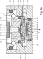
- the valve device 2, 2' of a pneumatically actuated friction clutch shown schematically comprises an inlet valve 4, 4', an outlet valve 6, 6', a pressure holding valve 8, 8' and a drain valve 10, 10'.
- the inlet valve 4, 4' is designed as a 2/2-way solenoid seat valve and has an inlet 12 and a Outlet 14.
- a pressurized supply line 18, which is connected to a compressed air source 16, is connected to the inlet 12 of the inlet valve 4, 4'.
- a working inlet 24 of an actuating cylinder 20 of the friction clutch is connected to the outlet 14 of the inlet valve 4, 4'.
- the actuating cylinder 20 is designed as a piston-cylinder arrangement.
- the inlet valve 4, 4' In the de-energized state shown, the inlet valve 4, 4' is closed, i.e., the inlet 12 is blocked off from the outlet 14. This vents the pressure chamber 22 of the actuating cylinder 20 and, depending on the design, the friction clutch is engaged or disengaged. In the energized state, the inlet valve 4, 4' is open, i.e., the outlet 14 is connected to the inlet 12, whereby the pressure chamber 22 of the actuating cylinder 20 is vented and, depending on the design, the friction clutch is disengaged or disengaged.
- the outlet valve 6, 6' is also designed as a 2/2-way solenoid seat valve and has an inlet 26 and an outlet 28.
- the working inlet 24 of the actuating cylinder 20 is connected to the inlet 26 of the outlet valve 6, 6'.
- a vent outlet 30 leading to the atmosphere is connected to the outlet 28 of the outlet valve 6, 6'.
- the outlet valve 6, 6' is closed, i.e., the inlet 26 is blocked off from the outlet 28.
- the pressure chamber 22 of the actuating cylinder 20 if vented, is not vented via the outlet valve 6, 6', and the friction clutch remains disengaged or engaged, depending on the design.
- the outlet valve 6, 6' is open, i.e. its inlet 26 is connected to its outlet 28, whereby the pressure chamber 22 of the actuating cylinder 20, if it is ventilated, is vented via the outlet valve 6, 6' and the friction clutch is engaged or disengaged depending on the design.
- the pressure-maintaining valve 8, 8' is arranged between the outlet 14 of the inlet valve 4, 4' and the working inlet 24 of the actuating cylinder 20 and is designed as a check valve closing in the direction of the inlet valve 4, 4'.
- the pressure-maintaining valve 8, 8' functions to maintain the working pressure in the pressure chamber 22 of the actuating cylinder 20, provided that the supply pressure present in the supply line 18 is reduced, for example, due to a line break or a defect in the compressed air source 16 (compressed air supply device). This prevents unintentional actuation of the friction clutch caused by uncontrolled venting of the actuating cylinder 20.
- the drain valve 10, 10' is located between the working inlet 24 of the actuating cylinder 20 and the inlet 26 of the outlet valve 6, 6'. It is designed as a check valve that closes towards a vent outlet 32 leading to the atmosphere when the inlet air pressure is high and opens when the inlet air pressure is low.
- the drain valve 10, 10' functions to vent compressed air flowing in through the inlet valve 4, 4' due to leakage, thus preventing unintentional actuation of the friction clutch caused by uncontrolled venting of the actuating cylinder 20.
- the inlet valve 4 is designed as a 2/2-way solenoid seat valve.
- the valve housing 34 of the inlet valve 4 has a cylindrical interior 40, which is connected to the inlet 12 of the inlet valve 4 and, via an annular cylindrical outlet chamber 42, to the outlet 14 of the inlet valve 4.
- a stepped cylindrical housing insert 44 provided with diagonal openings 46 is inserted into the interior 40.
- the housing insert has a valve seat 48 and a cylindrical central channel 50 radially adjacent to the valve seat and leading toward the outlet chamber 42.
- the inlet 12 and the interior 40 of the valve housing 34 are sealed by two sealing rings 56, 58 arranged between the inner wall of the interior 40 and the housing insert 44.
- the valve seat 48 can be closed by means of a cylindrical disk-shaped sealing element 60, which is held on the valve seat 48 by a valve spring in a manner not shown and can be lifted off the valve seat 48 by energizing an electromagnet.
- the pressure-retaining valve 8 is designed as a diaphragm disc valve.
- the pressure-retaining valve 8 is arranged coaxially with the valve seat 48 between the central channel 50 of the housing insert 44 and the outlet chamber 42.
- the pressure-retaining valve 8 has a flexurally elastic diaphragm disc 72, which is guided axially at least partially within an annular-cylindrical housing 62 between a conical support body 66 connected to the housing 62 via at least one diagonal strut 64 and an annular collar 52 around the central channel 50 of the housing insert 44.
- the drain valve 10 is designed as a diaphragm disc valve.
- the drain valve 10 is arranged coaxially with the valve seat 48 and axially adjacent to the pressure-maintaining valve 8 in an opening 38 in a housing wall 36 of the valve housing 34, said housing wall being axially adjacent to the outlet chamber 42.
- the drain valve 10 has a flexurally elastic diaphragm disc 92, which is guided in a floating manner within an annular-cylindrical housing 76 axially between an annular valve seat 78 of the housing 76 and a conical support body 82 connected to the housing 76 via at least one diagonal strut 80, as well as the aforementioned diagonal strut 64 and the support body 66 of the pressure-maintaining valve 8.
- the outlet chamber 42 of the valve housing 34 is sealed by a sealing ring 96 arranged between the inner wall of the opening 38 in the housing wall 36 and the housing 76 of the drain valve 10.
- the housing 76 of the drain valve 10 which is preferably made of a plastic and manufactured as an injection-molded component, is locked to the housing insert 44 by means of locking lugs 90, which are arranged on an axial extension 86 of the housing 76 provided with radial openings 88, by engaging in an associated internal groove 54 in the housing insert 44.
- the housing 62 of the pressure-maintaining valve 8 which is also preferably made of a plastic and manufactured as an injection-molded component, is inserted with a precise fit radially inward into the housing 76 of the drain valve 10 and is fastened to the housing insert 44 via the housing.
- the sealing element 60 rests against the valve seat 48, so that the inlet valve 4 is closed.
- the outlet chamber 42 is pressureless, so that the diaphragm disc 72 of the pressure-maintaining valve 8, due to its inherent stress, rests against the Annular collar 52 of the housing insert 44 rests, i.e. the pressure holding valve 8 is closed.
- the diaphragm disc 92 of the drain valve 10 is lifted from the valve seat 78 and has assumed a flat shape, so that the drain valve 10 is open.
- the sealing element 60 of the inlet valve 4 is lifted off the valve seat 48, so that the inlet valve 4 is open.
- the diaphragm disc 72 of the pressure-maintaining valve 8 is lifted off the annular collar 52 of the housing insert 44 and turned inside out until its radially outer edge rests against the diagonal strut 64, so that the pressure-maintaining valve 8 is now open.
- the diaphragm disc 92 of the discharge valve 10 rests on the valve seat 78, so that the discharge valve 10 is closed.
- compressed air flows from the supply line 18 connected to the inlet 12 of the inlet valve 4 via the open inlet valve 4 and the open pressure-maintaining valve 8 into the pressure chamber 22 of the actuating cylinder 20 connected to the outlet 14 of the inlet valve 4, whereby the respective friction clutch is actuated in the intended manner, i.e., disengaged or engaged depending on the design.
- a pressure drop now occurs in the supply line 18 connected to the inlet 12 of the inlet valve 4 the diaphragm disc 72 of the pressure-maintaining valve 8 is pressed against the annular collar 52 of the housing insert 4 due to the effective pressure difference, so that the pressure-maintaining valve 8 is then closed. This prevents a sudden loss of pressure in the actuating cylinder 20 connected to the outlet 14 of the inlet valve 4 and the resulting unintentional actuation of the relevant friction clutch.
- the number of valve units to be mounted in the valve device 2 is reduced from four to two valve units, thus reducing the assembly effort accordingly and also saving installation space.
- the pressure-maintaining valve 8' is arranged within the housing 34' of the inlet valve 4' and is thus integrated into the inlet valve 4' ( Fig. 2a , Fig. 2b ) and the drain valve 10' are arranged within the housing 104 of the outlet valve 6' and thus integrated into the outlet valve 6' ( Fig. 3a , Fig. 3b ).
- the inlet valve 4' according to the Figures 2a and 2b is largely identical to the inlet valve 4 according to the Figures 1a and 1b constructed and differs from this only in that now only the pressure-maintaining valve 8' is arranged within the valve housing 34' of the inlet valve 4', and that the diaphragm disc 72' of the pressure-maintaining valve 8' is now additionally fastened to the support body 66' of the housing 62'.
- the support body 66' is provided at its tip with an integrally formed mushroom head 68, onto which the diaphragm disc 72' is slipped by means of its central bore 74. The diaphragm disc 72' is thus secured against displacement from the centered desired position.
- the housing 62' of the pressure-maintaining valve 8' which is preferably made of a plastic and manufactured as an injection-molded component, is locked to the housing 62' by means of locking lugs 70 arranged on the housing 62' by engaging in the aforementioned inner groove 54 of the housing insert 44.
- the sealing element 60 is lifted from the valve seat 48 of the inlet valve 4', so that the inlet valve 4' is open.
- the diaphragm disc 72' of the pressure-maintaining valve 8' is lifted from the annular collar 52 of the housing insert 44 and turned inside out until its radially outer end rests against the diagonal strut 64', so that the pressure-maintaining valve 8' is open.
- compressed air flows from the supply line 18 connected to the inlet 12 of the inlet valve 4' via the open inlet valve 4' and the open pressure-maintaining valve 8' into the pressure chamber 22 of the actuating cylinder 20 connected to the outlet 14 of the inlet valve 4.
- This actuates the friction clutch in the intended manner, i.e., depending on the design, it is disengaged or engaged.
- the outlet valve 6' is designed as a 2/2-way solenoid seat valve and is constructed similarly to the inlet valve 4'.
- the valve housing 104 of the outlet valve 6' has a cylindrical interior 110, which is connected to the outlet 28 and, via an annular cylindrical inlet chamber 112, to the inlet 26.
- a stepped cylindrical housing insert 114, provided with diagonal openings 116, is inserted into the interior 110.
- the housing insert has a valve seat 118 and a cylindrical central channel 120 adjacent thereto, leading toward the inlet chamber 112.
- the outlet 28 and the interior 110 of the valve housing 104 are sealed by two sealing rings 56', 58' arranged between the inner wall of the interior 110 and the housing insert 114.
- the valve seat 118 can be closed by means of a cylindrical disk-shaped sealing element 60', which is held on the valve seat 118 by a valve spring in a manner not shown and can be lifted off the valve seat 118 by energizing an electromagnet.
- the drain valve 10' is designed as before as a diaphragm disc valve and arranged coaxially with the valve seat 118 in an opening 108 in a housing wall 106 of the valve housing 104 adjacent to the inlet chamber 112.
- the drain valve 10' has a flexible diaphragm disc 92', which is guided axially within an annular cylindrical housing 76' between an annular valve seat 78' and a conical support body 82' connected to the housing 76' via at least one diagonal strut 80', as well as an annular collar 124 formed integrally on the housing 76'.
- the diaphragm disc 92' of the drain valve 10' is now additionally attached to the support body 82' of the housing 76'.
- the support body 82' is provided at its tip with a one-piece molded mushroom head 84, over which the diaphragm disc 92' is slipped by means of its central bore 94.
- the diaphragm disc 92' is secured against displacement from the centered target position.
- the inlet chamber 112 of the valve housing 104 is sealed by a sealing ring 96' arranged between the inner wall of the opening 108 in the housing wall 106 and the housing 76' of the drain valve 10'.
- the housing 76' of the drain valve 10' which is preferably made of a plastic and manufactured as an injection-molded component, is locked to the housing insert 114 by means of locking lugs 90' arranged on an axial extension 86' of the housing 76' provided with radial openings 88', by engaging in an associated inner groove 122 of the housing insert 114.
- the sealing element 60' lies sealingly against the valve seat 118, so that the outlet valve 6' is closed.
- the inlet chamber 112 is depressurized, so that the diaphragm disc 92' of the drain valve 10' has lifted off the valve seat 78' due to the lack of pressure load and has assumed a flat shape.
- the drain valve 10' is thus opened, whereby compressed air flowing via the closed inlet valve 4' to the working inlet 24 of the actuating cylinder 20 and into the inlet chamber 112 flows directly into the environment via the open drain valve 10' according to the flow arrow 98 shown. This prevents uncontrolled ventilation of the actuating cylinder 20 and the resulting unintentional actuation of the relevant friction clutch.
- the number of valve units to be mounted in the valve device 2 is reduced from four to two valve units, thus reducing the assembly effort accordingly and also saving installation space.
Landscapes
- Engineering & Computer Science (AREA)
- General Engineering & Computer Science (AREA)
- Mechanical Engineering (AREA)
- Physics & Mathematics (AREA)
- Fluid Mechanics (AREA)
- Safety Valves (AREA)
- Valve Housings (AREA)
- Check Valves (AREA)
Description
- Die Erfindung betrifft eine Ventileinrichtung für eine pneumatisch betätigbare Reibungskupplung, aufweisend ein eingangsseitig an eine druckführende Vorratsleitung und ausgangsseitig an einen Arbeitseingang eines Stellzylinders der Reibungskupplung anschließbares, als 2/2-Wege-Magnetsitzventil ausgebildetes Einlassventil, ein eingangsseitig an den Arbeitseingang des Stellzylinders und ausgangsseitig an einen Entlüftungsausgang anschließbares, als 2/2-Wege-Magnetsitzventil ausgebildetes Auslassventil.
- Bei einer pneumatisch betätigbaren Reibungskupplung wird durch das Öffnen des genannten Einlassventils der zugeordnete Stellzylinder belüftet, wodurch die Reibungskupplung je nach Bauart ausgerückt oder eingerückt wird. Durch das Öffnen des Auslassventils wird der Stellzylinder entlüftet, wodurch die Reibungskupplung je nach Bauart eingerückt oder ausgerückt wird. Das Druckhalteventil, bei dem es sich um ein in Richtung zum Einlassventil schließendes Rückschlagventil handelt, hat bei geöffnetem Einlassventil und belüftetem Stellzylinder die Funktion, den Arbeitsdruck in dem Stellzylinder aufrecht zu halten, sofern der in der Vorratsleitung anliegende Vorratsdruck, zum Beispiel aufgrund eines Leitungsbruchs oder eines Defektes in der Druckluftversorgungseinrichtung, absinkt. Dadurch wird eine durch eine ungesteuerte Entlüftung des Stellzylinders bewirkte unbeabsichtigte Betätigung der Reibungskupplung verhindert. Das Ablassventil, bei dem es sich um ein bei hohem eingangsseitigen Luftdruck in Richtung eines Entlüftungsausgangs schließendes sowie bei niedrigem eingangsseitigen Luftdruck öffnendes Rückschlagventil handelt, hat bei geschlossenem Einlassventil und entlüftetem Stellzylinder die Funktion, leckagebedingt über das Einlassventil einströmende Druckluft abzulassen und damit eine durch eine ungesteuerte Belüftung des Stellzylinders bewirkte unbeabsichtigte Betätigung der Reibungskupplung zu verhindern
- Eine derartige Ventileinrichtung einer pneumatisch betätigbaren Reibungskupplung ist beispielsweise aus der
DE 102 10 877 A1 bekannt. Das Ablassventil ist dort als ein Kugelrückschlagventil oder als ein Kolbenrückschlagventil ausgebildet und entweder im Kolben des Stellzylinders, im Gehäuse des Stellzylinders oder im Gehäuse des Auslassventils angeordnet. Aufgrund ihrer Bauart weisen die dort verwendeten Ausführungen des Ablassventils eine in Relation zum Öffnungsquerschnitt große axiale Bauhöhe auf, wodurch deren Integration in das Gehäuse eines anderen Ventils, zum Beispiel in ein Einlassventil oder ein Auslassventils, erschwert ist. Zudem weist die dort beschriebene Ventileinrichtung kein Druckhalteventil auf. -
DE102007002899A1 offenbart eine Ventilanordnung für ein Kraftfahrzueg enthält eine mit einem Eingang verbundene Eingangskammer und eine durch eine Trennwand von der Eingangskammer getrennte, mit einem Ausgang verbundene Ausgangskammer, und ein in die Trennwand integriertes, ab einem Minimalüberdruck einen Durchgang von der Eingangskammer zur Ausgangskammer freigebendes Rückschlagventil und ein in die Trennwand integriertes, ab einem Minimalunterdruck einen Durchgang von der Ausgangskammer zur Eingangskammer versperrendes Druckregelventil. -
US4729401A offenbart eine Ventilanordnung. Die Ventilanordnung umfasst einen Hauptkörper mit zwei darin befindlichen Durchgängen, die in einem großen zentralen Hohlraum innerhalb des Körpers zusammentreffen; eine Körperkappe zum Verschließen einer offenen Seite des zentralen Hohlraums in dem Hauptkörper, wobei die Kappe einen Auslassdurchgang aufweist, eine zentrale Trägerstruktur innerhalb des zentralen Hohlraums des Hauptkörpers, zwei koaxiale Ventilscheiben, die innerhalb des zentralen Körperhohlraums angebracht sind und durch die zentrale Trägerstruktur in Betriebsbeziehung gehalten werden; und wobei der Hauptkörper, die Körperkappe und die zentrale Trägerstruktur jeweils über eine Ventilscheiben-Trägereinrichtung verfügen. -
WO2012131503A1 bezieht sich auf Bewässerungsventile und insbesondere auf Bewässerungsventile, die durch ein externes Signal gesteuert werden können. - Bislang sind die Ventile derartiger Ventileinrichtungen separat ausgeführt und über Verschraubungen oder Steckverbindungen mechanisch sowie fluidisch miteinander verbunden. Hierdurch weist die Ventileinrichtung zwangsläufig größere Abmessungen auf und erfordert einen relativ hohen Montageaufwand.
- Der vorliegenden Erfindung lag daher die Aufgabe zugrunde, eine Ventileinrichtung für eine pneumatisch betätigbare Reibungskupplung der eingangs genannten Art vorzustellen, welche vergleichsweise kompakte Abmessungen hat und einen geringen Montageaufwand erfordert.
- Diese Aufgabe wurde mit einer Ventileinrichtung gelöst, welche die Merkmale des Anspruchs 1 aufweist. Vorteilhafte Ausgestaltungen und Weiterbildungen dieser Ventileinrichtungen sind in den abhängigen Ansprüchen definiert.
- Die Erfindung betrifft daher eine Ventileinrichtung für eine pneumatisch betätigbare Reibungskupplung, aufweisend ein eingangsseitig an eine druckführende Vorratsleitung und ausgangsseitig an einen Arbeitseingang eines Stellzylinders der Reibungskupplung anschließbares, als 2/2-Wege-Magnetsitzventil ausgebildetes Einlassventil, ein eingangsseitig an den Arbeitseingang des Stellzylinders und ausgangsseitig an einen Entlüftungsausgang anschließbares, als 2/2-Wege-Magnetsitzventil ausgebildetes Auslassventil, ein eingangsseitig an den Ausgang des Einlassventils und ausgangsseitig an den Arbeitseingang des Stellzylinders anschließbares, als Rückschlagventil ausgebildetes Druckhalteventil, sowie ein eingangsseitig an den Arbeitseingang des Stellzylinders und ausgangsseitig an einen Entlüftungsausgang anschließbares, als Rückschlagventil ausgebildetes Ablassventil.
- Weiter zur Lösung der gestellten Aufgabe ist bei dieser Ventileinrichtung außerdem vorgesehen, dass das Druckhalteventil innerhalb des Ventilgehäuses des Einlassventils koaxial zu dessen Ventilsitz zwischen einem an den Ventilsitz angrenzenden Zentralkanal und einer mit dem Ausgang des Einlassventils verbundenen Ausgangskammer angeordnet ist, und dass das Ablassventil innerhalb des Ventilgehäuses des Einlassventils angeordnet ist, oder dass das Ablassventil innerhalb des Ventilgehäuses des Auslassventils angeordnet ist. In einer Ausführungsform ist es vorgesehen, dass das Druckhalteventil und das Ablassventil der Ventileinrichtung als Membranscheibenventile ausgebildet sind.
- Durch diese Ausbildung des Druckhalteventils und des Ablassventils weisen diese Ventile in Bezug zu ihrem Öffnungsquerschnitt eine vergleichsweise geringe axiale Bauhöhe auf und sind daher leicht in das Gehäuse des Einlassventils und/oder des Auslassventils integrierbar. Durch die Integration des Druckhalteventils und des Ablassventils in das Einlassventil (erste Ausführungsvariante) beziehungsweise des Druckhalteventils in das Einlassventil und des Ablassventils in das Auslassventil (zweite Ausführungsvariante) wird Bauraum eingespart und der Montageaufwand deutlich reduziert, da die Anzahl der zu montierenden Ventileinheiten in beiden Ausführungen von zuvor vier auf zwei reduziert ist Hinsichtlich der ersten Ausführungsvariante ist bevorzugt vorgesehen, dass das Ablassventil innerhalb des Ventilgehäuses des Einlassventils koaxial zu dessen Ventilsitz axial benachbart zu dem Druckhalteventil in einer Öffnung in einer an die Ausgangskammer angrenzenden Gehäusewand des Ventilgehäuses angeordnet ist. Hierdurch ist ein besonders platzsparender Aufbau realisiert.
- Bei der zweiten Ausführungsvariante ist hingegen bevorzugt vorgesehen, dass das Ablassventil innerhalb des Ventilgehäuses des Auslassventils koaxial zu dessen Ventilsitz in einer Öffnung in einer an eine mit dem Eingang des Auslassventils verbundenen Eingangskammer angrenzenden Gehäusewand des Ventilgehäuses angeordnet ist. Auch hierdurch ist ein sehr kompakter Ventilaufbau geschaffen.
- Gemäß einer anderen Weiterbildung der Ventileinrichtung kann vorgesehen sein, dass in dem Druckhalteventil und/oder in dem Ablassventil jeweils eine biegeelastische Membranscheibe zumindest teilweise innerhalb eines ringzylindrischen Gehäuses axial zwischen einem über mindestens eine Diagonalstrebe mit dem Gehäuse verbundenen kegelförmigen Stützkörper und einem Ringbund des Gehäuses oder einem axial benachbarten Bauteil angeordnet ist.
- Die Membranscheibe des Druckhalteventils und/oder des Ablassventils kann jeweils ausschließlich fliegend gelagert innerhalb des betreffenden Gehäuses geführt sein, also ohne eine besondere Befestigung angeordnet sein.
- Um eine Verlagerung der jeweiligen Membranscheibe aus einer zentrierten Sollposition zu verhindern kann vorgesehen sein, dass die Membranscheibe des Druckhalteventils und/oder des Ablassventils eine durchgängige Zentralbohrung aufweist, mittels welcher die Membranscheibe an dem Stützkörper des betreffenden Gehäuses befestigt ist.
- Hierzu kann die jeweilige Membranscheibe des Druckhalteventils und/oder des Ablassventils jeweils durch ein Überstülpen der Zentralbohrung der Membranscheibe über einen an der Spitze des jeweiligen Stützkörpers befestigten oder einstückig am Stützkörper angeformten Pilzkopf des betreffenden Gehäuses befestigt sein.
- In der genannten ersten Ausführungsvariante der erfindungsgemäßen Ventileinrichtung ist das Gehäuse des Druckhalteventils bevorzugt passgenau in das Gehäuse des Ablassventils eingesetzt und über dieses an einem den Ventilsitz aufweisenden Gehäuseeinsatz des Einlassventils befestigt.
- Bei der genannten zweiten Ausführungsvariante der erfindungsgemäßen Ventileinrichtung ist das Gehäuse des Druckhalteventils dagegen bevorzugt unmittelbar mit dem den Ventilsitz aufweisenden Gehäuseeinsatz des Einlassventils verrastet.
- Das Gehäuse des Ablassventils ist dagegen je nach Ausführungsvariante der erfindungsgemäßen Ventileinrichtung jeweils mit einem den Ventilsitz aufweisenden Gehäuseeinsatz des Einlassventils oder des Auslassventils verrastet.
- Die Erfindung wird nachstehend anhand von in der beigefügten Zeichnung dargestellten Ausführungsbeispielen weiter erläutert. In der Zeichnung zeigt
-
Fig. 1a eine erste Ausführungsvariante eines Einlassventils einer erfindungsgemäßen Ventileinrichtung mit zwei integrierten sowie in einer ersten Schaltstellung befindlichen Ventilen in einer Schnittansicht, -
Fig. 1b das Einlassventil gemäßFig. 1a mit den zwei integrierten sowie in einer zweiten Schaltstellung befindlichen Ventilen, -
Fig. 2a eine zweite Ausführungsform eines Einlassventils einer erfindungsgemäßen Ventileinrichtung mit einem integrierten sowie in einer ersten Schaltstellung befindlichen Ventil in einer Schnittansicht, -
Fig. 2b das Einlassventil gemäßFig. 2a mit dem integrierten sowie in einer zweiten Schaltstellung befindlichen Ventil, -
Fig. 3a eine Ausführungsform eines Auslassventils einer erfindungsgemäßen Ventileinrichtung mit einem integrierten sowie in einer ersten Schaltstellung befindlichen Ventil in einer Schnittansicht, -
Fig. 3b das Auslassventil gemäßFig. 3a mit dem integrierten sowie in einer zweiten Schaltstellung befindlichen Ventil, und -
Fig. 4 die Ventileinrichtung mit den Ventilen gemäß denFiguren 1a bis 3b in allgemeiner Form in einer schematischen Übersichtsdarstellung. - Eine in
Fig. 4 in schematischer Form abgebildete Ventileinrichtung 2, 2' einer pneumatisch betätigbaren Reibungskupplung umfasst ein Einlassventil 4, 4', ein Auslassventil 6, 6', ein Druckhalteventil 8, 8' und ein Ablassventil 10, 10'. Das Einlassventil 4, 4' ist als ein 2/2-Wege-Magnetsitzventil ausgebildet und weist einen Eingang 12 sowie einen Ausgang 14 auf. An den Eingang 12 des Einlassventils 4, 4' ist eine druckführende Vorratsleitung 18 angeschlossen, die mit einer Druckluftquelle 16 verbunden ist. An den Ausgang 14 des Einlassventils 4, 4' ist ein Arbeitseingang 24 eines Stellzylinders 20 der Reibungskupplung angeschlossen. Der Stellzylinders 20 ist als Kolben-ZylinderAnordnung ausgebildet. Im dargestellten unbestromten Zustand ist das Einlassventil 4, 4' geschlossen, also der Eingang 12 gegenüber dem Ausgang 14 abgesperrt. Hierdurch ist der Druckraum 22 des Stellzylinders 20 entlüftet und die Reibungskupplung je nach Bauart eingerückt oder ausgerückt ist. Im bestromten Zustand ist das Einlassventil 4, 4' geöffnet, also der Ausgang 14 mit dem Eingang 12 verbunden, wodurch der Druckraum 22 des Stellzylinders 20 belüftet und die Reibungskupplung je nach Bauart ausgerückt oder eingerückt wird. - Das Auslassventil 6, 6' ist ebenfalls als ein 2/2-Wege-Magnetsitzventil ausgebildet und weist einen Eingang 26 und einen Ausgang 28 auf. An den Eingang 26 des Auslassventils 6, 6' ist der Arbeitseingang 24 des Stellzylinders 20 angeschlossen. An den Ausgang 28 des Auslassventils 6, 6' ist ein in die Umgebung führender Entlüftungsausgang 30 angeschlossen. Im dargestellten unbestromten Zustand ist das Auslassventil 6, 6' geschlossen, also der Eingang 26 gegenüber dem Ausgang 28 abgesperrt, wodurch der Druckraum 22 des Stellzylinders 20, sofern dieser belüftet ist, nicht über das Auslassventil 6, 6' entlüftet wird und die Reibungskupplung je nach Bauart ausgerückt oder eingerückt bleibt. Im bestromten Zustand ist das Auslassventil 6, 6' geöffnet, also dessen Eingang 26 mit dessen Ausgang 28 verbunden, wodurch der Druckraum 22 des Stellzylinders 20, sofern dieser belüftet ist, über das Auslassventil 6, 6' entlüftet sowie die Reibungskupplung je nach Bauart eingerückt oder ausgerückt wird.
- Das Druckhalteventil 8, 8' ist zwischen dem Ausgang 14 des Einlassventils 4, 4' sowie dem Arbeitseingang 24 des Stellzylinders 20 angeordnet und als ein in Richtung des Einlassventils 4, 4' schließendes Rückschlagventil ausgebildet. Das Druckhalteventil 8, 8' hat bei geöffnetem Einlassventil 4, 4' und belüftetem Stellzylinder 20 die Funktion, den Arbeitsdruck in dem Druckraum 22 des Stellzylinders 20 aufrecht zu halten, sofern der in der Vorratsleitung 18 anliegende Vorratsdruck zum Beispiel aufgrund eines Leitungsbruchs oder eines Defektes in der Druckluftquelle 16 (Druckluftversorgungseinrichtung) absinkt. Hierdurch wird eine durch eine ungesteuerte Entlüftung des Stellzylinders 20 bewirkte unbeabsichtigte Betätigung der Reibungskupplung verhindert.
- Das Ablassventil 10, 10' ist zwischen dem Arbeitseingang 24 des Stellzylinders 20 sowie dem Eingang 26 des Auslassventils 6, 6' angeordnet. Es ist als ein bei hohem eingangsseitigen Luftdruck in Richtung eines in die Umgebung führenden Entlüftungsausgangs 32 schließendes sowie bei niedrigem eingangsseitigen Luftdruck öffnendes Rückschlagventil ausgebildet. Das Ablassventil 10, 10' hat bei geschlossenem Einlassventil 4, 4' und entlüftetem Stellzylinder 20 die Funktion, leckagebedingt über das Einlassventil 4, 4' einströmende Druckluft abzulassen und damit eine durch eine ungesteuerte Belüftung des Stellzylinders 20 bewirkte unbeabsichtigte Betätigung der Reibungskupplung zu verhindern.
- Nachfolgend wird anhand der
Figuren 1a und1b eine erste Ausführungsform des Einlassventils 4 einer ersten Ausführungsvariante der erfindungsgemäßen Ventileinrichtung 2 beschrieben, bei welcher das Druckhalteventil 8 sowie das Ablassventil 10 innerhalb des Ventilgehäuses 34 des Einlassventils 4 angeordnet und somit in das Einlassventil 4 integriert sind. - Das Einlassventil 4 ist als ein 2/2-Wege-Magnetsitzventil ausgebildet. Das Ventilgehäuse 34 des Einlassventils 4 weist einen zylindrischen Innenraum 40 auf, der mit dem Eingang 12 des Einlassventils 4 sowie über eine ringzylindrische Ausgangskammer 42 mit dem Ausgang 14 des Einlassventils 4 verbunden ist. In den Innenraum 40 ist ein mit diagonalen Öffnungen 46 versehener, abgestuft zylindrischer Gehäuseeinsatz 44 eingesetzt, der einen Ventilsitz 48 und einen an diesen radial innen angrenzenden, in Richtung zu der Ausgangskammer 42 führenden zylindrischen Zentralkanal 50 aufweist. Der Eingang 12 und der Innenraum 40 des Ventilgehäuses 34 sind über zwei zwischen der Innenwand des Innenraums 40 und dem Gehäuseeinsatz 44 angeordnete Dichtringe 56, 58 abgedichtet. Der Ventilsitz 48 ist mittels eines zylinderscheibenförmigen Dichtungselements 60 verschließbar, welches in nicht dargestellter Weise von einer Ventilfeder auf dem Ventilsitz 48 gehalten wird und durch die Bestromung eines Elektromagneten von dem Ventilsitz 48 abhebbar ist.
- Das Druckhalteventil 8 ist als ein Membranscheibenventil ausgebildet. Das Druckhalteventil 8 ist koaxial zu dem Ventilsitz 48 zwischen dem Zentralkanal 50 des Gehäuseeinsatzes 44 und der Ausgangskammer 42 angeordnet. In einer bevorzugten Ausführungsform weist das Druckhalteventil 8 eine biegeelastische Membranscheibe 72 auf, die fliegend innerhalb eines ringzylindrischen Gehäuses 62 axial zumindest teilweise zwischen einem über mindestens eine Diagonalstrebe 64 mit dem Gehäuse 62 verbundenen kegelförmigen Stützkörper 66 und einem Ringbund 52 um den Zentralkanal 50 des Gehäuseeinsatzes 44 geführt ist.
- Das Ablassventil 10 ist als ein Membranscheibenventil ausgebildet. Das Ablassventil 10 ist koaxial zu dem Ventilsitz 48 axial benachbart zu dem Druckhalteventil 8 in einer Öffnung 38 in einer an die Ausgangskammer 42 axial angrenzenden Gehäusewand 36 des Ventilgehäuses 34 angeordnet. In einer bevorzugte Ausführungsform weist das Ablassventil 10 eine biegeelastische Membranscheibe 92 auf, die fliegend innerhalb eines ringzylindrischen Gehäuses 76 axial zwischen einem ringförmigen Ventilsitz 78 des Gehäuses 76 und einem über mindestens eine Diagonalstrebe 80 mit dem Gehäuse 76 verbundenen kegelförmigen Stützkörper 82 sowie der erwähnten Diagonalstrebe 64 und dem Stützkörper 66 des Druckhalteventils 8 geführt ist.
- Die Ausgangskammer 42 des Ventilgehäuses 34 ist über einen zwischen der Innenwand der Öffnung 38 in der Gehäusewand 36 und dem Gehäuse 76 des Ablassventils 10 angeordneten Dichtring 96 abgedichtet. Das vorzugsweise aus einem Kunststoff bestehende und als Spritzgussbauteil hergestellte Gehäuse 76 des Ablassventils 10 ist mittels Rastnasen 90, welche an einer mit radialen Öffnungen 88 versehenen axialen Erweiterung 86 des Gehäuses 76 angeordnet sind, durch einen Eingriff in eine zugeordnete Innennut 54 im Gehäuseeinsatz 44 mit diesem verrastet. Das ebenfalls vorzugsweise aus einem Kunststoff bestehende und als Spritzgussbauteil hergestellte Gehäuse 62 des Druckhalteventils 8 ist passgenau in das Gehäuse 76 des Ablassventils 10 radial innen eingesetzt und über dieses an dem Gehäuseeinsatz 44 befestigt.
- In der Abbildung der
Fig. 1a liegt das Dichtungselement 60 an dem Ventilsitz 48 an, so dass das Einlassventil 4 geschlossen ist. Die Ausgangskammer 42 ist drucklos, so dass die Membranscheibe 72 des Druckhalteventils 8 aufgrund ihrer Eigenspannung an dem Ringbund 52 des Gehäuseeinsatzes 44 anliegt, also das Druckhalteventil 8 geschlossen ist. Aufgrund einer fehlenden Druckbelastung ist die Membranscheibe 92 des Ablassventils 10 von dem Ventilsitz 78 abgehoben und hat eine ebene Gestalt angenommen, so dass das Ablassventil 10 geöffnet ist. Strömt nun leckagebedingt Druckluft über das geschlossene Einlassventil 4 in die Ausgangskammer 42 ein, so strömt diese über das geöffnete Ablassventil 10 entsprechend dem eingezeichneten Strömungspfeil 98 unmittelbar in die Umgebung ab, wodurch eine ungesteuerte Belüftung des Stellzylinders 20 sowie eine dadurch bewirkte unbeabsichtigte Betätigung der betreffenden Reibungskupplung verhindert wird. - In der Abbildung der
Fig. 1b ist das Dichtungselement 60 des Einlassventils 4 von dem Ventilsitz 48 abgehoben, so dass das Einlassventil 4 geöffnet ist. Durch die Beaufschlagung mit der über den Ventilsitz 48 in den Zentralkanal 50 einströmenden Druckluft ist die Membranscheibe 72 des Druckhalteventils 8 von dem Ringbund 52 des Gehäuseeinsatzes 44 abgehoben und bis zum Anliegen ihres radial äußeren Randes an die Diagonalstrebe 64 umgestülpt, so dass das Druckhalteventil 8 nun geöffnet ist. Durch die Beaufschlagung mit der einströmenden Druckluft liegt die Membranscheibe 92 des Ablassventils 10 auf dem Ventilsitz 78 auf, so dass das Ablassventil 10 geschlossen ist. Somit strömt entsprechend den eingezeichneten Strömungspfeilen 100, 102 Druckluft aus der an den Eingang 12 des Einlassventils 4 angeschlossenen Vorratsleitung 18 über das geöffnete Einlassventil 4 und das geöffnete Druckhalteventil 8 in den an den Ausgang 14 des Einlassventils 4 angeschlossenen Druckraum 22 des Stellzylinders 20, wodurch die betreffende Reibungskupplung in vorgesehener Weise betätigt, also je nach Bauweise ausgerückt oder eingerückt wird. Kommt es nun in der an den Eingang 12 des Einlassventils 4 angeschlossenen Vorratsleitung 18 zu einem Druckabfall, so wird die Membranscheibe 72 des Druckhalteventils 8 aufgrund der wirksamen Druckdifferenz an den Ringbund 52 des Gehäuseeinsatzes 4 gedrückt, so dass das Druckhalteventil 8 dann geschlossen ist. Damit wird ein plötzlicher Druckverlust in dem an den Ausgang 14 des Einlassventils 4 angeschlossenen Stellzylinder 20 und eine dadurch bewirkte unbeabsichtigte Betätigung der betreffenden Reibungskupplung verhindert. - Durch die Integration des Druckhalteventils 8 und des Ablassventils 10 in das Einlassventil 4 ist die Anzahl der zu montierenden Ventileinheiten der Ventileinrichtung 2 von zuvor vier auf zwei Ventileinheiten reduziert und damit der Montageaufwand entsprechend verringert sowie auch Bauraum eingespart.
- Nachfolgend sind anhand der
Figuren 2a und2b eine zweite Ausführungsform des Einlassventils 4' sowie anhand derFiguren 3a und3b eine Ausführungsform des Auslassventils 6' einer zweiten Ausführungsvariante der erfindungsgemäßen Ventileinrichtung 2' beschrieben. Bei dieser zweiten Ausführungsvariante einer erfindungsgemäßen Ventileinrichtung 2' ist das Druckhalteventil 8' innerhalb des Gehäuses 34' des Einlassventils 4' angeordnet und somit in das Einlassventil 4' integriert (Fig. 2a ,Fig. 2b ) sowie das Ablassventil 10' innerhalb des Gehäuses 104 des Auslassventils 6' angeordnet und somit in das Auslassventil 6' integriert (Fig. 3a ,Fig. 3b ). - Das Einlassventil 4' gemäß den
Figuren 2a und2b ist weitgehend identisch zu dem Einlassventil 4 gemäß denFiguren 1a und1b aufgebaut und unterscheidet sich von diesem nur dadurch, dass nun lediglich das Druckhalteventil 8' innerhalb des Ventilgehäuses 34' des Einlassventils 4' angeordnet ist, und dass die Membranscheibe 72' des Druckhalteventils 8' nun zusätzlich an dem Stützkörper 66' des Gehäuses 62' befestigt ist. Hierzu ist der Stützkörper 66' an seiner Spitze mit einem einstückig angeformten Pilzkopf 68 versehen, auf den die Membranscheibe 72' mittels deren Zentralbohrung 74 aufgestülpt ist. Somit ist die Membranscheibe 72' gegen eine Verlagerung aus der zentrierten Sollposition gesichert. Das vorzugsweise aus einem Kunststoff bestehende und als Spritzgussbauteil hergestellte Gehäuse 62' des Druckhalteventils 8' ist mittels an dem Gehäuse 62' angeordnete Rastnasen 70 durch einen Eingriff in die schon erwähnte Innennut 54 des Gehäuseeinsatzes 44 mit diesem verrastet. - In der Abbildung von
Fig. 2a liegt das Dichtungselement 60 des Einlassventils 4' abdichtend an dem Ventilsitz 48 an, so dass das Einlassventil 4' geschlossen ist. Die Ausgangskammer 42 ist drucklos, so dass die Membranscheibe 72' des Druckhalteventils 8' aufgrund ihrer Eigenspannung an dem Ringbund 52 des Gehäuseeinsatzes 44 anliegt, weshalb das Druckhalteventil 8' geschlossen ist. - In der
Fig. 2b ist das Dichtungselement 60 von dem Ventilsitz 48 des Einlassventils 4' abgehoben, so dass das Einlassventil 4' geöffnet ist. Durch die Beaufschlagung mit der über den Ventilsitz 48 in den Zentralkanal 50 einströmenden Druckluft ist die Membranscheibe 72' des Druckhalteventils 8' von dem Ringbund 52 des Gehäuseeinsatzes 44 abgehoben und bis zum Anliegen ihres radial äußeren Endes an die Diagonalstrebe 64' umgestülpt, so dass das Druckhalteventil 8' geöffnet ist. Somit strömt entsprechend den eingezeichneten Strömungspfeilen 100, 102 Druckluft aus der an den Eingang 12 des Einlassventils 4' angeschlossenen Vorratsleitung 18 über das geöffnete Einlassventil 4' und das geöffnete Druckhalteventil 8' in den an den Ausgang 14 des Einlassventils 4 angeschlossenen Druckraum 22 des Stellzylinders 20. Hierdurch wird die Reibungskupplung in vorgesehener Weise betätigt, also je nach Bauweise ausgerückt oder eingerückt wird. Kommt es nun in der an den Eingang 12 des Einlassventils 4 angeschlossenen Vorratsleitung 18 zu einem Druckabfall, so wird die Membranscheibe 72' des Druckhalteventils 8' aufgrund der wirksamen Druckdifferenz an den Ringbund 52 des Gehäuseeinsatzes 4 gedrückt, so dass das Druckhalteventil 8' dann geschlossen ist. Damit wird ein plötzlicher Druckverlust in dem an den Ausgang 14 des Einlassventils 4 angeschlossenen Stellzylinder 20 und eine dadurch bewirkte unbeabsichtigte Betätigung der betreffenden Reibungskupplung verhindert. - Das Auslassventil 6' ist als ein 2/2-Wege-Magnetsitzventil ausgebildet und ähnlich wie das Einlassventil 4' aufgebaut. Das Ventilgehäuse 104 des Auslassventils 6' weist einen zylindrischen Innenraum 110 auf, der mit dem Ausgang 28 und über eine ringzylindrische Eingangskammer 112 mit dem Eingang 26 verbunden ist. In den Innenraum 110 ist ein mit diagonalen Öffnungen 116 versehener, abgestuft zylindrischer Gehäuseeinsatz 114 eingesetzt, der einen Ventilsitz 118 und einen an diesen angrenzenden, in Richtung zu der Eingangskammer 112 führenden zylindrischen Zentralkanal 120 aufweist. Der Ausgang 28 und der Innenraum 110 des Ventilgehäuses 104 sind über zwei zwischen der Innenwand des Innenraums 110 und dem Gehäuseeinsatz 114 angeordnete Dichtringe 56', 58' abgedichtet. Der Ventilsitz 118 ist mittels eines zylinderscheibenförmigen Dichtungselements 60' verschließbar, welches in nicht dargestellter Weise von einer Ventilfeder auf dem Ventilsitz 118 gehalten wird und durch die Bestromung eines Elektromagneten von dem Ventilsitz 118 abhebbar ist.
- Das Ablassventil 10' ist wie zuvor als ein Membranscheibenventil ausgebildet und koaxial zu dem Ventilsitz 118 in einer Öffnung 108 in einer an die Eingangskammer 112 angrenzenden Gehäusewand 106 des Ventilgehäuses 104 angeordnet. Das Ablassventil 10' weist eine biegeelastische Membranscheibe 92' auf, die innerhalb eines ringzylindrischen Gehäuses 76' axial zwischen einem ringförmigen Ventilsitz 78' und einem über mindestens eine Diagonalstrebe 80' mit dem Gehäuse 76' verbundenen kegelförmigen Stützkörper 82' sowie einem einstückig an das Gehäuse 76' angeformten Ringbund 124 geführt ist. Im Unterschied zu der ersten Ausführung des Ablassventils 10 gemäß den
Figuren 1a und1b ist die Membranscheibe 92' des Ablassventils 10' nun zusätzlich an dem Stützkörper 82' des Gehäuses 76' befestigt. Hierzu ist der Stützkörper 82' an seiner Spitze mit einem einstückig angeformten Pilzkopf 84 versehen, über den die Membranscheibe 92' mittels ihrer Zentralbohrung 94 übergestülpt ist. Somit ist die Membranscheibe 92' gegen eine Verlagerung aus der zentrierten Sollposition gesichert. - Die Eingangskammer 112 des Ventilgehäuses 104 ist über einen zwischen der Innenwand der Öffnung 108 in der Gehäusewand 106 und dem Gehäuse 76' des Ablassventils 10' angeordneten Dichtring 96' abgedichtet. Das vorzugsweise aus einem Kunststoff bestehende und als Spritzgussbauteil hergestellte Gehäuse 76' des Ablassventils 10' ist mittels Rastnasen 90', die an einer mit radialen Öffnungen 88' versehenen axialen Erweiterung 86' des Gehäuses 76' angeordnet sind, durch einen Eingriff in eine zugeordnete Innennut 122 des Gehäuseeinsatzes 114 mit diesem verrastet.
- In der
Fig. 3a liegt das Dichtungselement 60' abdichtend an dem Ventilsitz 118 an, so dass das Auslassventil 6' geschlossen ist. Die Eingangskammer 112 ist drucklos, sodass die Membranscheibe 92' des Ablassventils 10' aufgrund einer fehlenden Druckbelastung von dem Ventilsitz 78' abgehoben und eine ebene Gestalt angenommen hat. Somit ist das Ablassventil 10' geöffnet, wodurch leckagebedingt über das geschlossene Einlassventil 4' an den Arbeitseingang 24 des Stellzylinders 20 sowie in den die Eingangskammer 112 strömende Druckluft über das geöffnete Ablassventil 10' entsprechend dem eingezeichneten Strömungspfeil 98 unmittelbar in die Umgebung abströmt. Hierdurch wird eine ungesteuerte Belüftung des Stellzylinders 20 und eine dadurch bewirkte unbeabsichtigte Betätigung der betreffenden Reibungskupplung verhindert. - In
Fig. 3b liegt das Dichtungselement 60' des Auslassventils 6'weiterhin an dem Ventilsitz 118 abdichtend an, sodass das Auslassventil 6' nun geschlossen ist. Die Eingangskammer 112 ist jedoch nun aufgrund eines geöffneten Einlassventils 4' druckführend, wodurch die Membranscheibe 92' des Ablassventils 10 auf dem Ventilsitz 78' abdichtend aufliegt, so dass das Ablassventil 10' geschlossen ist. - Durch die Integration des Druckhalteventils 8' in das Einlassventil 4' und des Ablassventils 10' in das Auslassventil 6' ist die Anzahl der zu montierenden Ventileinheiten der Ventileinrichtung 2 von zuvor vier auf zwei Ventileinheiten reduziert und damit der Montageaufwand entsprechend verringert sowie auch Bauraum eingespart.
-
- 2
- Ventileinrichtung (erste Ausführungsform)
- 2'
- Ventileinrichtung (zweite Ausführungsform)
- 4, 4'
- Einlassventil
- 6, 6'
- Auslassventil
- 8, 8'
- Druckhalteventil
- 10, 10'
- Ablassventil
- 12
- Eingang des Einlassventils
- 14
- Ausgang des Einlassventils
- 16
- Druckluftquelle
- 18
- Vorratsleitung
- 20
- Stellzylinder
- 22
- Druckraum des Stellzylinders
- 24
- Arbeitseingang des Stellzylinders
- 26
- Eingang des Auslassventils
- 28
- Ausgang des Auslassventils
- 30
- Entlüftungsausgang des Auslassventils
- 32
- Entlüftungsausgang des Ablassventils
- 34, 34'
- Ventilgehäuse
- 36
- Gehäusewand
- 38
- Öffnung
- 40
- Innenraum
- 42
- Ausgangskammer
- 44
- Gehäuseeinsatz
- 46
- Öffnung
- 48
- Ventilsitz
- 50
- Zentralkanal
- 52
- Ringbund
- 54
- Innennut
- 56, 56'
- Dichtringe
- 58, 58'
- Dichtringe
- 60, 60'
- Dichtungselement
- 62, 62'
- Gehäuse
- 64, 64'
- Diagonalstrebe
- 66, 66'
- Stützkörper
- 68
- Pilzkopf
- 70
- Rastnase
- 72, 72'
- Membranscheibe
- 74
- Zentralbohrung
- 76, 76'
- Gehäuse
- 78, 78'
- Ventilsitz
- 80, 80'
- Diagonalstrebe
- 82, 82'
- Stützkörper
- 84
- Pilzkopf
- 86, 86'
- Erweiterung
- 88, 88'
- Öffnung
- 90, 90'
- Rastnase
- 92, 92'
- Membranscheibe
- 94
- Zentralbohrung
- 96, 96'
- Dichtringe
- 98
- Strömungspfeil
- 100
- Strömungspfeil
- 102
- Strömungspfeil
- 104
- Ventilgehäuse
- 106
- Gehäusewand
- 108
- Öffnung
- 110
- Innenraum
- 112
- Eingangskammer
- 114
- Gehäuseeinsatz
- 116
- Öffnung
- 118
- Ventilsitz
- 120
- Zentralkanal
- 122
- Innennut
- 124
- Ringbund
Claims (10)
- Ventileinrichtung (2, 2') für eine pneumatisch betätigbare Reibungskupplung, aufweisend ein eingangsseitig an eine druckführende Vorratsleitung (18) und ausgangsseitig an einen Arbeitseingang (24) eines Stellzylinders (20) der Reibungskupplung anschließbares, als 2/2-Wege-Magnetsitzventil ausgebildetes Einlassventil (4, 4'), ein eingangsseitig an den Arbeitseingang (24) des Stellzylinders (20) und ausgangsseitig an einen Entlüftungsausgang (30) anschließbares, als 2/2-Wege-Magnetsitzventil ausgebildetes Auslassventil (6, 6'), gekennzeichnet durch :ein eingangsseitig an den Ausgang (14) des Einlassventils (4, 4') und ausgangsseitig an den Arbeitseingang (24) des Stellzylinders (20) anschließbares, als Rückschlagventil ausgebildetes Druckhalteventil (8, 8'), sowie ein eingangsseitig an den Arbeitseingang (24) des Stellzylinders (20) und ausgangsseitig an einen Entlüftungsausgang (32) anschließbares, als Rückschlagventil ausgebildetes Ablassventil (10, 10'),und weiter dadurch gekennzeichnet, dass das Druckhalteventil (8, 8') innerhalb des Ventilgehäuses (34, 34') des Einlassventils (4, 4') koaxial zu dessen Ventilsitz (48) zwischen einem an den Ventilsitz (48) angrenzenden Zentralkanal (50) und einer mit dem Ausgang (14) des Einlassventils (4, 4') verbundenen Ausgangskammer (42) angeordnet ist, und dass das Ablassventil (10) innerhalb des Ventilgehäuses (34) des Einlassventils (4) angeordnet ist, oder dass das Ablassventil (10') innerhalb des Ventil gehäuses (104) des Auslassventils (6') angeordnet ist, und wobei das Druckhalteventil (8, 8') und das Ablassventil (10, 10') als Membranscheibenventile ausgebildet sind.
- Ventileinrichtung nach Anspruch 1, dadurch gekennzeichnet, dass das Ablassventil (10) innerhalb des Ventilgehäuses (34) des Einlassventils (4) koaxial zu dessen Ventilsitz (48) axial benachbart zu dem Druckhalteventil (8) in einer Öffnung (38) in einer an die Ausgangskammer (42) angrenzenden Gehäusewand (36) des Ventilgehäuses (34) angeordnet ist.
- Ventileinrichtung nach Anspruch 1, dadurch gekennzeichnet, dass das Ablassventil (10') innerhalb des Ventilgehäuses (104) des Auslassventils (6') koaxial zu dessen Ventilsitz (118) in einer Öffnung (108) in einer an eine mit dem Eingang (26) des Auslassventils (6') verbundenen Eingangskammer (112) angrenzenden Gehäusewand (106) des Ventilgehäuses (104) angeordnet ist.
- Ventileinrichtung nach Anspruch 1, dadurch gekennzeichnet, dass in dem Druckhalteventil (8, 8') und/oder in dem Ablassventil (10, 10') jeweils eine biegeelastische Membranscheibe (72, 72'; 92, 92') zumindest teilweise innerhalb eines ringzylindrischen Gehäuses (62, 62'; 76, 76') axial zwischen einem über mindestens eine Diagonalstrebe (64, 64'; 80, 80') mit dem Gehäuse (62, 62'; 76, 76') verbundenen kegelförmigen Stützkörper (66, 66'; 82, 82') und einem Ringbund (124) des Gehäuses (76') oder einem axial benachbarten Bauteil (44, 52; 62, 64, 66) angeordnet ist.
- Ventileinrichtung nach Anspruch 4, dadurch gekennzeichnet, dass die Membranscheibe (72, 92) des Druckhalteventils (8) und/oder des Ablassventils (10) jeweils fliegend gelagert innerhalb des betreffenden Gehäuses (62, 76) geführt ist.
- Ventileinrichtung nach Anspruch 4, dadurch gekennzeichnet, dass die Membranscheibe (72', 92') des Druckhalteventils (8') und/oder des Ablassventils (10') eine durchgängige Zentralbohrung (74, 94) aufweist, mittels welcher die Membranscheibe (72', 92') an dem Stützkörper (66', 82') des betreffenden Gehäuses (62', 76') befestigt ist.
- Ventileinrichtung nach Anspruch 6, dadurch gekennzeichnet, dass die jeweilige Membranscheibe (72', 92') des Druckhalteventils (8') und/oder des Ablassventils (10') jeweils durch ein Überstülpen der Zentralbohrung (74, 94) der Membranscheibe (72', 92') über einen an der Spitze des jeweiligen Stützkörpers (66', 82') befestigten oder einstückig angeformten Pilzkopf (68, 84) befestigt ist.
- Ventileinrichtung nach einem der Ansprüche 1 bis 7, dadurch gekennzeichnet, dass das Gehäuse (62) des Druckhalteventils (8) passgenau in das Gehäuse (76) des Ablassventils (10) eingesetzt und über dieses an einem den Ventilsitz (48) aufweisenden Gehäuseeinsatz (44) des Einlassventils (4) befestigt ist.
- Ventileinrichtung nach einem der Ansprüche 1 bis 7, dadurch gekennzeichnet, dass das Gehäuse (62') des Druckhalteventils (8') unmittelbar mit einem den Ventilsitz (48) aufweisenden Gehäuseeinsatz (44) des Einlassventils (8') verrastet ist.
- Ventileinrichtung nach einem der Ansprüche 1 bis 9, dadurch gekennzeichnet, dass das Gehäuse (76, 76') des Ablassventils (10, 10') mit einem den Ventilsitz (48, 118) aufweisenden Gehäuseeinsatz (44, 114) des Einlassventils (8) oder des Auslassventils (10') verrastet ist.
Applications Claiming Priority (1)
| Application Number | Priority Date | Filing Date | Title |
|---|---|---|---|
| DE102019110259.6A DE102019110259A1 (de) | 2019-04-18 | 2019-04-18 | Ventileinrichtung einer pneumatisch betätigbaren Reibungskupplung |
Publications (2)
| Publication Number | Publication Date |
|---|---|
| EP3726110A1 EP3726110A1 (de) | 2020-10-21 |
| EP3726110B1 true EP3726110B1 (de) | 2025-04-23 |
Family
ID=70480064
Family Applications (1)
| Application Number | Title | Priority Date | Filing Date |
|---|---|---|---|
| EP20167454.6A Active EP3726110B1 (de) | 2019-04-18 | 2020-04-01 | Ventileinrichtung für eine pneumatisch betätigbare reibungskupplung |
Country Status (2)
| Country | Link |
|---|---|
| EP (1) | EP3726110B1 (de) |
| DE (1) | DE102019110259A1 (de) |
Families Citing this family (1)
| Publication number | Priority date | Publication date | Assignee | Title |
|---|---|---|---|---|
| DE102022100247A1 (de) | 2022-01-06 | 2023-07-06 | Zf Cv Systems Europe Bv | Entlüftungsanordnung |
Family Cites Families (11)
| Publication number | Priority date | Publication date | Assignee | Title |
|---|---|---|---|---|
| US3954121A (en) * | 1975-03-17 | 1976-05-04 | The Weatherhead Company | Vent check valve |
| US4535820A (en) * | 1984-05-24 | 1985-08-20 | Burron Medical Inc. | Normally closed check valve |
| GB8511778D0 (en) * | 1985-05-09 | 1985-06-19 | Lucas Ind Plc | Governor valve |
| US4729401A (en) * | 1987-01-29 | 1988-03-08 | Burron Medical Inc. | Aspiration assembly having dual co-axial check valves |
| GB9019404D0 (en) * | 1990-09-05 | 1990-10-17 | Bendix Ltd | Fluid pressure relay valve |
| GB2314789A (en) * | 1996-07-03 | 1998-01-14 | Convac Limited | Non-return valve for a dust bag |
| DE10210877A1 (de) * | 2002-03-12 | 2003-11-27 | Wabco Gmbh & Co Ohg | Ventileinrichtung für Stellzylinder |
| DE102004045057A1 (de) * | 2004-09-15 | 2006-03-30 | Bar-Pneumatische Steuerungssysteme Gmbh | Steuerventil |
| DE102007002899A1 (de) * | 2007-01-15 | 2008-07-24 | Alfmeier Präzision AG Baugruppen und Systemlösungen | Ventilanordnung für ein Kraftfahrzeug |
| DE102007032964A1 (de) * | 2007-07-16 | 2009-01-22 | Knorr-Bremse Systeme für Nutzfahrzeuge GmbH | Vorrichtung zum Stellen eines Aktuators |
| US9291276B2 (en) * | 2011-03-30 | 2016-03-22 | Netafim, Ltd. | Irrigation valve |
-
2019
- 2019-04-18 DE DE102019110259.6A patent/DE102019110259A1/de active Pending
-
2020
- 2020-04-01 EP EP20167454.6A patent/EP3726110B1/de active Active
Also Published As
| Publication number | Publication date |
|---|---|
| DE102019110259A1 (de) | 2020-10-22 |
| EP3726110A1 (de) | 2020-10-21 |
Similar Documents
| Publication | Publication Date | Title |
|---|---|---|
| EP3556620B1 (de) | Steuerventil einer druckluftanlage | |
| EP3390177B1 (de) | Ventileinheit zur druckmodulation in einer druckluft-bremsanlage | |
| EP1267107A1 (de) | Stangen- und Kolbenprimärdichtung | |
| DE69708991T2 (de) | Wechselventil mit Mitteln zur Vermeidung von Gegenstrom | |
| DE102009045732B4 (de) | Ventil für eine Druckluftanlage eines Nutzfahrzeugs | |
| EP3371019B1 (de) | Druckbegrenzungsventil | |
| EP2864169B1 (de) | Federspeicherbremszylinder mit kombiniertem einlass und auslassmembranventil | |
| EP2005002B1 (de) | Schraubenverdichter mit entlastungsventil | |
| WO2022189303A1 (de) | Schwingungsdämpfer mit einem hydraulikanschluss | |
| DE102005047872B3 (de) | Kombinierter Betriebsbrems- und Federspeicherbremszylinder mit innerer Entlüftung | |
| EP3726110B1 (de) | Ventileinrichtung für eine pneumatisch betätigbare reibungskupplung | |
| DE202015100970U1 (de) | Entlüftungsventil | |
| DE102011014261A1 (de) | Pneumatischer Bremszylinder mit Labyrinth-Strömungskanal | |
| DE102016225075A1 (de) | Steuerungsanordnung für eine Getriebebremse mit Schnellentlüftungsventil | |
| DE102009045734A1 (de) | Ventil für eine Druckluftanlage eines Nutzfahrzeugs | |
| EP3400154B1 (de) | Geräuschdämpfer für ein druckluftsystem eines fahrzeugs, insbesondere nutzfahrzeugs | |
| DE102019101685A1 (de) | Mehrkreisschutzventil einer Druckluftanlage | |
| DE102016103549B3 (de) | Ventilvorrichtung für eine Verbrennungskraftmaschine | |
| EP3169902B1 (de) | Schraubenverdichter | |
| DE2527775A1 (de) | Mehrkreisschutzventil fuer pneumatische bremsanlagen an kraftfahrzeugen | |
| EP2577084B1 (de) | Einrichtung mit einer formdichtung | |
| EP1385723B1 (de) | Elektropneumatisches regelventil mit einer dichtungsanordnung | |
| DE102010042755B4 (de) | Mit Druckluft betriebener Unterdruckerzeuger | |
| EP3477168B1 (de) | Ventil und pneumatische bremsanlage | |
| EP4114698B1 (de) | Fluidventil, ventilanordnung und bremsanlage |
Legal Events
| Date | Code | Title | Description |
|---|---|---|---|
| PUAI | Public reference made under article 153(3) epc to a published international application that has entered the european phase |
Free format text: ORIGINAL CODE: 0009012 |
|
| STAA | Information on the status of an ep patent application or granted ep patent |
Free format text: STATUS: THE APPLICATION HAS BEEN PUBLISHED |
|
| AK | Designated contracting states |
Kind code of ref document: A1 Designated state(s): AL AT BE BG CH CY CZ DE DK EE ES FI FR GB GR HR HU IE IS IT LI LT LU LV MC MK MT NL NO PL PT RO RS SE SI SK SM TR |
|
| AX | Request for extension of the european patent |
Extension state: BA ME |
|
| STAA | Information on the status of an ep patent application or granted ep patent |
Free format text: STATUS: REQUEST FOR EXAMINATION WAS MADE |
|
| 17P | Request for examination filed |
Effective date: 20210421 |
|
| RAP3 | Party data changed (applicant data changed or rights of an application transferred) |
Owner name: ZF CV SYSTEMS EUROPE BV |
|
| RBV | Designated contracting states (corrected) |
Designated state(s): AL AT BE BG CH CY CZ DE DK EE ES FI FR GB GR HR HU IE IS IT LI LT LU LV MC MK MT NL NO PL PT RO RS SE SI SK SM TR |
|
| STAA | Information on the status of an ep patent application or granted ep patent |
Free format text: STATUS: EXAMINATION IS IN PROGRESS |
|
| 17Q | First examination report despatched |
Effective date: 20240312 |
|
| GRAP | Despatch of communication of intention to grant a patent |
Free format text: ORIGINAL CODE: EPIDOSNIGR1 |
|
| STAA | Information on the status of an ep patent application or granted ep patent |
Free format text: STATUS: GRANT OF PATENT IS INTENDED |
|
| GRAS | Grant fee paid |
Free format text: ORIGINAL CODE: EPIDOSNIGR3 |
|
| INTG | Intention to grant announced |
Effective date: 20250217 |
|
| GRAA | (expected) grant |
Free format text: ORIGINAL CODE: 0009210 |
|
| STAA | Information on the status of an ep patent application or granted ep patent |
Free format text: STATUS: THE PATENT HAS BEEN GRANTED |
|
| AK | Designated contracting states |
Kind code of ref document: B1 Designated state(s): AL AT BE BG CH CY CZ DE DK EE ES FI FR GB GR HR HU IE IS IT LI LT LU LV MC MK MT NL NO PL PT RO RS SE SI SK SM TR |
|
| REG | Reference to a national code |
Ref country code: GB Ref legal event code: FG4D Free format text: NOT ENGLISH |
|
| REG | Reference to a national code |
Ref country code: CH Ref legal event code: EP |
|
| REG | Reference to a national code |
Ref country code: DE Ref legal event code: R096 Ref document number: 502020010869 Country of ref document: DE |
|
| REG | Reference to a national code |
Ref country code: IE Ref legal event code: FG4D Free format text: LANGUAGE OF EP DOCUMENT: GERMAN |
|
| REG | Reference to a national code |
Ref country code: NL Ref legal event code: MP Effective date: 20250423 |
|
| PG25 | Lapsed in a contracting state [announced via postgrant information from national office to epo] |
Ref country code: NL Free format text: LAPSE BECAUSE OF FAILURE TO SUBMIT A TRANSLATION OF THE DESCRIPTION OR TO PAY THE FEE WITHIN THE PRESCRIBED TIME-LIMIT Effective date: 20250423 |
|
| PG25 | Lapsed in a contracting state [announced via postgrant information from national office to epo] |
Ref country code: PT Free format text: LAPSE BECAUSE OF FAILURE TO SUBMIT A TRANSLATION OF THE DESCRIPTION OR TO PAY THE FEE WITHIN THE PRESCRIBED TIME-LIMIT Effective date: 20250825 Ref country code: FI Free format text: LAPSE BECAUSE OF FAILURE TO SUBMIT A TRANSLATION OF THE DESCRIPTION OR TO PAY THE FEE WITHIN THE PRESCRIBED TIME-LIMIT Effective date: 20250423 Ref country code: ES Free format text: LAPSE BECAUSE OF FAILURE TO SUBMIT A TRANSLATION OF THE DESCRIPTION OR TO PAY THE FEE WITHIN THE PRESCRIBED TIME-LIMIT Effective date: 20250423 |
|
| REG | Reference to a national code |
Ref country code: LT Ref legal event code: MG9D |
|
| PG25 | Lapsed in a contracting state [announced via postgrant information from national office to epo] |
Ref country code: GR Free format text: LAPSE BECAUSE OF FAILURE TO SUBMIT A TRANSLATION OF THE DESCRIPTION OR TO PAY THE FEE WITHIN THE PRESCRIBED TIME-LIMIT Effective date: 20250724 Ref country code: NO Free format text: LAPSE BECAUSE OF FAILURE TO SUBMIT A TRANSLATION OF THE DESCRIPTION OR TO PAY THE FEE WITHIN THE PRESCRIBED TIME-LIMIT Effective date: 20250723 |
|
| PG25 | Lapsed in a contracting state [announced via postgrant information from national office to epo] |
Ref country code: PL Free format text: LAPSE BECAUSE OF FAILURE TO SUBMIT A TRANSLATION OF THE DESCRIPTION OR TO PAY THE FEE WITHIN THE PRESCRIBED TIME-LIMIT Effective date: 20250423 |
|
| PG25 | Lapsed in a contracting state [announced via postgrant information from national office to epo] |
Ref country code: BG Free format text: LAPSE BECAUSE OF FAILURE TO SUBMIT A TRANSLATION OF THE DESCRIPTION OR TO PAY THE FEE WITHIN THE PRESCRIBED TIME-LIMIT Effective date: 20250423 |
|
| PG25 | Lapsed in a contracting state [announced via postgrant information from national office to epo] |
Ref country code: HR Free format text: LAPSE BECAUSE OF FAILURE TO SUBMIT A TRANSLATION OF THE DESCRIPTION OR TO PAY THE FEE WITHIN THE PRESCRIBED TIME-LIMIT Effective date: 20250423 |
|
| PG25 | Lapsed in a contracting state [announced via postgrant information from national office to epo] |
Ref country code: RS Free format text: LAPSE BECAUSE OF FAILURE TO SUBMIT A TRANSLATION OF THE DESCRIPTION OR TO PAY THE FEE WITHIN THE PRESCRIBED TIME-LIMIT Effective date: 20250723 |
|
| PG25 | Lapsed in a contracting state [announced via postgrant information from national office to epo] |
Ref country code: IS Free format text: LAPSE BECAUSE OF FAILURE TO SUBMIT A TRANSLATION OF THE DESCRIPTION OR TO PAY THE FEE WITHIN THE PRESCRIBED TIME-LIMIT Effective date: 20250823 |
|
| PG25 | Lapsed in a contracting state [announced via postgrant information from national office to epo] |
Ref country code: LV Free format text: LAPSE BECAUSE OF FAILURE TO SUBMIT A TRANSLATION OF THE DESCRIPTION OR TO PAY THE FEE WITHIN THE PRESCRIBED TIME-LIMIT Effective date: 20250423 |
|
| PG25 | Lapsed in a contracting state [announced via postgrant information from national office to epo] |
Ref country code: DK Free format text: LAPSE BECAUSE OF FAILURE TO SUBMIT A TRANSLATION OF THE DESCRIPTION OR TO PAY THE FEE WITHIN THE PRESCRIBED TIME-LIMIT Effective date: 20250423 Ref country code: SM Free format text: LAPSE BECAUSE OF FAILURE TO SUBMIT A TRANSLATION OF THE DESCRIPTION OR TO PAY THE FEE WITHIN THE PRESCRIBED TIME-LIMIT Effective date: 20250423 |
|
| PG25 | Lapsed in a contracting state [announced via postgrant information from national office to epo] |
Ref country code: CZ Free format text: LAPSE BECAUSE OF FAILURE TO SUBMIT A TRANSLATION OF THE DESCRIPTION OR TO PAY THE FEE WITHIN THE PRESCRIBED TIME-LIMIT Effective date: 20250423 |
|
| PG25 | Lapsed in a contracting state [announced via postgrant information from national office to epo] |
Ref country code: EE Free format text: LAPSE BECAUSE OF FAILURE TO SUBMIT A TRANSLATION OF THE DESCRIPTION OR TO PAY THE FEE WITHIN THE PRESCRIBED TIME-LIMIT Effective date: 20250423 |
|
| REG | Reference to a national code |
Ref country code: DE Ref legal event code: R097 Ref document number: 502020010869 Country of ref document: DE |
|
| PG25 | Lapsed in a contracting state [announced via postgrant information from national office to epo] |
Ref country code: RO Free format text: LAPSE BECAUSE OF FAILURE TO SUBMIT A TRANSLATION OF THE DESCRIPTION OR TO PAY THE FEE WITHIN THE PRESCRIBED TIME-LIMIT Effective date: 20250423 Ref country code: SK Free format text: LAPSE BECAUSE OF FAILURE TO SUBMIT A TRANSLATION OF THE DESCRIPTION OR TO PAY THE FEE WITHIN THE PRESCRIBED TIME-LIMIT Effective date: 20250423 |
|
| PG25 | Lapsed in a contracting state [announced via postgrant information from national office to epo] |
Ref country code: IT Free format text: LAPSE BECAUSE OF FAILURE TO SUBMIT A TRANSLATION OF THE DESCRIPTION OR TO PAY THE FEE WITHIN THE PRESCRIBED TIME-LIMIT Effective date: 20250423 |
|
| PLBE | No opposition filed within time limit |
Free format text: ORIGINAL CODE: 0009261 |
|
| STAA | Information on the status of an ep patent application or granted ep patent |
Free format text: STATUS: NO OPPOSITION FILED WITHIN TIME LIMIT |
|
| REG | Reference to a national code |
Ref country code: CH Ref legal event code: L10 Free format text: ST27 STATUS EVENT CODE: U-0-0-L10-L00 (AS PROVIDED BY THE NATIONAL OFFICE) Effective date: 20260304 |
|
| 26N | No opposition filed |
Effective date: 20260126 |