EP3726134A1 - Zellenradschleuse zur kohlenstaubdosierung für einen brenner - Google Patents
Zellenradschleuse zur kohlenstaubdosierung für einen brenner Download PDFInfo
- Publication number
- EP3726134A1 EP3726134A1 EP20164104.0A EP20164104A EP3726134A1 EP 3726134 A1 EP3726134 A1 EP 3726134A1 EP 20164104 A EP20164104 A EP 20164104A EP 3726134 A1 EP3726134 A1 EP 3726134A1
- Authority
- EP
- European Patent Office
- Prior art keywords
- rotation
- rotary valve
- coal dust
- outlet opening
- chamber
- Prior art date
- Legal status (The legal status is an assumption and is not a legal conclusion. Google has not performed a legal analysis and makes no representation as to the accuracy of the status listed.)
- Granted
Links
Images


Classifications
-
- F—MECHANICAL ENGINEERING; LIGHTING; HEATING; WEAPONS; BLASTING
- F23—COMBUSTION APPARATUS; COMBUSTION PROCESSES
- F23K—FEEDING FUEL TO COMBUSTION APPARATUS
- F23K3/00—Feeding or distributing of lump or pulverulent fuel to combustion apparatus
- F23K3/02—Pneumatic feeding arrangements, i.e. by air blast
-
- B—PERFORMING OPERATIONS; TRANSPORTING
- B65—CONVEYING; PACKING; STORING; HANDLING THIN OR FILAMENTARY MATERIAL
- B65G—TRANSPORT OR STORAGE DEVICES, e.g. CONVEYORS FOR LOADING OR TIPPING, SHOP CONVEYOR SYSTEMS OR PNEUMATIC TUBE CONVEYORS
- B65G53/00—Conveying materials in bulk through troughs, pipes or tubes by floating the materials or by flow of gas, liquid or foam
- B65G53/34—Details
- B65G53/40—Feeding or discharging devices
- B65G53/46—Gates or sluices, e.g. rotary wheels
- B65G53/4608—Turnable elements, e.g. rotary wheels with pockets or passages for material
- B65G53/4616—Turnable elements, e.g. rotary wheels with pockets or passages for material with axis of turning parallel to flow
-
- F—MECHANICAL ENGINEERING; LIGHTING; HEATING; WEAPONS; BLASTING
- F23—COMBUSTION APPARATUS; COMBUSTION PROCESSES
- F23K—FEEDING FUEL TO COMBUSTION APPARATUS
- F23K2203/00—Feeding arrangements
- F23K2203/006—Fuel distribution and transport systems for pulverulent fuel
-
- F—MECHANICAL ENGINEERING; LIGHTING; HEATING; WEAPONS; BLASTING
- F23—COMBUSTION APPARATUS; COMBUSTION PROCESSES
- F23K—FEEDING FUEL TO COMBUSTION APPARATUS
- F23K2203/00—Feeding arrangements
- F23K2203/008—Feeding devices for pulverulent fuel
-
- F—MECHANICAL ENGINEERING; LIGHTING; HEATING; WEAPONS; BLASTING
- F23—COMBUSTION APPARATUS; COMBUSTION PROCESSES
- F23K—FEEDING FUEL TO COMBUSTION APPARATUS
- F23K2203/00—Feeding arrangements
- F23K2203/10—Supply line fittings
- F23K2203/104—Metering devices
-
- F—MECHANICAL ENGINEERING; LIGHTING; HEATING; WEAPONS; BLASTING
- F23—COMBUSTION APPARATUS; COMBUSTION PROCESSES
- F23K—FEEDING FUEL TO COMBUSTION APPARATUS
- F23K2203/00—Feeding arrangements
- F23K2203/20—Feeding/conveying devices
-
- F—MECHANICAL ENGINEERING; LIGHTING; HEATING; WEAPONS; BLASTING
- F23—COMBUSTION APPARATUS; COMBUSTION PROCESSES
- F23K—FEEDING FUEL TO COMBUSTION APPARATUS
- F23K2203/00—Feeding arrangements
- F23K2203/20—Feeding/conveying devices
- F23K2203/201—Feeding/conveying devices using pneumatic means
-
- F—MECHANICAL ENGINEERING; LIGHTING; HEATING; WEAPONS; BLASTING
- F23—COMBUSTION APPARATUS; COMBUSTION PROCESSES
- F23K—FEEDING FUEL TO COMBUSTION APPARATUS
- F23K2900/00—Special features of, or arrangements for fuel supplies
- F23K2900/03001—Airlock sections in solid fuel supply lines
Definitions
- the invention relates to a rotary valve for metering coal dust for a burner.
- the performance of a burner in which coal dust is burned depends, among other things, on the amount of coal dust fed into the burner and burned there.
- a metering device is used to meter the amount of coal dust into the burner.
- the invention is based on the object of improving the controllability of the burner and in particular expanding the control range of the burner, in particular in a lower load range of the control range.
- a metering unit for metering a quantity of coal dust has an outlet opening for the delivery of coal dust with a contour such that the coal dust is delivered uniformly from the metering unit.
- this makes it possible to discharge the coal dust from the metering unit earlier and more continuously.
- a uniform discharge of the coal dust within the meaning of the invention is given in particular when, with a continuous, uniform rotary movement of a cellular wheel in the cellular wheel sluice, In other words, in the case of a rotary movement at a constant speed of rotation, the metered amount of coal dust is discharged from the metering unit with an essentially constant mass flow.
- the mass flow is essentially constant when a relative deviation of the actual mass flow based on the mean value of the mass flow for the delivery of the metered amount of coal dust is at most 10%, in particular at most 8%, in particular at most 5%, in particular at most 3% and in particular at most 1 %.
- the mean value of the mass flow results from the quotient of the mass of the metered amount of coal dust and the time interval within which the metered amount of coal dust is delivered to a cellular wheel chamber.
- the outlet opening is arranged on the front side on the cellular wheel and in particular on the cellular wheel chambers.
- the dosing unit has in particular a rotary valve and is designed in particular as a rotary valve.
- a uniform discharge of the coal dust is also given, in particular, when the area of the outlet opening increases essentially, in particular precisely, continuously along the direction of rotation of the cellular wheel. It is also possible that the area of the outlet opening does not increase continuously along the direction of rotation of the cellular wheel.
- the increase in the cross-sectional area of the outlet opening along the direction of rotation can be inconstant and in particular have at least one local maximum.
- the increase in the cross-sectional area of the outlet opening along the direction of rotation is at most 0.5, in particular less than 0.4, in particular less than 0.3, in particular less than 0.25, in particular less than 0.2, in particular less than 0.15 and in particular less than 0.1.
- a circular outlet opening known from the prior art causes a surge-like discharge of the coal dust from the rotary valve.
- a surge-like release of the coal dust causes an uneven fuel supply to the burner and causes an uneven burning behavior of the burner, which is prevented according to the invention. Pulsations during dosing, especially in a lower control range, are minimized.
- the control range of the burner is extended, that is to say increased, in the lower load range.
- the outlet opening is not round.
- the outlet opening has, in particular, a contour that is concave at least in sections.
- the outlet opening is designed to be concave in a transition area between an initial section and an end section.
- the rotary valve has a housing with an inlet opening which is used to feed coal dust into the rotary valve.
- the cellular wheel is mounted such that it can be driven about an axis of rotation along the direction of rotation.
- the axis of rotation is oriented in particular perpendicular to the outlet opening.
- the cellular wheel sluice is in particular arranged such that the axis of rotation of the cellular wheel is oriented vertically.
- the rotary valve is in particular a vertical rotary valve.
- An embodiment of the contour according to claim 2 ensures, in particular, an initially targeted reduction in the release of coal dust through an initial section of the outlet opening.
- the coal dust is further released through an end section in order to ensure that the cellular wheel chamber is emptied, in particular efficiently and quickly.
- the starting section has a radial extension that is smaller than a radial extension of the trailing end section.
- the area of the starting section is smaller than the area of the end section.
- the area of the starting section is less than half the area of the end section, in particular less than 30% of the area of the end section, in particular less than 25% of the area of the end section, in particular less than 20% of the area of the End portion and in particular less than 15% of the area of the end portion.
- a respective mean radial extension of the starting section and the end section results from a mean value of the radial extensions as a function of the angle of rotation.
- the mean radial extension of the initial section is less than 50% of the mean radial extension of the end section, in particular less than 40% of the mean radial extension of the end section, in particular less than 30% of the mean radial extension of the end section and in particular less than 20% of the mean radial extension of the end section.
- An embodiment of the rotary feeder according to claim 3 ensures an initially slow and continuous release of the coal dust.
- An embodiment of the rotary valve according to claim 4 ensures efficient emptying of a rotary valve.
- An embodiment of the rotary valve according to claim 5 ensures a continuous discharge of the coal dust from the rotary valve and in particular initially exclusively via the initial section of the outlet opening.
- the initial section extends along the direction of rotation of the cellular wheel over at least 50% of a chamber width of the cellular wheel.
- the chamber width of the bucket wheel is defined by two adjacent rotor blades.
- the angle of rotation of the initial section is at least 60% of the chamber width, in particular at least 70% of the chamber width, in particular at least 80% of the chamber width, in particular at least 90% of the chamber width and in particular exactly 100% of the chamber width.
- the angle of rotation of the initial section can also be more than 100% of the chamber width.
- a rotary valve according to claim 6 ensures a reliable and quick discharge of a larger amount of coal dust from the chamber of the rotary valve.
- an angle of rotation of the end section is at least one chamber width of the cell wheel, in particular at least 1.2 times the chamber width, in particular at least 1.5 times the chamber width, in particular at least 1.8 times the chamber width and in particular exactly 2, 0 times the chamber width.
- the angle of rotation of the end section can also be more than twice the chamber width.
- a rotary valve according to claim 7 ensures a controlled, uniform discharge of the coal dust.
- the radial extent of the starting section is less than 50% of the radial extent of the bucket wheel chamber, in particular less than 45% of the radial extent of the bucket wheel chamber, in particular less than 40% of the radial extent of the bucket wheel chamber, in particular less than 35% of the radial extent of the bucket wheel chamber, in particular less than 30% the radial extent of the bucket wheel chamber and in particular less than 25% of the radial extent of the bucket wheel chamber.
- An embodiment of the rotary valve according to claim 8 ensures efficient and, in particular, complete emptying of the rotary valve.
- the radial extent of the end section is greater than 70% of the radial extent of the bucket wheel chamber, in particular greater than 75% of the radial extent of the bucket wheel chamber, in particular greater than 80% of the radial extent of the bucket wheel chamber, in particular greater than 85% of the radial extent of the bucket wheel chamber, in particular greater than 90% of the Radial expansion of the bucket wheel chamber and in particular greater than 95% the radial expansion of the bucket wheel chamber.
- the radial extension of the end section corresponds to the radial extension of the cellular wheel chamber, so that the outlet opening in the area of the end section extends over the entire radial dimension of the cellular wheel chamber.
- a contour of the outlet opening according to claim 9 has proven to be particularly advantageous.
- An embodiment of the rotary valve according to claim 10 ensures an automatic, gravity-related emptying of the rotary valve.
- Coal dust combustion device marked as a whole with 1 comprises a metering unit in the form of a rotary valve 2 for metering a quantity of coal dust.
- the pulverized coal combustion device 1 comprises a burner unit (not shown in the figures) for burning the metered quantity of pulverized coal.
- the pulverized coal combustion device 1 comprises a connecting line 3 which connects the metering unit 2 to the burner unit.
- An intermediate container 4 is arranged above the dosing unit 2.
- the intermediate container 4 is connected to a coal dust silo, not shown. Coal dust is temporarily stored in the coal dust silo and conveyed into the intermediate container 4.
- the coal dust silo is arranged above the intermediate container 4.
- the intermediate container 4 is arranged concentrically to the rotary valve 2.
- the intermediate container 4 is designed to taper along the force of gravity, in particular conically, in order to enable the coal dust to be conveyed automatically into the rotary valve 2.
- the intermediate container 4 is connected to the rotary valve 2 via a flange connection 5.
- the intermediate container 4 is placed on an upper housing cover 31 of the rotary valve 2 and connected to it by means of the flange connection 5.
- a separating base 6 is arranged on the intermediate container 4, which separates the outlet opening 7 at least in some areas.
- the intermediate container 4 is separated from the rotary valve 2 by the partition base 6.
- the dividing base 6 is formed by the upper housing cover 31 of the rotary valve 2. According to the exemplary embodiment shown, the dividing base 6 is semicircular and essentially covers half of the exit opening 7. Via the other half, which is not covered by the partition base 6, coal dust can pass directly from the intermediate container 4 via the outlet opening 7 into the rotary valve 2.
- the agitator 8 loosens and conveys the coal dust evenly into the rotary valve 2 below.
- the rotary valve 2 is a vertical rotary valve.
- the cellular wheel sluice 2 has a cellular wheel 9 with twenty cell walls 10.
- the cell walls 10 are also referred to as rotor blades.
- a cellular wheel chamber 11 is formed between two rotor blades 10.
- the cellular wheel 9 has twenty cellular wheel chambers 11.
- the cellular wheel chambers 11 are designed identically and in particular have an identical size.
- the bucket wheel 9 is arranged in a housing 12 of the bucket wheel sluice 2.
- the housing 12 is designed essentially as a tubular cylinder, the cylinder axis being oriented vertically.
- the cellular wheel 9 is mounted in the housing 12 so that it can rotate about an axis of rotation 17.
- the axis of rotation 17 is in particular identical to the cylinder axis of the housing 12.
- the axis of rotation 17 is particularly oriented vertically.
- the axis of rotation 17 is in particular identical to the agitator axis of the agitator 8.
- the housing 12 has an inlet opening 13 in order to feed coal dust from the intermediate container 4 into the rotary valve 2.
- the inlet opening 13 corresponds to the outlet opening 7.
- the inlet opening 13 is identical to the outlet opening 7.
- a lower housing cover 15 is attached to the housing 12 at a lower flange connection 14 on the housing 12.
- the lower housing cover 15 is separate in Fig. 8 shown.
- the lower housing cover 15 has an outlet opening 16 through which the coal dust is discharged evenly from the rotary valve 2.
- the cellular wheel 9 is driven by a frequency-controlled gear motor 18 via a chain, not shown, which runs in a chain housing 19.
- the base load for the geared motor is approximately 1 min -1 .
- the gear motor 18 is driven at 20 min -1 .
- the agitator 8 is rigidly connected to the cellular wheel 9. A rotation of the star feeder 9 causes the agitator 8 to rotate instantaneously.
- the geared motor 18 is held by means of a motor mount 20.
- the outlet opening 16 is essentially teardrop-shaped or pipe-shaped.
- the outlet opening 16 is made in one piece.
- the outlet opening 16 has a leading start section 22 and a trailing end section 23 along the direction of rotation 21 of the cellular wheel 9.
- the starting section 22 has a radial extension r A which is smaller than a radial extension r E of the end section 23.
- the starting section 22 and the end section 23 are connected to one another in one piece. It is basically conceivable to separate the starting section 22 from the end section 23 from one another by a separating web. In this case, the outlet opening 16 would be designed in two parts.
- the starting section 22 extends along an angle of rotation w A.
- the end section 23 extends in the direction of rotation by an angle of rotation w E.
- the angle of rotation w A of the initial section 22 is 15 °.
- the angle of rotation w E of the end section 23 is 30 °.
- the radial extension r A of the starting section 22 is designed to increase, in particular to increase continuously, along the direction of rotation 21.
- the starting section 22 is designed essentially as a U opening in the direction of rotation 21.
- the end section 23 is designed to be essentially circular.
- the bucket wheel chambers 11 are delimited in the radial direction by the bucket wheel 9 and the housing 12.
- the radial extension r A of the initial section 22 is less than 50% of the radial extension r K of the bucket wheel chamber 11.
- the radial extension r E of the end section 23 corresponds to the radial extension r K of the bucket wheel chamber 11 according to the exemplary embodiment shown.
- the expansion of the angle of rotation of the cellular wheel chamber 11 is also referred to as the chamber width w K.
- the chamber width w K is 15 °.
- the angle of rotation w A of the initial section 22 is as large as the chamber width w K.
- the angle of rotation w E of the end section 23 is twice the chamber width w K.
- the connecting line 3 is connected to the outlet opening 16.
- the connecting line 3 comprises a substantially vertically oriented downpipe 24 and a delivery line 25.
- the delivery line 25 is connected to the burner, not shown.
- the delivery line 25 is arranged essentially horizontally.
- the delivery line 25 is designed as a diffuser 26 in the area in which the downpipe 24 is coupled.
- the pipe cross-sectional area of the diffuser 26 decreases along the conveying direction 27.
- a conveying fan (not shown) is connected to the diffuser 26 in order to provide a conveying air flow.
- a first compressed air line 28 is connected to the delivery line 25 and is guided via an outer jacket wall into the intermediate container 4 above the lower housing cover 15 and through it.
- the first compressed air line 28 opens into the rotary valve 2 above the outlet opening 16.
- an opening of the first compressed air line 28 is aligned and in particular concentric with the outlet opening 16.
- first compressed air line 28 compressed air can flow through the cellular wheel chamber 11, which is located in the area of the outlet opening 16, from above in order to improve emptying of the cellular wheel chamber 11 and in particular to ensure complete emptying of the cellular wheel chamber 11.
- the first compressed air line 28 opens into a first air inlet 29 on the rotary valve 2.
- the first air inlet 29 is arranged in alignment with the end section 23.
- the first air inlet opening 29 is oriented perpendicular to the axis of rotation 17.
- the conveying air supplied through the first air inlet opening 29 is oriented parallel to the axis of rotation 17 and enables the coal dust to be blown out in an improved manner.
- the coal dust is conveyed vertically, that is, parallel to the axis of rotation 17, out of the rotary valve 2.
- a second compressed air line 30 is also connected to the rotary valve.
- the second, additional compressed air line 30 is passed through a side opening in the upper housing cover 31 of the rotary valve 2.
- a second air inlet opening 32 is provided in the upper housing cover 31.
- the second supply air opening 32 is oriented perpendicular to the axis of rotation 17, so that the air supplied via the second compressed air line 30 flows from above into the respective cellular wheel chamber 11.
- the second air inlet opening 32 is arranged in alignment with the outlet opening 16, in particular with the starting section 22.
- the second air inlet opening 32 is arranged in front of the first air inlet opening 29 along the direction of rotation 21.
- the second air inlet opening 32 is arranged in front of the first air inlet opening 29 at an angle of rotation w with respect to the axis of rotation 17 of 15 °.
- the angle of rotation offset between the second air inlet opening 32 and the first air inlet opening 29 of the chamber width w K that is to say according to embodiment shown 15 °.
- the angle of rotation offset between the second air inlet 32 and the first air inlet 29 corresponds to the angle of rotation w A of the starting section 22.
- the angle of rotation offset is at least 80% of the angle of rotation w A of the starting section 22, in particular at least 90% of the angle of rotation w A of the starting section 22 and at least 95% of the angle of rotation w A of the starting section 22.
- a suction opening 33 to which a suction line 34 is connected, is arranged on an outer cylindrical surface of the housing 12 of the cellular wheel 2. Leakage air can be sucked out of the rotary valve 2 via the suction opening 33 and the suction line 34, which air is produced during the rotary movement of the rotary valve 9. The leakage air is in particular sucked out of the cellular wheel chamber 11 before the cellular wheel chamber 11 is again filled with coal dust from the intermediate container 4.
- the suction opening 33 is arranged downstream of the first air supply opening 29 and the second air supply opening 32.
- a Venturi nozzle 35 is integrated into the suction line 34 in order to promote the suction process of the leakage air from the rotary valve 2.
- the suction line 34 opens into the delivery line 25.
- the suction line 34 opens into the delivery line 34 in relation to the delivery direction 27 in the area in which the downpipe 24 opens into the delivery line 25.
- the first compressed air line 28 is connected upstream of the downpipe 24 and the suction line 34 to the delivery line 25.
- An injector 36 is integrated in the delivery line 25.
- the injector 36 is arranged upstream with respect to the conveying direction 27 with respect to the downpipe 24 and the opening of the suction line 34 into the conveying line 25.
- the injector 36 is arranged downstream with respect to the connection of the first compressed air line 28 in the conveying line 25.
- the downpipe 24 has an upper connection plate 37 facing the rotary valve 2. With the connection plate 37, the downpipe 24 is fastened, in particular flanged, to the rotary valve 2, in particular to the lower housing cover 15 in the area of the outlet opening 16.
- the downpipe 24 has a substantially elongated cross-sectional shape.
- the oblong hole-shaped contour of the cross-sectional conveying surface of the downpipe 24 comprises two oppositely arranged semicircular arcs 39 which are connected to one another by two straight sections 40 lying in between.
- the cross-sectional area of the downpipe 24 is larger than the outlet opening 16.
- the outlet opening 16 is completely covered by the cross-sectional area of the downpipe 24 in the area of the connection plate 37. All of the coal dust discharged from the rotary valve 2 via the outlet opening 16 reaches the downpipe 24 directly.
- the downpipe 24 has a pipe longitudinal axis 38 which is oriented vertically. A conveying cross-sectional area of the Downpipe 24 decreases continuously along the downward conveying direction.
- the cross-sectional conveying surface has in particular a slot-shaped, round or oval contour.
- the outer contour of the cross-sectional conveying surface is convex.
- the sliding surface of the downpipe 24 is designed like a channel.
- the downpipe 24 is connected directly to the delivery line 25.
- the delivery line 25 and the downpipe 24 form, in particular, a T-piece.
- the cross-sectional conveying surface is designed to be double-symmetrical, with a first axis of symmetry running perpendicular to the straight sections 40 and the second axis of symmetry running perpendicular to the first axis of symmetry.
- the contour of the cross-sectional conveying surface is in particular designed without kinks. The risk of coal dust adhering in kink areas of the downpipe 24 is avoided.
- the circular arc-shaped contour sections of the downpipe 24 are implemented by two half-tubes 41 which are connected to one another by two triangular sheet metal inserts 42.
- the two half-tubes 41 are oriented at an angle of inclination m to one another.
- the angle of inclination m is 10 °.
- the angle of inclination m is advantageously set in a range between 2 ° and 30 °, in particular in a range from 5 ° to 20 °.
- At least one of the half-tubes 41 is inclined with respect to the vertical.
- This half-tube 41 which is inclined relative to the vertical, has on its inside a sliding surface 43 for the coal dust.
- the sliding surface is designed like a channel and in particular has a semicircular contour.
- Lignite dust is discharged from the pulverized coal silo (not shown) into the intermediate container 4.
- the coal dust in the intermediate container 4 is loosened by means of the agitator 8.
- the loosened coal dust is conveyed by means of the agitator 8 through the inlet opening 13 in the upper housing cover 31 into the rotary valve 2 and filled into the rotary valve chambers 11, which are located below the inlet opening 13.
- the cellular wheel 9 is driven via the gear motor 18 and the chain arranged in the chain housing 19.
- the gear motor 18 is frequency-controlled.
- the coal dust in the cellular wheel chambers 11 is conveyed to the outlet opening 16.
- Compressed air is supplied via the second supply air opening 32 in the area of the starting section 22. This ensures that the coal dust is set in motion and thus remains fluid. Clogging of the coal dust is avoided. Because the starting section 22 has a comparatively small radial extent r A , the coal dust can flow evenly over the outlet opening 16 can be discharged from the rotary valve 2 into the downpipe 24. This state is in Fig. 5 shown.
- the amount of compressed air that is supplied via the first compressed air line 28 and / or via the second compressed air line 30 is variably adjustable.
- the leakage air resulting from the emptying of the bucket wheel chamber 11 is sucked out of the respective bucket wheel chamber 11 via the suction opening 33 and the suction line 34 from the bucket wheel sluice 2 and fed to the delivery line 25.
- the suction behavior is improved by the Venturi nozzle 35 integrated in the suction line 34.
- a suction flow is generated in the suction line 34 through the Venturi nozzle 35.
- the downpipe 24 serves as a slide. This prevents the coal dust emitted from going unchecked falls vertically downward into the delivery line 25.
- the coal dust is fed through the inclined sliding surface 43 of the downpipe 24 in a targeted and uniform manner on the conveying line 25.
- the coal dust discharged via the downpipe 24 of the conveying line 25 and the leakage air sucked off via the suction line 34 pass in the conveying line 25 into the injector 36, which in particular has an injector nozzle, not shown.
- the conveying air generated by the conveying fan, not shown the coal dust is fed along the conveying direction 27 through the conveying line 25 to the burner, not shown.
- the pulverized coal combustion device 1 ensures a uniform and continuous supply of pulverized coal from the rotary valve 2 into the burner 3.
Landscapes
- Engineering & Computer Science (AREA)
- Chemical & Material Sciences (AREA)
- Combustion & Propulsion (AREA)
- Mechanical Engineering (AREA)
- General Engineering & Computer Science (AREA)
- Filling Or Emptying Of Bunkers, Hoppers, And Tanks (AREA)
Abstract
Description
- Der Inhalt der deutschen Patentanmeldung
DE 10 2019 205 732.2 wird durch Bezugnahme hierin aufgenommen. - Die Erfindung betrifft eine Zellenradschleuse zur Kohlenstaubdosierung für einen Brenner.
- Die Leistung eines Brenners, in dem Kohlenstaub verbrannt wird, hängt unter anderem von der Menge des in den Brenner zugeführten und dort verbrannten Kohlenstaubs ab. Zur Dosierung der Kohlenstaubmenge in den Brenner dient eine Dosiervorrichtung.
- Aus
US 1,844,172 A undEP 2 231 343 B1 ist jeweils eine Zellenradschleuse für pulverförmiges Material offenbart. - Der Erfindung liegt die Aufgabe zugrunde, die Regelbarkeit des Brenners zu verbessern und insbesondere den Regelbereich des Brenners zu erweitern, insbesondere in einem unteren Lastbereich des Regelbereichs.
- Die Aufgabe wird durch die Merkmale des Anspruchs 1 gelöst. Der Kern der Erfindung besteht darin, dass eine Dosiereinheit zum Dosieren einer Kohlenstaubmenge eine Auslauföffnung zur Abgabe von Kohlenstaub mit einer Kontur derart aufweist, dass die Abgabe des Kohlenstaubs aus der Dosiereinheit gleichmäßig erfolgt. Insbesondere ist es dadurch möglich, den Kohlenstaub aus der Dosiereinheit früher und kontinuierlicher auszutragen. Eine gleichmäßige Abgabe des Kohlenstaubs im Sinne der Erfindung ist insbesondere dann gegeben, wenn bei einer kontinuierlichen, gleichmäßigen Drehbewegung eines Zellenrads in der Zellenradschleuse, also bei einer Drehbewegung mit konstanter Drehgeschwindigkeit, die dosierte Kohlenstaubmenge mit im Wesentlichen konstantem Massestrom aus der Dosiereinheit abgegeben wird. Im Wesentlichen konstant ist der Massestrom dann, wenn eine relative Abweichung des Ist-Massestroms bezogen auf den Mittelwert des Massestroms für die Abgabe der dosierten Kohlenstaubmenge höchstens 10 % beträgt, insbesondere höchstens 8 %, insbesondere höchstens 5 %, insbesondere höchstens 3 % und insbesondere höchstens 1 %. Der Mittelwert des Massestroms ergibt sich als Quotient aus der Masse der dosierten Kohlenstaubmenge und dem Zeitintervall, innerhalb dessen die dosierte Kohlenstaubmenge einer Zellenradkammer abgegeben wird. Die Auslauföffnung ist stirnseitig am Zellenrad und insbesondere an den Zellenradkammern angeordnet.
Die Dosiereinheit weist insbesondere eine Zellenradschleuse auf und ist insbesondere als Zellenradschleuse ausgeführt. Eine gleichmäßige Abgabe des Kohlenstaubs ist insbesondere auch dann gegeben, wenn die Fläche der Auslauföffnung entlang der Drehrichtung des Zellenrads im Wesentlichen, insbesondere exakt, kontinuierlich ansteigt. Es ist auch möglich, dass die Fläche der Auslauföffnung entlang der Drehrichtung des Zellenrads nicht kontinuierlich ansteigt. Insbesondere kann der Anstieg der Querschnittsfläche der Auslauföffnung entlang der Drehrichtung unkonstant sein und insbesondere mindestens ein lokales Maximum aufweisen. Insbesondere ist der Anstieg der Querschnittsfläche der Auslauföffnung entlang der Drehrichtung höchstens 0,5, insbesondere kleiner als 0,4, insbesondere kleiner als 0,3, insbesondere kleiner als 0,25, insbesondere kleiner als 0,2, insbesondere kleiner als 0,15 und insbesondere kleiner als 0,1. - Es wurde erkannt, dass eine aus dem Stand der Technik bekannte kreisförmige Auslauföffnung eine schwallartige Abgabe des Kohlenstaubs aus der Zellenradschleuse bewirkt. Eine schwallartige Abgabe des Kohlenstaubs bewirkt eine ungleichmäßige Brennstoffversorgung des Brenners und bewirkt ein ungleichmäßiges Brennverhalten des Brenners, was erfindungsgemäß verhindert ist. Pulsationen bei der Dosierung, insbesondere in einem unteren Regelbereich, werden minimiert. Der Regelbereich des Brenners ist in dem unteren Lastbereich erweitert, also erhöht. Die Auslauföffnung ist insbesondere unrund ausgeführt. Die Auslauföffnung weist insbesondere eine Kontur auf, die zumindest abschnittsweise konkav ausgeführt ist. Insbesondere ist die Auslauföffnung in einem Übergangsbereich zwischen einem Anfangsabschnitt und einem Endabschnitt konkav ausgeführt. Die Zellenradschleuse weist ein Gehäuse mit einer Zulauföffnung auf, die zum Zuführen von Kohlenstaub in die Zellenradschleuse dient. In dem Gehäuse ist das Zellenrad um eine Drehachse entlang der Drehrichtung antreibbar gelagert. Die Drehachse ist insbesondere senkrecht zur Auslauföffnung orientiert. Die Zellenradschleuse ist insbesondere derart angeordnet, dass die Drehachse des Zellenrads vertikal orientiert ist. Die Zellenradschleuse ist insbesondere eine Vertikal-Zellenradschleuse.
- Eine Ausführung der Kontur gemäß Anspruch 2 gewährleistet insbesondere eine anfangs gezielt verringerte Abgabe von Kohlenstaub durch einen Anfangsabschnitt der Auslauföffnung. Eine weitere Abgabe des Kohlenstaubs erfolgt durch einen Endabschnitt, um eine, insbesondere effiziente und schnelle Entleerung der Zellenradkammer zu gewährleisten. Wesentlich ist, dass der Anfangsabschnitt eine Radialausdehnung aufweist, die kleiner ist als eine Radialausdehnung des nachlaufenden Endabschnitts. Insbesondere ist die Fläche des Anfangsabschnitts kleiner als die Fläche des Endabschnitts. Insbesondere beträgt die Fläche des Anfangsabschnitts weniger als die Hälfte der Fläche des Endabschnitts, insbesondere weniger als 30 % der Fläche des Endabschnitts, insbesondere weniger als 25 % der Fläche des Endabschnitts, insbesondere weniger als 20 % der Fläche des Endabschnitts und insbesondere weniger als 15 % der Fläche des Endabschnitts.
Eine jeweils mittlere Radialausdehnung des Anfangsabschnitts und des Endabschnitts ergibt sich aus einem Mittelwert der Radialausdehnungen in Abhängigkeit des Drehwinkels. Insbesondere ist die mittlere Radialausdehnung des Anfangsabschnitts kleiner als 50 % der mittleren Radialausdehnung des Endabschnitts, insbesondere kleiner als 40 % der mittleren Radialausdehnung des Endabschnitts, insbesondere kleiner als 30 % der mittleren Radialausdehnung des Endabschnitts und insbesondere kleiner als 20 % der mittleren Radialausdehnung des Endabschnitts. - Eine Ausgestaltung der Zellenradschleuse gemäß Anspruch 3 gewährleistet eine anfangs langsame und kontinuierliche Abgabe des Kohlenstaubs.
- Eine Ausgestaltung der Zellenradschleuse gemäß Anspruch 4 gewährleistet eine effiziente Entleerung einer Zellenradkammer.
- Eine Ausführung der Zellenradschleuse gemäß Anspruch 5 gewährleistet eine kontinuierliche Abgabe des Kohlenstaubs aus der Zellenradschleuse und insbesondere anfänglich ausschließlich über den Anfangsabschnitt der Auslauföffnung. Insbesondere erstreckt sich der Anfangsabschnitt entlang der Drehrichtung des Zellenrads über mindestens 50 % einer Kammerbreite des Zellenrads. Die Kammerbreite des Zellenrads ist durch zwei benachbarte Rotorblätter definiert. Insbesondere beträgt der Drehwinkel des Anfangsabschnitts mindestens 60 % der Kammerbreite, insbesondere mindestens 70 % der Kammerbreite, insbesondere mindestens 80 % der Kammerbreite, insbesondere mindestens 90 % der Kammerbreite und insbesondere genau 100 % der Kammerbreite. Der Drehwinkel des Anfangsabschnitts kann auch mehr als 100 % der Kammerbreite betragen.
- Eine Zellenradschleuse gemäß Anspruch 6 gewährleistet eine zuverlässige und schnelle Abgabe einer größeren Menge des Kohlenstaubs aus der Kammer des Zellenrads. Insbesondere beträgt ein Drehwinkel des Endabschnitts mindestens eine Kammerbreite des Zellenrads, insbesondere mindestens das 1,2-fache der Kammerbreite, insbesondere mindestens das 1,5-fache der Kammerbreite, insbesondere mindestens das 1,8-fache der Kammerbreite und insbesondere genau das 2,0-fache der Kammerbreite. Der Drehwinkel des Endabschnitts kann auch mehr als das 2-fache der Kammerbreite betragen.
- Eine Zellenradschleuse gemäß Anspruch 7 gewährleistet eine kontrollierte, gleichmäßige Abgabe des Kohlenstaubs. Insbesondere ist die Radialausdehnung des Anfangsabschnitts kleiner als 50 % der Radialausdehnung der Zellenradkammer, insbesondere kleiner als 45 % der Radialausdehnung der Zellenradkammer, insbesondere kleiner als 40 % der Radialausdehnung der Zellenradkammer, insbesondere kleiner als 35 % der Radialausdehnung der Zellenradkammer, insbesondere kleiner als 30 % der Radialausdehnung der Zellenradkammer und insbesondere kleiner als 25 % der Radialausdehnung der Zellenradkammer.
- Eine Ausgestaltung der Zellenradschleuse gemäß Anspruch 8 gewährleistet eine effiziente und insbesondere vollständige Entleerung der Zellenradkammer. Die Radialausdehnung des Endabschnitts ist größer als 70 % der Radialausdehnung der Zellenradkammer, insbesondere größer als 75 % der Radialausdehnung der Zellenradkammer, insbesondere größer als 80 % der Radialausdehnung der Zellenradkammer, insbesondere größer als 85 % der Radialausdehnung der Zellenradkammer, insbesondere größer als 90 % der Radialausdehnung der Zellenradkammer und insbesondere größer als 95 % der Radialausdehnung der Zellenradkammer. Insbesondere entspricht die Radialausdehnung des Endabschnitts der Radialausdehnung der Zellenradkammer, so dass sich die Auslauföffnung im Bereich des Endabschnitts über die gesamte Radialausdehnung der Zellenradkammer erstreckt.
- Insbesondere ist zwischen dem Übergang des Anfangsabschnitts zu dem Endabschnitt ein sprunghafter Anstieg von der Radialausdehnung des Anfangsabschnitts zu der Radialausdehnung des Endabschnitts vorgesehen.
- Eine Kontur der Auslauföffnung gemäß Anspruch 9 hat sich als besonders vorteilhaft erwiesen.
- Eine Ausführung der Zellenradschleuse gemäß Anspruch 10 gewährleistet eine selbsttätige, schwerkraftbedingte Entleerung der Zellenradschleuse.
- Sowohl die in den Patentansprüchen angegebenen Merkmale als auch die in dem nachfolgenden Ausführungsbeispiel einer erfindungsgemäßen Zellenradschleuse angegebenen Merkmale sind jeweils für sich alleine oder in Kombination miteinander geeignet, den erfindungsgemäßen Gegenstand weiterzubilden. Die jeweiligen Merkmalskombinationen stellen hinsichtlich der Weiterbildungen des Erfindungsgegenstands keine Einschränkung dar, sondern weisen im Wesentlichen lediglich beispielhaften Charakter auf.
- Weitere Merkmale, Vorteile und Einzelheiten der Erfindung ergeben sich aus der nachfolgenden Beschreibung eines Ausführungsbeispiels anhand der Zeichnung. Es zeigen:
- Fig. 1
- eine perspektivische Ansicht von oben einer Kohlenstaubverbrennungsvorrichtung mit einer erfindungsgemäßen Zellenradschleuse,
- Fig. 2
- eine Seitenansicht der Kohlenstaubverbrennungsvorrichtung gemäß
Fig. 1 , - Fig. 3
- eine Frontansicht der Kohlenstaubverbrennungsvorrichtung gemäß
Fig. 1 , - Fig. 4
- eine Draufsicht auf die Kohlenstaubverbrennungsvorrichtung von oben gemäß
Fig. 1 , - Fig. 5
- eine vergrößerte teilgeschnittene Darstellung der Kohlenstaubverbrennungsvorrichtung in einer ersten Anordnung der Zellenradschleuse,
- Fig. 6
- eine
Fig. 5 entsprechende Darstellung in einer zweiten Anordnung der Zellenradschleuse, - Fig. 7
- eine weitere,
Fig. 5 entsprechende Darstellung in einer verschiedenen Anordnung der Zellenradschleuse, - Fig. 8
- eine vergrößerte Ansicht eines unteren Gehäusedeckels der Zellenradschleuse und
- Fig. 9
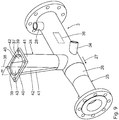
- eine perspektivische Darstellung einer Verbindungsleitung mit Fallrohr.
- Eine in
Fig. 1 bis 4 als Ganzes mit 1 gekennzeichnete Kohlenstaubverbrennungsvorrichtung umfasst eine Dosiereinheit in Form einer Zellenradschleuse 2 zum Dosieren einer Kohlenstaubmenge. Die Kohlenstaubverbrennungsvorrichtung 1 umfasst eine in den Figuren nicht dargestellte Brennereinheit zum Verbrennen der dosierten Kohlenstaubmenge. Die Kohlenstaubverbrennungsvorrichtung 1 umfasst eine Verbindungsleitung 3, die die Dosiereinheit 2 mit der Brennereinheit verbindet. - Oberhalb der Dosiereinheit 2 ist ein Zwischenbehälter 4 angeordnet. Der Zwischenbehälter 4 ist mit einem nicht dargestellten Kohlenstaubsilo verbunden. In dem Kohlenstaubsilo wird Kohlenstaub zwischengelagert und in den Zwischenbehälter 4 gefördert. Insbesondere ist das Kohlenstaubsilo oberhalb des Zwischenbehälters 4 angeordnet.
- Der Zwischenbehälter 4 ist konzentrisch zu der Zellenradschleuse 2 angeordnet. Der Zwischenbehälter 4 ist entlang der Schwerkraft, insbesondere konisch, verjüngend ausgeführt, um eine selbsttätige Förderung des Kohlenstaubs in die Zellenradschleuse 2 zu ermöglichen. Der Zwischenbehälter 4 ist mit der Zellenradschleuse 2 über eine Flanschverbindung 5 verbunden. Insbesondere ist der Zwischenbehälter 4 auf einen oberen Gehäusedeckel 31 der Zellenradschleuse 2 aufgesetzt und mittels der Flanschverbindung 5 damit verbunden.
- Im Bereich einer unteren Ausgangsöffnung 7 ist an dem Zwischenbehälter 4 ein Trennboden 6 angeordnet, der die Ausgangsöffnung 7 zumindest bereichsweise verschließt. Durch den Trennboden 6 ist der Zwischenbehälter 4 von der Zellenradschleuse 2 getrennt. Der Trennboden 6 ist durch den oberen Gehäusedeckel 31 der Zellenradschleuse 2 gebildet. Der Trennboden 6 ist gemäß dem gezeigten Ausführungsbeispiel halbkreisförmig ausgeführt und deckt im Wesentlichen die Hälfte der Ausgangsöffnung 7 ab. Über die andere Hälfte, die nicht von dem Trennboden 6 abgedeckt ist, kann Kohlenstaub unmittelbar aus dem Zwischenbehälter 4 über die Ausgangsöffnung 7 in die Zellenradschleuse 2 gelangen.
- In dem Zwischenbehälter 4 ist ein Rührwerk 8 mit mindestens einer Rührspeiche, insbesondere mit vier Rührspeichen vorgesehen. Das Rührwerk 8 lockert und befördert den Kohlenstaub gleichmäßig in die darunterliegende Zellenradschleuse 2.
- Die Zellenradschleuse 2 ist eine Vertikal-Zellenradschleuse.
- Die Zellenradschleuse 2 weist ein Zellenrad 9 auf mit zwanzig Zellenwänden 10. Die Zellenwände 10 werden auch als Rotorblätter bezeichnet. Zwischen zwei Rotorblättern 10 ist jeweils eine Zellenradkammer 11 gebildet. Das Zellenrad 9 weist zwanzig Zellenradkammern 11 auf. Die Zellenradkammern 11 sind identisch ausgeführt und weisen insbesondere eine identische Größe auf.
- Das Zellenrad 9 ist in einem Gehäuse 12 der Zellenradschleuse 2 angeordnet. Das Gehäuse 12 ist im Wesentlichen rohrzylindrisch ausgeführt, wobei die Zylinderachse vertikal orientiert ist. Das Zellenrad 9 ist in dem Gehäuse 12 um eine Drehachse 17 drehantreibbar gelagert. Die Drehachse 17 ist insbesondere identisch mit der Zylinderachse des Gehäuses 12. Die Drehachse 17 ist insbesondere vertikal orientiert.
- Die Drehachse 17 ist insbesondere identisch mit der Rührwerkachse des Rührwerks 8.
- An der oberen Flanschverbindung 5 weist das Gehäuse 12 eine Zulauföffnung 13 auf, um Kohlenstaub aus dem Zwischenbehälter 4 in die Zellenradschleuse 2 zuzuführen. Die Zulauföffnung 13 entspricht der Ausgangsöffnung 7. Insbesondere ist die Zulauföffnung 13 identisch mit der Ausgangsöffnung 7.
- An einer unteren Flanschverbindung 14 ist am Gehäuse 12 ein unterer Gehäusedeckel 15 an dem Gehäuse 12 befestigt. Der untere Gehäusedeckel 15 ist separat in
Fig. 8 dargestellt. Der untere Gehäusedeckel 15 weist eine Auslauföffnung 16 auf, durch die der Kohlenstaub aus der Zellenradschleuse 2 gleichmäßig abgegeben wird. - Das Zellenrad 9 wird von einem frequenzgeregelten Getriebemotor 18 über eine nicht dargestellte Kette, die in einem Kettengehäuse 19 läuft, angetrieben. Gemäß dem gezeigten Ausführungsbeispiel beträgt die Grundlast für den Getriebemotor etwa 1 min-1. Bei Volllast wird der Getriebemotor 18 mit 20 min-1 angetrieben.
- Das Rührwerk 8 ist starr mit dem Zellenrad 9 verbunden. Eine Drehung des Zellenrads 9 bewirkt instantan eine Drehung des Rührwerks 8.
- Der Getriebemotor 18 ist mittels einer Motorhalterung 20 gehalten.
- Im Folgenden wird anhand von
Fig. 8 die Auslauföffnung 16 näher erläutert. Die Auslauföffnung 16 ist im Wesentlichen tropfenförmig oder pfeifenförmig ausgeführt. Die Auslauföffnung 16 ist einteilig ausgeführt. Die Auslauföffnung 16 weist entlang der Drehrichtung 21 des Zellenrads 9 einen vorlaufenden Anfangsabschnitt 22 und einen nachlaufenden Endabschnitt 23 auf. - Der Anfangsabschnitt 22 weist eine Radialausdehnung rA auf, die kleiner ist als eine Radialausdehnung rE des Endabschnitts 23. Der Anfangsabschnitt 22 und der Endabschnitt 23 sind einteilig miteinander verbunden. Es ist grundsätzlich denkbar, den Anfangsabschnitt 22 von dem Endabschnitt 23 durch einen Trennsteg voneinander zu trennen. In diesem Fall wäre die Auslauföffnung 16 zweiteilig ausgeführt.
- In Drehrichtung 21 erstreckt sich der Anfangsabschnitt 22 entlang eines Drehwinkels wA. Der Endabschnitt 23 erstreckt sich in Drehrichtung um einen Drehwinkel wE. Gemäß dem gezeigten Ausführungsbeispiel beträgt der Drehwinkel wA des Anfangsabschnitts 22 15°. Der Drehwinkel wE des Endabschnitts 23 beträgt gemäß dem gezeigten Ausführungsbeispiel 30°.
- Die Radialausdehnung rA des Anfangsabschnitts 22 ist entlang der Drehrichtung 21 ansteigend, insbesondere kontinuierlich ansteigend, ausgeführt. Der Anfangsabschnitt 22 ist im Wesentlichen als ein sich in Drehrichtung 21 öffnendes U ausgeführt.
- Der Endabschnitt 23 ist in Wesentlichen kreisförmig ausgeführt.
- Die Zellenradkammern 11 sind in radialer Richtung durch das Zellenrad 9 und das Gehäuse 12 begrenzt. Die Radialausdehnung rA des Anfangsabschnitts 22 beträgt gemäß dem gezeigten Ausführungsbeispiel weniger als 50 % der Radialausdehnung rK der Zellenradkammer 11. Die Radialausdehnung rE des Endabschnitts 23 entspricht gemäß dem gezeigten Ausführungsbeispiel der Radialausdehnung rK der Zellenradkammer 11.
- Die Drehwinkelausdehnung der Zellenradkammer 11 wird auch als Kammerbreite wK bezeichnet. Gemäß dem gezeigten Ausführungsbeispiel beträgt die Kammerbreite wK 15°. Gemäß dem gezeigten Ausführungsbeispiel ist der Drehwinkel wA des Anfangsabschnitts 22 so groß wie die Kammerbreite wK. Der Drehwinkel wE des Endabschnitts 23 beträgt gemäß dem gezeigten Ausführungsbeispiel das 2-fache der Kammerbreite wK.
- An die Auslauföffnung 16 ist die Verbindungsleitung 3 angeschlossen. Die Verbindungsleitung 3 umfasst ein im Wesentlichen vertikal orientiertes Fallrohr 24 und eine Förderleitung 25. Die Förderleitung 25 ist mit dem nicht dargestellten Brenner verbunden. Die Förderleitung 25 ist im Wesentlichen horizontal angeordnet. Die Förderleitung 25 ist in dem Bereich, in dem das Fallrohr 24 angekoppelt ist, als Diffusor 26 ausgeführt. Entlang der Förderrichtung 27 verkleinert sich die Rohrquerschnittsfläche des Diffusors 26.
- Stromaufwärts bezogen auf die Förderrichtung 27 ist an den Diffusor 26 ein nicht dargestelltes Fördergebläse angeschlossen, um einen Förderluftstrom bereitzustellen.
- An die Förderleitung 25 ist eine erste Druckluftleitung 28 angeschlossen, die über eine äußere Mantelwand in den Zwischenbehälter 4 oberhalb des unteren Gehäusedeckels 15 und durch diesen hindurch geführt ist. Die erste Druckluftleitung 28 mündet in die Zellenradschleuse 2 oberhalb der Auslauföffnung 16. Insbesondere ist eine Öffnung der ersten Druckluftleitung 28 fluchtend und insbesondere konzentrisch zur Auslauföffnung 16 angeordnet.
- Über die erste Druckluftleitung 28 kann die Zellenradkammer 11, die sich im Bereich der Auslauföffnung 16 befindet, von oben mit Druckluft durchströmt werden, um eine Entleerung der Zellenradkammer 11 zu verbessern und insbesondere eine vollständige Entleerung der Zellenradkammer 11 sicherzustellen. Die erste Druckluftleitung 28 mündet in einer ersten Zuluftöffnung 29 an der Zellenradschleuse 2. Die erste Zuluftöffnung 29 ist fluchtend zu dem Endabschnitt 23 angeordnet. Die erste Zuluftöffnung 29 ist gemäß dem gezeigten Ausführungsbeispiel senkrecht zur Drehachse 17 orientiert. Die durch die erste Zuluftöffnung 29 zugeführte Förderluft ist parallel zur Drehachse 17 orientiert und ermöglicht ein verbessertes Ausblasen des Kohlenstaubs. Der Kohlenstaub wird vertikal, also parallel zur Drehachse 17, aus der Zellenradschleuse 2 gefördert.
- Ferner ist an die Zellenradschleuse eine zweite Druckluftleitung 30 angeschlossen. Die zweite, zusätzliche Druckluftleitung 30 wird durch eine seitliche Öffnung im oberen Gehäusedeckel 31 der Zellenradschleuse 2 geführt. In dem oberen Gehäusedeckel 31 ist eine zweite Zuluftöffnung 32 vorgesehen. Die zweite Zuluftöffnung 32 ist gemäß dem gezeigten Ausführungsbespiel senkrecht zur Drehachse 17 orientiert, so dass die über die zweite Druckluftleitung 30 zugeführte Luft von oben in die jeweilige Zellenradkammer 11 strömt. Die zweite Zuluftöffnung 32 ist fluchtend zu der Auslauföffnung 16, insbesondere zu dem Anfangsabschnitt 22, angeordnet.
- Entlang der Drehrichtung 21 ist die zweite Zuluftöffnung 32 vor der ersten Zuluftöffnung 29 angeordnet. Gemäß dem gezeigten Ausführungsbeispiel ist die zweite Zuluftöffnung 32 mit einem Drehwinkel w bezüglich der Drehachse 17 von 15° vor der ersten Zuluftöffnung 29 angeordnet. Insbesondere beträgt der Drehwinkelversatz zwischen der zweiten Zuluftöffnung 32 und der ersten Zuluftöffnung 29 der Kammerbreite wK, also gemäß dem gezeigten Ausführungsbeispiel 15°. Insbesondere entspricht der Drehwinkelversatz zwischen der zweiten Zuluftöffnung 32 und der ersten Zuluftöffnung 29 dem Drehwinkel wA des Anfangsabschnitts 22. Insbesondere beträgt der Drehwinkelversatz mindestens 80 % des Drehwinkels wA des Anfangsabschnitts 22, insbesondere mindestens 90 % des Drehwinkels wA des Anfangsabschnitts 22 und mindestens 95 % des Drehwinkels wA des Anfangsabschnitts 22. Dadurch ist gewährleistet, dass die über den Anfangsabschnitt 22 abzugebende Kohlenstaubmenge abgegeben worden ist, bevor die zu entleerende Zellenradkammer 11 von dem Anfangsabschnitt 22 zu dem Endabschnitt 23 geführt wird.
- An einer äußeren Zylindermantelfläche des Gehäuses 12 des Zellenrads 2 ist eine Absaugöffnung 33 angeordnet, an die eine Absaugleitung 34 angeschlossen ist. Über die Absaugöffnung 33 und die Absaugleitung 34 kann Leckluft aus der Zellenradschleuse 2 abgesaugt werden, die bei der Drehbewegung des Zellenrades 9 entstanden ist. Die Leckluft wird insbesondere aus der Zellenradkammer 11 abgesaugt, bevor die Zellenradkammer 11 wieder mit Kohlenstaub aus dem Zwischenbehälter 4 befüllt wird.
- Bezogen auf die Drehachse 17 ist die Absaugöffnung 33 der ersten Zuluftöffnung 29 und der zweiten Zuluftöffnung 32 nachgeordnet.
- In die Absaugleitung 34 ist eine Venturi-Düse 35 integriert, um den Absaugvorgang der Leckluft aus der Zellenradschleuse 2 zu begünstigen. An einem der Zellenradschleuse 2 abgewandten Ende mündet die Absaugleitung 34 in die Förderleitung 25. Die Absaugleitung 34 mündet in die Förderleitung 34 bezogen auf die Förderrichtung 27 in dem Bereich, in dem das Fallrohr 24 in die Förderleitung 25 mündet. Bezogen auf die Förderrichtung 27 ist die erste Druckluftleitung 28 stromaufwärts des Fallrohrs 24 und der Absaugleitung 34 an der Förderleitung 25 angeschlossen.
- In der Förderleitung 25 ist ein Injektor 36 integriert. Der Injektor 36 ist bezogen auf die Förderrichtung 27 bezüglich des Fallrohrs 24 und der Mündung der Absaugleitung 34 in die Förderleitung 25 stromaufwärts angeordnet. Der Injektor 36 ist bezogen auf die Förderrichtung 27 stromabwärts bezüglich des Anschlusses der ersten Druckluftleitung 28 in der Förderleitung 25 angeordnet.
- Nachfolgend wird anhand der
Fig. 9 die Förderleitung 25 mit dem Fallrohr 24 näher erläutert. Das Fallrohr 24 weist eine obere, der Zellenradschleuse 2 zugewandte Anschlussplatte 37 auf. Mit der Anschlussplatte 37 ist das Fallrohr 24 an die Zellenradschleuse 2, insbesondere am unteren Gehäusedeckel 15 im Bereich der Auslauföffnung 16 befestigt, insbesondere angeflanscht. - Im Bereich der Anschlussplatte 37 weist das Fallrohr 24 eine im Wesentlichen langlochförmige Querschnittsform auf. Die langlochförmige Kontur der Förderquerschnittsfläche des Fallrohrs 24 umfasst zwei gegenüberliegend angeordnete Halbkreisbögen 39, die durch zwei dazwischenliegende Geradabschnitte 40 miteinander verbunden sind. Die Querschnittsfläche des Fallrohrs 24 ist größer als die Auslauföffnung 16. Insbesondere ist die Auslauföffnung 16 vollständig durch die Querschnittsfläche des Fallrohrs 24 im Bereich der Anschlussplatte 37 abgedeckt. Sämtlicher, über die Auslauföffnung 16 aus der Zellenradschleuse 2 abgegebener Kohlenstaub gelangt unmittelbar in das Fallrohr 24. Das Fallrohr 24 weist eine Rohrlängsachse 38 auf, die vertikal orientiert ist. Eine Förderquerschnittsfläche des Fallrohrs 24 nimmt entlang der nach unten gerichteten Förderrichtung kontinuierlich ab.
- Die Förderquerschnittsfläche weist insbesondere eine langlochförmige, runde oder ovale Kontur auf. Insbesondere ist die Außenkontur der Förderquerschnittsfläche konvex ausgeführt. Insbesondere ist die Rutschfläche des Fallrohrs 24 rinnenartig ausgeführt.
- Insbesondere ist das Fallrohr 24 unmittelbar an die Förderleitung 25 angeschlossen. Im Bereich der Verbindung des Fallrohrs 24 an die Förderleitung 25 findet insbesondere eine Umlenkung des Kohlenstaubstroms entlang der Verbindungsleitung 3 statt, insbesondere eine 90°-Umlenkung. Die Förderleitung 25 und das Fallrohr 24 bilden insbesondere ein T-Stück.
- Die Förderquerschnittsfläche ist doppelsymmetrisch ausgeführt, wobei eine erste Symmetrieachse senkrecht zu den Geradabschnitten 40 und die zweite Symmetrieachse senkrecht zu der ersten Symmetrieachse verläuft.
- Die Kontur der Förderquerschnittsfläche ist insbesondere knickfrei ausgeführt. Das Risiko eines Anhaftens von Kohlenstaub in Knickbereichen des Fallrohrs 24 ist vermieden. Die kreisbogenförmigen Konturabschnitte des Fallrohrs 24 sind durch zwei Halbrohre 41 ausgeführt, die durch zwei dreieckförmige Blecheinsätze 42 miteinander verbunden sind. Die beiden Halbrohre 41 sind mit einem Neigungswinkel m zueinander orientiert. Der Neigungswinkel m beträgt gemäß dem gezeigten Ausführungsbeispiel 10°. Vorteilhafterweise ist der Neigungswinkel m in einem Bereich zwischen 2° und 30°, insbesondere in einem Bereich von 5° bis 20° festgelegt.
- Insbesondere ist mindestens eines der Halbrohre 41 gegenüber der Vertikalen geneigt. Dieses gegenüber der Vertikalen geneigt angeordnete Halbrohr 41 weist an seiner Innenseite eine Rutschfläche 43 für den Kohlenstaub auf. Die Rutschfläche ist rinnenartig ausgeführt und weist insbesondere eine Halbkreiskontur auf.
- Nachfolgend wird die Funktionsweise der Kohlenstaubverbrennungsvorrichtung 1 näher erläutert. Aus dem nicht dargestellten Kohlenstaubsilo wird Braunkohlestaub in den Zwischenbehälter 4 abgegeben. Mittels des Rührwerks 8 wird der Kohlenstaub in dem Zwischenbehälter 4 gelockert. Der gelockerte Kohlenstaub wird mittels des Rührwerks 8 durch die Zulauföffnung 13 im oberen Gehäusedeckel 31 in die Zellenradschleuse 2 gefördert und auf die Zellenradkammern 11, die sich unterhalb der Zulauföffnung 13 befinden, gefüllt.
- Das Zellenrad 9 wird über den Getriebemotor 18 und die im Kettengehäuse 19 angeordnete Kette angetrieben. Der Getriebemotor 18 ist frequenzgeregelt. Je höher die Drehzahl des Getriebemotors 18, also je höher die Drehzahl des Zellenrads 2, desto größer ist der Massedurchsatz von Kohlenstaub durch die Zellenradschleuse 2 und damit die zugeführte Kohlenstaubmenge in den Brenner. Durch die Drehbewegung des Zellenrads 9 entlang der Drehrichtung 21 wird der Kohlenstaub in den Zellenradkammern 11 zu der Auslauföffnung 16 gefördert. Über die zweite Zuluftöffnung 32 wird im Bereich des Anfangsabschnitts 22 Druckluft zugeführt. Dadurch ist gewährleistet, dass der Kohlenstaub in Bewegung versetzt wird und damit fließfähig bleibt. Ein Zusetzen des Kohlenstaubs ist vermieden. Dadurch, dass der Anfangsabschnitt 22 eine vergleichsweise kleine Radialausdehnung rA aufweist, kann der Kohlenstaub gleichmäßig über die Auslauföffnung 16 aus der Zellenradschleuse 2 in das Fallrohr 24 abgegeben werden. Dieser Zustand ist in
Fig. 5 dargestellt. - Durch eine weitere Drehbewegung des Zellenrads 9, die in
Fig. 6 und7 dargestellt ist, wird der Kohlenstaub weiterhin und kontinuierlich durch den Anfangsabschnitt 22 der Auslauföffnung 16 abgegeben. Durch die Zuführung von Druckluft über die erste Zuluftöffnung 29 ist gewährleistet, dass die Zellenradkammer 11 von oben mit Druckluft durchströmt wird. Die Zellenradkammer 11 der Zellenradschleuse 2 wird vollständig entleert. Gemäß einer weiteren Drehbewegung des Zellenrads 9 in Drehrichtung 21 wird der restliche, noch in der Zellenradkammer 11 befindliche Kohlenstaub über den Endabschnitt 23 in das Fallrohr 24 abgegeben. Dadurch, dass die Radialausdehnung des Endabschnitts 23 im Wesentlichen der Radialausdehnung der Zellenradkammer 11 entspricht, wird die vollständige Entleerung der Zellenradkammer 11 vereinfacht. - Die Druckluftmenge, die über die erste Druckluftleitung 28 und/oder über die zweite Druckluftleitung 30 zugeführt wird, ist veränderlich einstellbar.
- Die durch die Entleerung der Zellenradkammer 11 entstandene Leckluft wird aus der jeweiligen Zellenradkammer 11 über die Absaugöffnung 33 und die Absaugleitung 34 aus der Zellenradschleuse 2 abgesaugt und der Förderleitung 25 zugeführt. Das Absaugverhalten ist durch die in der Absaugleitung 34 integrierte Venturi-Düse 35 verbessert. Durch die Venturi-Düse 35 wird in der Absaugleitung 34 ein Sogstrom erzeugt.
- Dadurch, dass der aus der Zellenradschleuse 2 abgegebene Kohlenstaub auf die Rutschfläche 43 des Fallrohrs 24 trifft, dient das Fallrohr 24 als Rutsche. Dadurch ist verhindert, dass der abgegebene Kohlenstaub ungebremst vertikal nach unten in die Förderleitung 25 fällt. Der Kohlenstaub wird durch die geneigte Rutschfläche 43 des Fallrohrs 24 gezielt und gleichmäßig an der Förderleitung 25 aufgegeben.
- Der über das Fallrohr 24 der Förderleitung 25 aufgegebene Kohlenstaub und die über die Absaugleitung 34 abgesaugte Leckluft gelangen in der Förderleitung 25 in den Injektor 36, der insbesondere eine nicht dargestellte Injektordüse aufweist. Durch die von dem nicht dargestellten Fördergebläse erzeugte Förderluft wird der Kohlenstaub entlang der Förderrichtung 27 durch die Förderleitung 25 dem nicht dargestellten Brenner zugeführt.
- Die Kohlenstaubverbrennungsvorrichtung 1 gewährleistet eine gleichmäßige und kontinuierliche Zuführung von Kohlenstaub aus der Zellenradschleuse 2 in den Brenner 3.
Claims (10)
- Zellenradschleuse zur Kohlenstaubdosierung für einen Brenner umfassenda. ein Gehäuse (12) mit einer Zulauföffnung (13) zum Zuführen von Kohlenstaub in die Zellenradschleuse (2),b. eine Auslauföffnung (16) zur Abgabe von Kohlenstaub aus der Zellenradschleuse (2),c. ein in dem Gehäuse (12) um eine Drehachse (17) entlang einer Drehrichtung (21) drehantreibbar gelagertes Zellenrad (9),wobei die Auslauföffnung (16) eine Kontur derart aufweist, dass die Abgabe des Kohlenstaubs aus der Zellenradschleuse (2) gleichmäßig erfolgt.
- Zellenradschleuse gemäß Anspruch 1, dadurch gekennzeichnet, dass die Kontur einen in Drehrichtung (21) vorlaufenden Anfangsabschnitt (22) aufweist, dessen Radialausdehnung (rA) in Bezug auf die Drehachse (17) kleiner ist als eine Radialausdehnung (rE) eines in Drehrichtung (21) nachlaufenden Endabschnitts (23).
- Zellenradschleuse gemäß Anspruch 2, dadurch gekennzeichnet, dass die Radialausdehnung (rA) des Anfangsabschnitts (22) entlang der Drehrichtung (21), insbesondere kontinuierlich, ansteigt.
- Zellenradschleuse gemäß Anspruch 2 oder 3, dadurch gekennzeichnet, dass der Endabschnitt (23) kreisförmig ausgeführt ist.
- Zellenradschleuse gemäß einem der Ansprüche 2 bis 4, dadurch gekennzeichnet, dass der Anfangsabschnitt (22) sich entlang eines Drehwinkels (wA) erstreckt, der mindestens 50% einer Kammerbreite (wK) einer Zellenradkammer (11) beträgt.
- Zellenradschleuse gemäß einem der Ansprüche 2 bis 5, dadurch gekennzeichnet, dass der Endabschnitt (23) sich entlang eines Drehwinkels (wE) erstreckt, der mindestens 100% einer Kammerbreite (wK) einer Zellenradkammer (11) beträgt.
- Zellenradschleuse gemäß einem der Ansprüche 2 bis 6, dadurch gekennzeichnet, dass die Radialausdehnung (rA) des Anfangsabschnitts (22) kleiner ist als 50% der Radialausdehnung (rE) einer Zellenradkammer (11).
- Zellenradschleuse gemäß einem der Ansprüche 2 bis 7, dadurch gekennzeichnet, dass die Radialausdehnung (rE) des Endabschnitts (23) größer ist als 70% der Radialausdehnung (rK) der Zellenradkammer (11).
- Zellenradschleuse gemäß einem der vorstehenden Ansprüche, dadurch gekennzeichnet, dass die Kontur der Auslauföffnung (16) tropfenförmig oder pfeifenförmig ausgeführt ist.
- Zellenradschleuse gemäß einem der vorstehenden Ansprüche, dadurch gekennzeichnet, dass die Auslauföffnung (16) in einem unteren Gehäusedeckel (15) der Zellenradschleuse (2) angeordnet ist.
Priority Applications (1)
| Application Number | Priority Date | Filing Date | Title |
|---|---|---|---|
| PL20164104T PL3726134T3 (pl) | 2019-04-18 | 2020-03-19 | Śluza celkowa do dozowania miału węglowego do palnika |
Applications Claiming Priority (1)
| Application Number | Priority Date | Filing Date | Title |
|---|---|---|---|
| DE102019205732.2A DE102019205732A1 (de) | 2019-04-18 | 2019-04-18 | Zellenradschleuse zur Kohlenstaubdosierung für einen Brenner |
Publications (3)
| Publication Number | Publication Date |
|---|---|
| EP3726134A1 true EP3726134A1 (de) | 2020-10-21 |
| EP3726134B1 EP3726134B1 (de) | 2021-11-03 |
| EP3726134B8 EP3726134B8 (de) | 2021-12-15 |
Family
ID=69846268
Family Applications (1)
| Application Number | Title | Priority Date | Filing Date |
|---|---|---|---|
| EP20164104.0A Active EP3726134B8 (de) | 2019-04-18 | 2020-03-19 | Zellenradschleuse zur kohlenstaubdosierung für einen brenner |
Country Status (4)
| Country | Link |
|---|---|
| EP (1) | EP3726134B8 (de) |
| DE (1) | DE102019205732A1 (de) |
| HU (1) | HUE057750T2 (de) |
| PL (1) | PL3726134T3 (de) |
Citations (5)
| Publication number | Priority date | Publication date | Assignee | Title |
|---|---|---|---|---|
| US1772290A (en) * | 1926-05-01 | 1930-08-05 | Int Comb Eng Corp | Apparatus for feeding pulverized fuel to furnaces |
| US1844172A (en) | 1928-03-22 | 1932-02-09 | American Smelting Refining | Feeder for pulverized material |
| DE10117187C1 (de) * | 2001-04-05 | 2002-06-06 | Energieberatunsbuero Hess Gmbh | Brennstoffdosiereinrichtung mit einer Zellenradschleuse und Zellenradschleuse |
| EP2231343B1 (de) | 2007-12-20 | 2016-11-16 | Univation Technologies, LLC | Drehzufuhr- und abscheidvorrichtung und verwendungsverfahren dafür |
| CN106429456A (zh) * | 2016-10-31 | 2017-02-22 | 安徽中创电子信息材料有限公司 | 一种用于气体输送粉体的下料阀 |
Family Cites Families (1)
| Publication number | Priority date | Publication date | Assignee | Title |
|---|---|---|---|---|
| GB570796A (en) * | 1944-03-03 | 1945-07-23 | Norman Wignall | Improvements in boiler furnaces of the gravity fuel feed type |
-
2019
- 2019-04-18 DE DE102019205732.2A patent/DE102019205732A1/de not_active Ceased
-
2020
- 2020-03-19 HU HUE20164104A patent/HUE057750T2/hu unknown
- 2020-03-19 EP EP20164104.0A patent/EP3726134B8/de active Active
- 2020-03-19 PL PL20164104T patent/PL3726134T3/pl unknown
Patent Citations (5)
| Publication number | Priority date | Publication date | Assignee | Title |
|---|---|---|---|---|
| US1772290A (en) * | 1926-05-01 | 1930-08-05 | Int Comb Eng Corp | Apparatus for feeding pulverized fuel to furnaces |
| US1844172A (en) | 1928-03-22 | 1932-02-09 | American Smelting Refining | Feeder for pulverized material |
| DE10117187C1 (de) * | 2001-04-05 | 2002-06-06 | Energieberatunsbuero Hess Gmbh | Brennstoffdosiereinrichtung mit einer Zellenradschleuse und Zellenradschleuse |
| EP2231343B1 (de) | 2007-12-20 | 2016-11-16 | Univation Technologies, LLC | Drehzufuhr- und abscheidvorrichtung und verwendungsverfahren dafür |
| CN106429456A (zh) * | 2016-10-31 | 2017-02-22 | 安徽中创电子信息材料有限公司 | 一种用于气体输送粉体的下料阀 |
Also Published As
| Publication number | Publication date |
|---|---|
| EP3726134B1 (de) | 2021-11-03 |
| DE102019205732A1 (de) | 2020-10-22 |
| HUE057750T2 (hu) | 2022-06-28 |
| EP3726134B8 (de) | 2021-12-15 |
| PL3726134T3 (pl) | 2022-04-25 |
Similar Documents
| Publication | Publication Date | Title |
|---|---|---|
| EP0346278B1 (de) | Vorrichtung zum Benetzen von Saatgut | |
| DE60121038T2 (de) | Inline sichtvorrichtung | |
| DE2838445C3 (de) | Pneumatisch betriebene Maschine zum Verteilen von körnigem Gut | |
| DE19629945C2 (de) | Mischvorrichtung zum Vermischen eines pulverförmigen und/oder körnigen Feststoffes mit einer Flüssigkeit | |
| DE2720340C3 (de) | Verfahren und Vorrichtung zum Abscheiden von Faserflocken aus einem Transportluftstrom in einen Ablagerungsschacht | |
| DE2407657C3 (de) | Vorrichtung zum kontinuierlichen Mischen eines Baustoffs mit Wasser | |
| DE19937557C2 (de) | Vorrichtung zum Erzeugen eines Puder-Luft-Gemisches | |
| EP3726134B1 (de) | Zellenradschleuse zur kohlenstaubdosierung für einen brenner | |
| EP3726135A1 (de) | Dosiervorrichtung für kohlenstaub | |
| DE102024109130B4 (de) | Vorrichtung zum Zuführen von Schüttgut in eine Förderleitung, in dem das zugeführte Schüttgut pneumatisch gefördert wird | |
| DE19707165A1 (de) | Vorrichtung und Verfahren zum Vermischen eines ersten Fluids mit einem zweiten Fluid | |
| DE3006438C2 (de) | Verfahren zum Beschicken eines kontinuierlich arbeitenden Mischers und kontinuierlich arbeitender Mischer | |
| EP3423203B1 (de) | Vorrichtung und verfahren zum gemeinsamen eintragen von kunststoffteilchen und einer flüssigkeit in eine reinigungsvorrichtung | |
| EP3726133A1 (de) | Kohlenstaubverbrennungsvorrichtung | |
| DE3101221C2 (de) | "Einrichtung zur Schaumflotation" | |
| DE102008022279B4 (de) | Strahlpumpe und Verfahren zum Betrieb einer Strahlpumpe | |
| AT506149A1 (de) | Fördervorrichtung für kleinteile | |
| EP1056534B1 (de) | Mischquirl für eine mischeinrichtung | |
| DE202012102964U1 (de) | Vorreiniger für körniges Schüttgut, insbesondere Getreide | |
| WO2023147927A1 (de) | Zellenradschleuse | |
| EP3985151A1 (de) | Spinnereivorbereitungsmaschine | |
| DE102024004483A1 (de) | Vorrichtung zum Zuführen von Schüttgut in eine Förderleitung, in dem das zugeführte Schüttgut pneumatisch gefördert wird | |
| DE3727350C2 (de) | Vorrichtung zum Austrag von Flüssigkeiten in der Landwirtschaft, insbesondere von Gülle od. dgl. | |
| DE3706008C2 (de) | ||
| CH657600A5 (de) | Foerderanlage. |
Legal Events
| Date | Code | Title | Description |
|---|---|---|---|
| PUAI | Public reference made under article 153(3) epc to a published international application that has entered the european phase |
Free format text: ORIGINAL CODE: 0009012 |
|
| STAA | Information on the status of an ep patent application or granted ep patent |
Free format text: STATUS: THE APPLICATION HAS BEEN PUBLISHED |
|
| AK | Designated contracting states |
Kind code of ref document: A1 Designated state(s): AL AT BE BG CH CY CZ DE DK EE ES FI FR GB GR HR HU IE IS IT LI LT LU LV MC MK MT NL NO PL PT RO RS SE SI SK SM TR |
|
| AX | Request for extension of the european patent |
Extension state: BA ME |
|
| STAA | Information on the status of an ep patent application or granted ep patent |
Free format text: STATUS: REQUEST FOR EXAMINATION WAS MADE |
|
| STAA | Information on the status of an ep patent application or granted ep patent |
Free format text: STATUS: EXAMINATION IS IN PROGRESS |
|
| 17P | Request for examination filed |
Effective date: 20201124 |
|
| RBV | Designated contracting states (corrected) |
Designated state(s): AL AT BE BG CH CY CZ DE DK EE ES FI FR GB GR HR HU IE IS IT LI LT LU LV MC MK MT NL NO PL PT RO RS SE SI SK SM TR |
|
| 17Q | First examination report despatched |
Effective date: 20201221 |
|
| GRAP | Despatch of communication of intention to grant a patent |
Free format text: ORIGINAL CODE: EPIDOSNIGR1 |
|
| STAA | Information on the status of an ep patent application or granted ep patent |
Free format text: STATUS: GRANT OF PATENT IS INTENDED |
|
| INTG | Intention to grant announced |
Effective date: 20210624 |
|
| GRAS | Grant fee paid |
Free format text: ORIGINAL CODE: EPIDOSNIGR3 |
|
| GRAA | (expected) grant |
Free format text: ORIGINAL CODE: 0009210 |
|
| STAA | Information on the status of an ep patent application or granted ep patent |
Free format text: STATUS: THE PATENT HAS BEEN GRANTED |
|
| AK | Designated contracting states |
Kind code of ref document: B1 Designated state(s): AL AT BE BG CH CY CZ DE DK EE ES FI FR GB GR HR HU IE IS IT LI LT LU LV MC MK MT NL NO PL PT RO RS SE SI SK SM TR |
|
| REG | Reference to a national code |
Ref country code: GB Ref legal event code: FG4D Free format text: NOT ENGLISH |
|
| REG | Reference to a national code |
Ref country code: AT Ref legal event code: REF Ref document number: 1444272 Country of ref document: AT Kind code of ref document: T Effective date: 20211115 Ref country code: CH Ref legal event code: EP |
|
| REG | Reference to a national code |
Ref country code: DE Ref legal event code: R096 Ref document number: 502020000317 Country of ref document: DE |
|
| REG | Reference to a national code |
Ref country code: DE Ref legal event code: R081 Ref document number: 502020000317 Country of ref document: DE Owner name: BENNINGHOVEN ZWEIGNIEDERLASSUNG DER WIRTGEN MI, DE Free format text: FORMER OWNER: BENNINGHOVEN GMBH & CO. KG, 54516 WITTLICH, DE |
|
| REG | Reference to a national code |
Ref country code: IE Ref legal event code: FG4D Free format text: LANGUAGE OF EP DOCUMENT: GERMAN |
|
| RAP2 | Party data changed (patent owner data changed or rights of a patent transferred) |
Owner name: BENNINGHOVEN ZWEIGNIEDERLASSUNG DER WIRTGEN MINERAL TECHNOLOGIES GMBH |
|
| REG | Reference to a national code |
Ref country code: FI Ref legal event code: FGE |
|
| REG | Reference to a national code |
Ref country code: NL Ref legal event code: FP |
|
| REG | Reference to a national code |
Ref country code: LT Ref legal event code: MG9D |
|
| PG25 | Lapsed in a contracting state [announced via postgrant information from national office to epo] |
Ref country code: RS Free format text: LAPSE BECAUSE OF FAILURE TO SUBMIT A TRANSLATION OF THE DESCRIPTION OR TO PAY THE FEE WITHIN THE PRESCRIBED TIME-LIMIT Effective date: 20211103 Ref country code: LT Free format text: LAPSE BECAUSE OF FAILURE TO SUBMIT A TRANSLATION OF THE DESCRIPTION OR TO PAY THE FEE WITHIN THE PRESCRIBED TIME-LIMIT Effective date: 20211103 Ref country code: BG Free format text: LAPSE BECAUSE OF FAILURE TO SUBMIT A TRANSLATION OF THE DESCRIPTION OR TO PAY THE FEE WITHIN THE PRESCRIBED TIME-LIMIT Effective date: 20220203 |
|
| PG25 | Lapsed in a contracting state [announced via postgrant information from national office to epo] |
Ref country code: IS Free format text: LAPSE BECAUSE OF FAILURE TO SUBMIT A TRANSLATION OF THE DESCRIPTION OR TO PAY THE FEE WITHIN THE PRESCRIBED TIME-LIMIT Effective date: 20220303 Ref country code: SE Free format text: LAPSE BECAUSE OF FAILURE TO SUBMIT A TRANSLATION OF THE DESCRIPTION OR TO PAY THE FEE WITHIN THE PRESCRIBED TIME-LIMIT Effective date: 20211103 Ref country code: PT Free format text: LAPSE BECAUSE OF FAILURE TO SUBMIT A TRANSLATION OF THE DESCRIPTION OR TO PAY THE FEE WITHIN THE PRESCRIBED TIME-LIMIT Effective date: 20220303 Ref country code: NO Free format text: LAPSE BECAUSE OF FAILURE TO SUBMIT A TRANSLATION OF THE DESCRIPTION OR TO PAY THE FEE WITHIN THE PRESCRIBED TIME-LIMIT Effective date: 20220203 Ref country code: LV Free format text: LAPSE BECAUSE OF FAILURE TO SUBMIT A TRANSLATION OF THE DESCRIPTION OR TO PAY THE FEE WITHIN THE PRESCRIBED TIME-LIMIT Effective date: 20211103 Ref country code: HR Free format text: LAPSE BECAUSE OF FAILURE TO SUBMIT A TRANSLATION OF THE DESCRIPTION OR TO PAY THE FEE WITHIN THE PRESCRIBED TIME-LIMIT Effective date: 20211103 Ref country code: GR Free format text: LAPSE BECAUSE OF FAILURE TO SUBMIT A TRANSLATION OF THE DESCRIPTION OR TO PAY THE FEE WITHIN THE PRESCRIBED TIME-LIMIT Effective date: 20220204 Ref country code: ES Free format text: LAPSE BECAUSE OF FAILURE TO SUBMIT A TRANSLATION OF THE DESCRIPTION OR TO PAY THE FEE WITHIN THE PRESCRIBED TIME-LIMIT Effective date: 20211103 |
|
| REG | Reference to a national code |
Ref country code: HU Ref legal event code: AG4A Ref document number: E057750 Country of ref document: HU |
|
| PG25 | Lapsed in a contracting state [announced via postgrant information from national office to epo] |
Ref country code: SM Free format text: LAPSE BECAUSE OF FAILURE TO SUBMIT A TRANSLATION OF THE DESCRIPTION OR TO PAY THE FEE WITHIN THE PRESCRIBED TIME-LIMIT Effective date: 20211103 Ref country code: EE Free format text: LAPSE BECAUSE OF FAILURE TO SUBMIT A TRANSLATION OF THE DESCRIPTION OR TO PAY THE FEE WITHIN THE PRESCRIBED TIME-LIMIT Effective date: 20211103 Ref country code: DK Free format text: LAPSE BECAUSE OF FAILURE TO SUBMIT A TRANSLATION OF THE DESCRIPTION OR TO PAY THE FEE WITHIN THE PRESCRIBED TIME-LIMIT Effective date: 20211103 |
|
| REG | Reference to a national code |
Ref country code: DE Ref legal event code: R097 Ref document number: 502020000317 Country of ref document: DE |
|
| PLBE | No opposition filed within time limit |
Free format text: ORIGINAL CODE: 0009261 |
|
| STAA | Information on the status of an ep patent application or granted ep patent |
Free format text: STATUS: NO OPPOSITION FILED WITHIN TIME LIMIT |
|
| 26N | No opposition filed |
Effective date: 20220804 |
|
| REG | Reference to a national code |
Ref country code: FI Ref legal event code: MAE |
|
| PG25 | Lapsed in a contracting state [announced via postgrant information from national office to epo] |
Ref country code: RO Free format text: LAPSE BECAUSE OF NON-PAYMENT OF DUE FEES Effective date: 20211103 Ref country code: MC Free format text: LAPSE BECAUSE OF FAILURE TO SUBMIT A TRANSLATION OF THE DESCRIPTION OR TO PAY THE FEE WITHIN THE PRESCRIBED TIME-LIMIT Effective date: 20211103 Ref country code: FI Free format text: LAPSE BECAUSE OF NON-PAYMENT OF DUE FEES Effective date: 20220319 Ref country code: AL Free format text: LAPSE BECAUSE OF FAILURE TO SUBMIT A TRANSLATION OF THE DESCRIPTION OR TO PAY THE FEE WITHIN THE PRESCRIBED TIME-LIMIT Effective date: 20211103 |
|
| PG25 | Lapsed in a contracting state [announced via postgrant information from national office to epo] |
Ref country code: SI Free format text: LAPSE BECAUSE OF FAILURE TO SUBMIT A TRANSLATION OF THE DESCRIPTION OR TO PAY THE FEE WITHIN THE PRESCRIBED TIME-LIMIT Effective date: 20211103 |
|
| PG25 | Lapsed in a contracting state [announced via postgrant information from national office to epo] |
Ref country code: SK Free format text: LAPSE BECAUSE OF FAILURE TO SUBMIT A TRANSLATION OF THE DESCRIPTION OR TO PAY THE FEE WITHIN THE PRESCRIBED TIME-LIMIT Effective date: 20211103 Ref country code: IE Free format text: LAPSE BECAUSE OF NON-PAYMENT OF DUE FEES Effective date: 20220319 |
|
| P01 | Opt-out of the competence of the unified patent court (upc) registered |
Effective date: 20230517 |
|
| PG25 | Lapsed in a contracting state [announced via postgrant information from national office to epo] |
Ref country code: MK Free format text: LAPSE BECAUSE OF FAILURE TO SUBMIT A TRANSLATION OF THE DESCRIPTION OR TO PAY THE FEE WITHIN THE PRESCRIBED TIME-LIMIT Effective date: 20211103 Ref country code: CY Free format text: LAPSE BECAUSE OF FAILURE TO SUBMIT A TRANSLATION OF THE DESCRIPTION OR TO PAY THE FEE WITHIN THE PRESCRIBED TIME-LIMIT Effective date: 20211103 |
|
| PG25 | Lapsed in a contracting state [announced via postgrant information from national office to epo] |
Ref country code: MT Free format text: LAPSE BECAUSE OF FAILURE TO SUBMIT A TRANSLATION OF THE DESCRIPTION OR TO PAY THE FEE WITHIN THE PRESCRIBED TIME-LIMIT Effective date: 20211103 |
|
| GBPC | Gb: european patent ceased through non-payment of renewal fee |
Effective date: 20240319 |
|
| PG25 | Lapsed in a contracting state [announced via postgrant information from national office to epo] |
Ref country code: GB Free format text: LAPSE BECAUSE OF NON-PAYMENT OF DUE FEES Effective date: 20240319 |
|
| PG25 | Lapsed in a contracting state [announced via postgrant information from national office to epo] |
Ref country code: GB Free format text: LAPSE BECAUSE OF NON-PAYMENT OF DUE FEES Effective date: 20240319 |
|
| PGFP | Annual fee paid to national office [announced via postgrant information from national office to epo] |
Ref country code: AT Payment date: 20250417 Year of fee payment: 5 |
|
| PGFP | Annual fee paid to national office [announced via postgrant information from national office to epo] |
Ref country code: DE Payment date: 20250520 Year of fee payment: 6 |
|
| PGFP | Annual fee paid to national office [announced via postgrant information from national office to epo] |
Ref country code: IT Payment date: 20250331 Year of fee payment: 6 |
|
| PGFP | Annual fee paid to national office [announced via postgrant information from national office to epo] |
Ref country code: CH Payment date: 20250401 Year of fee payment: 6 |
|
| PG25 | Lapsed in a contracting state [announced via postgrant information from national office to epo] |
Ref country code: TR Free format text: LAPSE BECAUSE OF FAILURE TO SUBMIT A TRANSLATION OF THE DESCRIPTION OR TO PAY THE FEE WITHIN THE PRESCRIBED TIME-LIMIT Effective date: 20211103 |
|
| REG | Reference to a national code |
Ref country code: CH Ref legal event code: U11 Free format text: ST27 STATUS EVENT CODE: U-0-0-U10-U11 (AS PROVIDED BY THE NATIONAL OFFICE) Effective date: 20260401 |
|
| PGFP | Annual fee paid to national office [announced via postgrant information from national office to epo] |
Ref country code: LU Payment date: 20260320 Year of fee payment: 7 Ref country code: BE Payment date: 20260323 Year of fee payment: 7 |
|
| PGFP | Annual fee paid to national office [announced via postgrant information from national office to epo] |
Ref country code: HU Payment date: 20260313 Year of fee payment: 7 Ref country code: NL Payment date: 20260323 Year of fee payment: 7 |
|
| PGFP | Annual fee paid to national office [announced via postgrant information from national office to epo] |
Ref country code: FR Payment date: 20260324 Year of fee payment: 7 |
|
| PGFP | Annual fee paid to national office [announced via postgrant information from national office to epo] |
Ref country code: CZ Payment date: 20260306 Year of fee payment: 7 |
|
| PGFP | Annual fee paid to national office [announced via postgrant information from national office to epo] |
Ref country code: PL Payment date: 20260217 Year of fee payment: 7 |