EP3726237A2 - Magnetfeldsensor, system und verfahren zur geschwindigkeitsmessung - Google Patents
Magnetfeldsensor, system und verfahren zur geschwindigkeitsmessung Download PDFInfo
- Publication number
- EP3726237A2 EP3726237A2 EP20168792.8A EP20168792A EP3726237A2 EP 3726237 A2 EP3726237 A2 EP 3726237A2 EP 20168792 A EP20168792 A EP 20168792A EP 3726237 A2 EP3726237 A2 EP 3726237A2
- Authority
- EP
- European Patent Office
- Prior art keywords
- output signal
- magnetoresistive sensor
- sensor element
- magnetoresistive
- sensor elements
- Prior art date
- Legal status (The legal status is an assumption and is not a legal conclusion. Google has not performed a legal analysis and makes no representation as to the accuracy of the status listed.)
- Withdrawn
Links
- 230000005291 magnetic effect Effects 0.000 title claims abstract description 172
- 238000000034 method Methods 0.000 title claims description 23
- 238000005259 measurement Methods 0.000 title description 9
- 230000005415 magnetization Effects 0.000 claims abstract description 80
- 238000012545 processing Methods 0.000 claims abstract description 46
- 230000004044 response Effects 0.000 claims abstract description 36
- 230000006911 nucleation Effects 0.000 claims description 15
- 238000010899 nucleation Methods 0.000 claims description 15
- 239000003302 ferromagnetic material Substances 0.000 claims description 7
- 230000004888 barrier function Effects 0.000 description 14
- 230000008569 process Effects 0.000 description 14
- 239000000463 material Substances 0.000 description 12
- 238000012546 transfer Methods 0.000 description 12
- 230000008859 change Effects 0.000 description 9
- 238000010586 diagram Methods 0.000 description 6
- 230000000694 effects Effects 0.000 description 5
- 230000015572 biosynthetic process Effects 0.000 description 4
- 230000005294 ferromagnetic effect Effects 0.000 description 4
- 239000000203 mixture Substances 0.000 description 4
- 238000012986 modification Methods 0.000 description 4
- 230000004048 modification Effects 0.000 description 4
- 238000005516 engineering process Methods 0.000 description 3
- 230000005293 ferrimagnetic effect Effects 0.000 description 3
- 239000000696 magnetic material Substances 0.000 description 3
- 230000035945 sensitivity Effects 0.000 description 3
- 230000009471 action Effects 0.000 description 2
- 230000005290 antiferromagnetic effect Effects 0.000 description 2
- 238000006243 chemical reaction Methods 0.000 description 2
- 238000001514 detection method Methods 0.000 description 2
- 238000005530 etching Methods 0.000 description 2
- 230000004907 flux Effects 0.000 description 2
- 230000012447 hatching Effects 0.000 description 2
- 229910052751 metal Inorganic materials 0.000 description 2
- 239000002184 metal Substances 0.000 description 2
- 230000010363 phase shift Effects 0.000 description 2
- 239000000758 substrate Substances 0.000 description 2
- 229910000531 Co alloy Inorganic materials 0.000 description 1
- 229910019236 CoFeB Inorganic materials 0.000 description 1
- ZDZZPLGHBXACDA-UHFFFAOYSA-N [B].[Fe].[Co] Chemical compound [B].[Fe].[Co] ZDZZPLGHBXACDA-UHFFFAOYSA-N 0.000 description 1
- ZGWQKLYPIPNASE-UHFFFAOYSA-N [Co].[Zr].[Ta] Chemical compound [Co].[Zr].[Ta] ZGWQKLYPIPNASE-UHFFFAOYSA-N 0.000 description 1
- KGWWEXORQXHJJQ-UHFFFAOYSA-N [Fe].[Co].[Ni] Chemical compound [Fe].[Co].[Ni] KGWWEXORQXHJJQ-UHFFFAOYSA-N 0.000 description 1
- 229910045601 alloy Inorganic materials 0.000 description 1
- 239000000956 alloy Substances 0.000 description 1
- 239000002885 antiferromagnetic material Substances 0.000 description 1
- 230000008878 coupling Effects 0.000 description 1
- 238000010168 coupling process Methods 0.000 description 1
- 238000005859 coupling reaction Methods 0.000 description 1
- 239000013078 crystal Substances 0.000 description 1
- 238000000151 deposition Methods 0.000 description 1
- 239000012777 electrically insulating material Substances 0.000 description 1
- 239000002902 ferrimagnetic material Substances 0.000 description 1
- 239000012212 insulator Substances 0.000 description 1
- XEEYBQQBJWHFJM-UHFFFAOYSA-N iron Substances [Fe] XEEYBQQBJWHFJM-UHFFFAOYSA-N 0.000 description 1
- UGKDIUIOSMUOAW-UHFFFAOYSA-N iron nickel Chemical compound [Fe].[Ni] UGKDIUIOSMUOAW-UHFFFAOYSA-N 0.000 description 1
- 238000001459 lithography Methods 0.000 description 1
- 229960000869 magnesium oxide Drugs 0.000 description 1
- CPLXHLVBOLITMK-UHFFFAOYSA-N magnesium oxide Inorganic materials [Mg]=O CPLXHLVBOLITMK-UHFFFAOYSA-N 0.000 description 1
- 235000012245 magnesium oxide Nutrition 0.000 description 1
- 239000000395 magnesium oxide Substances 0.000 description 1
- AXZKOIWUVFPNLO-UHFFFAOYSA-N magnesium;oxygen(2-) Chemical compound [O-2].[Mg+2] AXZKOIWUVFPNLO-UHFFFAOYSA-N 0.000 description 1
- TWNQGVIAIRXVLR-UHFFFAOYSA-N oxo(oxoalumanyloxy)alumane Chemical compound O=[Al]O[Al]=O TWNQGVIAIRXVLR-UHFFFAOYSA-N 0.000 description 1
- 238000000059 patterning Methods 0.000 description 1
- 229910000889 permalloy Inorganic materials 0.000 description 1
- 238000004886 process control Methods 0.000 description 1
- 230000006641 stabilisation Effects 0.000 description 1
- 238000011105 stabilization Methods 0.000 description 1
Images


Classifications
-
- G—PHYSICS
- G01—MEASURING; TESTING
- G01R—MEASURING ELECTRIC VARIABLES; MEASURING MAGNETIC VARIABLES
- G01R33/00—Arrangements or instruments for measuring magnetic variables
- G01R33/02—Measuring direction or magnitude of magnetic fields or magnetic flux
- G01R33/06—Measuring direction or magnitude of magnetic fields or magnetic flux using galvano-magnetic devices
- G01R33/09—Magnetoresistive devices
- G01R33/091—Constructional adaptation of the sensor to specific applications
-
- G—PHYSICS
- G01—MEASURING; TESTING
- G01R—MEASURING ELECTRIC VARIABLES; MEASURING MAGNETIC VARIABLES
- G01R33/00—Arrangements or instruments for measuring magnetic variables
- G01R33/02—Measuring direction or magnitude of magnetic fields or magnetic flux
- G01R33/06—Measuring direction or magnitude of magnetic fields or magnetic flux using galvano-magnetic devices
- G01R33/09—Magnetoresistive devices
- G01R33/093—Magnetoresistive devices using multilayer structures, e.g. giant magnetoresistance sensors
-
- G—PHYSICS
- G01—MEASURING; TESTING
- G01P—MEASURING LINEAR OR ANGULAR SPEED, ACCELERATION, DECELERATION, OR SHOCK; INDICATING PRESENCE, ABSENCE, OR DIRECTION, OF MOVEMENT
- G01P3/00—Measuring linear or angular speed; Measuring differences of linear or angular speeds
- G01P3/42—Devices characterised by the use of electric or magnetic means
- G01P3/44—Devices characterised by the use of electric or magnetic means for measuring angular speed
- G01P3/49—Devices characterised by the use of electric or magnetic means for measuring angular speed using eddy currents
-
- G—PHYSICS
- G01—MEASURING; TESTING
- G01P—MEASURING LINEAR OR ANGULAR SPEED, ACCELERATION, DECELERATION, OR SHOCK; INDICATING PRESENCE, ABSENCE, OR DIRECTION, OF MOVEMENT
- G01P3/00—Measuring linear or angular speed; Measuring differences of linear or angular speeds
- G01P3/42—Devices characterised by the use of electric or magnetic means
- G01P3/44—Devices characterised by the use of electric or magnetic means for measuring angular speed
- G01P3/48—Devices characterised by the use of electric or magnetic means for measuring angular speed by measuring frequency of generated current or voltage
- G01P3/481—Devices characterised by the use of electric or magnetic means for measuring angular speed by measuring frequency of generated current or voltage of pulse signals
- G01P3/487—Devices characterised by the use of electric or magnetic means for measuring angular speed by measuring frequency of generated current or voltage of pulse signals delivered by rotating magnets
-
- G—PHYSICS
- G01—MEASURING; TESTING
- G01R—MEASURING ELECTRIC VARIABLES; MEASURING MAGNETIC VARIABLES
- G01R33/00—Arrangements or instruments for measuring magnetic variables
- G01R33/0023—Electronic aspects, e.g. circuits for stimulation, evaluation, control; Treating the measured signals; calibration
-
- G—PHYSICS
- G01—MEASURING; TESTING
- G01R—MEASURING ELECTRIC VARIABLES; MEASURING MAGNETIC VARIABLES
- G01R33/00—Arrangements or instruments for measuring magnetic variables
- G01R33/02—Measuring direction or magnitude of magnetic fields or magnetic flux
- G01R33/022—Measuring gradient
-
- G—PHYSICS
- G01—MEASURING; TESTING
- G01R—MEASURING ELECTRIC VARIABLES; MEASURING MAGNETIC VARIABLES
- G01R33/00—Arrangements or instruments for measuring magnetic variables
- G01R33/02—Measuring direction or magnitude of magnetic fields or magnetic flux
- G01R33/06—Measuring direction or magnitude of magnetic fields or magnetic flux using galvano-magnetic devices
- G01R33/09—Magnetoresistive devices
- G01R33/098—Magnetoresistive devices comprising tunnel junctions, e.g. tunnel magnetoresistance sensors
-
- G—PHYSICS
- G01—MEASURING; TESTING
- G01R—MEASURING ELECTRIC VARIABLES; MEASURING MAGNETIC VARIABLES
- G01R33/00—Arrangements or instruments for measuring magnetic variables
- G01R33/0094—Sensor arrays
Definitions
- the present invention relates generally to magnetic field sensors. More specifically, the present invention relates to magnetoresistive sensors with their sense layers in a vortex state for measuring magnetic fields in a gradient configuration.
- Magnetic field sensor systems are utilized in a variety of commercial, industrial, and automotive applications to measure magnetic fields for purposes of speed and direction sensing, rotation angle sensing, proximity sensing, and the like. Some magnetic field sensors are based upon the magnetoresistive effect in which a material has a tendency to change the value of its electrical resistance in response to an externally-applied magnetic field. Magnetoresistive devices include, for example, Anisotropic Magneto Resistance (AMR) technology, Giant Magneto Resistance (GMR) technology, Tunnel Magneto Resistance (TMR) technology, and so forth.
- AMR Anisotropic Magneto Resistance
- GMR Giant Magneto Resistance
- TMR Tunnel Magneto Resistance
- a sensor comprising a first magnetoresistive sensor element configured to produce a first output signal in response to an external magnetic field, a second magnetoresistive sensor element configured to produce a second output signal in response to the external magnetic field, wherein the first and second magnetoresistive sensor elements form a gradient unit, each of the first and second magnetoresistive sensor elements includes a sense layer having a vortex magnetization pattern, and a processing circuit electrically coupled to the first and second magnetoresistive sensor elements, wherein the processing circuit is configured to produce a differential output signal as a difference between the first and second output signals of the first and second magnetoresistive sensor elements of the gradient unit.
- a system comprising an encoder configured to produce an external magnetic field having predetermined magnetic variations in response to motion of the encoder and sensor.
- the sensor comprises a first magnetoresistive sensor element configured to produce a first output signal in response to the external magnetic field, a second magnetoresistive sensor element configured to produce a second output signal in response to the external magnetic field, the first and second magnetoresistive sensor elements form a gradient unit, each of the first and second magnetoresistive sensor elements includes a sense layer having a vortex magnetization pattern, and a processing circuit electrically coupled to the first and second magnetoresistive sensor elements, wherein the processing circuit is configured to produce a differential output signal as a difference between the first and second output signals of the first and second magnetoresistive sensor elements of the gradient unit.
- the gradient unit is a first gradient unit
- the differential output signal is a first differential output signal
- the sensor further comprises: a third magnetoresistive sensor element configured to produce a third output signal in response to the external magnetic field, wherein a sense layer of the third magnetoresistive sensor element has the vortex magnetization pattern and the first and third magnetoresistive sensor elements form a second gradient unit
- the processing circuit is electrically coupled to the third magnetoresistive sensor element and is configured to: produce a second differential output signal as the difference between the second and third output signals of the second gradient unit; produce a sensor output signal as a difference between the first and second differential output signals; and generate a speed pulse indicative of a speed of an apparatus coupled to the encoder when the sensor output signal is zero.
- the system further comprises: a first detector configured to receive the first output signal from the first magnetoresistive sensor element and determine from the first output signal whether the first magnetoresistive sensor element is operating in a safe range, the safe range being less than a nucleation field for the vortex magnetization pattern; a second detector configured to receive the second output signal from the second magnetoresistive sensor element and determine from the second output signal whether the second magnetoresistive sensor element is operating in the safe range; and a third detector configured to receive the second output signal from the second magnetoresistive sensor element and determine from the second output signal whether the second magnetoresistive sensor element is operating in the safe range, wherein: the processing circuit is electrically coupled with the first, second, and third detectors, the processing circuit being further configured to: produce a first flag when the first magnetoresistive sensor element is not operating in the safe range thereby indicating that the first output signal is invalid; produce a second flag when the second magnetoresistive sensor element is not operating in the safe range thereby indicating that the second output signal is
- a method of determining speed of an apparatus comprising providing an encoder coupled to the apparatus, the encoder being configured to produce an external magnetic field having predetermined magnetic variations in response to motion of the encoder and the apparatus, producing a plurality of output signals in response to the external magnetic field at each of a plurality of magnetoresistive sensor elements, wherein each of the magnetoresistive sensor elements includes a sense layer having a vortex magnetization pattern, selecting first and second magnetoresistive sensor elements from the plurality of magnetoresistive sensor elements to be a first gradient unit, and producing a first differential output signal as a difference between the first and second output signals of the first and second magnetoresistive sensor elements of the gradient unit.
- a system includes multiple magnetoresistive sensor elements, such as tunnel magnetoresistive (TMR) sensor elements, arranged in a gradient magnetic field sensing configuration.
- the sense layers (also referred to as free layers) of the TMR sensor elements are configured in a vortex state and are thus sensitive to in-plane magnetic fields along a single axis.
- Stability of the vortex state of the sensor elements may be achieved by a combination of measures including a multi-layered sense layer with a relatively thick soft magnetic material with high saturation magnetization and a relatively small diameter of the sense layer in which a compromise is achieved between manufacturability of the layer thickness and diameter.
- stability of the sensor elements in a vortex state may be achieved by an encoder magnet and sensor layout arrangement, a second-order gradient arrangement, and the ability to detect a critical situation and flag it to the user of the sensor.
- FIG. 1 shows a simplified perspective view of a tunnel magnetoresistive (TMR) sensor element 20 having a single domain state.
- TMR sensor element 20 typically includes a layer stack 22 of alternating non-magnetic, (anti)ferromagnetic, or ferrimagnetic layers arranged on a common substrate (not shown).
- a layer stack 22 of alternating non-magnetic, (anti)ferromagnetic, or ferrimagnetic layers arranged on a common substrate (not shown).
- the layers of layer stack 22 extend in a plane spanned by X- and Y-axes 24, 26.
- a TMR structure typically includes a metal-insulator-metal layer sandwich, (e.g., layer stack 22), in which the metal layers are magnetic and the insulator layer is very thin.
- layer stack 22 of TMR sensor element 20 includes magnetic layers 30, 32 separated by an electrically insulating tunnel barrier layer 34.
- Magnetic layer 30 may be fixed, or "pinned,” to have a reference magnetization, as represented by an arrow 36. Therefore, ferromagnetic layer 30 is referred to hereinafter as reference layer 30.
- Magnetic layer 32 is "free" to respond to, i.e., sense, an applied magnetic field to provide a sense magnetization, represented by an arrow 38. Accordingly, magnetic layer 32 is referred to hereinafter as sense layer 32.
- the single domain state configuration of TMR sensor element 20 has homogeneous in-plane magnetization.
- TMR effect expresses itself as a change of the amount of charges passing through tunnel barrier layer 34 in a given time interval for a given electrical voltage across the tunnel barrier. This effect may arise due to directional changes of the magnetization of sense layer 32 caused by the changing external magnetic field. The external magnetic field or field angle can thus be sensed by a change in the conductance (or resistance) of the sensor element.
- FIG. 2 shows a graph 40 of a magnetoresistive transfer curve 42 of magnetic field strength 44, H Y , for the single domain state of the TMR sensor element 20 ( FIG. 1 ).
- magnetoresistive transfer curve 42 has an external stabilization field H X(BIAS) along X-axis 24 ( FIG. 1 ) in accordance with current magnetoresistive speed sensors for passive encoder wheels.
- Transfer curve 42 shows a generally linear response with minor hysteresis.
- the sensitivity and hence the apparently measured magnetic field 44, H Y depends upon the cross-axis magnetic field strength 46, H X1 or H X2 , in this example.
- FIG. 3 shows a simplified perspective view of a TMR sensor element 50 having a vortex state.
- TMR sensor element 50 includes a layer stack 52 that includes a magnetic reference layer 54 and a magnetic sense layer 56 separated by an electrically insulating tunnel barrier layer 58.
- reference layer 54 is fixed, or "pinned,” to have a reference magnetization, as represented by an arrow 60.
- Magnetic sense layer 56 is a rotationally symmetric circular or disk-like shape. Providing sense layer 56 having a rotationally symmetric shape may lead to formation of a closed flux magnetization pattern in sense layer 56. This closed flux magnetization pattern may include a vortex magnetization pattern, where the vortex magnetization pattern may be essentially circular.
- magnetic sense layer 56 has a vortex magnetization pattern 62 in which the magnetization is characterized by a circumferential (e.g., circular) pattern and a center point 64 (also referred to as a vortex core) at which the magnetization direction points outward or inward relative to Z-axis 28.
- a circumferential e.g., circular
- a center point 64 also referred to as a vortex core
- Layers of elliptic, polygonal, rectangular, or other shapes may also form a vortex state and behave similar to the example presented herein.
- FIG. 4 shows a top view of sense layer 56 of TMR sensor element 50 having vortex magnetization pattern 62
- FIG. 5 shows a top view of sense layer 56 of TMR sensor element 50 in which vortex magnetization pattern 62 has shifted in response to application of an external magnetic field 66 (e.g., H Y ).
- vortex magnetization pattern 62 is patterned in a circular shape, which may provide effective vortex pattern stability for isotropic layer properties. In other embodiments, this circular shape may be modified depending upon a particular application and the crystal anisotropy.
- the vortex core e.g., center point 64
- the vortex magnetization pattern 62 is centered (for example, located at the center dotted line).
- Application of external magnetic field 66 moves vortex magnetization pattern 62 perpendicular to external magnetic field 66. That is, vortex magnetization pattern 62 becomes off centered from the center dotted line and a net magnetization is generated. Schematically this net magnetization is indicated by an area 68 in FIG. 5 . Since the magnetization structure is not rigid as assumed in first-order, the net magnetic moment will depend on the micromagnetic details of sense layer 56. However, FIGs. 4 and 5 generally demonstrate the sensing principle.
- reference layer 54 ( FIG. 3 ) is magnetized parallel to Y-axis 26, then the illustrated configuration generates a conductance change that is proportional to the H Y magnetic field component. Similarly, if reference layer 54 is magnetized parallel to X-axis 24, then a conductance change will be proportional to the Hx magnetic field component.
- FIG. 6 shows a graph 70 of a magnetoresistive transfer curve 72 in dependence of magnetic field strength 74, H Y , for the vortex state of TMR sensor element 50 ( FIG. 3 ).
- Transfer curve 72 shows no cross-axis dependency in the linear range around a zero H Y magnetic field. That is, the apparent magnetic field component 74, H Y , inhered from a measurement of the conductance of TMR sensor element 50 is not affected by the cross-axis magnetic field strength, Hx.
- Critical parameters which may describe a condition in which the vortex state exists are referred to as the nucleation field, H N , where the vortex nucleates, and the annihilation field, H A , where the vortex vanishes and gets destroyed again, respectively.
- Graph 70 further shows these vortex characteristics, i.e., nucleation field, H N , and annihilation field, H A .
- a first working range referred to herein as a vortex formation range 76 is defined by the nucleation fields H N+ and H N- , and may be unaffected by the magnetic history since vortex nucleation may be ensured.
- a second working range referred to herein as a vortex annihilation range 78 is defined by the annihilation fields H A+ and H A- . As long as vortex annihilation range 78 is not exceeded (for example, by a disturbance event, such as a high magnetic field pulse), the vortex state may be preserved.
- the in-plane component of the magnetization, dR/R may be shifted along curve 72 by altering the external magnetic field.
- a "reset” may be needed in order to re-form vortex magnetization pattern 62 ( FIG. 3 ) by reducing the external magnetic field strength to a value within vortex formation range 76.
- the in-plane component of the magnetization, dR/R may follow a hysteresis curve 80, 82.
- FIG. 6 shows a typical response for a vortex (e.g., vortex magnetization pattern 62) to a linear external magnetic field.
- the vortex has limited stability.
- the vortex can be annihilated (i.e., destroyed) at a magnetic field above H A and is nucleated only at a lower magnetic field, H N , causing hysteresis.
- This limited stability hampers the use of vortex mode sensors in some applications (for example, automotive applications) with a large dynamic range of operation.
- systems include multiple magnetoresistive sensor elements, such as TMR sensor elements 50, each of which includes magnetic sense layer 56 configured to generate vortex magnetization pattern 62 in magnetic sense layer 56 and each of which is configured to produce an output signal in response to an external magnetic field, which may be produced by an encoder magnet within a system.
- Vortex state magnetoresistive sensor elements e.g., TMR sensor element 50
- FIG. 7 shows a schematic cross-section of a TMR sensor element in accordance with an embodiment. More particularly, FIG. 7 shows a schematic cross-section of TMR sensor element 50 (also referred to as a magnetic tunnel junction or MTJ) in accordance with some embodiments.
- a magnetic field sensor can include a multiplicity of TMR sensor elements 50 suitably connected together.
- TMR sensor element 50 includes multiple structural layers, and these layers can again include multiple layers.
- a TMR sensor element 50 includes a bottom contact 84, which itself may include a bottom electrode, buffer, and seed layer (not distinguished herein). Electrical connections and/or a substrate (not shown) may be located below bottom contact 84.
- a pinning layer 86 is formed on bottom contact 84 and magnetic reference layer 54 is formed on pinning layer 86.
- Pinning layer 86 may be antiferromagnetic, ferrimagnetic, or ferromagnetic material. Pinning layer 86 may also contain a synthetic antiferromagnetic or ferrimagnetic stack of layers that are magnetically coupled.
- Reference magnetization 60 ( FIG. 3 ) of reference layer 54 is pinned by couplings to pinning layer 86 so that reference magnetization 60 does not change significantly with an external magnetic field.
- Tunnel barrier layer 58 is formed on magnetic reference layer 54.
- Tunnel barrier layer 58 may be a magnesium-oxide composition (MgOx), an aluminum oxide composition (AL 2 O 3 ), or any other suitable electrically insulating material.
- Magnetic sense layer 56 may be formed on tunnel barrier layer 58.
- the performance of TMR sensor element 50 may be improved by increasing the operating field range.
- the operating field range may be increased by judicious selection of shape, thickness, and/or materials of sense layer 56.
- the operating field range becomes larger for a high saturation magnetization of the sense layer material and a high aspect ratio of the thickness to the lateral dimension (e.g., diameter) of the sense layer.
- lithography processes demand a minimum diameter (e.g., above 100 nanometers) for automotive robust configurations.
- the thickness of the sense layer should not be too thick in order to avoid issues related to mechanical stress or etching.
- sense layer 56 may be formed of layers 88, 90, 92 in some embodiments.
- the TMR effect is such that a component of the net magnetization of sense layer 56 is converted to a conductance if reference layer 54 is predominantly uniformly magnetized (e.g., single domain state, flower state, or similar).
- layer 88 in contact with tunnel barrier layer 58 may be formed of a similar material as that of reference layer 54.
- layer 88 may be optimized for highest resistance change (e.g., R max /R min -1) of the tunnel current through tunnel barrier layer 58.
- a material that may be utilized for layer 88 may be, for example, a cobalt-iron-boron (CoFeB) composition, although other suitable materials may alternatively be used.
- CoFeB cobalt-iron-boron
- layer 90 is a magnetically-soft, ferromagnetic material layer.
- a magnetically-soft, ferromagnetic material is a material in which the magnetization within the material can be easily reversed.
- the magnetically-soft ferromagnetic material layer 90 may be a cobalt-tantalum-zirconium (CoTaZr) alloy or a nickel-iron-cobalt alloy (Ni 74 Fe 10 Co 16 ) in some embodiments. These materials have a higher saturation magnetization (e.g., a maximum possible magnetization) than nickel-iron material (e.g., Permalloy) that is used in typical AMR sensors.
- these materials are uniform enough (e.g., amorphous) and contain elements that can be reasonably etched. That is, both uniformity and composition are important for a well-controlled etch process. Still further, they have low magnetostriction (e.g., a property pertaining to the change in the dimensions of a ferromagnetic body caused by a change in its state of magnetization). Low magnetostriction is important for minimizing the stress sensitivity of TMR sensor element 50.
- sense layer 56 is characterized by a shape and a size such that only a single vortex magnetization pattern 62 ( FIG. 3 ) is generated within sense layer 56 in the absence of an external magnetic field.
- sense layer 56 has a circular shape in some embodiments, as discussed above.
- the circular magnetically-soft, ferromagnetic material layer 90 may have a thickness 94 between 20 and 60 nanometers and a diameter 96 between 150 and 500 nanometers.
- sense layer 56 may have an elliptical shape in which a length of each of a major axis and a minor axis of the ellipse is between 150 and 500 nanometers.
- sense layer 56 is described as including three layers 88, 90, 92, these layers may be built up of multiple different sublayers (e.g., to control the crystalinity, to have added capping, and growth layers, and so forth). Additionally, layer stack 52 may be inverted by processing the reference layer above the tunnel barrier layer. TMR sensor elements may be advantageously implemented herein due to their high output signal. However, alternative embodiments may implement other configurations, such as AMR or GMR with a vortex state.
- FIG. 8 shows in a simplified and representative form an example of a system 100 (e.g., a speed sensor) for rotation speed measurement in which a pair of TMR sensor elements may be implemented in accordance with an embodiment.
- system 100 includes an encoder 102 configured to produce an external magnetic field 104 (represented by dashed arrows) having predetermined magnetic variations in response to rotation (denoted by curved arrow 105) of encoder 102.
- the presented alternating north (N) and south (S) pole configuration shown in FIG. 8 yields the predetermined magnetic variations.
- Alternative embodiments may implement a ferromagnetic gear wheel or other similar structure. Other possible magnetizations are possible, such as tooth-to-tooth with alternating north and south poles.
- System 100 further includes first and second magnetoresistive sensor elements.
- the first and second magnetoresistive sensor elements are equivalent to TMR sensor elements 50 ( FIG. 7 ). Therefore, they are referred to herein as a first TMR sensor element 50A and a second TMR sensor element 50B.
- each of first and second TMR sensor elements 50A and 50B includes sense layer 56 ( FIG. 7 ) having vortex magnetization pattern 62.
- a processing circuit 106 is electrically coupled to first and second TMR sensor elements 50A, 50B.
- first and second TMR sensor elements 50A, 50B are configured to measure rotational speed of encoder 102, and hence to measure the rotational speed of an apparatus to which encoder 102 is attached.
- the apparatus may be a shaft 108.
- TMR sensor elements 50 are shown in connection with system 100 and other systems described below. It should be understood, however, that each TMR sensor element may represent a single TMR sensor element, a half-bridge of TMR sensor elements, a full-bridge of TMR sensor elements, multiple TMR sensor elements in series, using reference resistors, measuring currents or voltages, and so forth. Additionally, although TMR sensor elements are discussed herein, those skilled in the art will recognize that vortex structures are not limited to the TMR effect. Alternative system embodiments may implement Giant Magnetoresistive (GMR) sensor structures, Anisotropic Magnetoresistive (AMR) sensor structures, or other xMR structures.
- GMR Giant Magnetoresistive
- AMR Anisotropic Magnetoresistive
- the high sensitivity of a TMR sensor is combined with the linearity of a vortex state sensor (e.g., vortex magnetization pattern 62) and a gradient sensing principle.
- system 100 employs a first-order gradient sensing configuration. That is, encoder 102 produces external magnetic field 104 having a component, H Y , that is oriented in the plane (defined by X- and Y-axes 24, 26) of sense layer 56, and a component, Hz, that is oriented perpendicular to the plane of sense layer 56.
- first and second sensor elements 50A, 50B only react to the magnetic field component, H Y , in the plane of sense layer 56.
- first and second TMR sensor elements 50A, 50B are aligned with Y-axis 26 to detect a component of external magnetic field 104, H Y , that is oriented in a first direction in the plane of sense layer 56 (e.g., and more particularly, parallel to Y-axis 26).
- the Y-axis component of external magnetic field 104, H Y is referred to herein as Y-axis external magnetic field 110.
- system 100 includes a gradient unit 112 that includes first and second TMR sensor elements 50A, 50B.
- First TMR sensor element 50A is configured to produce a first output signal 114, Ho, in response to Y-axis external magnetic field 110.
- second TMR sensor element 50B is configured to produce a second output signal 116, H+i, in response to Y-axis external magnetic field 110.
- First and second output signals 114, 116 may be input to processing circuit 106.
- processing circuit 106 may be a difference unit configured to produce a differential output signal 118, ⁇ H Y , as a difference between first and second output signals 114, 116 of gradient unit 112.
- processing circuit 106 may entail generating a speed pulse in response to differential output signal 118.
- a speed pulse may be generated whenever differential output signal 118 crosses the zero level, e.g., differential output signal is approximately zero.
- the speed pulse is indicative of a speed of an apparatus (e.g., shaft 108) to which encoder 102 is coupled.
- the rotational speed of shaft 108 may be derived by counting the speed pulses per second.
- FIG. 9 shows a graph 120 of magnetic field input signals and magnetoresistive sensor output signals.
- graph 120 shows external magnetic field strength 122, H Y , relative to encoder phase 124, ⁇ , in which encoder phase 124 is proportional to time if encoder 102 is rotating at a constant speed.
- Graph 120 includes an input curve 126 (dashed line) representing Y-axis external magnetic field 110 (as the magnetic field input signal) plotted over encoder phase 124, ⁇ .
- Graph 120 includes an output signal curve 128 (solid line) representing the output of a TMR sensor element 50 scaled to represent an apparent magnetic field component.
- Output signal curve 128 is hysteretic when vortex magnetization pattern 62 ( FIG.
- a sensor location along Y-axis 26 corresponds to a phase shift.
- a first black dot represents first output signal 114 along output signal curve 128 and a second block dot represents second output signal 116 along output signal curve 128 at a given instant in time. That is, the dots move with time along output signal curve 128.
- a white dot on output signal curve 128 is drawn at a location where the magnetic field gradient, e.g., differential output signal 118 ( FIG. 8 ), is zero. In other words, the white dot represents an expected signal output 130 when the difference between first and second output signals 114, 116 is zero.
- vortex magnetization pattern 62 for second TMR sensor element 50B producing second output signal 116 was annihilated. Therefore, differential output signal 118 is non-zero.
- system 100 having a single (also referred to as a first-order) gradient unit 112 may operate satisfactorily in some applications.
- external magnetic field 104 produced by encoder 102 cannot be so strong as to annihilate vortex magnetization pattern 62 in either of first and second TMR sensor elements 50A, 50B since annihilation of vortex magnetization pattern 62 may hamper the operation of the gradient-sensing speed sensor.
- FIG. 10 shows an example of a system 132 (e.g., speed sensor) for rotation speed measurement in accordance with another embodiment.
- system 100 FIG. 8
- system 132 employs a first-order gradient sensing configuration.
- system 132 employs a second-order gradient sensing configuration for sensing the Y-axis component of external magnetic field 104, H Y (e.g., Y-axis external magnetic field 110).
- H Y e.g., Y-axis external magnetic field 110
- System 132 includes encoder 102 configured to produce external magnetic field 104.
- system 132 further includes first, second, and third magnetoresistive sensor elements.
- the first, second, and third magnetoresistive sensor elements are equivalent to TMR sensor elements 50 ( FIG. 7 ). Therefore, they are referred to herein as a first TMR sensor element 50A, a second TMR sensor element 50B, and a third TMR sensor element 50C.
- each of first, second, and third TMR sensor elements 50A, 50B, 50C includes sense layer 56 ( FIG. 7 ) having vortex magnetization pattern 62 ( FIG. 3 ).
- a processing circuit 134 is electrically coupled to first, second, and third TMR sensor elements 50A, 50B, 50C.
- first, second, and third TMR sensor elements 50A, 50B, 50C are configured to measure rotational speed of encoder 102, and hence to measure the rotational speed of shaft 108.
- first, second, and third TMR sensor elements 50A, 50B, 50C are aligned with one another parallel to Y-axis 26.
- first TMR sensor element 50A is interposed between second and third TMR sensor elements 50B, 50C.
- second and third TMR sensor elements 50B, 50C are spaced equidistantly from first TMR sensor element 50A in some embodiments.
- System 132 includes a first gradient unit 136 of first and second TMR sensor elements 50A, 50B, and a second gradient unit 138 of first and third TMR sensor elements 50A, 50C.
- First TMR sensor element 50A is configured to produce a first output signal 140, Ho, in response to Y-axis external magnetic field 110.
- Second TMR sensor element 50B is configured to produce a second output signal 142, H+i, in response to Y-axis external magnetic field 110.
- Third TMR sensor element 50C is configured to produce a third output signal 144, H -1 , in response to Y-axis external magnetic field 110.
- First, second, and third output signals 140, 142, 144 may be input to processing circuit 134.
- processing circuit 134 may be a difference unit configured to produce a first differential output signal 146, ⁇ H 0,+1 , as a difference between first and second output signals 140, 142 of first gradient unit 136.
- processing circuit 134 may be configured to produce a second differential output signal 148, ⁇ H -1,0 , as a difference between first and third output signals 140, 144.
- processing circuit 106 may entail generating a speed pulse in response to sensor output signal 150.
- a speed pulse may be generated whenever differential output signal 150 crosses the zero level, e.g., differential output signal is approximately zero.
- the speed pulse is indicative of a speed of an apparatus (e.g., shaft 108) to which encoder 102 is coupled.
- the rotational speed of shaft 108 may be derived by counting the speed pulses per second.
- the second-order gradient sensing configuration of system 132 advantageously centers the absolute magnetic field strength, Hi, around zero for a speed-pulse generation.
- vortex magnetization pattern 62 ( FIG. 3 ) of the individual first, second, and third TMR sensor elements 50A, 50B, 50C is not annihilated.
- the operating magnetic field range may thus be increased in system 132, as compared to system 100 ( FIG. 8 ), with the addition of a third TMR sensor element 50.
- FIG. 11 shows a block diagram of system 132 for magnetic field measurement in accordance with an embodiment.
- the block diagram is presented specifically in relation to the configuration of system 132 having first, second, and third TMR sensor elements 50A, 50B, 50C. Alternative embodiments will be discussed below. It should be recalled that the safe operational range of a magnetoresistive sensor element is limited by the instability of the vortex (e.g., vortex magnetization pattern 62) in the presence of large magnetic fields.
- system 132 is configured to identify when any of first, second, and third TMR sensor elements 50A, 50B, 50C is subject to a critical situation.
- a critical situation occurs when the detected magnetic field exceeds the annihilation field and remains critical until the detected magnetic field is below the nucleation field.
- system 132 may be configured to detect a critical situation and flag it to a user (e.g., human or apparatus) which can take measures to mitigate the critical situation.
- the critical situation detection capability may be configured more for conservatively for safety critical applications in some embodiments.
- the sensor state may be regarded as critical/uncertain whenever the nucleation field, H N , is exceeded, not only when the annihilation field, H A , is exceeded.
- First and second output signals 140, 142 may be input to a first difference unit 152 to yield first differential output signal 146.
- First and third output signals 140, 144 may be input to a second difference unit 154 to yield second differential output signal 148.
- First and second differential output signals 146, 148 may be input to a third difference unit 156 to yield sensor output signal 150.
- processing circuit 134 of system 132 further includes a first detector 158 configured to receive first output signal 140 from first TMR sensor element 50A, a second detector 160 configured to receive second output signal 142 from second TMR sensor element 50B, and a third detector 162 configured to receive third output signal 144 from third TMR sensor element 50C.
- first, second, and third detectors 158, 160, 162 is configured to determine from the correspondingly received first, second, and third output signals 140, 142, 144 whether the associated first, second, and third TMR sensor elements 50A, 50B, 50C are operating in a safe range.
- first detector 158 may generate a first flag signal 164 (e.g., FLAG(A))
- second detector 160 may generate a second flag signal 166 (e.g., FLAG(B))
- third detector 162 may generate a third flag signal 168 (e.g., FLAG(C)).
- First, second, and third detectors 158, 160, 162 may be comparators, hysteretic Schmitt-Triggers, digital circuitry after analog-to-digital conversion, or any other suitable level detector.
- the hysteresis may be adjusted to approximate the hysteresis of vortex magnetization pattern generation and annihilation.
- the three flag signals may be combined as a single signal in some embodiments. Further, all signals from TMR sensor elements 50A, 50B, 50C or from detectors 158, 160, 162 may be additionally be subject to temperature compensation.
- FIG. 12 shows a graph 170 of magnetic field input signals and magnetoresistive sensor output signals in accordance with the example system 132.
- the encoder phase axis is proportional to time for a constant rotation speed.
- an output section includes first, second, and third output signals 140, 142, 144.
- flag section includes first, second, and third flag signals 164, 166, 168.
- solid lines represent Y-axis external magnetic field 110, H Y(0) , detectable at first TMR sensor element 50A, first output signal 140, and first flag signals 164.
- dash-dot-dot lines represent Y-axis external magnetic field 110, H Y(-1) , detectable at third TMR sensor element 50C, third output signal 144, and third flag signals 168.
- the input section of graph 170 additionally includes a safe range 172.
- the output section of graph 170 includes safe range 172 denoted in a signal transfer curve 174 for TMR sensor elements 50A, 50B, 50C.
- Safe range 172 can be delineated in signal transfer curve 174 by upper and lower threshold limits 176, 178 for first, second, and third output signals 140, 142, 144.
- Safe range 172 indicates a region in which the signal output (e.g., first, second, and third output signals 140, 142, 144) from any of TMR sensor elements 50A, 50B, 50C is valid. Any of first, second, and third output signals 140, 142, 144 that fall outside of safe range 172 at a given instant can be considered invalid.
- a value of "1" for any of first, second, and third flag signals 164, 166, 168 indicates a valid signal and a value of "0" for any of first, second, and third flag signals 164, 166, 168 indicates an invalid signal. Accordingly, a critical situation is indicated for any of first, second, and third output signals 140, 142, 144 when any of the corresponding first, second, and third flag signals 164, 166, 168 is "0.” In this example, a value of "1" is considered valid and a value of "0" is considered invalid. However, this could be inverted, or more flag levels could be utilized.
- safe range 172 may be selected to be valid below the nucleation field ( ⁇ H N ) in some embodiments.
- processing circuit 134 produces sensor output signal 150 as the difference between first and second differential output signals 146, 148 when all of first, second, and third TMR sensor elements 50A, 50B, 50C are operating in safe range 172 (e.g., when all of first, second, and third flag signals 164, 166, 168 are the value "1").
- processing circuit 134 may be further configured to discard any invalid ones of first, second, and third output signals 140, 142, 144 and produce a sensor output signal with the remaining one or more of the first, second, and third output signals 140, 142, 144 after the invalid ones of the first, second, and third output signals 140, 142, 144 have been discarded.
- second and third output signals 142, 144 may be invalid, it may be possible to utilize the corresponding first or second differential output signal 146, 148 as sensor output signal 150.
- the zero crossing of the absolute field value of TMR sensor element 50A may be used as a fallback.
- second and third output signals 142, 144 for second and third TMR sensor elements 50B and 50C for strong Y-axis external magnetic field 110 (e.g., H Y(+1) and H Y(-1) ) which could result in second and third output signals 142, 144 being above upper threshold limit 176 or below lower threshold limit 178.
- second and third flag signals 166, 168 will not have a value of "1" at the same time.
- Other techniques discussed below in connection with FIGs. 13-15 , may be implemented in some embodiments to remedy this issue.
- FIG. 13 shows an example of a system 180 (e.g., speed sensor) for rotation speed measurement in accordance with another embodiment.
- System 180 is an expansion of system 132 ( FIG. 10 ). Therefore, features that are common to each of systems 132 and 180 will be denoted by the same reference numerals.
- System 180 includes encoder 102 configured to produce external magnetic field 104.
- system 180 further includes first, second, and third TMR sensor elements 50A, 50B, 50C, a fourth TMR sensor element 50D, and a fifth TMR sensor element 50E.
- each of fourth and fifth TMR sensor elements 50D, 50E also includes sense layer 56 ( FIG. 7 ) having vortex magnetization pattern 62 ( FIG. 3 ).
- a processing circuit 182 is electrically coupled to first, second, third, fourth, and fifth TMR sensor elements 50A, 50B, 50C, 50D, 50E.
- first, second, third, fourth, and fifth TMR sensor elements 50A, 50B, 50C, 50D, 50E are configured to measure rotational speed of encoder 102, and hence to measure the rotational speed of shaft 108.
- TMR sensor elements 50A, 50B, 50C, 50D, 50E are aligned with one another parallel to Y-axis 26.
- First TMR sensor element 50A is interposed between second and third TMR sensor elements 50B, 50C.
- second and third TMR sensor elements 50B, 50C are spaced equidistantly from first TMR sensor element 50A in some embodiments.
- fourth and fifth TMR sensor elements 50D, 50E are spaced equidistantly from first TMR sensor element 50A in some embodiments.
- System 180 includes first gradient unit 136 of first and second TMR sensor elements 50A, 50B, and second gradient unit 138 of first and third TMR sensor elements 50A, 50C.
- System 180 additionally includes a third gradient unit 184 of first and fourth TMR sensor elements 50A, 50D and a fourth gradient unit 186 of first and fifth TMR sensor elements 50A, 50E.
- first TMR sensor element 50A is configured to produce first output signal 140
- Ho is configured to produce second output signal 142
- third TMR sensor element 50C is configured to produce third output signal 144, H -1 , in response to Y-axis external magnetic field 110.
- fourth TMR sensor element 50D is configured to produce a fourth output signal 188, H +2
- fifth TMR sensor element 50E is configured to produce a fifth output signal 190, H -2 , in response to Y-axis external magnetic field 110.
- FIG. 14 shows a graph 196 of magnetic field input signals and magnetoresistive sensor output signals in accordance with system 180.
- graph 196 shows external magnetic field strength 198, H Y , relative to encoder phase 200, ⁇ , in which encoder phase 200 is proportional to time if encoder 102 is rotating at a constant speed.
- Graph 196 includes an input signal curve 202 (dashed line) representing Y-axis external magnetic field 110 (as the magnetic field input signal) plotted over encoder phase 200, ⁇ .
- Graph 196 further includes an output signal curve 204 (solid line) representing the output of a TMR sensor element 50 scaled to represent an apparent magnetic field component.
- Output signal curve 204 is hysteretic when vortex magnetization pattern 62 ( FIG. 3 ) annihilates at ⁇ H A and nucleates at ⁇ H N .
- a sensor location along Y-axis 26 corresponds to a phase shift.
- a first black dot represents first output signal 140 along output signal curve 204
- a second block dot represents second output signal 142
- a third black dot represents third output signal 144
- a fourth black dot represents fourth output signal 188
- a fifth block dot represents fifth output signal 190 along output signal curve 204 all at a given instant in time. That is, the dots move with time along output signal curve 204.
- vortex magnetization pattern 62 for fifth TMR sensor element 50E producing fifth output signal 190 was annihilated and vortex magnetization pattern 62 for fourth TMR sensor element 50D is close to annihilation.
- FIG. 15 shows a block diagram of system 180 in accordance with an embodiment.
- the block diagram is presented specifically in relation to the configuration of system 180 having first, second, and third, fourth, and fifth TMR sensor elements 50A, 50B, 50C, 50D, 50E.
- system 180 is configured to detect when any of first, second, third, fourth, and fifth TMR sensor elements 50A, 50B, 50C, 50D, 50E is subject to a critical situation, flag it to a user (e.g., human or apparatus) which can take measures to mitigate the critical situation.
- a user e.g., human or apparatus
- First and second output signals 140, 142 may be input to first difference unit 152 to yield first differential output signal 146.
- First and third output signals 140, 144 may be input to second difference unit 154 to yield second differential output signal 148.
- First and second differential output signals 146, 148 may be input to third difference unit 156 to yield sensor output signal 150, ⁇ 2 H -1,0,+1 , as explained above using equation (1).
- first and fourth output signals 140, 188 may be input to a fourth difference unit 206 to yield a third differential output signal 208, ⁇ H 0,+2 .
- First and fifth output signals 140, 190 may be input to a fifth difference unit 210 to yield a fourth differential output signal 212, ⁇ H 0,-2 .
- processing circuit 182 may entail generating a speed pulse in response to either one of sensor output signals 150, 216.
- sensor signals e.g., ⁇ 2 H -1,0,+1 and ⁇ 2 H -2,0,+2
- ⁇ 2 H -2,-1,+2 ⁇ H +1,+2 - ⁇ H -2,-1 , which is also a second-order gradient sensing configuration.
- processing circuit 182 of system 180 further includes first detector 158 configured to receive first output signal 140 from first TMR sensor element 50A, second detector 160 configured to receive second output signal 142 from second TMR sensor element 50B, and third detector 162 configured to receive third output signal 144 from third TMR sensor element 50C.
- Processing circuit 182 further include a fourth detector 218 configured to receive fourth output signal 188 from fourth TMR sensor element 50D and a fifth detector 220 from fifth TMR sensor element 50E.
- Each of first, second, third, fourth, and fifth detectors 158, 160, 162, 218, 220 is configured to determine from the correspondingly received first, second, third, fourth, and fifth output signals 140, 142, 144, 188, 190 whether the associated first, second, third, fourth, and fifth TMR sensor elements 50A, 50B, 50C, 50D, 50E are operating in a safe range.
- first detector 158 may generate first flag signal 164 (e.g., FLAG(A))
- second detector 160 may generate second flag signal 166 (e.g., FLAG(B))
- third detector 162 may generate third flag signal 168 (e.g., FLAG(C)).
- fourth detector 218 may generate a fourth flag signal 222 (e.g., FLAG(D))
- fifth detector 220 may generate a fifth flag signal 224 (e.g., FLAG(E)).
- detectors 158, 160, 162, 218, 220 may be comparators, hysteretic Schmitt-Triggers, digital circuitry after analog-to-digital conversion, or any other suitable level detector. The hysteresis may be adjusted to approximate the hysteresis of vortex magnetization pattern generation and annihilation.
- the configuration of system 180 including five TMR sensor elements 50A, 50B, 50C, 50D, 50E, thereby yielding four gradient units 136, 138, 184, 186 may enable the detection of a safe operating range (e.g., safe range 172 of FIG. 12 ) by switching to other sensor combinations depending upon the field strength of the encoder.
- a safe operating range e.g., safe range 172 of FIG. 12
- This enables the use of more sensitive sensors, instead of sensors that always work (e.g., the nucleation field is greater than the maximum external magnetic field) but have weak signal. This may be advantageous for enabling better signal to noise ratios, a wider range of usable encoder magnets, lower power consumption, and so forth.
- the center TMR sensor element plus two identically spaced TMR sensor elements would be used.
- the selected combination of TMR sensor elements would be based on the detected flagging signals (e.g., first, second, third, fourth, and fifth flag signals 164, 166, 168, 222, 224).
- first, second, and third TMR sensor elements 50A, 50B, 50C may be utilized in the second-order gradient sensing configuration when encoder 102 produces a relatively strong external magnetic field 104.
- first, fourth, and fifth TMR sensor elements 50A, 50B, 50E may be utilized in the second-order gradient sensing configuration when encoder 102 produces a relatively weak external magnetic field 104.
- system 180 that includes the five TMR sensor elements 50A, 50B, 50C, 50D, 50E (thereby yielding four gradient units 136, 138, 184, 186) can enable switching between two sensor configurations (e.g., low external magnetic field and high external magnetic field). This switching may be done during the first rotation of encoder 102 and shaft 180 after system start-up.
- processing circuit 182 of system 180 can determine whether the selection was correct by utilizing flag signals 164, 166, 168, 222, 224 or if there are other safety issues (e.g., significant noise, no valid signal, and so forth). Still further, if no second-order gradient selection can be made, a fallback may be to switch to a first-order gradient selection or even to amplitude zero crossing.
- FIG. 16 shows a graph 226 of example magnetic field input signals for system 180 ( FIG. 13 ) and FIG. 17 shows a graph 228 of example differential output signals for two second-order gradient sensing configurations of the system 180 for a relatively weak encoder magnetic field strength.
- Graphs 226, 228 are provided to demonstrate the selection of second-order gradient sensing configurations possible in system 180. Thus, reference should be made concurrently with Figs. 13 and 15 in connection with the following discussion.
- Graph 226 shows external magnetic field strength 230, H Y , relative to encoder phase 232, ⁇ , in which encoder phase 232 is proportional to time if encoder 102 is rotating at a constant speed.
- graph 226 shows undisturbed relatively small external magnetic fields at five sensor locations.
- a flag signal 234 represents first, second, and third flag signals 150, 166, 168 combined by an AND operation.
- a flag signal of "1” denotes a valid signal.
- flag signal 234 of "1” indicates that each of first, second, and third output signals 140, 142, 144 is a valid signal.
- a flag signal 236 represents first, fourth, and fifth flag signals 150, 222, 224 combined by an AND operation. Flag signal 236 is also "1" thereby indicating that each of first, fourth, and fifth output signals 140, 188, 190 is a valid signal.
- sensor output signal 216 is significantly stronger than sensor output signal 150. Therefore, second output signal 216 may be preferred and processing circuit 182 may switch to the second-order gradient configuration that includes first, fourth, and fifth TMR sensor elements 50A, 50B, 50E.
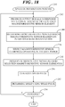
- FIG. 18 shows a flowchart of a speed determination process 240 in accordance with another embodiment.
- Speed determination process 240 summarizes the operations that may be executed within any of systems 100 ( FIG. 8 ), 132 ( FIG. 10 ), 180 ( FIG. 13 ), or another system having a greater quantity of magnetoresistive sensors.
- system 180 FIGs. 13 and 15
- encoder 102 coupled to shaft 108 is provided, in which encoder 102 is configured to produce external magnetic field 104 having predetermined magnetic variations (the presented alternating north (N) and south (S) pole configuration of encoder 102 yields the predetermined magnetic variations).
- External magnetic field 104 has a component, the Y-axis external magnetic field 110, that may be detectable by TMR sensor elements having the vortex magnetization pattern.
- output signals e.g., first, second, third, fourth, and fifth output signals 140, 142, 144, 188, 190
- output signals are produced in response to Y-axis external magnetic field 110 at each of a plurality of magnetoresistive sensor elements having a vortex magnetization pattern in the sense layer (e.g., first, second, third, fourth, and fifth TMR sensor elements 50A, 50B, 50C, 50D, 50E).
- a determination is made from the output signals as to which magnetoresistive sensor element(s) is/are operating in the safe range (e.g., safe range 172 of FIG. 12 ).
- magnetoresistive sensor elements are selected that are operating in the safe range and at a block 248 sensor output signals (e.g., sensor output signals 150 or 216) are produced from the selected magnetoresistive sensor element(s).
- sensor output signals e.g., sensor output signals 150 or 216
- a speed pulse may be generated at detected zero crossings as discussed above and at a block 252 the rotational speed is determined using the speed pulse. That is, the rotational speed of shaft 108 may be derived by counting the speed pulses per second.
- a determination is made as to whether process 240 should continue. For example, continued execution of speed determination process 240 may occur while shaft 108 continues to rotate and may be discontinued when shaft 108 is no longer rotating. When execution of speed determination process 240 is to continue, process control loops back to black 242. Otherwise, speed determination process 240 ends.
- Embodiments disclosed herein entail a magnetic field sensor, systems incorporating the magnetic field sensor, and methodology for measuring rotational speed of an object are disclosed herein.
- Each of the systems includes multiple magnetoresistive sensor elements, such as tunnel magnetoresistive (TMR) sensor elements, arranged in a gradient magnetic field sensing configuration.
- TMR tunnel magnetoresistive
- the sense layers (also referred to as free layers) of the TMR sensor elements are configured in a vortex state and are thus sensitive to in-plane magnetic fields along a single axis.
- Stability of the vortex state of the sensor elements may be achieved by a combination of measures including a multi-layered sense layer with a relatively thick soft magnetic material with high saturation magnetization and a relatively small diameter and thickness of the sense layer in which a compromise is achieved between manufacturability of the layer thickness and diameter. Further, stability of the vortex state may be achieved by an encoder magnet and sensor layout arrangement, a second-order gradient arrangement, and the ability to detect a critical situation and flag it to the user of the sensor.
Landscapes
- Physics & Mathematics (AREA)
- General Physics & Mathematics (AREA)
- Condensed Matter Physics & Semiconductors (AREA)
- Transmission And Conversion Of Sensor Element Output (AREA)
- Measuring Magnetic Variables (AREA)
Applications Claiming Priority (1)
| Application Number | Priority Date | Filing Date | Title |
|---|---|---|---|
| US16/388,167 US20200333407A1 (en) | 2019-04-18 | 2019-04-18 | Magnetic field sensor, system, and method for speed measurement |
Publications (2)
| Publication Number | Publication Date |
|---|---|
| EP3726237A2 true EP3726237A2 (de) | 2020-10-21 |
| EP3726237A3 EP3726237A3 (de) | 2020-11-04 |
Family
ID=70277233
Family Applications (1)
| Application Number | Title | Priority Date | Filing Date |
|---|---|---|---|
| EP20168792.8A Withdrawn EP3726237A3 (de) | 2019-04-18 | 2020-04-08 | Magnetfeldsensor, system und verfahren zur geschwindigkeitsmessung |
Country Status (3)
| Country | Link |
|---|---|
| US (1) | US20200333407A1 (de) |
| EP (1) | EP3726237A3 (de) |
| CN (1) | CN111830276A (de) |
Cited By (2)
| Publication number | Priority date | Publication date | Assignee | Title |
|---|---|---|---|---|
| EP4012431A1 (de) * | 2020-12-11 | 2022-06-15 | Crocus Technology S.A. | Magnetoresistives element zur erfassung eines magnetfeldes auf einer z-achse |
| WO2022195470A1 (en) * | 2021-03-19 | 2022-09-22 | Crocus Technology Sa | Magnetoresistive element and magnetic sensor device having a high sensitivity and low zero-field offset-shift |
Families Citing this family (8)
| Publication number | Priority date | Publication date | Assignee | Title |
|---|---|---|---|---|
| US12241865B2 (en) * | 2020-08-04 | 2025-03-04 | Brown University | Magnetic gradiometer based on magnetic tunnel junctions in magnetic vortex state (vortex MTJ) |
| US12442874B2 (en) * | 2021-11-04 | 2025-10-14 | Allegro Microsystems, Llc | Angle sensor with a single die using a single target |
| US12130342B2 (en) * | 2022-06-10 | 2024-10-29 | Allegro Microsystems, Llc | Magnetic field current sensor to reduce stray magnetic fields |
| US12181538B2 (en) | 2022-11-29 | 2024-12-31 | Allegro Microsystems, Llc | Magnetoresistance bridge circuits with stray field immunity |
| CN116106801B (zh) * | 2023-04-14 | 2023-06-20 | 珠海多创科技有限公司 | 磁阻传感器、磁传感装置及其制备方法 |
| CN116338537B (zh) * | 2023-04-14 | 2023-09-01 | 珠海多创科技有限公司 | 磁阻传感器及其制备方法、磁传感装置 |
| CN117794347B (zh) * | 2023-11-23 | 2024-05-31 | 珠海多创科技有限公司 | 磁阻元件、磁传感装置及其制备方法 |
| CN120693053A (zh) * | 2025-06-27 | 2025-09-23 | 珠海多创科技有限公司 | 一种磁阻元件、角度传感器及电子设备 |
Family Cites Families (17)
| Publication number | Priority date | Publication date | Assignee | Title |
|---|---|---|---|---|
| JP4202958B2 (ja) * | 2004-03-30 | 2008-12-24 | 株式会社東芝 | 磁気抵抗効果素子 |
| US7923987B2 (en) * | 2007-10-08 | 2011-04-12 | Infineon Technologies Ag | Magnetic sensor integrated circuit with test conductor |
| US8450996B2 (en) * | 2010-06-03 | 2013-05-28 | Allegro Microsystems, Llc | Motion sensor, method, and computer-readable storage medium providing a motion sensor with a magnetic field sensing element for generating a magnetic field signal and a state processor to identify a plurality of states corresponding to ranges of values of the magnetic field signal having a reduced amount of state chatter |
| US9671214B2 (en) * | 2013-07-17 | 2017-06-06 | Infineon Technologies Ag | Discrete magnetic angle sensor device, a magnetic angle sensor arrangement, a method for generating an angle signal and a method for providing a sensor signal |
| US10989769B2 (en) * | 2013-12-27 | 2021-04-27 | Infineon Technologies Ag | Magneto-resistive structured device having spontaneously generated in-plane closed flux magnetization pattern |
| US9562954B2 (en) * | 2014-08-06 | 2017-02-07 | Infineon Technologies Ag | Maximization of target signal and elimination of backbias component for a differential upright position sensor |
| EP3073274A1 (de) * | 2015-03-27 | 2016-09-28 | Alfa Laval Corporate AB | System zur detektion von rotation |
| FR3039269B1 (fr) * | 2015-07-21 | 2017-08-11 | Electricfil Automotive | Capteur de mesure de la position absolue d'un mobile |
| DE102016102214A1 (de) * | 2016-02-09 | 2017-08-10 | Infineon Technologies Ag | Magnetsensorbauelement und Verfahren für ein Magnetsensorbauelement mit einer magnetoresistiven Struktur |
| DE102016112008A1 (de) * | 2016-06-30 | 2018-01-04 | Infineon Technologies Ag | Magnetsensorbauelement und magneterfassungsverfahren |
| US10746572B2 (en) * | 2016-07-14 | 2020-08-18 | Denso Corporation | Rotation detection device |
| DE102017129346A1 (de) * | 2016-12-13 | 2018-06-14 | Infineon Technologies Ag | Magnetsensorschaltungen und -systeme und Verfahren zum Bilden von Magnetsensorschaltungen |
| DE102017112546B4 (de) * | 2017-06-07 | 2021-07-08 | Infineon Technologies Ag | Magnetoresistive Sensoren mit Magnetisierungsmustern mit geschlossenem Fluss |
| US10261138B2 (en) * | 2017-07-12 | 2019-04-16 | Nxp B.V. | Magnetic field sensor with magnetic field shield structure and systems incorporating same |
| US10509082B2 (en) * | 2018-02-08 | 2019-12-17 | Nxp B.V. | Magnetoresistive sensor systems with stray field cancellation utilizing auxiliary sensor signals |
| US10955493B2 (en) * | 2018-05-02 | 2021-03-23 | Analog Devices Global Unlimited Company | Magnetic sensor systems |
| US10802133B2 (en) * | 2018-05-17 | 2020-10-13 | Infineon Technologies Ag | Diverse sensing using different types of sensors |
-
2019
- 2019-04-18 US US16/388,167 patent/US20200333407A1/en not_active Abandoned
-
2020
- 2020-04-08 EP EP20168792.8A patent/EP3726237A3/de not_active Withdrawn
- 2020-04-14 CN CN202010293008.7A patent/CN111830276A/zh active Pending
Cited By (5)
| Publication number | Priority date | Publication date | Assignee | Title |
|---|---|---|---|---|
| EP4012431A1 (de) * | 2020-12-11 | 2022-06-15 | Crocus Technology S.A. | Magnetoresistives element zur erfassung eines magnetfeldes auf einer z-achse |
| WO2022123472A1 (en) * | 2020-12-11 | 2022-06-16 | Crocus Technology Sa | Magnetoresistive element for sensing a magnetic field in a z-axis |
| US12320873B2 (en) | 2020-12-11 | 2025-06-03 | Allegro Microsystems, Llc | Magnetoresistive element for sensing a magnetic field in a Z-axis |
| WO2022195470A1 (en) * | 2021-03-19 | 2022-09-22 | Crocus Technology Sa | Magnetoresistive element and magnetic sensor device having a high sensitivity and low zero-field offset-shift |
| US12360183B2 (en) | 2021-03-19 | 2025-07-15 | Allegro Microsystems, Llc | Magnetoresistive element and magnetic sensor device having a high sensitivity and low zero-field offset-shift |
Also Published As
| Publication number | Publication date |
|---|---|
| EP3726237A3 (de) | 2020-11-04 |
| US20200333407A1 (en) | 2020-10-22 |
| CN111830276A (zh) | 2020-10-27 |
Similar Documents
| Publication | Publication Date | Title |
|---|---|---|
| EP3726237A2 (de) | Magnetfeldsensor, system und verfahren zur geschwindigkeitsmessung | |
| TWI719574B (zh) | 磁阻元件、磁阻結構及三維磁場感測器 | |
| EP2801834B1 (de) | Stromsensor | |
| CN109959396B (zh) | 多圈计数器传感器 | |
| JP5552029B2 (ja) | 位置測定用の磁気エンコーダー素子 | |
| US11022661B2 (en) | Magnetoresistance element with increased operational range | |
| US10989769B2 (en) | Magneto-resistive structured device having spontaneously generated in-plane closed flux magnetization pattern | |
| JP6193212B2 (ja) | シングルチップ2軸ブリッジ型磁界センサ | |
| CN202083786U (zh) | 薄膜磁电阻传感元件、多个传感元件的组合及与该组合耦合的电子装置 | |
| EP3764115B1 (de) | Magnetfeldsensor mit magnetoresistiven elementen, die in einer brücke angeordnet sind und eine gemeinsame referenzrichtung und entgegengesetzte vorspannrichtungen aufweisen | |
| JP6202282B2 (ja) | 磁気センサ | |
| US12130342B2 (en) | Magnetic field current sensor to reduce stray magnetic fields | |
| US20140139214A1 (en) | Magnetic sensor using spin transfer torque devices | |
| CN102435963A (zh) | 单片双轴桥式磁场传感器 | |
| CN117794347B (zh) | 磁阻元件、磁传感装置及其制备方法 | |
| TWI518330B (zh) | 慣性感應器 | |
| JP2022158932A (ja) | 磁気センサ装置 | |
| US10852365B2 (en) | Stray field suppression in magnetic sensor Wheatstone bridges | |
| JP6969751B2 (ja) | トンネル磁気抵抗素子及び磁化方向補正回路 | |
| EP3779491A1 (de) | Magnetfeldsensor und herstellungsverfahren für schräg einfallende abscheidung | |
| CN118501783A (zh) | 一种磁阻元件、磁开关传感器及电子设备 | |
| JP2015212628A (ja) | 磁気センサの使用方法及び磁気センサのバイアス磁場の決定方法 | |
| CN117388768B (zh) | 磁阻元件及其制备方法、磁阻传感器 | |
| US20260104478A1 (en) | Tmr sensor having antiferromagnetically coupled vortices | |
| JP2017191112A (ja) | 慣性センサ |
Legal Events
| Date | Code | Title | Description |
|---|---|---|---|
| PUAI | Public reference made under article 153(3) epc to a published international application that has entered the european phase |
Free format text: ORIGINAL CODE: 0009012 |
|
| STAA | Information on the status of an ep patent application or granted ep patent |
Free format text: STATUS: THE APPLICATION HAS BEEN PUBLISHED |
|
| PUAL | Search report despatched |
Free format text: ORIGINAL CODE: 0009013 |
|
| AK | Designated contracting states |
Kind code of ref document: A2 Designated state(s): AL AT BE BG CH CY CZ DE DK EE ES FI FR GB GR HR HU IE IS IT LI LT LU LV MC MK MT NL NO PL PT RO RS SE SI SK SM TR |
|
| AX | Request for extension of the european patent |
Extension state: BA ME |
|
| AK | Designated contracting states |
Kind code of ref document: A3 Designated state(s): AL AT BE BG CH CY CZ DE DK EE ES FI FR GB GR HR HU IE IS IT LI LT LU LV MC MK MT NL NO PL PT RO RS SE SI SK SM TR |
|
| AX | Request for extension of the european patent |
Extension state: BA ME |
|
| RIC1 | Information provided on ipc code assigned before grant |
Ipc: G01R 33/09 20060101ALI20200928BHEP Ipc: G01R 33/00 20060101AFI20200928BHEP Ipc: G01R 33/022 20060101ALI20200928BHEP |
|
| STAA | Information on the status of an ep patent application or granted ep patent |
Free format text: STATUS: REQUEST FOR EXAMINATION WAS MADE |
|
| 17P | Request for examination filed |
Effective date: 20210504 |
|
| RBV | Designated contracting states (corrected) |
Designated state(s): AL AT BE BG CH CY CZ DE DK EE ES FI FR GB GR HR HU IE IS IT LI LT LU LV MC MK MT NL NO PL PT RO RS SE SI SK SM TR |
|
| STAA | Information on the status of an ep patent application or granted ep patent |
Free format text: STATUS: THE APPLICATION IS DEEMED TO BE WITHDRAWN |
|
| 18D | Application deemed to be withdrawn |
Effective date: 20210505 |