EP3726546A1 - Soupape à solénoïde à double bobine pour une soupape de commande de gaz combustible et son procédé de commande - Google Patents
Soupape à solénoïde à double bobine pour une soupape de commande de gaz combustible et son procédé de commande Download PDFInfo
- Publication number
- EP3726546A1 EP3726546A1 EP19191833.3A EP19191833A EP3726546A1 EP 3726546 A1 EP3726546 A1 EP 3726546A1 EP 19191833 A EP19191833 A EP 19191833A EP 3726546 A1 EP3726546 A1 EP 3726546A1
- Authority
- EP
- European Patent Office
- Prior art keywords
- coil
- coil assembly
- stationary
- moving
- current
- Prior art date
- Legal status (The legal status is an assumption and is not a legal conclusion. Google has not performed a legal analysis and makes no representation as to the accuracy of the status listed.)
- Granted
Links
Images

Classifications
-
- H—ELECTRICITY
- H01—ELECTRIC ELEMENTS
- H01F—MAGNETS; INDUCTANCES; TRANSFORMERS; SELECTION OF MATERIALS FOR THEIR MAGNETIC PROPERTIES
- H01F7/00—Magnets
- H01F7/06—Electromagnets; Actuators including electromagnets
- H01F7/066—Electromagnets with movable winding
-
- F—MECHANICAL ENGINEERING; LIGHTING; HEATING; WEAPONS; BLASTING
- F16—ENGINEERING ELEMENTS AND UNITS; GENERAL MEASURES FOR PRODUCING AND MAINTAINING EFFECTIVE FUNCTIONING OF MACHINES OR INSTALLATIONS; THERMAL INSULATION IN GENERAL
- F16K—VALVES; TAPS; COCKS; ACTUATING-FLOATS; DEVICES FOR VENTING OR AERATING
- F16K31/00—Actuating devices; Operating means; Releasing devices
- F16K31/02—Actuating devices; Operating means; Releasing devices electric; magnetic
- F16K31/06—Actuating devices; Operating means; Releasing devices electric; magnetic using a magnet, e.g. diaphragm valves, cutting off by means of a liquid
- F16K31/0675—Electromagnet aspects, e.g. electric supply therefor
- F16K31/0679—Electromagnet aspects, e.g. electric supply therefor with more than one energising coil
-
- F—MECHANICAL ENGINEERING; LIGHTING; HEATING; WEAPONS; BLASTING
- F16—ENGINEERING ELEMENTS AND UNITS; GENERAL MEASURES FOR PRODUCING AND MAINTAINING EFFECTIVE FUNCTIONING OF MACHINES OR INSTALLATIONS; THERMAL INSULATION IN GENERAL
- F16K—VALVES; TAPS; COCKS; ACTUATING-FLOATS; DEVICES FOR VENTING OR AERATING
- F16K31/00—Actuating devices; Operating means; Releasing devices
- F16K31/02—Actuating devices; Operating means; Releasing devices electric; magnetic
- F16K31/06—Actuating devices; Operating means; Releasing devices electric; magnetic using a magnet, e.g. diaphragm valves, cutting off by means of a liquid
- F16K31/0644—One-way valve
- F16K31/0655—Lift valves
-
- H—ELECTRICITY
- H01—ELECTRIC ELEMENTS
- H01F—MAGNETS; INDUCTANCES; TRANSFORMERS; SELECTION OF MATERIALS FOR THEIR MAGNETIC PROPERTIES
- H01F7/00—Magnets
- H01F7/06—Electromagnets; Actuators including electromagnets
- H01F7/08—Electromagnets; Actuators including electromagnets with armatures
- H01F7/18—Circuit arrangements for obtaining desired operating characteristics, e.g. for slow operation, for sequential energisation of windings, for high-speed energisation of windings
- H01F7/1805—Circuit arrangements for holding the operation of electromagnets or for holding the armature in attracted position with reduced energising current
-
- H—ELECTRICITY
- H01—ELECTRIC ELEMENTS
- H01F—MAGNETS; INDUCTANCES; TRANSFORMERS; SELECTION OF MATERIALS FOR THEIR MAGNETIC PROPERTIES
- H01F7/00—Magnets
- H01F7/06—Electromagnets; Actuators including electromagnets
- H01F7/08—Electromagnets; Actuators including electromagnets with armatures
- H01F7/081—Magnetic constructions
- H01F2007/086—Structural details of the armature
-
- H—ELECTRICITY
- H01—ELECTRIC ELEMENTS
- H01F—MAGNETS; INDUCTANCES; TRANSFORMERS; SELECTION OF MATERIALS FOR THEIR MAGNETIC PROPERTIES
- H01F7/00—Magnets
- H01F7/06—Electromagnets; Actuators including electromagnets
- H01F7/08—Electromagnets; Actuators including electromagnets with armatures
- H01F7/16—Rectilinearly-movable armatures
- H01F2007/1692—Electromagnets or actuators with two coils
-
- H—ELECTRICITY
- H01—ELECTRIC ELEMENTS
- H01F—MAGNETS; INDUCTANCES; TRANSFORMERS; SELECTION OF MATERIALS FOR THEIR MAGNETIC PROPERTIES
- H01F6/00—Superconducting magnets; Superconducting coils
Definitions
- the present invention relates to a solenoid valve, and in particular to a dual coil solenoid valve for a fuel gas control valve and a control method thereof.
- An electromagnet is an electrical device which attracts a ferromagnetic substance and converts an electromagnetic energy into a mechanical energy after being electrified.
- an electromagnet is used in a fuel gas control valve to form a solenoid valve, the opening and closing of the fuel gas valve can be realized by turning on and turning off the power of the solenoid valve, and the functions such as alarm and protection can also be realized.
- electromagnets There are many types of electromagnets. However, they have the same basic composition and operational principle and usually consist of three major parts: coil, iron core and armature iron.
- the coil contains the iron core and, after being electrified, it generates magnetic forces to attract the armature iron.
- the material of the iron core is usually soft iron or silicon steel.
- the solenoid valve of the prior art require a certain number of ampere-turns to produce a large enough attraction force, while owning to the size limitation, it is impossible to make a very large fuel gas control valve; therefore, the solenoid valve can work only when a large current is applied to the coils, and as a result, energy is consumed very quickly, and as the consumed energy is converted into heat energy, the magnet coils easily get hot after they work for a long time, which in turn accelerates the aging of related components on the solenoid valve or even damages them.
- the solenoid valve when used in a specific environment, for example, in an outdoor environment, where the mains power supply is unavailable or inconvenient and a battery needs to be used as a power supply, the limited energy stored in the battery cannot last long due to the large energy consumption, so the fuel gas control valve has application limitations.
- the technical problem to be solved by the present invention is to provide a dual coil solenoid valve for a fuel gas control valve, and the present invention can provide a very small current to the coils of the solenoid valve to maintain the attracted contact state of the solenoid valve, that is, the open state of the fuel gas control valve.
- a dual coil solenoid valve for a fuel gas control valve said dual coil solenoid valve comprising a stationary coil assembly and a moving coil assembly.
- Said stationary coil assembly comprises a stationary magnetic core and a stationary coil
- said moving coil assembly comprises a moving magnetic core and a moving coil
- said stationary coil assembly and said moving coil assembly have the same cross-sectional shape and area and are arranged oppositely with their axes coinciding with each other
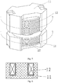
- said stationary magnetic core and moving magnetic core are E-shaped, that is, grooves are formed in said stationary magnetic core and moving magnetic core
- said stationary coil and moving coil are arranged in said grooves.
- the coils on said stationary coil assembly and moving coil assembly are wound in the same direction according to their installation positions in said dual coil solenoid valve, that is, the direction of magnetism produced from said stationary magnetic core after said stationary coil is electrified is the same as the direction of magnetism produced from said moving magnetic core after said moving coil is electrified, and the magnetic poles produced by the matching sides between said stationary coil assembly and said moving coil assembly are opposite such that, according to the rule of opposite magnetic poles attracting each other, the magnetic forces produced by said stationary coil assembly and said moving coil assembly are superposed after said stationary coil assembly and said moving coil assembly are electrified.
- the material of said stationary magnetic core and said moving magnetic core is manganese-zinc ferrite with a high magnetic conductivity or a superconducting material.
- said attracting current is 4-50 times the maintaining current
- said maintaining current is 2 mA ⁇ 200 mA.
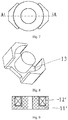
- said stationary magnetic core and moving magnetic core can also be in the shape of a round jug and the grooves formed in said stationary magnetic core and moving magnetic core are annular grooves.
- guide poles are arranged between said stationary coil assembly and said moving coil assembly so that the moving coil assembly can move along a straight line.
- a push rod is arranged on said moving coil assembly, one end of said push rod is fixed onto said moving coil assembly, the other end is provided with a sealing cushion, and a spring is arranged between said sealing cushion and said moving coil assembly.
- a control method of the dual coil solenoid valve for a fuel gas control valve comprises the following steps:
- the present invention provides a dual coil solenoid valve for a fuel gas control valve, wherein a current is simultaneously applied to the two coils, said magnetic cores are inside said coils, and said magnetic cores also surround said coils so that the magnetic flux in said magnetic cores is increased, and a large attraction force can be generated only by applying a small current, which results in a solenoid valve that has a low power consumption, a small size and a simple structure and is applicable to most fuel gas control valves.
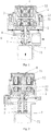
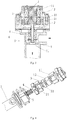
- a dual coil solenoid valve for s fuel gas control valve comprises a stationary coil assembly 1 and a moving coil assembly 2, said stationary coil assembly 1 comprises a stationary magnetic core 11 and a stationary coil 12, said moving coil assembly 2 comprises a moving magnetic core 21 and a moving coil 22, the materials of said stationary magnetic core 11 and moving magnetic core 21 are both a manganese-zinc ferrite with a high magnetic conductivity, said stationary magnetic core 11 and moving magnetic core 21 are both E-shaped, that is, a notched groove 13 is formed in said stationary magnetic core 11 and said moving magnetic core 21, said stationary coil 12 and moving coil 22 are respectively arranged in the grooves 13 in said stationary magnetic core 11 and moving magnetic core 21, the coils on said stationary coil assembly 1 and moving coil assembly 2 are wound in the same direction according to their installation positions in said dual coil solenoid valve, said stationary coil assembly 1 and said moving coil assembly 2 have the same cross-sectional shape and area and are arranged oppositely with their axes coinciding with each other, guide pole
- the magnetic forces produced by said stationary coil assembly 1 and said moving coil assembly 2 are superposed to drive the moving coil assembly 2 to move along the guide poles and come into contact with the stationary coil assembly 1 after said stationary coil assembly 1 and said moving coil assembly 2 are electrified.
- the moving coil assembly 2 drives the push rod 4 and the sealing cushion 5 to compress the spring 6 to separate the sealing cushion from the gas port 71, and thus the fuel gas control valve is opened.
- the current in the stationary coil 11 and moving coil 21 is reduced, and only a small maintaining current is needed to maintain the contact state, that is, keep the fuel gas control valve always in the open state.
- the fuel gas control valve needs to be closed, only the power supply to the stationary coil 11 and the moving coil 21 needs to be cut off.
- the attracting current is 4-50 times the maintaining current and said maintaining current is 2 mA ⁇ 200 mA.
- the magnetic core coil of the dual coil solenoid valve for a fuel gas control valve has another structure, wherein said magnetic core is a jug-shaped magnetic core 11', an annular groove 13' is provided in the jug-shaped magnetic core, and said jug-shaped magnetic core coil 12' is arranged in said annular groove 13'.
Landscapes
- Physics & Mathematics (AREA)
- Electromagnetism (AREA)
- Engineering & Computer Science (AREA)
- General Engineering & Computer Science (AREA)
- Mechanical Engineering (AREA)
- Power Engineering (AREA)
- Magnetically Actuated Valves (AREA)
Priority Applications (1)
| Application Number | Priority Date | Filing Date | Title |
|---|---|---|---|
| PL19191833T PL3726546T3 (pl) | 2019-04-17 | 2019-08-14 | Zawór elektromagnetyczny z podwójną cewką dla zaworu sterującego paliwa gazowego i jego sposób sterowania |
Applications Claiming Priority (2)
| Application Number | Priority Date | Filing Date | Title |
|---|---|---|---|
| CN201920515866.4U CN209990987U (zh) | 2019-04-17 | 2019-04-17 | 一种用于燃气控制阀的双线圈电磁阀 |
| CN201910306166.9A CN110735961A (zh) | 2019-04-17 | 2019-04-17 | 一种用于燃气控制阀的双线圈电磁阀及控制方法 |
Publications (2)
| Publication Number | Publication Date |
|---|---|
| EP3726546A1 true EP3726546A1 (fr) | 2020-10-21 |
| EP3726546B1 EP3726546B1 (fr) | 2021-07-14 |
Family
ID=67658941
Family Applications (1)
| Application Number | Title | Priority Date | Filing Date |
|---|---|---|---|
| EP19191833.3A Active EP3726546B1 (fr) | 2019-04-17 | 2019-08-14 | Soupape à solénoïde à double bobine pour une soupape de commande de gaz combustible et son procédé de commande |
Country Status (4)
| Country | Link |
|---|---|
| US (1) | US11047500B2 (fr) |
| EP (1) | EP3726546B1 (fr) |
| ES (1) | ES2887284T3 (fr) |
| PL (1) | PL3726546T3 (fr) |
Families Citing this family (2)
| Publication number | Priority date | Publication date | Assignee | Title |
|---|---|---|---|---|
| CN113236845A (zh) * | 2021-03-23 | 2021-08-10 | 华帝股份有限公司 | 一种用于燃气灶的电磁阀及其控制方法 |
| KR102585781B1 (ko) * | 2021-09-08 | 2023-10-05 | 주식회사 현대케피코 | 차량의 연료탱크 차단밸브 |
Citations (4)
| Publication number | Priority date | Publication date | Assignee | Title |
|---|---|---|---|---|
| DE3611221A1 (de) * | 1985-04-25 | 1986-11-06 | Klöckner, Wolfgang, Dr., 8033 Krailling | Brennkraftmaschine mit gaswechselventilen |
| US20010029905A1 (en) * | 2000-04-17 | 2001-10-18 | Paloma Industries, Limited | Water heater with a flame arrester |
| US20110094589A1 (en) * | 2009-10-28 | 2011-04-28 | Jacob Steven D | Method of controlling solenoid valve |
| WO2014187195A1 (fr) * | 2013-05-24 | 2014-11-27 | 广州微点焊设备有限公司 | Appareil de puissance électromagnétique de suspension |
Family Cites Families (3)
| Publication number | Priority date | Publication date | Assignee | Title |
|---|---|---|---|---|
| US618702A (en) * | 1899-01-31 | James it | ||
| JP3142038B2 (ja) * | 1993-12-03 | 2001-03-07 | 株式会社デンソー | 電磁弁 |
| EP1447824B8 (fr) * | 2001-10-29 | 2015-10-28 | Sumitomo Electric Sintered Alloy, Ltd. | Procede de production d'un materiau magnetique composite |
-
2019
- 2019-08-14 EP EP19191833.3A patent/EP3726546B1/fr active Active
- 2019-08-14 ES ES19191833T patent/ES2887284T3/es active Active
- 2019-08-14 PL PL19191833T patent/PL3726546T3/pl unknown
- 2019-08-30 US US16/557,021 patent/US11047500B2/en active Active
Patent Citations (4)
| Publication number | Priority date | Publication date | Assignee | Title |
|---|---|---|---|---|
| DE3611221A1 (de) * | 1985-04-25 | 1986-11-06 | Klöckner, Wolfgang, Dr., 8033 Krailling | Brennkraftmaschine mit gaswechselventilen |
| US20010029905A1 (en) * | 2000-04-17 | 2001-10-18 | Paloma Industries, Limited | Water heater with a flame arrester |
| US20110094589A1 (en) * | 2009-10-28 | 2011-04-28 | Jacob Steven D | Method of controlling solenoid valve |
| WO2014187195A1 (fr) * | 2013-05-24 | 2014-11-27 | 广州微点焊设备有限公司 | Appareil de puissance électromagnétique de suspension |
Also Published As
| Publication number | Publication date |
|---|---|
| US11047500B2 (en) | 2021-06-29 |
| PL3726546T3 (pl) | 2022-06-27 |
| US20200332915A1 (en) | 2020-10-22 |
| ES2887284T3 (es) | 2021-12-22 |
| EP3726546B1 (fr) | 2021-07-14 |
Similar Documents
| Publication | Publication Date | Title |
|---|---|---|
| US3814376A (en) | Solenoid operated valve with magnetic latch | |
| US8461951B2 (en) | Bistable magnetic actuators | |
| JPH0134326Y2 (fr) | ||
| US3379214A (en) | Permanent magnet valve assembly | |
| US4538129A (en) | Magnetic flux-shifting actuator | |
| US4306207A (en) | Self-sustaining solenoid | |
| EP1509716B1 (fr) | Actionneur electromagnetique pivotant, actionneur integre et vanne de regulation d'ecoulement de fluide | |
| CN108916454B (zh) | 大行程衔铁密封型节能电磁阀 | |
| CN106895194B (zh) | 小型高压自锁阀 | |
| EP3726546A1 (fr) | Soupape à solénoïde à double bobine pour une soupape de commande de gaz combustible et son procédé de commande | |
| US3120943A (en) | Impulse solenoid actuated pivoted valve | |
| US5239277A (en) | Electromagnetic solenoid actuator | |
| CN206619458U (zh) | 一种轴向磁化永磁电磁铁 | |
| CN212691001U (zh) | 一种稳态脉冲电磁阀 | |
| CN206268570U (zh) | 一种电磁阀用双向定位式永磁操作机构 | |
| CN209990987U (zh) | 一种用于燃气控制阀的双线圈电磁阀 | |
| JPH0236043B2 (fr) | ||
| RU2313716C2 (ru) | Электромагнитный клапан | |
| CN110735961A (zh) | 一种用于燃气控制阀的双线圈电磁阀及控制方法 | |
| JPH11210430A (ja) | エンジンバルブ駆動用アクチュエータ | |
| JP3251085B2 (ja) | 電磁弁 | |
| GB853396A (en) | Improvements in electromagnetic fluid control valves | |
| JP2000161523A (ja) | 液圧媒体用電磁弁 | |
| KR20150144131A (ko) | 저전력 솔레노이드 구조 및 이의 제어 방법 | |
| JPS6334245Y2 (fr) |
Legal Events
| Date | Code | Title | Description |
|---|---|---|---|
| PUAI | Public reference made under article 153(3) epc to a published international application that has entered the european phase |
Free format text: ORIGINAL CODE: 0009012 |
|
| STAA | Information on the status of an ep patent application or granted ep patent |
Free format text: STATUS: THE APPLICATION HAS BEEN PUBLISHED |
|
| AK | Designated contracting states |
Kind code of ref document: A1 Designated state(s): AL AT BE BG CH CY CZ DE DK EE ES FI FR GB GR HR HU IE IS IT LI LT LU LV MC MK MT NL NO PL PT RO RS SE SI SK SM TR |
|
| AX | Request for extension of the european patent |
Extension state: BA ME |
|
| STAA | Information on the status of an ep patent application or granted ep patent |
Free format text: STATUS: REQUEST FOR EXAMINATION WAS MADE |
|
| 17P | Request for examination filed |
Effective date: 20201111 |
|
| RBV | Designated contracting states (corrected) |
Designated state(s): AL AT BE BG CH CY CZ DE DK EE ES FI FR GB GR HR HU IE IS IT LI LT LU LV MC MK MT NL NO PL PT RO RS SE SI SK SM TR |
|
| GRAP | Despatch of communication of intention to grant a patent |
Free format text: ORIGINAL CODE: EPIDOSNIGR1 |
|
| STAA | Information on the status of an ep patent application or granted ep patent |
Free format text: STATUS: GRANT OF PATENT IS INTENDED |
|
| INTG | Intention to grant announced |
Effective date: 20210426 |
|
| GRAS | Grant fee paid |
Free format text: ORIGINAL CODE: EPIDOSNIGR3 |
|
| GRAA | (expected) grant |
Free format text: ORIGINAL CODE: 0009210 |
|
| STAA | Information on the status of an ep patent application or granted ep patent |
Free format text: STATUS: THE PATENT HAS BEEN GRANTED |
|
| AK | Designated contracting states |
Kind code of ref document: B1 Designated state(s): AL AT BE BG CH CY CZ DE DK EE ES FI FR GB GR HR HU IE IS IT LI LT LU LV MC MK MT NL NO PL PT RO RS SE SI SK SM TR |
|
| REG | Reference to a national code |
Ref country code: GB Ref legal event code: FG4D |
|
| REG | Reference to a national code |
Ref country code: DE Ref legal event code: R096 Ref document number: 602019006072 Country of ref document: DE |
|
| REG | Reference to a national code |
Ref country code: IE Ref legal event code: FG4D |
|
| REG | Reference to a national code |
Ref country code: AT Ref legal event code: REF Ref document number: 1411302 Country of ref document: AT Kind code of ref document: T Effective date: 20210815 |
|
| REG | Reference to a national code |
Ref country code: NL Ref legal event code: FP |
|
| REG | Reference to a national code |
Ref country code: LT Ref legal event code: MG9D |
|
| REG | Reference to a national code |
Ref country code: AT Ref legal event code: MK05 Ref document number: 1411302 Country of ref document: AT Kind code of ref document: T Effective date: 20210714 |
|
| REG | Reference to a national code |
Ref country code: ES Ref legal event code: FG2A Ref document number: 2887284 Country of ref document: ES Kind code of ref document: T3 Effective date: 20211222 |
|
| PG25 | Lapsed in a contracting state [announced via postgrant information from national office to epo] |
Ref country code: FI Free format text: LAPSE BECAUSE OF FAILURE TO SUBMIT A TRANSLATION OF THE DESCRIPTION OR TO PAY THE FEE WITHIN THE PRESCRIBED TIME-LIMIT Effective date: 20210714 Ref country code: RS Free format text: LAPSE BECAUSE OF FAILURE TO SUBMIT A TRANSLATION OF THE DESCRIPTION OR TO PAY THE FEE WITHIN THE PRESCRIBED TIME-LIMIT Effective date: 20210714 Ref country code: SE Free format text: LAPSE BECAUSE OF FAILURE TO SUBMIT A TRANSLATION OF THE DESCRIPTION OR TO PAY THE FEE WITHIN THE PRESCRIBED TIME-LIMIT Effective date: 20210714 Ref country code: NO Free format text: LAPSE BECAUSE OF FAILURE TO SUBMIT A TRANSLATION OF THE DESCRIPTION OR TO PAY THE FEE WITHIN THE PRESCRIBED TIME-LIMIT Effective date: 20211014 Ref country code: PT Free format text: LAPSE BECAUSE OF FAILURE TO SUBMIT A TRANSLATION OF THE DESCRIPTION OR TO PAY THE FEE WITHIN THE PRESCRIBED TIME-LIMIT Effective date: 20211115 Ref country code: HR Free format text: LAPSE BECAUSE OF FAILURE TO SUBMIT A TRANSLATION OF THE DESCRIPTION OR TO PAY THE FEE WITHIN THE PRESCRIBED TIME-LIMIT Effective date: 20210714 Ref country code: AT Free format text: LAPSE BECAUSE OF FAILURE TO SUBMIT A TRANSLATION OF THE DESCRIPTION OR TO PAY THE FEE WITHIN THE PRESCRIBED TIME-LIMIT Effective date: 20210714 Ref country code: BG Free format text: LAPSE BECAUSE OF FAILURE TO SUBMIT A TRANSLATION OF THE DESCRIPTION OR TO PAY THE FEE WITHIN THE PRESCRIBED TIME-LIMIT Effective date: 20211014 Ref country code: LT Free format text: LAPSE BECAUSE OF FAILURE TO SUBMIT A TRANSLATION OF THE DESCRIPTION OR TO PAY THE FEE WITHIN THE PRESCRIBED TIME-LIMIT Effective date: 20210714 |
|
| PG25 | Lapsed in a contracting state [announced via postgrant information from national office to epo] |
Ref country code: LV Free format text: LAPSE BECAUSE OF FAILURE TO SUBMIT A TRANSLATION OF THE DESCRIPTION OR TO PAY THE FEE WITHIN THE PRESCRIBED TIME-LIMIT Effective date: 20210714 Ref country code: GR Free format text: LAPSE BECAUSE OF FAILURE TO SUBMIT A TRANSLATION OF THE DESCRIPTION OR TO PAY THE FEE WITHIN THE PRESCRIBED TIME-LIMIT Effective date: 20211015 |
|
| REG | Reference to a national code |
Ref country code: DE Ref legal event code: R097 Ref document number: 602019006072 Country of ref document: DE |
|
| REG | Reference to a national code |
Ref country code: BE Ref legal event code: MM Effective date: 20210831 |
|
| PG25 | Lapsed in a contracting state [announced via postgrant information from national office to epo] |
Ref country code: DK Free format text: LAPSE BECAUSE OF FAILURE TO SUBMIT A TRANSLATION OF THE DESCRIPTION OR TO PAY THE FEE WITHIN THE PRESCRIBED TIME-LIMIT Effective date: 20210714 |
|
| PLBE | No opposition filed within time limit |
Free format text: ORIGINAL CODE: 0009261 |
|
| STAA | Information on the status of an ep patent application or granted ep patent |
Free format text: STATUS: NO OPPOSITION FILED WITHIN TIME LIMIT |
|
| PG25 | Lapsed in a contracting state [announced via postgrant information from national office to epo] |
Ref country code: SM Free format text: LAPSE BECAUSE OF FAILURE TO SUBMIT A TRANSLATION OF THE DESCRIPTION OR TO PAY THE FEE WITHIN THE PRESCRIBED TIME-LIMIT Effective date: 20210714 Ref country code: SK Free format text: LAPSE BECAUSE OF FAILURE TO SUBMIT A TRANSLATION OF THE DESCRIPTION OR TO PAY THE FEE WITHIN THE PRESCRIBED TIME-LIMIT Effective date: 20210714 Ref country code: RO Free format text: LAPSE BECAUSE OF FAILURE TO SUBMIT A TRANSLATION OF THE DESCRIPTION OR TO PAY THE FEE WITHIN THE PRESCRIBED TIME-LIMIT Effective date: 20210714 Ref country code: MC Free format text: LAPSE BECAUSE OF FAILURE TO SUBMIT A TRANSLATION OF THE DESCRIPTION OR TO PAY THE FEE WITHIN THE PRESCRIBED TIME-LIMIT Effective date: 20210714 Ref country code: LU Free format text: LAPSE BECAUSE OF NON-PAYMENT OF DUE FEES Effective date: 20210814 Ref country code: EE Free format text: LAPSE BECAUSE OF FAILURE TO SUBMIT A TRANSLATION OF THE DESCRIPTION OR TO PAY THE FEE WITHIN THE PRESCRIBED TIME-LIMIT Effective date: 20210714 Ref country code: CZ Free format text: LAPSE BECAUSE OF FAILURE TO SUBMIT A TRANSLATION OF THE DESCRIPTION OR TO PAY THE FEE WITHIN THE PRESCRIBED TIME-LIMIT Effective date: 20210714 Ref country code: AL Free format text: LAPSE BECAUSE OF FAILURE TO SUBMIT A TRANSLATION OF THE DESCRIPTION OR TO PAY THE FEE WITHIN THE PRESCRIBED TIME-LIMIT Effective date: 20210714 |
|
| 26N | No opposition filed |
Effective date: 20220419 |
|
| PG25 | Lapsed in a contracting state [announced via postgrant information from national office to epo] |
Ref country code: IE Free format text: LAPSE BECAUSE OF NON-PAYMENT OF DUE FEES Effective date: 20210814 Ref country code: BE Free format text: LAPSE BECAUSE OF NON-PAYMENT OF DUE FEES Effective date: 20210831 |
|
| REG | Reference to a national code |
Ref country code: CH Ref legal event code: PL |
|
| PG25 | Lapsed in a contracting state [announced via postgrant information from national office to epo] |
Ref country code: LI Free format text: LAPSE BECAUSE OF NON-PAYMENT OF DUE FEES Effective date: 20220831 Ref country code: CH Free format text: LAPSE BECAUSE OF NON-PAYMENT OF DUE FEES Effective date: 20220831 |
|
| PG25 | Lapsed in a contracting state [announced via postgrant information from national office to epo] |
Ref country code: CY Free format text: LAPSE BECAUSE OF FAILURE TO SUBMIT A TRANSLATION OF THE DESCRIPTION OR TO PAY THE FEE WITHIN THE PRESCRIBED TIME-LIMIT Effective date: 20210714 |
|
| PG25 | Lapsed in a contracting state [announced via postgrant information from national office to epo] |
Ref country code: HU Free format text: LAPSE BECAUSE OF FAILURE TO SUBMIT A TRANSLATION OF THE DESCRIPTION OR TO PAY THE FEE WITHIN THE PRESCRIBED TIME-LIMIT; INVALID AB INITIO Effective date: 20190814 |
|
| PG25 | Lapsed in a contracting state [announced via postgrant information from national office to epo] |
Ref country code: MK Free format text: LAPSE BECAUSE OF FAILURE TO SUBMIT A TRANSLATION OF THE DESCRIPTION OR TO PAY THE FEE WITHIN THE PRESCRIBED TIME-LIMIT Effective date: 20210714 |
|
| PG25 | Lapsed in a contracting state [announced via postgrant information from national office to epo] |
Ref country code: TR Free format text: LAPSE BECAUSE OF FAILURE TO SUBMIT A TRANSLATION OF THE DESCRIPTION OR TO PAY THE FEE WITHIN THE PRESCRIBED TIME-LIMIT Effective date: 20210714 |
|
| PG25 | Lapsed in a contracting state [announced via postgrant information from national office to epo] |
Ref country code: MT Free format text: LAPSE BECAUSE OF FAILURE TO SUBMIT A TRANSLATION OF THE DESCRIPTION OR TO PAY THE FEE WITHIN THE PRESCRIBED TIME-LIMIT Effective date: 20210714 |
|
| PGFP | Annual fee paid to national office [announced via postgrant information from national office to epo] |
Ref country code: NL Payment date: 20250821 Year of fee payment: 7 |
|
| PGFP | Annual fee paid to national office [announced via postgrant information from national office to epo] |
Ref country code: ES Payment date: 20250926 Year of fee payment: 7 |
|
| PGFP | Annual fee paid to national office [announced via postgrant information from national office to epo] |
Ref country code: DE Payment date: 20250820 Year of fee payment: 7 |
|
| PGFP | Annual fee paid to national office [announced via postgrant information from national office to epo] |
Ref country code: PL Payment date: 20250814 Year of fee payment: 7 Ref country code: IT Payment date: 20250825 Year of fee payment: 7 |
|
| PGFP | Annual fee paid to national office [announced via postgrant information from national office to epo] |
Ref country code: GB Payment date: 20250820 Year of fee payment: 7 |
|
| PGFP | Annual fee paid to national office [announced via postgrant information from national office to epo] |
Ref country code: FR Payment date: 20250828 Year of fee payment: 7 |