EP3726560A1 - Disjoncteur de protection compact - Google Patents
Disjoncteur de protection compact Download PDFInfo
- Publication number
- EP3726560A1 EP3726560A1 EP20167008.0A EP20167008A EP3726560A1 EP 3726560 A1 EP3726560 A1 EP 3726560A1 EP 20167008 A EP20167008 A EP 20167008A EP 3726560 A1 EP3726560 A1 EP 3726560A1
- Authority
- EP
- European Patent Office
- Prior art keywords
- switching device
- current path
- protective switching
- detecting
- connection
- Prior art date
- Legal status (The legal status is an assumption and is not a legal conclusion. Google has not performed a legal analysis and makes no representation as to the accuracy of the status listed.)
- Withdrawn
Links
Images


Classifications
-
- H—ELECTRICITY
- H01—ELECTRIC ELEMENTS
- H01H—ELECTRIC SWITCHES; RELAYS; SELECTORS; EMERGENCY PROTECTIVE DEVICES
- H01H71/00—Details of the protective switches or relays covered by groups H01H73/00 - H01H83/00
- H01H71/002—Details of the protective switches or relays covered by groups H01H73/00 - H01H83/00 with provision for switching the neutral conductor
-
- H—ELECTRICITY
- H01—ELECTRIC ELEMENTS
- H01H—ELECTRIC SWITCHES; RELAYS; SELECTORS; EMERGENCY PROTECTIVE DEVICES
- H01H71/00—Details of the protective switches or relays covered by groups H01H73/00 - H01H83/00
- H01H71/02—Housings; Casings; Bases; Mountings
- H01H71/0207—Mounting or assembling the different parts of the circuit breaker
-
- H—ELECTRICITY
- H01—ELECTRIC ELEMENTS
- H01H—ELECTRIC SWITCHES; RELAYS; SELECTORS; EMERGENCY PROTECTIVE DEVICES
- H01H71/00—Details of the protective switches or relays covered by groups H01H73/00 - H01H83/00
- H01H71/08—Terminals; Connections
-
- H—ELECTRICITY
- H01—ELECTRIC ELEMENTS
- H01H—ELECTRIC SWITCHES; RELAYS; SELECTORS; EMERGENCY PROTECTIVE DEVICES
- H01H71/00—Details of the protective switches or relays covered by groups H01H73/00 - H01H83/00
- H01H71/10—Operating or release mechanisms
-
- H—ELECTRICITY
- H01—ELECTRIC ELEMENTS
- H01H—ELECTRIC SWITCHES; RELAYS; SELECTORS; EMERGENCY PROTECTIVE DEVICES
- H01H73/00—Protective overload circuit-breaking switches in which excess current opens the contacts by automatic release of mechanical energy stored by previous operation of a hand reset mechanism
- H01H73/02—Details
- H01H73/04—Contacts
-
- H—ELECTRICITY
- H01—ELECTRIC ELEMENTS
- H01H—ELECTRIC SWITCHES; RELAYS; SELECTORS; EMERGENCY PROTECTIVE DEVICES
- H01H83/00—Protective switches, e.g. circuit-breaking switches, or protective relays operated by abnormal electrical conditions otherwise than solely by excess current
- H01H83/02—Protective switches, e.g. circuit-breaking switches, or protective relays operated by abnormal electrical conditions otherwise than solely by excess current operated by earth fault currents
-
- H—ELECTRICITY
- H01—ELECTRIC ELEMENTS
- H01H—ELECTRIC SWITCHES; RELAYS; SELECTORS; EMERGENCY PROTECTIVE DEVICES
- H01H83/00—Protective switches, e.g. circuit-breaking switches, or protective relays operated by abnormal electrical conditions otherwise than solely by excess current
- H01H83/20—Protective switches, e.g. circuit-breaking switches, or protective relays operated by abnormal electrical conditions otherwise than solely by excess current operated by excess current as well as by some other abnormal electrical condition
-
- H—ELECTRICITY
- H01—ELECTRIC ELEMENTS
- H01H—ELECTRIC SWITCHES; RELAYS; SELECTORS; EMERGENCY PROTECTIVE DEVICES
- H01H71/00—Details of the protective switches or relays covered by groups H01H73/00 - H01H83/00
- H01H71/002—Details of the protective switches or relays covered by groups H01H73/00 - H01H83/00 with provision for switching the neutral conductor
- H01H2071/004—Details of the protective switches or relays covered by groups H01H73/00 - H01H83/00 with provision for switching the neutral conductor with a tripping or current sensing device in the neutral wire, e.g. for third harmonics in a three fase system
-
- H—ELECTRICITY
- H01—ELECTRIC ELEMENTS
- H01H—ELECTRIC SWITCHES; RELAYS; SELECTORS; EMERGENCY PROTECTIVE DEVICES
- H01H83/00—Protective switches, e.g. circuit-breaking switches, or protective relays operated by abnormal electrical conditions otherwise than solely by excess current
- H01H83/20—Protective switches, e.g. circuit-breaking switches, or protective relays operated by abnormal electrical conditions otherwise than solely by excess current operated by excess current as well as by some other abnormal electrical condition
- H01H2083/201—Protective switches, e.g. circuit-breaking switches, or protective relays operated by abnormal electrical conditions otherwise than solely by excess current operated by excess current as well as by some other abnormal electrical condition the other abnormal electrical condition being an arc fault
Definitions
- the invention relates to a compact circuit breaker with an insulating housing with a width of only one division unit, having a front side, a fastening side opposite the front side, as well as first and second narrow and broad sides connecting the front and the fastening side, in which a first current path to Contacting with a first connection conductor and a second current path for contacting with a second connection conductor are arranged.
- the first current path which has a first input-side connection and a first output-side connection, can be interrupted by means of a first switching contact arranged in the first current path.
- the second current path which has a second input-side connection and a second output-side connection, can be interrupted by means of a second switching contact arranged in the second current path.
- Electromechanical protective switching devices for example circuit breakers, miniature circuit breakers, residual current circuit breakers and arc or fire protection switches - are used to monitor and protect an electrical circuit and are used in particular as switching and safety elements in electrical energy supply and distribution networks.
- the protective switching device is connected in an electrically conductive manner via two or more connection terminals to an electrical line of the circuit to be monitored in order to interrupt the electrical current in the respective monitored line if necessary.
- the protective switching device has at least one switching contact which, when a predefined state occurs - for example when a short circuit or a fault current is detected - can be opened in order to disconnect the monitored circuit from to disconnect electrical wiring.
- Such protective switching devices are also known as modular devices in the field of low voltage technology.
- Circuit breakers are specially designed for high currents.
- a line protection switch (so-called LS switch), which is also referred to as a “Miniature Circuit Breaker” (MCB), represents a so-called overcurrent protection device in electrical installations and is used in particular in the area of low-voltage networks.
- Circuit breakers and miniature circuit breakers guarantee safe shutdown in the event of a short circuit and protect consumers and systems from overload. In this way, for example, electrical lines are protected from damage due to excessive heating as a result of an excessively high electrical current.
- a residual current circuit breaker is a protective device to guarantee protection against a dangerous residual current in an electrical system.
- a fault current - which is also referred to as differential current - occurs when a live part of the line has an electrical contact to earth. This is the case, for example, when a person touches a live part of an electrical system: in this case, the current flows as a fault current through the body of the person concerned to earth.
- the residual current circuit breaker must quickly and safely disconnect all poles of the electrical system from the line network when such a residual current occurs.
- FI circuit breaker short: FI switch
- DI switch differential current circuit breaker
- RCD Residual Current Protective Device
- the magnitude of the current in a line leading to an electrical consumer is compared with the magnitude of the current in a line leading back from the electrical consumer, for example a neutral conductor, using a so-called summation current converter .
- This has a ring-shaped magnetic core through which the primary conductors (electrical lines leading and returning) are passed.
- the magnetic core itself is wrapped with a secondary conductor or a secondary winding.
- the sum of the electrical currents flowing to the consumer is equal to the sum of the electrical currents flowing back from the consumer.
- the currents are added vectorially, ie direction-related or signed, it follows that the signed sum of the electrical currents in the outgoing and return lines is zero in the fault current-free state: no induction current is induced in the secondary conductor.
- no induction current is induced in the secondary conductor.
- the sum of the electrical currents flowing to and from the summation current transformer is not equal to zero.
- the resulting current difference leads to a voltage on the secondary winding proportional to the current difference is induced, whereby a secondary current flows in the secondary winding.
- This secondary current serves as a fault current signal and, after exceeding a predetermined value, triggers the protective switching device and consequently - by opening the at least one switching contact of the protective switching device - disconnection of the correspondingly protected circuit.
- a single-pole miniature circuit breaker is usually used, which usually has a width of one division unit (corresponds to approx. 18 mm).
- three-pole circuit breakers are used (as an alternative to three single-pole switching devices), which accordingly have a width of three modules (corresponds to approx. 54 mm).
- Each of the three phase conductors has a pole, i.e. assigned to a switching point.
- the neutral conductor is also to be interrupted, one speaks of four-pole devices that have four switching points: three for the three phase conductors and one for the common neutral conductor.
- there are accordingly so-called "1 + N" devices which have two switching points - a first to interrupt the phase conductor and another to interrupt the neutral conductor assigned to the phase line.
- the compact circuit breaker according to the invention has an insulating housing with a width of only one division unit.
- the insulating material housing for its part has a front side, a fastening side opposite the front side, and first and second narrow and broad sides connecting the front and fastening sides.
- the protective switching device has a first current path, in turn having a first input-side connection and a first output-side connection, for making contact with a phase conductor, the first The current path can be interrupted with the aid of a first switching contact.
- the protective switching device has a second current path, in turn having a second input-side connection and a second output-side connection, for contacting a neutral conductor, the second current path being interruptible with the aid of a second switching contact.
- the protective switching device has means for detecting a short circuit as well as means for detecting an overload, which are assigned to the first current path in order to interrupt it when a short circuit or an overload occurs.
- the first input-side connection In the area of the first narrow side, only the first input-side connection can be contacted with the phase conductor assigned to it, whereas in the area of the second narrow side the second input-side connection and the two output-side connections can be contacted, the second input-side connection being led out of the insulating material housing as an electrical conductor .
- the insulating housing is narrow, i.e. with a width of only 1 pitch unit (corresponding to approx. 18mm) and has four connections - two input-side and two output-side connections - which are intended for contacting two external connection conductors, the phase conductor and the neutral conductor are.
- the connections are each arranged in the area of the narrow sides so that they are accessible from the outside, so that the external connection conductors can be brought up to the insulating material housing there and connected to the respectively assigned connections in an electrically conductive manner.
- Two current paths are formed within the insulating material housing, each of which electrically conductively connects one of the input-side connections to the output-side connection assigned to this connection.
- Each of the two current paths has a switching contact which is arranged in the respective current path and can be opened and closed in order to interrupt the respective current path if necessary. Both switching contacts are in the insulating housing recorded and held and actuated by means of a switching mechanism.
- the protective switching device according to the invention in the busbar system with other modular devices.
- the assembly effort is thereby significantly simplified.
- the phase is usually connected via the busbar.
- the first current path can thus be contacted on the input side with a phase line, which is provided, for example, via the busbar, via the first connection on the input side. connectable.
- the second current path is used accordingly for contacting and interrupting a neutral conductor, the electrical conductor leading out of the insulating material housing mostly being used as an input connection.
- the implementation of the second input-side connection as an electrical conductor also has the advantage that three connection terminals do not have to be arranged in the area of the second narrow side, which would lead to a significantly higher level of complexity due to the limited space available, especially in compact circuit breakers.
- This problem can be avoided by designing the second connection on the input side as a so-called “pigtail”, ie a conductor led out of the housing. The construction and assembly effort is simplified.
- the protective switching device also has means for detecting an accidental arc, which are received and held in the insulating material housing.
- the functionality of a fire protection switch can be integrated into the compact circuit breaker in order to interrupt the first switching contact and the second switching contact when an arc fault occurs.
- a compact combination device can be implemented which extends the functionality of a residual current circuit breaker of the "1 + N" type by the functionality of a fire protection switch.
- this also has means for detecting a fault current, which are received and held in the insulating material housing.
- the means for detecting a fault current the functionality of a fault current circuit breaker can be integrated into the compact circuit breaker in order to interrupt the first switching contact and the second switching contact when a fault current occurs.
- compact combination devices such as RCBO / FILS or LSDI - possibly expanded to include the functionality of a fire protection switch - can be implemented.
- the protective switching device also has means for communication with a receiving unit arranged outside the protective switching device. With the help of this communication means, data can be sent to the external receiving unit or received from there.
- the compact circuit breakers can be made communication-capable and integrated into a corresponding communication and data model in order to receive raw data or aggregated data from the distribution networks defined by the electrical installation.
- the second input-side connection is as flexible strand formed. In this way, the assembly effort is further simplified.
- the first input-side connection is designed as a screw terminal.
- the use of a screw terminal has the advantage that it is suitable for both contacting a busbar and a flexible connection conductor. In this way - depending on the application - different connection types can be taken into account.
- the first narrow side has a first opening for passing the phase conductor through in order to make electrically conductive contact with the first current path by means of the screw terminal arranged behind it.
- An opening formed in the narrow side which only has the dimensions of the connection conductor to be connected to the protective switching device, serves as a safe protection against accidental contact in order to effectively avoid unwanted contact with a possibly energized connection terminal arranged behind it.
- only one opening is formed in the area of the first narrow side, since only the first connection on the input side is arranged here in order to connect the first connection conductor on the input side to the first current path in an electrically conductive manner.
- the output-side connections that can be contacted in the area of the second narrow side are designed as screw terminals or screwless connection terminals.
- the two output-side connections are arranged in the area of the second narrow side, which is opposite the first narrow side.
- Narrow connection terminals such as those already used in existing compact devices, can be used for this.
- the insulating material housing has a first section for the first current path and a second section for the second current path.
- the two sections are arranged side by side and each extend from the first to the second narrow side, with the first switching contact and the means for detecting a short circuit and the means for detecting an overload being arranged in the first section.
- the first current path is led essentially through the first section, while the second current path is led essentially through the second section.
- the first current path can be quickly and reliably interrupted by means of the first switching contact in the event of a short circuit and / or overload situation. In this way, the functionality of a line circuit breaker can be implemented in the first section.
- the means for detecting an arc fault are arranged on a printed circuit board, which is arranged in the first section or in the second section or in both sections.
- a printed circuit board enables a compact design of the measuring equipment required for realizing the internal arc detection, the evaluation logic and, if applicable, the triggering means.
- the circuit board can be arranged in one of the two sections or in both sections of the insulating material housing, which significantly simplifies the spatial distribution of the individual components of the compact circuit breaker.
- the means for detecting a fault current and / or the means for communication are arranged wholly or partially on the circuit board.
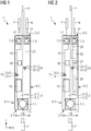
- FIG. 1 a topological plan view of the compact circuit breaker 1 according to the invention is shown schematically.
- the term “topology” refers to the basic division of the protective switching device 1 and the arrangement of the understood essential components.
- the protective switching device 1 has an insulating material housing 2, which in turn has a front side 3 and a fastening side 4 opposite the front side (see FIG Figures 2 and 3 ), as well as the front and the fastening side 3, 4 connecting narrow sides 5-1, 5-2 and broad sides 6-1, 6-2.
- the insulating housing 2 has a width of only one division unit (1TE) and is divided into a first section 2-1 and a second section 2-2, which extend in a longitudinal direction L from the first narrow side 5-1 to the second narrow side 5- 2 and are arranged one behind the other in a width direction B.
- the dividing line shown in dashed lines between the first section 2-1 and the second section 2-2 is not to be understood as a dividing wall running parallel to the broad sides 6-1 and 6-2, but merely as a schematic, imaginary dividing line.
- a partition to be formed between sections 2-1 and 2-2 would rather be based on the space requirements of the individual components of the protective switching device 1 which are to be arranged in the insulating housing 2.
- a first current path 10 is arranged in the first section 2-1, which electrically conductively connects a first input-side connection 11 arranged in the area of the first narrow side 5-1 to a first output-side connection 12 arranged in the area of the second narrow side 5-2.
- the first input-side connection 11 and the first output-side connection 12 serve to connect a first external connection conductor, the phase conductor P, to the first current path 10 of the protective switching device 1 in an electrically conductive manner.
- the protective switching device 1 shown is the first input-side connection 11 as connection terminal 7-1, the first output-side connection 12 as connection terminal 7-2, into which the phase conductor P is plugged in order to be clamped by tightening the screw and thus securely connected to the first current path will.
- the first narrow side 5-1 has a first opening 8-1 (see Figures 2 and 3 ) and the second narrow side 5-2 a second opening 8-2 (see Fig. 3 ) through each of which one end of the first phase conductor P is passed in order to be contacted by means of the connection terminals 7-1 and 7-2 arranged behind the openings 8-1 and 8-2.
- a second current path 20 is arranged, which connects a second input-side connection 21 to a second output-side connection 22 in an electrically conductive manner.
- the second input-side connection 21 and the second output-side connection 22 serve to connect a second external connection conductor, the neutral conductor N, to the second current path 20 of the protective switching device 1 in an electrically conductive manner.
- the second output-side connection 22 is also designed as a screw terminal 7-3 arranged in the area of the second narrow side 5-2
- the second input-side connection 21 is not designed as a connection terminal arranged in the area of the first narrow side 5-1, but is instead in the area of second narrow side 5-2 led out as a conductor from the insulating housing 2.
- connection terminal 7-1 in the area of the first narrow side 5-1 only one connection terminal 7-1 is arranged, which is made larger and can accordingly also be used for contacting a conventional busbar.
- busbars have pin-like connection elements at equidistant intervals from a dividing unit (1TE), with which series-mounted devices arranged next to one another can be contacted together quickly and easily.
- a dividing unit (1TE) with which series-mounted devices arranged next to one another can be contacted together quickly and easily.
- two-pole compact circuit breakers with a width of only one division unit (1TE) can be integrated into a busbar assembly and connected to one another, which significantly simplifies the installation effort.
- the connection terminals can be designed for this purpose, for example, as plug-in terminals or as screw terminals - but this is not essential to the invention.
- a first switching contact 13 is also arranged, with which the first current path 10 can be interrupted.
- the first switching contact 13 has a first fixed contact 13-1, which is electrically conductively connected to the first input-side connection 11, and a first moving contact 13-2, which is electrically connected to the first output-side connection 12.
- the first moving contact 13-2 can be moved relative to the first fixed contact 13-1, whereby the switching contact 13 can be opened and closed.
- a second switching contact 23 is arranged in the second current path 20, with which the second current path 20 can be interrupted.
- the second switching contact 23 has a second fixed contact 23-1 and a second moving contact 23-2, which are electrically conductively connected to the second input-side connection 21 and the second output-side connection 22.
- the second moving contact 23-2 can be moved relative to the second fixed contact 23-1, whereby the switching contact 23 can be opened and closed.
- first section 2-1 which is assigned to the first current path 10
- means 15 for detecting a short circuit and means 16 for detecting an overload are also arranged and held in the insulating material housing. These means 15 and 16 serve to detect a short circuit or an electrical overload in the circuit connected to the first current path 10, which is connected via the phase conductor P, and to interrupt the first circuit 10 by opening the first switching contact 13, whereby the affected circuit is disconnected from the mains.
- a compact circuit breaker of type "1 + N" can be implemented.
- Figure 2 shows the topology representation of the in Figure 1 circuit breaker 1 shown, but with extended functionality.
- means 15 for detecting a short circuit or means 16 for detecting an electrical overload must be equipped in the second section 2-2.
- means 25 for detecting a fault current and / or means 26 for detecting an accidental arc can be arranged in the second section 2-2 (as shown in dashed lines in FIG. 1). It is also possible to arrange means 27 for communication with other protective switching devices or with a superordinate unit, for example a control center, in the insulating material housing 2.
- the means 25 and 26 are used to detect a dangerous fault current and / or an arc fault and to open the switching contacts 13 and 23 by activating the switching mechanism of the protective switching device 1, whereby the relevant circuit connected to the protective switching device 1 is separated from the electrical supply network. If only the means 25 for detecting a fault current are included in the insulating material housing 2, combined protective switching devices such as FI / LS or RCBO can thereby be formed. By adding the means 26 for detecting an arc fault, the functionality of these combination devices can be expanded to include the functionality of a fire protection switch. However, it is also possible to additionally integrate only the means 26 for detecting an accidental arc in the insulating material housing 2 and in this way to implement a circuit breaker of the "1 + N" type with extended fire protection functionality.
- a compact combination circuit breaker 1 is shown schematically in two side views, the two broad sides 6-1 and 6-2 of the insulating housing 2 have been omitted in order to allow an insight into the interior of the housing.
- the protective switching device 1 corresponds to that in Figure 2 Compact circuit breaker 1 shown and described in detail above.
- Figure 3 consequently gives an insight into the second section 2-2, while in Figure 4 the first section 2-1 of the insulating housing 2 is shown.
- the means 15 for detecting a short circuit, the means 16 for detecting an overload, the means 25 for detecting a fault current and the means 26 for detecting an accidental arc can be seen:
- the means 15 for detecting a short circuit include, inter alia, a magnetic coil 15-1 and a plunger 15-2, which is movably mounted in the magnetic coil 15-1.
- the solenoid 15-1 is electrically connected between the first connection terminal 7-1 and the second connection terminal 7-2 and, in normal operation, the electric current flowing in the first current path 10 flows through it without the plunger 15-2 being actuated as a result.
- the means 16 for detecting an electrical overload have a thermal bimetal, which is also electrically connected between the first connection terminal 7-1 and the second connection terminal 7-2 - in series with the solenoid 15-1. If an overload current occurs above a predefined threshold value, this leads to a temperature-dependent Deformation of the thermal bimetal, which triggers the switching mechanism of the protective switching device 1 and, as a result, causes the first switching contact 13 to open. This also interrupts the flow of current in the first current path 10, and the protected circuit is separated from the electrical supply network.
- the means 25 for detecting a fault current contain a summation current transformer 25-1 through which the first current path 10, which is assigned to the phase conductor P, and the second current path 20, which is assigned to the neutral conductor N, are passed. In the event of an error, i.e. if a differential current occurs between the two current paths 10 and 20, this is recorded with the aid of the summation current transformer 25-1.
- a trip coil 25-2 is connected to the summation current transformer 25-1, which is energized when a fault current occurs and actuates a movably mounted plunger in order to activate the switching mechanism and to cause the first switching contact 13 and the second switching contact 23 to open .
- the means 25 for detecting a fault current are arranged in the second section 2-2.
- compact combination devices such as RCBO / FILS or LSDI can be implemented, which combine the functionality of a line circuit breaker with that of a residual current circuit breaker and are arranged in a narrow insulating material housing 2 with a width B of only one division unit (1TE).
- the means 26 for detecting an accidental arc have a measuring unit for measuring current and / or voltage, as well as an evaluation unit for analyzing the measured current and / or voltage signals. If an arc fault is detected, the switching mechanism is again activated in order to open the switching contacts 13 and 23 - and thus to separate the circuit from the electrical supply network.
- the means 26 for detecting an arc fault can be wholly or partially on a circuit board, which is equipped with the various electronic components for current and voltage analysis in order to enable analysis and evaluation with regard to the presence of an accidental arc.
- the means 26 for detecting an accidental arc are shown arranged in the second section 2-2.
- these means 26 it is also possible to arrange these means 26 entirely or partially in the first section 2-1.
- so-called rigid-flex printed circuit boards are conceivable, the rigid parts of which are connected to one another by flexible sections in order to achieve greater flexibility with regard to the spatial arrangement of both the printed circuit board and the other components of the protective switching device 1.
- parts of the means 25 for detecting a fault current and / or the means 27 for communication on the circuit board as well. In this way, compact combination devices such as RCBO / FILS or LSDI, expanded to include the functionality of a fire protection switch and, if necessary, an additional communication functionality, can be implemented.
Landscapes
- Breakers (AREA)
Applications Claiming Priority (1)
| Application Number | Priority Date | Filing Date | Title |
|---|---|---|---|
| DE202019001746.1U DE202019001746U1 (de) | 2019-04-17 | 2019-04-17 | Kompakt-Schutzschaltgerät |
Publications (1)
| Publication Number | Publication Date |
|---|---|
| EP3726560A1 true EP3726560A1 (fr) | 2020-10-21 |
Family
ID=66768124
Family Applications (1)
| Application Number | Title | Priority Date | Filing Date |
|---|---|---|---|
| EP20167008.0A Withdrawn EP3726560A1 (fr) | 2019-04-17 | 2020-03-31 | Disjoncteur de protection compact |
Country Status (3)
| Country | Link |
|---|---|
| EP (1) | EP3726560A1 (fr) |
| CN (1) | CN111834170A (fr) |
| DE (1) | DE202019001746U1 (fr) |
Cited By (2)
| Publication number | Priority date | Publication date | Assignee | Title |
|---|---|---|---|---|
| WO2022135799A1 (fr) * | 2020-12-21 | 2022-06-30 | Siemens Aktiengesellschaft | Procédé et dispositif disjoncteur |
| EP4064313A1 (fr) * | 2021-03-26 | 2022-09-28 | Schneider Electric Industries SAS | Dispositif de protection électrique et tableau électrique comprenant un tel dispositif de protection électrique |
Families Citing this family (1)
| Publication number | Priority date | Publication date | Assignee | Title |
|---|---|---|---|---|
| DE102024209258A1 (de) * | 2024-09-25 | 2026-03-26 | Siemens Aktiengesellschaft | Summenstromwandler-Baugruppe und Gerät zur Fehlerstromerfassung |
Citations (9)
| Publication number | Priority date | Publication date | Assignee | Title |
|---|---|---|---|---|
| EP1473750A1 (fr) | 2003-04-30 | 2004-11-03 | Siemens Aktiengesellschaft | Appareil interrupteur électromagnétique |
| DE102004034859A1 (de) | 2004-07-19 | 2006-02-16 | Siemens Ag | Schutzschaltgerät in Schmalbauweise |
| EP1191562B1 (fr) | 2000-09-21 | 2007-11-07 | Siemens Aktiengesellschaft | Disjoncteur à boîtier étroit avec dispositif de borne universel |
| EP2242080A2 (fr) * | 2009-04-18 | 2010-10-20 | General Electric Company | Ensemble de test pour disjoncteur |
| DE102014208564A1 (de) | 2014-05-07 | 2015-11-12 | Siemens Aktiengesellschaft | Schutzschaltgerät mit zwei Auslösemechaniken mit unterschiedlichen Hebelverhältnissen |
| CN102760622B (zh) * | 2012-07-23 | 2016-03-16 | 乐清市智顺电气有限公司 | 无加长宽度为18mm多功能漏电断路器 |
| EP3358594A1 (fr) | 2017-02-04 | 2018-08-08 | Siemens Aktiengesellschaft | Disjoncteur à un seul étage |
| WO2018141866A1 (fr) | 2017-02-04 | 2018-08-09 | Siemens Aktiengesellschaft | Disjoncteur mono-étage |
| EP3385974A1 (fr) * | 2017-04-06 | 2018-10-10 | Siemens Aktiengesellschaft | Disjoncteur différentiel |
Family Cites Families (3)
| Publication number | Priority date | Publication date | Assignee | Title |
|---|---|---|---|---|
| DE102016203506B4 (de) * | 2016-03-03 | 2021-10-07 | Siemens Aktiengesellschaft | Auslösevorrichtung und elektromechanisches Schutzschaltgerät |
| CN206312851U (zh) * | 2017-01-13 | 2017-07-07 | 包定 | 一种带过载保护的漏电断路器 |
| CN206697428U (zh) * | 2017-04-26 | 2017-12-01 | 胡永强 | 带过载短路漏电保护断路器 |
-
2019
- 2019-04-17 DE DE202019001746.1U patent/DE202019001746U1/de not_active Expired - Lifetime
-
2020
- 2020-03-31 EP EP20167008.0A patent/EP3726560A1/fr not_active Withdrawn
- 2020-04-17 CN CN202010304841.7A patent/CN111834170A/zh active Pending
Patent Citations (9)
| Publication number | Priority date | Publication date | Assignee | Title |
|---|---|---|---|---|
| EP1191562B1 (fr) | 2000-09-21 | 2007-11-07 | Siemens Aktiengesellschaft | Disjoncteur à boîtier étroit avec dispositif de borne universel |
| EP1473750A1 (fr) | 2003-04-30 | 2004-11-03 | Siemens Aktiengesellschaft | Appareil interrupteur électromagnétique |
| DE102004034859A1 (de) | 2004-07-19 | 2006-02-16 | Siemens Ag | Schutzschaltgerät in Schmalbauweise |
| EP2242080A2 (fr) * | 2009-04-18 | 2010-10-20 | General Electric Company | Ensemble de test pour disjoncteur |
| CN102760622B (zh) * | 2012-07-23 | 2016-03-16 | 乐清市智顺电气有限公司 | 无加长宽度为18mm多功能漏电断路器 |
| DE102014208564A1 (de) | 2014-05-07 | 2015-11-12 | Siemens Aktiengesellschaft | Schutzschaltgerät mit zwei Auslösemechaniken mit unterschiedlichen Hebelverhältnissen |
| EP3358594A1 (fr) | 2017-02-04 | 2018-08-08 | Siemens Aktiengesellschaft | Disjoncteur à un seul étage |
| WO2018141866A1 (fr) | 2017-02-04 | 2018-08-09 | Siemens Aktiengesellschaft | Disjoncteur mono-étage |
| EP3385974A1 (fr) * | 2017-04-06 | 2018-10-10 | Siemens Aktiengesellschaft | Disjoncteur différentiel |
Cited By (3)
| Publication number | Priority date | Publication date | Assignee | Title |
|---|---|---|---|---|
| WO2022135799A1 (fr) * | 2020-12-21 | 2022-06-30 | Siemens Aktiengesellschaft | Procédé et dispositif disjoncteur |
| EP4064313A1 (fr) * | 2021-03-26 | 2022-09-28 | Schneider Electric Industries SAS | Dispositif de protection électrique et tableau électrique comprenant un tel dispositif de protection électrique |
| FR3121273A1 (fr) * | 2021-03-26 | 2022-09-30 | Schneider Electric Industries Sas | Dispositif de protection électrique et tableau électrique comprenant un tel dispositif de protection électrique |
Also Published As
| Publication number | Publication date |
|---|---|
| DE202019001746U1 (de) | 2019-05-20 |
| CN111834170A (zh) | 2020-10-27 |
Similar Documents
| Publication | Publication Date | Title |
|---|---|---|
| EP2587513A1 (fr) | Commutateur d'installation doté d'une unité de capteur de courant | |
| EP3525227B1 (fr) | Appareil de commutation électrique à courant de défaut indépendant de la tension du réseau et procédé de montage | |
| DE202019001746U1 (de) | Kompakt-Schutzschaltgerät | |
| EP4131297B1 (fr) | Tiroir-transformateur sommateur de courant, disjoncteur-détecteur de fuites à la terre et procédé de montage | |
| EP4258310B1 (fr) | Module de boîtier, boîtier en matière isolante et appareil de commutation de protection | |
| EP4252266B1 (fr) | Boîtier d'isolation et disjoncteur compact | |
| DE102023202388A1 (de) | Geräte-Modul, Reiheneinbaugerät und Kontaktfeder | |
| EP2983191B1 (fr) | Système de détection d'arcs électriques parasites dans un réseau basse tension | |
| EP4213175B1 (fr) | Disjoncteur basse tension avec circuit imprime et prise de tension et procédé de montage | |
| EP4213174B1 (fr) | Module de boîtier unipolaire et disjoncteur basse tension | |
| DE102021208516A1 (de) | Summenstromwandler und Fehlerstromschutzschalter | |
| EP4445399A1 (fr) | Dispositif monté sur rail à commutation électronique et boîtier de matériau isolant | |
| EP4274041B1 (fr) | Boîtier isolant modulaire et appareil modulaire multipolaire à montage en série | |
| DE102014226221A1 (de) | Niederspannungs-Schutzschaltgerät und Anordnung zur Überwachung eines Stromkreises in einem Niederspannungsnetz | |
| DE102020200993A1 (de) | Fernantrieb, Anordnung mit einem Fernantrieb sowie Verfahren | |
| EP4138112A1 (fr) | Boîtier en matière isolante et disjoncteur de protection basse tension | |
| DE102018221033A1 (de) | Niederspannungs-Schutzschaltgerät | |
| EP4718485A1 (fr) | Ensemble transformateur sommateur et appareil de détection de courant de défaut | |
| DE102023201130A1 (de) | Kompakt-Reiheneinbaugerät sowie mehrpoliges Reiheneinbaugerät | |
| EP3168851B1 (fr) | Dispositif d'isolation et disjoncteur électromécanique | |
| DE102023204547A1 (de) | Modular gebildetes mehrpoliges Reiheneinbaugerät | |
| EP4312243A1 (fr) | Ensemble transformateur sommateur de courant à tiroir, appareil à montage en série et procédé d'assemblage | |
| WO2024041855A1 (fr) | Dispositif modulaire monté sur rail multipolaire | |
| WO2024046795A1 (fr) | Disjoncteur et procédé | |
| WO2024046809A1 (fr) | Disjoncteur et procédé |
Legal Events
| Date | Code | Title | Description |
|---|---|---|---|
| PUAI | Public reference made under article 153(3) epc to a published international application that has entered the european phase |
Free format text: ORIGINAL CODE: 0009012 |
|
| STAA | Information on the status of an ep patent application or granted ep patent |
Free format text: STATUS: THE APPLICATION HAS BEEN PUBLISHED |
|
| AK | Designated contracting states |
Kind code of ref document: A1 Designated state(s): AL AT BE BG CH CY CZ DE DK EE ES FI FR GB GR HR HU IE IS IT LI LT LU LV MC MK MT NL NO PL PT RO RS SE SI SK SM TR |
|
| AX | Request for extension of the european patent |
Extension state: BA ME |
|
| STAA | Information on the status of an ep patent application or granted ep patent |
Free format text: STATUS: THE APPLICATION IS DEEMED TO BE WITHDRAWN |
|
| 18D | Application deemed to be withdrawn |
Effective date: 20210422 |