EP3726563A1 - Filmbildungsvorrichtung - Google Patents
Filmbildungsvorrichtung Download PDFInfo
- Publication number
- EP3726563A1 EP3726563A1 EP18887844.1A EP18887844A EP3726563A1 EP 3726563 A1 EP3726563 A1 EP 3726563A1 EP 18887844 A EP18887844 A EP 18887844A EP 3726563 A1 EP3726563 A1 EP 3726563A1
- Authority
- EP
- European Patent Office
- Prior art keywords
- substrate
- stage
- rotary shaft
- film forming
- gas
- Prior art date
- Legal status (The legal status is an assumption and is not a legal conclusion. Google has not performed a legal analysis and makes no representation as to the accuracy of the status listed.)
- Withdrawn
Links
Images


Classifications
-
- H—ELECTRICITY
- H10—SEMICONDUCTOR DEVICES; ELECTRIC SOLID-STATE DEVICES NOT OTHERWISE PROVIDED FOR
- H10P—GENERIC PROCESSES OR APPARATUS FOR THE MANUFACTURE OR TREATMENT OF DEVICES COVERED BY CLASS H10
- H10P72/00—Handling or holding of wafers, substrates or devices during manufacture or treatment thereof
- H10P72/70—Handling or holding of wafers, substrates or devices during manufacture or treatment thereof for supporting or gripping
-
- H—ELECTRICITY
- H10—SEMICONDUCTOR DEVICES; ELECTRIC SOLID-STATE DEVICES NOT OTHERWISE PROVIDED FOR
- H10P—GENERIC PROCESSES OR APPARATUS FOR THE MANUFACTURE OR TREATMENT OF DEVICES COVERED BY CLASS H10
- H10P72/00—Handling or holding of wafers, substrates or devices during manufacture or treatment thereof
- H10P72/70—Handling or holding of wafers, substrates or devices during manufacture or treatment thereof for supporting or gripping
- H10P72/76—Handling or holding of wafers, substrates or devices during manufacture or treatment thereof for supporting or gripping using mechanical means, e.g. clamps or pinches
- H10P72/7604—Handling or holding of wafers, substrates or devices during manufacture or treatment thereof for supporting or gripping using mechanical means, e.g. clamps or pinches the wafers being placed on a susceptor, stage or support
- H10P72/7616—Handling or holding of wafers, substrates or devices during manufacture or treatment thereof for supporting or gripping using mechanical means, e.g. clamps or pinches the wafers being placed on a susceptor, stage or support characterised by a coating, a hardness or a material
-
- C—CHEMISTRY; METALLURGY
- C23—COATING METALLIC MATERIAL; COATING MATERIAL WITH METALLIC MATERIAL; CHEMICAL SURFACE TREATMENT; DIFFUSION TREATMENT OF METALLIC MATERIAL; COATING BY VACUUM EVAPORATION, BY SPUTTERING, BY ION IMPLANTATION OR BY CHEMICAL VAPOUR DEPOSITION, IN GENERAL; INHIBITING CORROSION OF METALLIC MATERIAL OR INCRUSTATION IN GENERAL
- C23C—COATING METALLIC MATERIAL; COATING MATERIAL WITH METALLIC MATERIAL; SURFACE TREATMENT OF METALLIC MATERIAL BY DIFFUSION INTO THE SURFACE, BY CHEMICAL CONVERSION OR SUBSTITUTION; COATING BY VACUUM EVAPORATION, BY SPUTTERING, BY ION IMPLANTATION OR BY CHEMICAL VAPOUR DEPOSITION, IN GENERAL
- C23C16/00—Chemical coating by decomposition of gaseous compounds, without leaving reaction products of surface material in the coating, i.e. chemical vapour deposition [CVD] processes
- C23C16/22—Chemical coating by decomposition of gaseous compounds, without leaving reaction products of surface material in the coating, i.e. chemical vapour deposition [CVD] processes characterised by the deposition of inorganic material, other than metallic material
- C23C16/30—Deposition of compounds, mixtures or solid solutions, e.g. borides, carbides, nitrides
- C23C16/32—Carbides
- C23C16/325—Silicon carbide
-
- C—CHEMISTRY; METALLURGY
- C23—COATING METALLIC MATERIAL; COATING MATERIAL WITH METALLIC MATERIAL; CHEMICAL SURFACE TREATMENT; DIFFUSION TREATMENT OF METALLIC MATERIAL; COATING BY VACUUM EVAPORATION, BY SPUTTERING, BY ION IMPLANTATION OR BY CHEMICAL VAPOUR DEPOSITION, IN GENERAL; INHIBITING CORROSION OF METALLIC MATERIAL OR INCRUSTATION IN GENERAL
- C23C—COATING METALLIC MATERIAL; COATING MATERIAL WITH METALLIC MATERIAL; SURFACE TREATMENT OF METALLIC MATERIAL BY DIFFUSION INTO THE SURFACE, BY CHEMICAL CONVERSION OR SUBSTITUTION; COATING BY VACUUM EVAPORATION, BY SPUTTERING, BY ION IMPLANTATION OR BY CHEMICAL VAPOUR DEPOSITION, IN GENERAL
- C23C16/00—Chemical coating by decomposition of gaseous compounds, without leaving reaction products of surface material in the coating, i.e. chemical vapour deposition [CVD] processes
- C23C16/44—Chemical coating by decomposition of gaseous compounds, without leaving reaction products of surface material in the coating, i.e. chemical vapour deposition [CVD] processes characterised by the method of coating
- C23C16/458—Chemical coating by decomposition of gaseous compounds, without leaving reaction products of surface material in the coating, i.e. chemical vapour deposition [CVD] processes characterised by the method of coating characterised by the method used for supporting substrates in the reaction chamber
-
- C—CHEMISTRY; METALLURGY
- C23—COATING METALLIC MATERIAL; COATING MATERIAL WITH METALLIC MATERIAL; CHEMICAL SURFACE TREATMENT; DIFFUSION TREATMENT OF METALLIC MATERIAL; COATING BY VACUUM EVAPORATION, BY SPUTTERING, BY ION IMPLANTATION OR BY CHEMICAL VAPOUR DEPOSITION, IN GENERAL; INHIBITING CORROSION OF METALLIC MATERIAL OR INCRUSTATION IN GENERAL
- C23C—COATING METALLIC MATERIAL; COATING MATERIAL WITH METALLIC MATERIAL; SURFACE TREATMENT OF METALLIC MATERIAL BY DIFFUSION INTO THE SURFACE, BY CHEMICAL CONVERSION OR SUBSTITUTION; COATING BY VACUUM EVAPORATION, BY SPUTTERING, BY ION IMPLANTATION OR BY CHEMICAL VAPOUR DEPOSITION, IN GENERAL
- C23C16/00—Chemical coating by decomposition of gaseous compounds, without leaving reaction products of surface material in the coating, i.e. chemical vapour deposition [CVD] processes
- C23C16/44—Chemical coating by decomposition of gaseous compounds, without leaving reaction products of surface material in the coating, i.e. chemical vapour deposition [CVD] processes characterised by the method of coating
- C23C16/458—Chemical coating by decomposition of gaseous compounds, without leaving reaction products of surface material in the coating, i.e. chemical vapour deposition [CVD] processes characterised by the method of coating characterised by the method used for supporting substrates in the reaction chamber
- C23C16/4581—Chemical coating by decomposition of gaseous compounds, without leaving reaction products of surface material in the coating, i.e. chemical vapour deposition [CVD] processes characterised by the method of coating characterised by the method used for supporting substrates in the reaction chamber characterised by material of construction or surface finish of the means for supporting the substrate
-
- C—CHEMISTRY; METALLURGY
- C23—COATING METALLIC MATERIAL; COATING MATERIAL WITH METALLIC MATERIAL; CHEMICAL SURFACE TREATMENT; DIFFUSION TREATMENT OF METALLIC MATERIAL; COATING BY VACUUM EVAPORATION, BY SPUTTERING, BY ION IMPLANTATION OR BY CHEMICAL VAPOUR DEPOSITION, IN GENERAL; INHIBITING CORROSION OF METALLIC MATERIAL OR INCRUSTATION IN GENERAL
- C23C—COATING METALLIC MATERIAL; COATING MATERIAL WITH METALLIC MATERIAL; SURFACE TREATMENT OF METALLIC MATERIAL BY DIFFUSION INTO THE SURFACE, BY CHEMICAL CONVERSION OR SUBSTITUTION; COATING BY VACUUM EVAPORATION, BY SPUTTERING, BY ION IMPLANTATION OR BY CHEMICAL VAPOUR DEPOSITION, IN GENERAL
- C23C16/00—Chemical coating by decomposition of gaseous compounds, without leaving reaction products of surface material in the coating, i.e. chemical vapour deposition [CVD] processes
- C23C16/44—Chemical coating by decomposition of gaseous compounds, without leaving reaction products of surface material in the coating, i.e. chemical vapour deposition [CVD] processes characterised by the method of coating
- C23C16/458—Chemical coating by decomposition of gaseous compounds, without leaving reaction products of surface material in the coating, i.e. chemical vapour deposition [CVD] processes characterised by the method of coating characterised by the method used for supporting substrates in the reaction chamber
- C23C16/4582—Rigid and flat substrates, e.g. plates or discs
- C23C16/4583—Rigid and flat substrates, e.g. plates or discs the substrate being supported substantially horizontally
- C23C16/4584—Rigid and flat substrates, e.g. plates or discs the substrate being supported substantially horizontally the substrate being rotated
-
- C—CHEMISTRY; METALLURGY
- C23—COATING METALLIC MATERIAL; COATING MATERIAL WITH METALLIC MATERIAL; CHEMICAL SURFACE TREATMENT; DIFFUSION TREATMENT OF METALLIC MATERIAL; COATING BY VACUUM EVAPORATION, BY SPUTTERING, BY ION IMPLANTATION OR BY CHEMICAL VAPOUR DEPOSITION, IN GENERAL; INHIBITING CORROSION OF METALLIC MATERIAL OR INCRUSTATION IN GENERAL
- C23C—COATING METALLIC MATERIAL; COATING MATERIAL WITH METALLIC MATERIAL; SURFACE TREATMENT OF METALLIC MATERIAL BY DIFFUSION INTO THE SURFACE, BY CHEMICAL CONVERSION OR SUBSTITUTION; COATING BY VACUUM EVAPORATION, BY SPUTTERING, BY ION IMPLANTATION OR BY CHEMICAL VAPOUR DEPOSITION, IN GENERAL
- C23C16/00—Chemical coating by decomposition of gaseous compounds, without leaving reaction products of surface material in the coating, i.e. chemical vapour deposition [CVD] processes
- C23C16/44—Chemical coating by decomposition of gaseous compounds, without leaving reaction products of surface material in the coating, i.e. chemical vapour deposition [CVD] processes characterised by the method of coating
- C23C16/458—Chemical coating by decomposition of gaseous compounds, without leaving reaction products of surface material in the coating, i.e. chemical vapour deposition [CVD] processes characterised by the method of coating characterised by the method used for supporting substrates in the reaction chamber
- C23C16/4582—Rigid and flat substrates, e.g. plates or discs
- C23C16/4583—Rigid and flat substrates, e.g. plates or discs the substrate being supported substantially horizontally
- C23C16/4586—Elements in the interior of the support, e.g. electrodes, heating or cooling devices
-
- C—CHEMISTRY; METALLURGY
- C23—COATING METALLIC MATERIAL; COATING MATERIAL WITH METALLIC MATERIAL; CHEMICAL SURFACE TREATMENT; DIFFUSION TREATMENT OF METALLIC MATERIAL; COATING BY VACUUM EVAPORATION, BY SPUTTERING, BY ION IMPLANTATION OR BY CHEMICAL VAPOUR DEPOSITION, IN GENERAL; INHIBITING CORROSION OF METALLIC MATERIAL OR INCRUSTATION IN GENERAL
- C23C—COATING METALLIC MATERIAL; COATING MATERIAL WITH METALLIC MATERIAL; SURFACE TREATMENT OF METALLIC MATERIAL BY DIFFUSION INTO THE SURFACE, BY CHEMICAL CONVERSION OR SUBSTITUTION; COATING BY VACUUM EVAPORATION, BY SPUTTERING, BY ION IMPLANTATION OR BY CHEMICAL VAPOUR DEPOSITION, IN GENERAL
- C23C16/00—Chemical coating by decomposition of gaseous compounds, without leaving reaction products of surface material in the coating, i.e. chemical vapour deposition [CVD] processes
- C23C16/44—Chemical coating by decomposition of gaseous compounds, without leaving reaction products of surface material in the coating, i.e. chemical vapour deposition [CVD] processes characterised by the method of coating
- C23C16/46—Chemical coating by decomposition of gaseous compounds, without leaving reaction products of surface material in the coating, i.e. chemical vapour deposition [CVD] processes characterised by the method of coating characterised by the method used for heating the substrate
-
- C—CHEMISTRY; METALLURGY
- C30—CRYSTAL GROWTH
- C30B—SINGLE-CRYSTAL GROWTH; UNIDIRECTIONAL SOLIDIFICATION OF EUTECTIC MATERIAL OR UNIDIRECTIONAL DEMIXING OF EUTECTOID MATERIAL; REFINING BY ZONE-MELTING OF MATERIAL; PRODUCTION OF A HOMOGENEOUS POLYCRYSTALLINE MATERIAL WITH DEFINED STRUCTURE; SINGLE CRYSTALS OR HOMOGENEOUS POLYCRYSTALLINE MATERIAL WITH DEFINED STRUCTURE; AFTER-TREATMENT OF SINGLE CRYSTALS OR A HOMOGENEOUS POLYCRYSTALLINE MATERIAL WITH DEFINED STRUCTURE; APPARATUS THEREFOR
- C30B25/00—Single-crystal growth by chemical reaction of reactive gases, e.g. chemical vapour-deposition growth
- C30B25/02—Epitaxial-layer growth
- C30B25/10—Heating of the reaction chamber or the substrate
-
- H—ELECTRICITY
- H10—SEMICONDUCTOR DEVICES; ELECTRIC SOLID-STATE DEVICES NOT OTHERWISE PROVIDED FOR
- H10P—GENERIC PROCESSES OR APPARATUS FOR THE MANUFACTURE OR TREATMENT OF DEVICES COVERED BY CLASS H10
- H10P14/00—Formation of materials, e.g. in the shape of layers or pillars
- H10P14/20—Formation of materials, e.g. in the shape of layers or pillars of semiconductor materials
- H10P14/29—Formation of materials, e.g. in the shape of layers or pillars of semiconductor materials characterised by the substrates
- H10P14/2901—Materials
- H10P14/2902—Materials being Group IVA materials
- H10P14/2904—Silicon carbide
-
- H—ELECTRICITY
- H10—SEMICONDUCTOR DEVICES; ELECTRIC SOLID-STATE DEVICES NOT OTHERWISE PROVIDED FOR
- H10P—GENERIC PROCESSES OR APPARATUS FOR THE MANUFACTURE OR TREATMENT OF DEVICES COVERED BY CLASS H10
- H10P72/00—Handling or holding of wafers, substrates or devices during manufacture or treatment thereof
- H10P72/04—Apparatus for manufacture or treatment
- H10P72/0431—Apparatus for thermal treatment
- H10P72/0436—Apparatus for thermal treatment mainly by radiation
-
- H—ELECTRICITY
- H10—SEMICONDUCTOR DEVICES; ELECTRIC SOLID-STATE DEVICES NOT OTHERWISE PROVIDED FOR
- H10P—GENERIC PROCESSES OR APPARATUS FOR THE MANUFACTURE OR TREATMENT OF DEVICES COVERED BY CLASS H10
- H10P72/00—Handling or holding of wafers, substrates or devices during manufacture or treatment thereof
- H10P72/70—Handling or holding of wafers, substrates or devices during manufacture or treatment thereof for supporting or gripping
- H10P72/76—Handling or holding of wafers, substrates or devices during manufacture or treatment thereof for supporting or gripping using mechanical means, e.g. clamps or pinches
- H10P72/7604—Handling or holding of wafers, substrates or devices during manufacture or treatment thereof for supporting or gripping using mechanical means, e.g. clamps or pinches the wafers being placed on a susceptor, stage or support
- H10P72/7612—Handling or holding of wafers, substrates or devices during manufacture or treatment thereof for supporting or gripping using mechanical means, e.g. clamps or pinches the wafers being placed on a susceptor, stage or support characterised by lifting arrangements, e.g. lift pins
-
- H—ELECTRICITY
- H10—SEMICONDUCTOR DEVICES; ELECTRIC SOLID-STATE DEVICES NOT OTHERWISE PROVIDED FOR
- H10P—GENERIC PROCESSES OR APPARATUS FOR THE MANUFACTURE OR TREATMENT OF DEVICES COVERED BY CLASS H10
- H10P72/00—Handling or holding of wafers, substrates or devices during manufacture or treatment thereof
- H10P72/70—Handling or holding of wafers, substrates or devices during manufacture or treatment thereof for supporting or gripping
- H10P72/76—Handling or holding of wafers, substrates or devices during manufacture or treatment thereof for supporting or gripping using mechanical means, e.g. clamps or pinches
- H10P72/7604—Handling or holding of wafers, substrates or devices during manufacture or treatment thereof for supporting or gripping using mechanical means, e.g. clamps or pinches the wafers being placed on a susceptor, stage or support
- H10P72/7626—Handling or holding of wafers, substrates or devices during manufacture or treatment thereof for supporting or gripping using mechanical means, e.g. clamps or pinches the wafers being placed on a susceptor, stage or support characterised by the construction of the shaft
-
- H—ELECTRICITY
- H10—SEMICONDUCTOR DEVICES; ELECTRIC SOLID-STATE DEVICES NOT OTHERWISE PROVIDED FOR
- H10P—GENERIC PROCESSES OR APPARATUS FOR THE MANUFACTURE OR TREATMENT OF DEVICES COVERED BY CLASS H10
- H10P14/00—Formation of materials, e.g. in the shape of layers or pillars
- H10P14/20—Formation of materials, e.g. in the shape of layers or pillars of semiconductor materials
- H10P14/24—Formation of materials, e.g. in the shape of layers or pillars of semiconductor materials using chemical vapour deposition [CVD]
-
- H—ELECTRICITY
- H10—SEMICONDUCTOR DEVICES; ELECTRIC SOLID-STATE DEVICES NOT OTHERWISE PROVIDED FOR
- H10P—GENERIC PROCESSES OR APPARATUS FOR THE MANUFACTURE OR TREATMENT OF DEVICES COVERED BY CLASS H10
- H10P14/00—Formation of materials, e.g. in the shape of layers or pillars
- H10P14/20—Formation of materials, e.g. in the shape of layers or pillars of semiconductor materials
- H10P14/34—Deposited materials, e.g. layers
- H10P14/3402—Deposited materials, e.g. layers characterised by the chemical composition
- H10P14/3404—Deposited materials, e.g. layers characterised by the chemical composition being Group IVA materials
- H10P14/3408—Silicon carbide
-
- H—ELECTRICITY
- H10—SEMICONDUCTOR DEVICES; ELECTRIC SOLID-STATE DEVICES NOT OTHERWISE PROVIDED FOR
- H10P—GENERIC PROCESSES OR APPARATUS FOR THE MANUFACTURE OR TREATMENT OF DEVICES COVERED BY CLASS H10
- H10P14/00—Formation of materials, e.g. in the shape of layers or pillars
- H10P14/20—Formation of materials, e.g. in the shape of layers or pillars of semiconductor materials
- H10P14/34—Deposited materials, e.g. layers
- H10P14/3438—Doping during depositing
- H10P14/3441—Conductivity type
- H10P14/3444—P-type
Definitions
- the present disclosure relates to a film forming apparatus that performs a film forming process on a target substrate.
- a semiconductor manufactured using a compound such as silicon carbide (SiC) or the like has been used for an electronic device such as a semiconductor power device or the like.
- a compound semiconductor film such as a SiC film or the like is formed by epitaxial growth in which a film having the same orientation relationship as a substrate crystal is grown on a monocrystalline substrate.
- Patent document 1 discloses, as an apparatus for forming a SiC film by epitaxial growth, an apparatus that includes a stage on which a SiC substrate as a target substrate is placed, a rotary shaft part that rotatably supports the stage, and a susceptor having an internal space for accommodating the stage.
- the SiC film is formed on the SiC substrate by supplying a processing gas to the SiC substrate on the stage inside the susceptor while heating the SiC substrate by inductively heating the susceptor.
- the film forming apparatus of Patent Document 1 includes a heat insulating material provided between the susceptor and the stage.
- a heat insulating region provided with the heat insulating material is formed between the central region including the rotary shaft part inside the susceptor and the peripheral region in a plan view.
- the stage tends to have a low temperature in the central region and the peripheral region.
- the heat insulating region is formed as described above, and the temperature of the stage above the heat insulating region is reduced, thereby reducing the temperature variation in the plane of the SiC substrate on the stage.
- Patent Document 1 Japanese laid-open publication No. 2016-100462
- the film forming apparatus of Patent Document 1 has room for improvement in terms of heating efficiency because the heat insulating material is provided between the susceptor as a heating source and the stage as an object to be heated. In addition, the heat of the stage escapes through the rotary shaft part connected to the center of the stage. This leads to a problem in that the in-plane temperature distribution of the stage becomes non-uniform, and thus, the in-plane temperature distribution of the target substrate becomes non-uniform.
- the present disclosure provides some embodiments of a film forming apparatus capable of reducing a temperature variation in the plane of a target substrate with high heating efficiency.
- a film forming apparatus for heating a target substrate on a stage, supplying a processing gas to the target substrate, and performing a film forming process on the target substrate, including: an accommodation part having an internal space for accommodating the stage, wherein the processing gas is supplied to the internal space and is inductively heated; a rotary shaft part configured to rotatably support the stage; and an elevating part configured to raise and lower the target substrate to deliver the target substrate between an external substrate transfer device and the stage, wherein the rotary shaft part and/or the elevating part is formed of a material having a thermal conductivity of 15 W/m ⁇ K or less and a melting point of 1,800 degrees C or higher.
- a heat insulating material is not provided between the susceptor serving as a heating source and the stage serving as a heated object. Therefore, it is possible to heat the target substrate with high heating efficiency. Furthermore, since the rotary shaft part and/or the elevating part are formed of a material having a thermal conductivity of 15 W/m K or less, the temperature at the center of the stage does not decrease. Therefore, as compared with a case where the rotary shaft part and the like are formed of a material having a high thermal conductivity, it is possible to reduce the temperature difference between the central region of the stage and the region around the central region of the stage. Thus, it is possible to reduce the temperature variation in the plane of the target substrate.
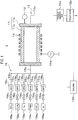
- FIG. 1 is a view schematically showing an outline of a configuration of a film forming apparatus according to an embodiment of the present disclosure.
- a film forming apparatus 1 in FIG. 1 includes a substantially rectangular parallelepiped processing container 11.
- An exhaust line 12 is connected to the processing container 11.
- the processing container 11 can be adjusted to be maintained in a predetermined depressurized state (pressure) through the exhaust line 12.
- the exhaust line 12 is provided with an exhaust pipe 12a having one end connected to the processing container 11.
- the exhaust pipe 12a is configured by an exhaust manifold and the like, and includes a vacuum pump 12b such as a mechanical booster pump or the like connected to the side of the exhaust pipe 12a opposite the processing container 11.
- a pressure regulation part 12c composed of an APC (automatic pressure control) valve, a proportional control valve or the like and configured to regulate an internal pressure of the processing container 11. Furthermore, a pressure gauge 13 is provided in the processing container 11. The regulation of the internal pressure of the processing container 11 by the pressure regulation part 12c is performed based on the measurement result of the pressure gauge 13.
- the processing container 11 includes a hollow rectangular column-shaped processing container body 11a having openings at both ends thereof, and sidewall portions 11b connected to the both ends of the processing container body 11a so as to close the openings.
- the processing container body 11a and the sidewall portions 11b are made of a dielectric material such as quartz or the like.
- a coil 14 connected to a high-frequency power source 14a is provided outside the processing container body 11a.
- the coil 14 inductively heats a target substrate, a susceptor 23 (to be described later) and the like inside the processing container 11.
- the processing container 11 is configured so that a raw material gas serving as a raw material for film formation or the like is supplied into the processing container 11 by a gas supply line 15.
- the gas supply line 15 includes a gas supply pipe 15a connected to the processing container 11, and gas supply pipes 15b 1 to 15b 6 connected to the gas supply pipe 15a.
- the gas supply pipes 15b 1 to 15b 6 are provided with mass flow controllers (MFCs) 15c 1 to 15c 6 and valves 15d 1 to 15d 6 , respectively.
- a gas source 15e 1 is connected to the gas supply pipe 15bi, and a SiH 4 gas is supplied from the gas source 15ei.
- gas sources 15e 2 to 15e 6 are connected to the gas lines 15b 2 to 15b 6 , respectively.
- a C 3 H 8 gas, a H 2 gas, a TMA (trimethylaluminum) gas, a ClF 3 gas and an Ar gas are supplied from the respective gas sources 15e 2 to 15e 6 .
- the SiH 4 gas, the C 3 H 8 gas, the H 2 gas and the TMA gas as raw material gases for film formation are supplied from the respective gas supply pipes 15b 1 to 15b 4 into the processing container 11.
- a gas source and a gas supply pipe for an N 2 gas may be provided to form an n-type SiC film.
- one of the ClF 3 gas, the H 2 gas and the Ar gas or a mixture of two or more of these gases is supplied from the gas supply pipes 15b 3 , 15bs and 15b 6 into the processing container 11.
- the film forming apparatus 1 includes a controller 100.
- the controller 100 is, for example, a computer, and includes a program storage part (not shown).
- the program storage part stores programs for executing a film forming process by controlling the MFCs 15c 1 to 15c 6 , the valves 15d 1 to 15d 6 , the high-frequency power source 14a, the pressure regulation part 12c, a below-described rotary driving part, a below-described vertical driving part, and the like.
- the above programs may be recorded in a computer-readable storage medium such as, for example, a computer-readable hard disk (HD), a flexible disk (FD), a compact disk (CD), a magneto-optical disk (MO), a memory card or the like, and may be installed on the controller 100 from the storage medium.
- a computer-readable storage medium such as, for example, a computer-readable hard disk (HD), a flexible disk (FD), a compact disk (CD), a magneto-optical disk (MO), a memory card or the like, and may be installed on the controller 100 from the storage medium.
- FIG. 2 is a sectional view schematically showing an outline of the internal configuration of the processing container 11 in the film forming apparatus 1 of FIG. 1 .
- a susceptor 23 as an accommodation part is provided inside the processing container 11.
- the susceptor 23 has an internal space for accommodating the stage 20. A processing gas is supplied into the internal space so that the processing gas flows from one end of the stage 20 to the other end of the stage 20 through the center of the stage 20.
- the holder H is configured to collectively load and unload a plurality of substrates W into and out of the film forming apparatus 1 and is configured to hold the plurality of substrates W. Furthermore, the holder H is formed of a conductive material which has high heat resistance and which can be easily heated by inductive heating. For example, the holder H is formed of a graphite-made member whose upper surface on which the substrates W are placed is coated with SiC. The holder H is formed in, for example, a disk shape having a smaller diameter than the stage 20.
- the stage 20 is formed in a disk shape having a downwardly-recessed concave portion 20a formed on the upper surface thereof, and is provided horizontally inside the processing container 11.
- the holder H fits into the concave portion 20a.
- a downwardly-recessed depression 20b is formed at the center of the bottom of the concave portion 20a.
- a support portion 22a described later fits into the depression 20b.
- the stage 20 is made of a conductive material which has high heat resistance and which can be easily heated by inductive heating.
- the stage 20 is formed of, for example, a graphite-made member whose upper surface is coated with SiC.
- One end of the rotary shaft part 21 is connected to the center of the lower portion of the stage 20, and the other end thereof penetrates through the bottom of the processing container 11 and extends downward.
- the rotary shaft part 21 is connected to a rotary driving mechanism (not shown). As the rotary shaft part 21 is rotated by the rotary driving mechanism, the stage 20 is rotated.
- the rotary shaft part 21 is formed of a material having a relatively low thermal conductivity and a relatively high electrical resistivity. Specifically, the rotary shaft part 21 is formed of a material having a thermal conductivity of 15 W/m ⁇ K or less, a melting point of 1,800 degrees C or more and an electrical resistivity of 10 to 50 ⁇ m. More specifically, the rotary shaft part 21 is formed of a carbon-fiber-reinforced carbon composite material. As the carbon-fiber-reinforced carbon composite material, it may be possible to use, for example, CX-31 manufactured by Toyo Tanso Co., Ltd.
- the rotary shaft part 21 is formed so that the direction perpendicular to the fiber axis and the axial direction of the rotary shaft part 21 are parallel.
- the elevating part 22 is used for delivering the substrates W between a substrate transfer device provided outside the film forming apparatus 1 and the stage 20.
- the elevating part 22 delivers the holder H on which the substrates W are placed.
- the elevating part 22 includes the support portion 22a formed in a disc shape smaller in diameter than the holder H and configured to support the holder H, and an elevating shaft 22b connected to the lower surface of the support portion 22a and configured to raise and lower the support portion 22a.
- the elevating shaft 22b is raised and lowered by a vertical driving mechanism (not shown) so that the holder H (namely the substrates W) is raised and lowered.
- the support portion 22a and the elevating shaft 22b are formed of the same material as that of the rotary shaft part 21.
- the rotary shaft part 21, the support portion 22a and the elevating shaft 22b with a material having a thermal conductivity of 15 W/m K or less, such as a carbon-fiber-reinforced carbon composite material, it is possible to improve the in-plane uniformity of the temperature of the substrates W.
- the susceptor 23 is formed in a rectangular parallelepiped shape having openings formed in two surfaces facing each other, and has a structure in which a processing gas is supplied from the opening formed in one surface and is discharged from the opening formed in the other surface. In this structure, the processing gas supplied to the substrates W are supplied and discharged along a direction parallel to the substrates W.
- the susceptor 23 is made of a conductive material which has a high heat resistance and which can be easily heated by inductive heating.
- the susceptor 23 is formed of a graphite-made member whose surface on the side of the substrate W is coated with SiC.
- a heat insulating material 24 for insulating the susceptor 23 and the processing container 11 from each other is provided on the outer periphery of the susceptor 23.
- the heat insulating material 24 is formed by using, for example, a fibrous carbon material having a high porosity.
- a holding structure for holding the heat insulating material 24 while keeping the heat insulating material 24 spaced apart from the processing container 11 is provided outside the heat insulating material 24.
- the holder H on which the substrates W are placed is loaded into the processing container 11 (step S1). Specifically, the holder H is loaded from the outside of the film forming apparatus 1 into the processing container 11 via a gate valve (not shown) by using a transfer means (not shown) provided outside the film forming apparatus 1, and is positioned above the stage 20. Subsequently, the elevating part 22 is raised to support the holder H with the support portion 22a. Then, the transfer means is retracted from the processing container 11, and the elevating part is lowered to place the holder H on the stage 20.
- a raw material gas is supplied into the processing container 11, and the substrate W is heated by applying high-frequency power from the high-frequency power source 14a to the coil 14, thereby forming a p-type SiC film on the substrates W by epitaxial growth (step S2).
- the valves 15d 1 to 15d 4 are opened, and the SiH 4 gas, the C 3 H 8 gas, the H 2 gas and the TMA gas are supplied into the processing container 11 while adjusting the flow rates of the gases by the MFCs 15c 1 to 15c 4 .
- the substrate W is heated by radiation or heat conduction generated from the holder H, the stage 20 and the susceptor 23, which have been inductively heated.
- the internal pressure of the processing container 11 is, for example, 10 Torr to 600 Torr, and the temperature of the substrate W is, for example, 1,500 degrees C to 1,700 degrees C.
- the holder H supporting the substrates W is unloaded out of the processing container 11 (step S3). Specifically, after closing the valves 15d 1 to 15d 4 to stop the supply of the raw material gases, the elevating part 22 is raised to raise the holder H on which the substrates W are supported. Then, the transfer means outside the film forming apparatus 1 is inserted into the processing container 11 via the gate valve, and is positioned below the support portion 22a of the elevating part 22. Thereafter, the elevating part 22 is lowered, the holder H is delivered from the support portion 22a to the transfer means, and the transfer means is retracted from the processing container 11, whereby the holder H holding the substrates W is unloaded from the processing container 11.
- the supply of the high-frequency power to the coil 14 may be interrupted during the unloading of the substrates W, it is preferred that the high-frequency power is supplied to the coil 14 while controlling the temperature of the stage 20 and the susceptor 23 to be optimal in a subsequent step.
- step S1 After the unloading of the holder H, the process returns to step S1 in which the holder H on which other substrates W are placed is loaded into the processing container 11. The processes of steps S1 to S3 are repeated.
- the effects of the film forming apparatus 1 of the present embodiment will be described.
- an apparatus for forming a SiC film with the same configuration as that of the film forming apparatus 1 it is known that the temperature of the stage and the temperature of the holder are low in a central region in a plan view (hereinafter abbreviated as central region).
- the present inventors have conducted intensive studies and found that one of the causes of the low temperature of the stage and the low temperature of the holder in the central region is a material of the member located in the central region. Details thereof are as follows.
- those components corresponding to the rotary shaft part 21 and the elevating part 22 located in the central region of the film forming apparatus 1 of the present embodiment are formed of SiC or graphite.
- the thermal conductivity of SiC or graphite is lower than that of a metallic material or the like, it is at a relatively high level of 100 W/m ⁇ K or more. Therefore, in the conventional film forming apparatus, even if the stage or the holder is heated, the heat of the central portion of the stage or the holder is dissipated through the rotary shaft part and the elevating part. As a result, it is considered that the temperature of the stage or the holder is low in the central portion of the stage or the holder.
- the term "central portion” refers to a portion located in the central region and positioned above the rotary shaft part and the elevating part.
- the thermal conductivity of the rotary shaft part 21 and the elevating part 22 located in the central region is at a low level of 15 W/m ⁇ K. Therefore, when the stage 20 or the holder H is heated, the heat of the central portion of the stage 20 or the holder H is not dissipated through the rotary shaft part 21 and the elevating part 22. Thus, it is possible to prevent the temperature of the stage 20 or the holder H from decreasing in the central portion of the stage 20 or the holder H.
- the electrical resistivity of the rotary shaft part 21 and the elevating part 22 is at a relatively low level of 10 to 50 ⁇ m. Therefore, the fact that the temperature of the rotary shaft part 21 and the elevating part 22 is increased by inductive heating is considered to be one of the reasons why the temperature of the central portion of the stage 20 or the holder H can be prevented from being lowered.
- the in-plane uniformity of the temperature of the substrate W placed on the stage 20 so as to cover or to extend over the central portion of the stage 20 is improved.
- the following effects (1) to (3) may be obtained.
- the temperature of the portion of the substrate W (hereinafter sometimes abbreviated as a central position portion of the substrate W) covering or extending over the central portion does not decrease. For this reason, it is possible to suppress the generation of defects (for example, triangular defects or basal plane dislocation defects) due to heat and thermal stress in the central position portion of the substrate W.
- the deposition rate of a film at the time of film formation has a small temperature dependency, and the etching rate by the H 2 gas at the time of film formation has a large temperature dependency proportional to a temperature.
- the etching rate by the H 2 gas at the time of film formation has a large temperature dependency proportional to a temperature.
- the concentration of impurities taken into the SiC film is high in a region where the SiC substrate has a low temperature, and is low in a region where the SiC substrate has a high temperature.
- the temperature at the central position portion of the substrate W does not decrease. Therefore, it is possible to improve the in-plane uniformity of the impurity concentration in the formation of the p-type SiC film.
- a process of removing deposits on the susceptor 23 using a ClF 3 gas has temperature dependency. Furthermore, the temperature of the susceptor 23 is affected by the radiant heat of the stage 20 facing the susceptor 23. In the film forming apparatus 1 of the present embodiment, the temperature of the central portion of the stage 20 does not decrease as described above. Therefore, the temperature of the central portion of the susceptor 23 facing the central portion of the stage 20 does not decrease. Thus, it is possible to uniformly remove the deposits on the susceptor 23 in-plane throughout.
- the temperature of the central portion of the holder H does not decrease as described above. Therefore, it is possible to reduce the thermal stress acting on the holder H during film formation. Accordingly, it is possible to prevent the holder H from warping and to prevent the flow of the raw material gas from being disturbed during the film forming process.
- the rotary shaft part 21 and the elevating part 22 are formed of a carbon-fiber-reinforced carbon composite material. Therefore, as in the case of being formed of SiC or graphite, the rotary shaft part 21 and the elevating part 22 have excellent heat resistance, resistant to the H 2 gas and the ClF 3 gas, and high in mechanical strength. Furthermore, since the rotary shaft part 21 and the elevating part 22 are formed of a carbon-fiber-reinforced carbon composite material and have a low impurity concentration, they do not become unnecessary impurity sources during film formation.
- the carbon-fiber-reinforced carbon composite material is less expensive than SiC. Therefore, the cost can be reduced by forming the rotary shaft part 21 and the elevating part 22 with the carbon-fiber-reinforced carbon composite material.
- the melting point of the material of the rotary shaft part 21 and the like of the film forming apparatus 1 is 1,800 degrees C or higher, which is lower than the maximum temperature of the substrate W in the substrate process performed using the film forming apparatus 1. Therefore, the rotary shaft part 21 does not melt during the substrate process.
- the rotary shaft part 21, and the support portion 22a and the elevating shaft 22b of the elevating part 22 are all formed of a material having a low thermal conductivity, such as a carbon-fiber-reinforced carbon composite material or the like.
- the present disclosure is not limited to this example.
- At least one of the rotary shaft part 21, the support portion 22a and the elevating shaft 22b may be formed of a material having a low thermal conductivity, such as a carbon-fiber-reinforced carbon composite material or the like.
- Verification Test 1 A verification test was performed to verify the in-plane temperature distribution of the holder H.
- substrates W were arranged along the radial direction of the holder H, and etching using a H 2 gas was performed.
- the temperature distribution in the holder H was calculated from the relational expression between a temperature-dependent etching amount and a temperature.
- the rotary shaft part 21, the support portion 22a and the elevating shaft 22b are located in regions radially spaced apart by 140 mm to 160 mm from the edge of the holder H.
- Example 1 the H 2 gas-based etching was performed in the film forming apparatus 1 described with reference to FIG. 1 .
- the aforementioned etching was performed in a film forming apparatus different from the above-described film forming apparatus 1 only in that the support portion 22a is formed of graphite and the elevating shaft 22b is formed of SiC.
- the aforementioned etching was performed in a film forming apparatus different from the above-described film forming apparatus 1 only in that the rotary shaft part 21 and the elevating shaft 22b are formed of SiC and the support portion 22a is formed of graphite.
- Example 1 in which the rotary shaft part 21, the support portion 22a and the elevating shaft 22b are formed of SiC, a temperature difference between a portion of the substrate W located in an intermediate region between the central portion and the peripheral edge portion of the holder H and a portion of the substrate W located at the central portion of the holder H was 40 degrees C or higher.
- Example 1 in which the rotary shaft part 21, the support portion 22a and the elevating shaft 22b are formed of a carbon-fiber-reinforced carbon composite material, the temperature difference in the substrate W was 20 degrees C or lower.
- Example 2 in which the rotary shaft part 21 is formed of a carbon-fiber-reinforced carbon composite material, the temperature difference in the substrate W was about 30 degrees C. That is, by forming at least the rotary shaft part 21 among the rotary shaft part 21, the support portion 22a and the elevating shaft 22b with a carbon-fiber-reinforced carbon composite material, it is possible to improve the in-plane uniformity of the temperature of the substrate W.
- the temperature of the portion of the substrate W located at the peripheral edge portion of the holder H is low because a processing gas introduction port and a processing gas exhaust port are provided near the peripheral edge portion of the holder H and because the heat at the peripheral edge portion of the holder is taken away by the processing gas.
- a verification test was performed to verify the defect generation suppression in the portion of the substrate W covering or extending over the central portion of the stage 20.
- a SiC film was formed by placing one substrate W having a diameter of 3 inches (hereinafter referred to as inner substrate W) so as to extend over the central portion of the holder H having a diameter of 300 mm, and placing the other substrate W having a diameter of 3 inches (hereinafter referred to as outer substrate W) radially outward of the inner substrate W. Basal plane dislocation defects in the formed SiC film was detected by a photoluminescence method.
- Example 3 a film was formed by the film forming apparatus 1 in which the rotary shaft part 21, the support portion 22a and the elevating shaft 22b are formed of a carbon-fiber-reinforced carbon composite material as described with reference to FIG. 1 and the like.
- Comparative Example 2 a film was formed by a film forming apparatus different from the film forming apparatus 1 only in that the rotary shaft part 21 and the elevating shaft 22b are formed of SiC and the support portion 22a is formed of graphite.
- the substrates W of the same lot were used. The following number of defects is the number of defects per one 3-inch wafer.
- Comparative Example 2 there was no large difference in the number of defects in the formed SiC film between the inner substrate W and the outer substrate W.
- the number of defects was about 2,500 in both the inner substrate W and the outer substrate W.
- Example 3 the number of defects in the SiC film formed on the outer substrate W was 2,700, which is not changed from that of Comparative Example 2.
- the number of defects in the SiC film formed on the inner substrate W was about 1,600, which is significantly smaller than that of Comparative Example 3.
- a verification test was performed to verify the durability of the rotary shaft part 21, the support portion 22a and the elevating shaft 22b, which are formed of a carbon-fiber-reinforced carbon composite material.
- this verification test (Verification Test 3), first, the unused rotary shaft part 21, the unused support portion 22a and the unused elevating shaft 22b, which are formed of a carbon-fiber-reinforced carbon composite material, were exposed to an H 2 atmosphere. Then, when the exposure time exceeded 400 minutes or more, a variation in mass of each of the rotary shaft part 21, the support portion 22a and the elevating shaft 22b from the non-use time was calculated.
- the above-described removal process using a ClF 3 gas was performed for one hour, and a variation in mass of each of the rotary shaft part 21, the support portion 22a and the elevating shaft 22b before and after the removal process was calculated.
- the H 2 gas-based annealing process was performed in an H 2 gas atmosphere at 1,600 degrees C or higher, and the removal process was performed in a ClF 3 gas atmosphere at 500 degrees C or higher.
- the variation in mass of each of the rotary shaft part 21, the support portion 22a and the elevating shaft 22b by the H 2 gas-based annealing process was -0.03 g or less, -0.02 g or less and -0.005 g or less.
- the variation in mass of each of the rotary shaft part 21, the support portion 22a and the elevating shaft 22b by the ClF 3 gas-based removal process was -0.002 g or less, 0 g and 0.003 g or less.
- the rotary shaft part 21, the support portion 22a and the elevating shaft 22b formed of a carbon-fiber-reinforced carbon composite material are not eroded by the high-temperature H 2 gas and the high-temperature ClF 3 gas.
- the present disclosure is useful for a technique of forming a SiC film by epitaxial growth.
Landscapes
- Chemical & Material Sciences (AREA)
- Chemical Kinetics & Catalysis (AREA)
- General Chemical & Material Sciences (AREA)
- Engineering & Computer Science (AREA)
- Materials Engineering (AREA)
- Metallurgy (AREA)
- Organic Chemistry (AREA)
- Mechanical Engineering (AREA)
- Inorganic Chemistry (AREA)
- Crystallography & Structural Chemistry (AREA)
- Chemical Vapour Deposition (AREA)
- Container, Conveyance, Adherence, Positioning, Of Wafer (AREA)
Applications Claiming Priority (2)
| Application Number | Priority Date | Filing Date | Title |
|---|---|---|---|
| JP2017238854A JP7049818B2 (ja) | 2017-12-13 | 2017-12-13 | 成膜装置 |
| PCT/JP2018/043961 WO2019116907A1 (ja) | 2017-12-13 | 2018-11-29 | 成膜装置 |
Publications (2)
| Publication Number | Publication Date |
|---|---|
| EP3726563A1 true EP3726563A1 (de) | 2020-10-21 |
| EP3726563A4 EP3726563A4 (de) | 2021-09-01 |
Family
ID=66820881
Family Applications (1)
| Application Number | Title | Priority Date | Filing Date |
|---|---|---|---|
| EP18887844.1A Withdrawn EP3726563A4 (de) | 2017-12-13 | 2018-11-29 | Filmbildungsvorrichtung |
Country Status (7)
| Country | Link |
|---|---|
| US (1) | US20210166964A1 (de) |
| EP (1) | EP3726563A4 (de) |
| JP (1) | JP7049818B2 (de) |
| KR (2) | KR20200094778A (de) |
| CN (1) | CN111433890B (de) |
| TW (1) | TW201936973A (de) |
| WO (1) | WO2019116907A1 (de) |
Families Citing this family (3)
| Publication number | Priority date | Publication date | Assignee | Title |
|---|---|---|---|---|
| JP7504000B2 (ja) * | 2020-10-28 | 2024-06-21 | 東京エレクトロン株式会社 | 基板処理装置 |
| CN113604795B (zh) * | 2021-07-22 | 2023-02-14 | 北京北方华创微电子装备有限公司 | 反应腔室及半导体工艺设备 |
| WO2025085307A2 (en) * | 2023-10-16 | 2025-04-24 | Cvd Equipment Corporation | Improvements in chemical vapor deposition systems |
Family Cites Families (15)
| Publication number | Priority date | Publication date | Assignee | Title |
|---|---|---|---|---|
| JP2003322653A (ja) * | 2002-05-07 | 2003-11-14 | Toshiba Corp | プローブ固定支持体及びプローブ固定担体 |
| JP2005246704A (ja) * | 2004-03-02 | 2005-09-15 | Mitsui Chemicals Inc | 樹脂材料の赤外線加工方法 |
| JP2005302939A (ja) * | 2004-04-09 | 2005-10-27 | Hitachi Cable Ltd | 気相成長装置 |
| JP4889385B2 (ja) * | 2006-07-07 | 2012-03-07 | 日本発條株式会社 | ヒータユニットおよびシャフト |
| JP5051875B2 (ja) * | 2006-12-25 | 2012-10-17 | 東京エレクトロン株式会社 | 成膜装置および成膜方法 |
| JP4829268B2 (ja) * | 2008-04-08 | 2011-12-07 | 日本特殊陶業株式会社 | セラミックの製造方法 |
| WO2012070528A1 (ja) * | 2010-11-22 | 2012-05-31 | 東洋炭素株式会社 | 単結晶引き上げ装置、及び単結晶引き上げ装置に用いられる低熱伝導性部材 |
| JP5730546B2 (ja) * | 2010-11-22 | 2015-06-10 | 東洋炭素株式会社 | 単結晶引き上げ装置、及び単結晶引き上げ装置に用いられる低熱伝導性部材 |
| JP5712054B2 (ja) * | 2011-05-31 | 2015-05-07 | 日本発條株式会社 | シャフト付きヒータユニットおよびシャフト付きヒータユニットの製造方法 |
| JP2013105831A (ja) * | 2011-11-11 | 2013-05-30 | Sharp Corp | 気相成長装置 |
| JP5333804B2 (ja) * | 2012-06-08 | 2013-11-06 | 東京エレクトロン株式会社 | 成膜装置および成膜方法 |
| US9698074B2 (en) * | 2013-09-16 | 2017-07-04 | Applied Materials, Inc. | Heated substrate support with temperature profile control |
| JP6393161B2 (ja) | 2014-11-21 | 2018-09-19 | 東京エレクトロン株式会社 | 成膜装置 |
| JP6318139B2 (ja) * | 2015-12-25 | 2018-04-25 | 株式会社日立国際電気 | 基板処理装置、半導体装置の製造方法及びプログラム |
| JP6635871B2 (ja) * | 2016-05-11 | 2020-01-29 | 東京エレクトロン株式会社 | 成膜装置 |
-
2017
- 2017-12-13 JP JP2017238854A patent/JP7049818B2/ja active Active
-
2018
- 2018-11-29 KR KR1020207019147A patent/KR20200094778A/ko not_active Ceased
- 2018-11-29 WO PCT/JP2018/043961 patent/WO2019116907A1/ja not_active Ceased
- 2018-11-29 EP EP18887844.1A patent/EP3726563A4/de not_active Withdrawn
- 2018-11-29 US US16/770,674 patent/US20210166964A1/en not_active Abandoned
- 2018-11-29 CN CN201880078200.5A patent/CN111433890B/zh active Active
- 2018-11-29 KR KR1020227014212A patent/KR102581343B1/ko active Active
- 2018-12-05 TW TW107143590A patent/TW201936973A/zh unknown
Also Published As
| Publication number | Publication date |
|---|---|
| CN111433890B (zh) | 2023-11-10 |
| JP7049818B2 (ja) | 2022-04-07 |
| EP3726563A4 (de) | 2021-09-01 |
| CN111433890A (zh) | 2020-07-17 |
| US20210166964A1 (en) | 2021-06-03 |
| KR20200094778A (ko) | 2020-08-07 |
| JP2019106481A (ja) | 2019-06-27 |
| KR20220061269A (ko) | 2022-05-12 |
| TW201936973A (zh) | 2019-09-16 |
| WO2019116907A1 (ja) | 2019-06-20 |
| KR102581343B1 (ko) | 2023-09-22 |
Similar Documents
| Publication | Publication Date | Title |
|---|---|---|
| JP3845563B2 (ja) | 炭化珪素膜のcvd方法、cvd装置及びcvd装置用サセプター | |
| US8021968B2 (en) | Susceptor and method for manufacturing silicon epitaxial wafer | |
| JP6091932B2 (ja) | 炭化珪素の成膜装置および炭化珪素の成膜方法 | |
| US10584417B2 (en) | Film forming apparatus, susceptor, and film forming method | |
| CN102646617A (zh) | 衬底处理装置和方法以及半导体器件制造方法 | |
| US11482416B2 (en) | Vapor phase growth method | |
| EP3726563A1 (de) | Filmbildungsvorrichtung | |
| WO2018193664A1 (ja) | 成膜装置及びそのクリーニング方法 | |
| KR102652637B1 (ko) | 성막 방법 및 성막 장치 | |
| KR101799968B1 (ko) | 서셉터 처리 방법 및 서셉터 처리용 플레이트 | |
| JPH0760804B2 (ja) | 半導体気相成長方法及びその装置 | |
| TW202029295A (zh) | 成膜方法、成膜裝置、基座單元及用於基座單元的墊片組 | |
| WO2020158657A1 (ja) | 成膜装置及び成膜方法 | |
| CN107771226B (zh) | 晶片上进行外延生长的反应器重启动的准备方法 | |
| JP5358201B2 (ja) | 成膜方法 | |
| JP2015141966A (ja) | 成膜装置およびそれに用いる基板ホルダー | |
| KR102492343B1 (ko) | 성막 장치 및 성막 방법 | |
| KR101436059B1 (ko) | 반도체 제조 장치 및 방법 | |
| EP3305940A1 (de) | Suszeptor | |
| TWI900856B (zh) | 在其表面上具有網格圖案和排氣溝槽的平坦基座 | |
| US20220328343A1 (en) | Processing method and processing apparatus | |
| JP2010219317A (ja) | 成膜方法 | |
| HK40027052A (zh) | 气相生长方法 |
Legal Events
| Date | Code | Title | Description |
|---|---|---|---|
| STAA | Information on the status of an ep patent application or granted ep patent |
Free format text: STATUS: THE INTERNATIONAL PUBLICATION HAS BEEN MADE |
|
| PUAI | Public reference made under article 153(3) epc to a published international application that has entered the european phase |
Free format text: ORIGINAL CODE: 0009012 |
|
| STAA | Information on the status of an ep patent application or granted ep patent |
Free format text: STATUS: REQUEST FOR EXAMINATION WAS MADE |
|
| 17P | Request for examination filed |
Effective date: 20200706 |
|
| AK | Designated contracting states |
Kind code of ref document: A1 Designated state(s): AL AT BE BG CH CY CZ DE DK EE ES FI FR GB GR HR HU IE IS IT LI LT LU LV MC MK MT NL NO PL PT RO RS SE SI SK SM TR |
|
| AX | Request for extension of the european patent |
Extension state: BA ME |
|
| DAV | Request for validation of the european patent (deleted) | ||
| DAX | Request for extension of the european patent (deleted) | ||
| A4 | Supplementary search report drawn up and despatched |
Effective date: 20210730 |
|
| RIC1 | Information provided on ipc code assigned before grant |
Ipc: H01L 21/205 20060101AFI20210726BHEP Ipc: C23C 16/42 20060101ALI20210726BHEP Ipc: C23C 16/458 20060101ALI20210726BHEP Ipc: H01L 21/683 20060101ALI20210726BHEP |
|
| STAA | Information on the status of an ep patent application or granted ep patent |
Free format text: STATUS: THE APPLICATION HAS BEEN WITHDRAWN |
|
| 18W | Application withdrawn |
Effective date: 20221215 |