EP3726708A1 - Dispositif redresseur, son procédé de fabrication et excitatrice - Google Patents
Dispositif redresseur, son procédé de fabrication et excitatrice Download PDFInfo
- Publication number
- EP3726708A1 EP3726708A1 EP19169549.3A EP19169549A EP3726708A1 EP 3726708 A1 EP3726708 A1 EP 3726708A1 EP 19169549 A EP19169549 A EP 19169549A EP 3726708 A1 EP3726708 A1 EP 3726708A1
- Authority
- EP
- European Patent Office
- Prior art keywords
- carrier
- rectifier device
- cooling
- rectifier
- section
- Prior art date
- Legal status (The legal status is an assumption and is not a legal conclusion. Google has not performed a legal analysis and makes no representation as to the accuracy of the status listed.)
- Withdrawn
Links
Images



Classifications
-
- H—ELECTRICITY
- H02—GENERATION; CONVERSION OR DISTRIBUTION OF ELECTRIC POWER
- H02K—DYNAMO-ELECTRIC MACHINES
- H02K11/00—Structural association of dynamo-electric machines with electric components or with devices for shielding, monitoring or protection
- H02K11/04—Structural association of dynamo-electric machines with electric components or with devices for shielding, monitoring or protection for rectification
- H02K11/042—Rectifiers associated with rotating parts, e.g. rotor cores or rotary shafts
-
- H—ELECTRICITY
- H02—GENERATION; CONVERSION OR DISTRIBUTION OF ELECTRIC POWER
- H02K—DYNAMO-ELECTRIC MACHINES
- H02K9/00—Arrangements for cooling or ventilating
- H02K9/22—Arrangements for cooling or ventilating by solid heat conducting material embedded in, or arranged in contact with, the stator or rotor, e.g. heat bridges
- H02K9/225—Heat pipes
-
- H—ELECTRICITY
- H02—GENERATION; CONVERSION OR DISTRIBUTION OF ELECTRIC POWER
- H02K—DYNAMO-ELECTRIC MACHINES
- H02K19/00—Synchronous motors or generators
- H02K19/16—Synchronous generators
- H02K19/38—Structural association of synchronous generators with exciting machines
-
- Y—GENERAL TAGGING OF NEW TECHNOLOGICAL DEVELOPMENTS; GENERAL TAGGING OF CROSS-SECTIONAL TECHNOLOGIES SPANNING OVER SEVERAL SECTIONS OF THE IPC; TECHNICAL SUBJECTS COVERED BY FORMER USPC CROSS-REFERENCE ART COLLECTIONS [XRACs] AND DIGESTS
- Y02—TECHNOLOGIES OR APPLICATIONS FOR MITIGATION OR ADAPTATION AGAINST CLIMATE CHANGE
- Y02E—REDUCTION OF GREENHOUSE GAS [GHG] EMISSIONS, RELATED TO ENERGY GENERATION, TRANSMISSION OR DISTRIBUTION
- Y02E20/00—Combustion technologies with mitigation potential
- Y02E20/14—Combined heat and power generation [CHP]
Definitions
- the invention relates to a rectifier device, a method for its production and an excitation machine.
- An exciter is an electrical machine that generates an excitation current for a generator.
- an excitation machine comprises an alternating current machine that generates an alternating current and a rectifier device that rectifies the alternating current to a direct current.
- Rectifier devices of excitation machines are also referred to as diode wheels, since they are often designed in the shape of a wheel and have diodes for rectifying the alternating current.
- the rectifier device of an exciter can also have other electrical components than diodes for rectifying the alternating current, for example thyristors.
- the electrical components generate heat that has to be transported away from the electrical components in order to protect the electrical components, for example, from premature failure.
- the rectifier device of an excitation machine has heat sinks, for example, which contribute significantly to its mass.
- the rectifier device of an excitation machine is generally arranged fixedly on a rotor shaft together with the rotor of the excitation machine and therefore rotates together with the rotor and the rotor shaft.
- a supercritical, internal exciter which is used, for example, as a drive for a compressor in the oil and gas industry, it is of great benefit to reduce the distance between the main bearings of the rotor shaft in order to enable a wide range of rotational frequencies without that harmful natural frequencies occur.
- the rotor moves axially over the main bearings protrudes, greater leverage acts on the main bearings and the overall design becomes significantly more complex.
- heat sinks for example heat sinks with cooling fins for air cooling
- a rectifier device is often made of steel materials.
- the invention is based on the object of specifying a rectifier device which is improved in particular with regard to its cooling and mass distribution when used for an excitation machine.
- the object is achieved according to the invention by a rectifier device with the features of claim 1, a method for its production with the features of claim 12 and an excitation machine with the features of claim 15.
- a rectifier device enables the electrical components to be cooled by a cooling medium which is arranged in a carrier cavity of the carrier.
- the cooling medium By means of the cooling medium, in particular heat can be transported from the electrical components to other locations on the carrier at which heat absorbed by the cooling medium can be dissipated, for example through cooling structures such as cooling fins arranged at these locations.
- the cooling of the rectifier device can be improved by distributing the heat by means of the cooling medium.
- the mass distribution of the rectifier device can also be improved by a suitable arrangement of the cooling structures.
- Refinements of the rectifier device provide that the rectifier region of the carrier runs in a ring around the center of mass of the carrier and / or that the rectifier region is an edge region of the carrier.
- the electrical components can in particular be arranged far away from an axis of rotation of the rectifier device, so that there is space for the arrangement of cooling structures in the vicinity of the axis of rotation. This is advantageous because the electrical components have a smaller mass than the cooling structures and therefore make a smaller contribution to the moment of inertia of the rectifier device than the cooling structures.
- At least one carrier cavity is a cooling channel in which a cooling fluid is arranged as a cooling medium and which has an evaporation section running in the rectifier area of the carrier for evaporating the cooling fluid and a condensation section for condensing the cooling fluid.
- the condensation section of at least one cooling channel is, for example, a section of the cooling channel facing the center of mass of the support.
- at least one cooling channel is preferably designed in an annular manner.
- the carrier has a cooling structure in the region of at least one condensation section, in particular a cooling structure formed by cooling fins.
- the aforementioned refinements of the rectifier device are directed in particular to the case that the rectifier device rotates around the center of mass of the carrier during operation, for example when used on an exciter.
- a centrifugal force and a Coriolis force act on the cooling fluid which, with a suitable arrangement of the cooling duct, in particular if its condensation section is a section of the cooling duct facing the center of mass of the carrier, drive liquid cooling fluid from the condensation section to the evaporation section in which the Liquid cooling fluid absorbs heat generated by the electrical components and evaporates.
- cooling channel acts like a thermosiphon, with the centrifugal force and the Coriolis force taking over the role of gravity in the well-known thermosiphon effect. This effect can be particularly well supported with an annular design of the cooling channel.
- a cooling structure arranged in the area of the condensation section advantageously improves the cooling of the cooling fluid.
- At least one carrier cavity is a latent heat storage volume in which a phase change material for storing heat in the form of latent heat is arranged as a cooling medium.
- at least one latent heat storage volume is penetrated by a lattice structure of the carrier.
- at least one latent heat storage volume is furthermore preferably arranged next to a section of the cooling channel.
- the phase change material arranged in the latent heat storage volume acts as a latent heat storage device in order to absorb heat generated by the electrical components.
- a lattice structure of the carrier that penetrates the latent heat storage volume allows the heat to be better distributed to the phase change material, which is typically poorly thermally conductive, and a phase change of the phase change material can thus be brought about more quickly.
- the lattice structure also contributes to the mechanical strength of the carrier.
- such a latent heat storage device is advantageous, for example, when the electrical components (for example in the case of peak loads) generate a particularly large amount of heat that is not transported away quickly enough in the cooling channel.
- a latent heat storage volume in the vicinity of a section of the cooling duct, in particular next to a connecting section of the cooling duct in which cooling medium flows from the evaporation section to the condensation section during operation of the rectifier device.
- the combination of cooling channels and latent heat accumulators advantageously enables the rectifier device to be designed for a nominal load instead of a peak load and thus to be more compact and lighter.
- the carrier has at least one recess. This advantageously reduces the mass and the moment of inertia of the rectifier device.
- the carrier is manufactured using a 3D printing method, for example from a titanium or aluminum alloy or from another Lightweight material. Furthermore, a geometric structure of the carrier is preferably calculated by a topology optimization with which a mass and / or a moment of inertia of the carrier is minimized with respect to an axis of rotation.
- a 3D printing process is an additive manufacturing process in which material is applied in layers to produce a three-dimensional object.
- Topology optimization is understood to be a computer-based calculation method for optimizing a geometric structure of an object, which is mostly based on the finite element method.
- a 3D printing process enables the production of complex structures that cannot be produced using other known production processes.
- a 3D printing method is therefore particularly suitable for producing the carrier of a rectifier device according to the invention, for example with specially designed cooling channels, latent heat storage volumes, cooling structures and / or cutouts.
- the carrier can thereby be manufactured precisely in accordance with the calculations of a topology optimization, which often results in very complex geometries.
- a 3D printing process can be carried out with high-performance lightweight construction materials, in particular with titanium or aluminum alloys, whereby the weight of the rectifier device can be further reduced.
- titanium or aluminum alloys are particularly advantageous because, in addition to their lightweight construction properties, they also have a comparatively high thermal conductivity.
- the 3D printing of the carrier enables the one-piece construction of the supporting structure and cooling structures of the rectifier device, which advantageously reduces the heat resistance of the carrier.
- An excitation machine has a rectifier device according to the invention.
- a rectifier device enables its optimized mass distribution also a reduction in the mass of the exciter.
- the optimized mass distribution enables, in particular, a more problem-free arrangement of the rectifier device at one end of the rotor shaft which protrudes beyond the main bearings of the rotor shaft.
- the distance between the main bearings can be reduced compared to an arrangement of the rectifier device between the main bearings.
- the latter reduces the installation area required for the exciter and the space required for the installation and operation of the exciter.
- a reduction in the distance between the main bearings of the rotor shaft enables a broader spectrum of rotational frequencies of the rotor shaft without the occurrence of undesired natural frequencies.
- Figure 1 shows schematically a first exemplary embodiment of an excitation machine 1 according to the invention.
- the excitation machine 1 comprises a stator 3, a rotor 5 and a rectifier device 7 according to the invention.
- the stator 3 is shown in section and is essentially designed in the shape of a hollow cylinder.
- the rotor 5 is arranged in the stator 3 or surrounded by the stator 3.
- the rotor 5 and the rectifier device 7 are fixedly arranged on a rotor shaft 9.
- the rotor shaft 9 is rotatably supported about a rotation axis 14 by two main bearings 11, 13.
- the rotor 5 and the rectifier device 7 are arranged between the two main bearings 11, 13.
- FIG Figure 2 shows schematically a second exemplary embodiment of an excitation machine 1 according to the invention.
- This exemplary embodiment differs from that in FIG Figure 1 shown embodiment only in that the rectifier device 7 is not arranged between the two main bearings 11, 13 on the rotor shaft 9, but at one end of the rotor shaft 9.
- FIGs 3 and 4 show a first embodiment of a rectifier device 7 according to the invention for rectifying an alternating electrical current. It shows Figure 3 a front view of the rectifier device 7 and Figure 4 FIG. 11 shows a sectional view of the rectifier device 7.
- the rectifier device 7 has a carrier 15 and electrical components 17.
- the electrical components 17 are, for example, diodes.
- the electrical components 17 are arranged on a rectifier region 19 of the carrier 15, which runs in a ring around the center of mass 21 of the carrier 15 and is an edge region of the carrier 15.
- the rectifier region 19 lies between a circular line shown in dashed lines and an outer edge 23 of the carrier 15.
- the carrier 15 has a plurality of recesses 25 which each extend along a radial direction between the center of mass 21 and the outer edge 23 and whose extent increases perpendicularly to the radial direction towards the outer edge 23. Between each two adjacent recesses 25, the carrier 15 has a cooling structure 27 in the vicinity of the ends of these recesses 25 on the center of mass, which is formed by cooling ribs 29.
- the inside of the carrier 15 has an annular cooling channel 31 with a hermetically encapsulated volume, in which a cooling fluid 32, for example water, is arranged between two adjacent recesses 25.
- a cooling fluid 32 for example water
- Each cooling channel 31 has an evaporation section 33, a condensation section 35 and two connecting sections 37, 39.
- the evaporation section 33 runs in the rectifier region 19 of the carrier 15 parallel to a section of the outer edge 23 in the vicinity of one of the electrical components 17.
- the condensation section 35 runs below a cooling structure 27 and forms a part of the cooling channel 31 on the center of mass side.
- Each connection section 37, 39 runs radially from the condensation section 35 to one end of the evaporation section 33.
- the carrier 15 has a hermetically encapsulated latent heat storage volume 41 for each cooling channel 31, around which the cooling channel 31 is guided and in which a phase change material 42, for example paraffin, for storing Heat is arranged in the form of latent heat.
- a phase change material 42 for example paraffin, for storing Heat is arranged in the form of latent heat.
- Each latent heat storage volume 41 is penetrated by a lattice structure 43 of the carrier 15.
- liquid cooling fluid 32 in the evaporation sections 33 of the cooling channels 31 absorbs heat generated by the electrical components 17 and evaporates, while gaseous cooling fluid 32 condenses in the condensation sections 35 and gives off heat in the process.
- the rectifier device 7 rotates around the center of mass 21 through which the axis of rotation 14 extends.
- a centrifugal force and a Coriolis force act on the cooling fluid 32, which cause the cooling fluid 32 to circulate in a cooling channel 31 by transferring liquid cooling fluid 32 along a connecting section 37, 39 (depending on the direction of rotation) of the cooling channel 31 from the condensation section 35 to the evaporation section 33 and drive cooling fluid 32 in the evaporation section 33 to the other connecting section 37, 39, in which the cooling fluid 32 flows back to the condensation section 35.
- Each cooling channel 31 acts like a thermosiphon, the centrifugal force and the Coriolis force taking on the role of gravity of the known thermosiphon effect.
- the phase change material 42 arranged in the latent heat storage volume 41 acts as a latent heat storage in order to additionally absorb heat generated by the electrical components 17, in particular if a particularly large amount of heat is generated by the electrical components 17 (for example in the case of peak loads when the exciter 1 starts up), which in the cooling channels 31 is not transported away quickly enough.
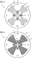
- FIG. 13 shows a front view of a second embodiment of a rectifier device 7. This embodiment differs from that in FIG Figures 3 and 4 illustrated embodiment only in that each of the Figures 3 and 4 recesses 25 shown a region of the carrier 15 is replaced, in which a plurality of recesses 25 are arranged.
- the shape of the cutouts 25 can, for example, advantageously be calculated with a topology optimization.
- FIG. 13 shows a front view of a third embodiment of a rectifier device 7.
- This embodiment differs from that in FIG Figures 3 and 4 illustrated embodiment only in that each of the Figures 3 and 4
- the recesses 25 shown are penetrated by a further lattice structure 45 of the carrier 15.
- the lattice structure 45 has struts with a thickness in the range from 0.5 mm to 3 mm and lattice spacings in the range from 1 mm to 5 mm. These parameters are determined, for example, in such a way that the carrier 15 has a maximum strength and rigidity with a minimum weight.
- FIG. 13 shows a front view of a fourth embodiment of a rectifier device 7.
- This embodiment differs from that in FIG Figures 3 and 4 illustrated embodiment only in that each of the Figures 3 and 4
- the recesses 25 shown are replaced by a porous region 47 of the carrier 15, in which a plurality of small recesses 25 are arranged.
- the porosity of the porous areas 47 can be produced by a design specification or by the targeted use of certain process parameters in a 3D printing process.
- the exemplary embodiments shown of a rectifier device 7 according to the invention can be modified in various ways to form further exemplary embodiments.
- the cooling channels 31 can have a different shape than that in FIG Figure 4 have cooling channels 31 shown, for example an elliptical or rectilinear shape.
- the latent heat storage volume 41 can also have a different shape than in FIG Figure 4 and / or be designed without the lattice structure 43.
- Particularly simple embodiments of a rectifier device according to the invention 7 have no latent heat storage volume 41 at all.
- the Figures 3 and 4 The exemplary embodiment shown can be modified in that the rectifier device 7 has a different number of electrical components 17, recesses 25, cooling channels 31, cooling structures 27 and / or latent heat storage volumes 41, and the exemplary embodiments shown in FIGS. 5 to 7 can also be modified accordingly .
- Rectifier devices 7 shown are for mounting on the end of a rotor shaft 9 as in the case of FIG Figure 2 shown embodiment of an exciter 1 designed.
- the carrier 15 is designed with a recess for the implementation of the rotor shaft 9.
- the carrier 15 is preferably manufactured with a 3D printing process, for example from a titanium or aluminum alloy or from another lightweight material.
- the cooling channels 31 and latent heat storage volumes 41 are each made with at least one opening through which they are then filled with the cooling fluid 32 or the phase change material 42. The openings are closed after filling.
- the geometric structure of the carrier 15 is calculated, for example, by a topology optimization with which a mass and / or a moment of inertia of the carrier 15 with respect to the axis of rotation 14 is minimized.
Landscapes
- Engineering & Computer Science (AREA)
- Power Engineering (AREA)
- Synchronous Machinery (AREA)
- Motor Or Generator Cooling System (AREA)
Priority Applications (2)
| Application Number | Priority Date | Filing Date | Title |
|---|---|---|---|
| EP19169549.3A EP3726708A1 (fr) | 2019-04-16 | 2019-04-16 | Dispositif redresseur, son procédé de fabrication et excitatrice |
| PCT/EP2020/054829 WO2020211996A1 (fr) | 2019-04-16 | 2020-02-25 | Dispositif redresseur, procédé de fabrication de celui-ci et machine d'excitation |
Applications Claiming Priority (1)
| Application Number | Priority Date | Filing Date | Title |
|---|---|---|---|
| EP19169549.3A EP3726708A1 (fr) | 2019-04-16 | 2019-04-16 | Dispositif redresseur, son procédé de fabrication et excitatrice |
Publications (1)
| Publication Number | Publication Date |
|---|---|
| EP3726708A1 true EP3726708A1 (fr) | 2020-10-21 |
Family
ID=66217786
Family Applications (1)
| Application Number | Title | Priority Date | Filing Date |
|---|---|---|---|
| EP19169549.3A Withdrawn EP3726708A1 (fr) | 2019-04-16 | 2019-04-16 | Dispositif redresseur, son procédé de fabrication et excitatrice |
Country Status (2)
| Country | Link |
|---|---|
| EP (1) | EP3726708A1 (fr) |
| WO (1) | WO2020211996A1 (fr) |
Citations (2)
| Publication number | Priority date | Publication date | Assignee | Title |
|---|---|---|---|---|
| EP1717536A1 (fr) * | 2005-04-25 | 2006-11-02 | Actron Technology Corporation | Procédé de fabrication d'une structure de dissipateur de chaleur pour un redresseur |
| WO2018130367A1 (fr) * | 2017-01-13 | 2018-07-19 | Siemens Aktiengesellschaft | Dispositif de refroidissement comprenant un caloduc et un accumulateur de chaleur latente, procédé de fabrication de celui-ci et circuit électronique |
-
2019
- 2019-04-16 EP EP19169549.3A patent/EP3726708A1/fr not_active Withdrawn
-
2020
- 2020-02-25 WO PCT/EP2020/054829 patent/WO2020211996A1/fr not_active Ceased
Patent Citations (2)
| Publication number | Priority date | Publication date | Assignee | Title |
|---|---|---|---|---|
| EP1717536A1 (fr) * | 2005-04-25 | 2006-11-02 | Actron Technology Corporation | Procédé de fabrication d'une structure de dissipateur de chaleur pour un redresseur |
| WO2018130367A1 (fr) * | 2017-01-13 | 2018-07-19 | Siemens Aktiengesellschaft | Dispositif de refroidissement comprenant un caloduc et un accumulateur de chaleur latente, procédé de fabrication de celui-ci et circuit électronique |
Non-Patent Citations (1)
| Title |
|---|
| ANONYMOUS: "Generatives Fertigungsverfahren - Wikipedia", 19 February 2017 (2017-02-19), Internet citation, pages 1 - 6, XP055404628, Retrieved from the Internet <URL:https://de.wikipedia.org/w/index.php?title=Generatives_Fertigungsverfahren&oldid=162809003> [retrieved on 20170907] * |
Also Published As
| Publication number | Publication date |
|---|---|
| WO2020211996A1 (fr) | 2020-10-22 |
Similar Documents
| Publication | Publication Date | Title |
|---|---|---|
| DE10124268B4 (de) | Generatorkühlung | |
| AT502587B1 (de) | Systeme, verfahren und einrichtungen für ein komposit-röntgentarget | |
| DE112016002202B4 (de) | Elektrische Rotationsmaschine | |
| DE102012021758B4 (de) | Rotor eines Permanentmagnet-Synchronmotors, Motor und Werkzeugmaschine | |
| DE2810222A1 (de) | Kuehlvorrichtung fuer elektrische maschinen | |
| DE102017214560B4 (de) | Mehrteilige Rotorwelle für eine elektrische Maschine | |
| DE102005034687B3 (de) | Drehkolbenstrahler | |
| WO2014090694A1 (fr) | Induit à cage d'écureuil fiable | |
| DE112013001368T5 (de) | Turbolader mit Axiallager zur Bereitstellung von kombinierten Zapfen- und Axiallager-Funktionen | |
| EP2862263A2 (fr) | Chemise de refroidissement | |
| DE102016218741A1 (de) | Elektrische Maschine mit verbesserter Kühlung | |
| DE102015204872A1 (de) | Käfigläufer für eine elektrische Asynchronmaschine mit einen Kurzschlussring stabilisierenden Zugankern | |
| DE2141581A1 (de) | Vorrichtung zur Energiespeicherung | |
| DE102016219588A1 (de) | Rotor für eine elektrische Maschine | |
| WO2014032868A2 (fr) | Rotor de machine électrique et machine électrique | |
| DE102020114691A1 (de) | Elektromechanischer Energiewandler mit Kühlung der Rotorwicklung | |
| EP3424135A1 (fr) | Moteur électrique, pompe à chaleur dotée dudit moteur électrique, procédé de production du moteur électrique et procédé pour faire fonctionner ledit moteur électrique | |
| WO2018202235A1 (fr) | Machine électrique avec dispositif de refroidissement | |
| DE102020204498A1 (de) | Bremssattel für eine Scheibenbremse für ein Fahrzeug und Verfahren zum Herstellen eines Bremssattels | |
| EP3726708A1 (fr) | Dispositif redresseur, son procédé de fabrication et excitatrice | |
| DE102024129046A1 (de) | Kuhlseparatoren fur einen gewickelten rotor | |
| WO2005099070A1 (fr) | Dispositif de refroidissement destine a une machine electrique pouvant etre refroidie au moyen d'un liquide de refroidissement | |
| DE202022104389U1 (de) | Effiziente Wärmeabfuhr über Gleitlager einer Drehanode | |
| EP3084927B1 (fr) | Rotor d'une machine électrique rotative | |
| WO2017076684A1 (fr) | Machine tournante et véhicule à moteur |
Legal Events
| Date | Code | Title | Description |
|---|---|---|---|
| PUAI | Public reference made under article 153(3) epc to a published international application that has entered the european phase |
Free format text: ORIGINAL CODE: 0009012 |
|
| STAA | Information on the status of an ep patent application or granted ep patent |
Free format text: STATUS: THE APPLICATION HAS BEEN PUBLISHED |
|
| AK | Designated contracting states |
Kind code of ref document: A1 Designated state(s): AL AT BE BG CH CY CZ DE DK EE ES FI FR GB GR HR HU IE IS IT LI LT LU LV MC MK MT NL NO PL PT RO RS SE SI SK SM TR |
|
| AX | Request for extension of the european patent |
Extension state: BA ME |
|
| STAA | Information on the status of an ep patent application or granted ep patent |
Free format text: STATUS: THE APPLICATION IS DEEMED TO BE WITHDRAWN |
|
| 18D | Application deemed to be withdrawn |
Effective date: 20210422 |