EP3727089B1 - Double paroi latérale de tiroir avec un bord inferieur arriere arrondi - Google Patents
Double paroi latérale de tiroir avec un bord inferieur arriere arrondi Download PDFInfo
- Publication number
- EP3727089B1 EP3727089B1 EP18826914.6A EP18826914A EP3727089B1 EP 3727089 B1 EP3727089 B1 EP 3727089B1 EP 18826914 A EP18826914 A EP 18826914A EP 3727089 B1 EP3727089 B1 EP 3727089B1
- Authority
- EP
- European Patent Office
- Prior art keywords
- wall
- drawer
- double
- walled
- sidewall
- Prior art date
- Legal status (The legal status is an assumption and is not a legal conclusion. Google has not performed a legal analysis and makes no representation as to the accuracy of the status listed.)
- Active
Links
Images



Classifications
-
- A—HUMAN NECESSITIES
- A47—FURNITURE; DOMESTIC ARTICLES OR APPLIANCES; COFFEE MILLS; SPICE MILLS; SUCTION CLEANERS IN GENERAL
- A47B—TABLES; DESKS; OFFICE FURNITURE; CABINETS; DRAWERS; GENERAL DETAILS OF FURNITURE
- A47B88/00—Drawers for tables, cabinets or like furniture; Guides for drawers
- A47B88/90—Constructional details of drawers
- A47B88/941—Drawers being constructed from two or more parts
-
- A—HUMAN NECESSITIES
- A47—FURNITURE; DOMESTIC ARTICLES OR APPLIANCES; COFFEE MILLS; SPICE MILLS; SUCTION CLEANERS IN GENERAL
- A47B—TABLES; DESKS; OFFICE FURNITURE; CABINETS; DRAWERS; GENERAL DETAILS OF FURNITURE
- A47B88/00—Drawers for tables, cabinets or like furniture; Guides for drawers
- A47B88/90—Constructional details of drawers
-
- A—HUMAN NECESSITIES
- A47—FURNITURE; DOMESTIC ARTICLES OR APPLIANCES; COFFEE MILLS; SPICE MILLS; SUCTION CLEANERS IN GENERAL
- A47B—TABLES; DESKS; OFFICE FURNITURE; CABINETS; DRAWERS; GENERAL DETAILS OF FURNITURE
- A47B88/00—Drawers for tables, cabinets or like furniture; Guides for drawers
- A47B88/40—Sliding drawers; Slides or guides therefor
- A47B88/402—Profiles or supporting structures for supporting single drawers
-
- A—HUMAN NECESSITIES
- A47—FURNITURE; DOMESTIC ARTICLES OR APPLIANCES; COFFEE MILLS; SPICE MILLS; SUCTION CLEANERS IN GENERAL
- A47B—TABLES; DESKS; OFFICE FURNITURE; CABINETS; DRAWERS; GENERAL DETAILS OF FURNITURE
- A47B88/00—Drawers for tables, cabinets or like furniture; Guides for drawers
- A47B88/50—Safety devices or the like for drawers
-
- A—HUMAN NECESSITIES
- A47—FURNITURE; DOMESTIC ARTICLES OR APPLIANCES; COFFEE MILLS; SPICE MILLS; SUCTION CLEANERS IN GENERAL
- A47B—TABLES; DESKS; OFFICE FURNITURE; CABINETS; DRAWERS; GENERAL DETAILS OF FURNITURE
- A47B88/00—Drawers for tables, cabinets or like furniture; Guides for drawers
- A47B88/90—Constructional details of drawers
- A47B88/906—Drawers being made of one piece of material, e.g. formed from folded sheet material or moulded
-
- A—HUMAN NECESSITIES
- A47—FURNITURE; DOMESTIC ARTICLES OR APPLIANCES; COFFEE MILLS; SPICE MILLS; SUCTION CLEANERS IN GENERAL
- A47B—TABLES; DESKS; OFFICE FURNITURE; CABINETS; DRAWERS; GENERAL DETAILS OF FURNITURE
- A47B88/00—Drawers for tables, cabinets or like furniture; Guides for drawers
- A47B88/90—Constructional details of drawers
- A47B88/944—Drawers characterised by the front panel
- A47B88/95—Drawers characterised by the front panel characterised by connection means for the front panel
-
- A—HUMAN NECESSITIES
- A47—FURNITURE; DOMESTIC ARTICLES OR APPLIANCES; COFFEE MILLS; SPICE MILLS; SUCTION CLEANERS IN GENERAL
- A47B—TABLES; DESKS; OFFICE FURNITURE; CABINETS; DRAWERS; GENERAL DETAILS OF FURNITURE
- A47B96/00—Details of cabinets, racks or shelf units not covered by a single one of groups A47B43/00 - A47B95/00; General details of furniture
- A47B96/20—Furniture panels or like furniture elements
- A47B96/205—Composite panels, comprising several elements joined together
- A47B96/206—Composite panels, comprising several elements joined together with laminates comprising planar, continuous or separate layers
-
- A—HUMAN NECESSITIES
- A47—FURNITURE; DOMESTIC ARTICLES OR APPLIANCES; COFFEE MILLS; SPICE MILLS; SUCTION CLEANERS IN GENERAL
- A47B—TABLES; DESKS; OFFICE FURNITURE; CABINETS; DRAWERS; GENERAL DETAILS OF FURNITURE
- A47B2210/00—General construction of drawers, guides and guide devices
- A47B2210/02—Drawers with hollow lateral walls in two parts
Definitions
- the invention relates to a double-walled drawer side wall with an outer wall and an inner wall connected thereto. Furthermore, the invention relates to a method for producing such a double-walled drawer side wall and to a drawer with such double-walled drawer side walls.
- Double-walled drawer side walls are already well known in the state of the art. These double-walled drawer side walls usually consist of a hat-shaped metal sheet, whereby the outer wall and the inner wall can be formed as one piece. However, it is also possible for these two walls to be connected to one another using known connection techniques. Overall, such double-walled drawer side walls have the advantage that functional parts can be accommodated inside, for example a connection device in the front area for detachable connection to a front wall holder that is pre-mounted on a front panel of the drawer. A so-called rear wall holder can be provided at the rear end, onto which the rear wall of the drawer can be snapped.
- the double-walled drawer side wall is typically hat-shaped, with the underside being able to be placed on a rail system directly or via a container rail connected to the outer and/or inner wall.
- a rail system directly or via a container rail connected to the outer and/or inner wall.
- Such rail systems typically have a body rail attached to the furniture body and a drawer rail that can be moved relative to it, in particular via rolling elements, and which can be firmly connected to the drawer during operation.
- a middle rail can also be arranged between these two rails in order to achieve a so-called full extension.
- the double-walled drawer side wall can have a profiled container rail running lengthways at its lower part, which is firmly connected to the double-walled drawer side wall.
- a container rail typically also has a web pointing towards the inside of the drawer, on which a drawer base can be placed.
- the area of the container rail which is recessed in the profile and essentially open at the bottom in a U-shape, serves to accommodate and connect to a drawer rail of a rail system. All of these Details and details can preferably also be provided in the double-walled drawer side wall according to the invention.
- a drawer with two such double-walled drawer side walls on the left and right, a drawer base, a rear back wall and a front front panel can typically be hung detachably in a rail system provided in the body and thus detachably connected.
- This means that the drawer can be easily inserted into the rail system in the furniture body and removed again, for example for cleaning purposes or during initial assembly.
- the problem is that when the drawer is removed, a support, such as a kitchen worktop, can be damaged, in particular scratched, by handling the drawer.
- Drawer side walls with a hollow profile are, for example, made of EP 1 775 225 A1 , from the US 5,292,190 A , from the WO 2017/186639 A1 , from the WO 2016/000002 A1 , from the DE 295 18 912 U1 , from the EP 0 702 916 A2 and from the WO 2017/106890 A1 known.
- the object of the invention is to create a double-walled drawer side wall with which the risk of damage when handling a drawer with such a double-walled drawer side wall is reduced. Furthermore, a method for producing such a drawer side wall and a drawer equipped with it are to be specified.
- the invention is based on the knowledge that the main risk of damaging a support, in particular the surface of a kitchen worktop, is due to lifting a drawer resting on it at the front, because then the rear lower end of the double-walled drawer side wall, which is normally designed with sharp edges, can scratch the support and thus damage it.
- the basic idea of the invention is to make this critical rear lower end of the outer wall less sharp-edged by rounding it off, thus minimizing the risk of damage.
- This rounding can either be formed in the material of the drawer side wall itself, but it is also possible according to a further variant of the invention that the rounding is formed on a separate edge protection part connected to the outer wall - preferably via a snap-in connection.
- This coating can be a powder coating or a varnish, for example.
- Other coatings are also conceivable and possible. It is important that these coatings are softer and smoother than the mostly metallic material of the outer wall, especially when applied to the front side of the rounded section, and the risk of scratches is further reduced.
- front and back refer to the direction in which the drawer is pulled out, with a front panel arranged at the front in the direction of pulling out, while a rear wall is provided on the rear side, which is at the back in the direction of pulling out.
- the two double-walled drawer side walls, which limit the interior of the drawer, run downwards in the direction of pulling out, and the entire drawer is then closed off by a drawer base.
- the Fig.1 shows a drawer, designated overall by 1, which can be pulled out of a furniture body 7 (not shown here) in the pull-out direction 2.
- the drawer 1 can be pushed back into a furniture body 7 in the opposite direction to the pull-out direction 2.
- the drawer base 3 of the drawer 1 is laterally delimited by the two double-walled drawer side walls 4 (outer wall 4a, inner wall 4b).
- a rear wall 5 is connected to these drawer side walls 4.
- a front panel 6 is provided, which can be detachably connected in a known manner via a detachable locking connection to the drawer side walls 4 or connecting devices not shown in detail therein.
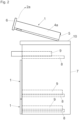
- the Fig.2 shows a schematic side view of a furniture body 7 with two inserted lower drawers 1.
- a body rail 8 connected to the furniture body 7 and a drawer rail 9 that can be moved relative to it are provided for the movable guidance of the drawers 1.
- a middle rail (not shown) can also be provided between these two rails 8, 9 in order to achieve full extension.
- the drawers 1 are detachably connected to this rail system 8, 9 so that the drawer 1 can be easily installed or removed for cleaning purposes.
- the drawer 1 In such a case, it is usual to place the drawer 1 on the worktop 10 or another support.
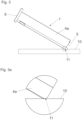
- the drawer 1 is often tilted upwards at the front in the direction of the arrow 2a, which, like the Figures 3 and 3a show, the rear lower end of the outer wall 4a of the drawer side wall 4 presses into the worktop 10. This poses the risk of damage to the same.
- the rear lower end of the outer wall 4a is provided with a rounding 11, which in this embodiment is formed directly by rounding the outer wall 4a.
- the rounding 11 reduces the sharp edges and thus the risk of damage to the worktop 10 or another support.
- the metal drawer side wall 4 is preferably coated, with the subsequent coating also extending to the front side 4e of the rounding 11.
- FIG.4 The view shown shows a drawer 1 with a double-walled drawer side wall 4 according to the invention from the inner bottom.
- the area B is in Fig. 4a shown enlarged.
- the drawer 1 has a drawer side wall 4, the outer wall 4a of which is flanged in the lower area along the longitudinal edge 12.
- the rounding 11 according to the invention is provided in this U-shaped flanged area.
- a container rail 13 is firmly connected to the drawer side wall 4.
- Fig.5 shows a schematic section along the line CC from the Figure 4 .
- the double-walled drawer side wall 4 with an outer wall 4a and an inner wall 4b, which are formed in one piece with each other and together form a hat-shaped profile (so-called frame hat).
- a container rail 13 is firmly connected to the double-walled drawer side wall 4, namely to both the outer wall 4a and the inner wall 4b.
- the connection 14 can be made, for example, by welding or gluing.
- the container rail 13 has a support web 13a for the drawer base 3 and is used for detachable connection to a schematically shown rail system consisting of drawer rail 9, middle rail and body rail 8.
- the enlarged illustration shown shows the rear lower end of the outer wall 4a.
- the rounding 11 is essentially circular in this embodiment, the radius of curvature R preferably being between 1 mm and 10 mm and preferably between 2 mm and 5 mm.
- the distance D of the rounding 11 from the imaginary intersection point S is at least 1 mm, preferably at least 2 mm, and at most 2 cm.
- a separate edge protection part 15 is provided, which can be made of plastic. It has the rounding 11.
- the edge protection part 15 is - like the Figures 7a and 7b show - can be plugged onto the outer wall 4a of the double-walled drawer side wall 4, wherein a small locking element in the interior of the receiving slot 17 of the edge protection part 15 engages in an opening 16 and holds the edge protection part 15 securely in position.
Landscapes
- Drawers Of Furniture (AREA)
- Cartons (AREA)
Claims (15)
- Paroi latérale de tiroir (4) à double paroi avec une paroi extérieure (4a) et une paroi intérieure (4b) se trouvant en liaison avec celle-ci, dans laquelle un arrondi (11) est prévu dans une vue de côté de la paroi latérale de tiroir (4) à l'extrémité inférieure arrière de la paroi extérieure (4a), dans laquelle l'arrondi (11) est prévu afin de minimiser un risque d'endommagement d'un appui, lorsqu'un tiroir comprenant la paroi latérale de tiroir (4) et reposant sur l'appui est relevé au niveau d'un côté frontal opposé à l'extrémité inférieure arrière de la paroi extérieure (4a), dans laquelle dans la zone inférieure, un rail de réceptacle (13) profilé en U par sections est agencé entre la paroi extérieure (4a) et la paroi intérieure (4b) et est relié fixement à celle-ci, dans laquelle le rail de réceptacle (13) présente une nervure d'appui (13a) tournée vers le côté intérieur de tiroir, sur laquelle un fond de tiroir (3) peut être placé.
- Paroi latérale de tiroir à double paroi selon la revendication 1, caractérisée en ce que l'arrondi (11) est formé sur la paroi extérieure (4a) même.
- Paroi latérale de tiroir à double paroi selon la revendication 2, caractérisée en ce que la paroi extérieure (4a) est rabattue au niveau d'une arête longitudinale (12) inférieure.
- Paroi latérale de tiroir à double paroi selon la revendication 3, caractérisée en ce que la paroi extérieure (4a) est repliée dans la zone de l'arête longitudinale (12) inférieure, vu en section transversale, sensiblement en forme de U, dans laquelle la section (4f) repliée s'étend au niveau du côté intérieur de la paroi extérieure (4a).
- Paroi latérale de tiroir à double paroi selon la revendication 3 ou 4, caractérisée en ce que la section (4f) repliée et la partie inférieure - s'étendant de préférence sensiblement parallèlement à celle-ci - de la paroi extérieure (4a) présentent à l'extrémité inférieure arrière de celles-ci sensiblement le même arrondi (11).
- Paroi latérale de tiroir à double paroi selon l'une quelconque des revendications 1 à 5, caractérisée en ce que la paroi extérieure (4a) et de préférence aussi la paroi intérieure (4b) sont pourvues d'un revêtement, dans laquelle ce revêtement est aussi prévu dans la zone du côté frontal (4e) - s'étendant de préférence sensiblement à angle droit par rapport à la surface extérieure contiguë de la paroi extérieure (4a) - de l'arrondi (11).
- Paroi latérale de tiroir à double paroi selon l'une quelconque des revendications 1 à 6, caractérisée en ce que l'arrondi (11) est courbé de manière convexe, par exemple sensiblement en forme d'arc de cercle.
- Paroi latérale de tiroir à double paroi selon la revendication 7, caractérisée en ce que le rayon de courbure (R) de l'arc de cercle est compris entre 1 mm et 10 mm, de préférence entre 2 mm et 5 mm.
- Paroi latérale de tiroir à double paroi selon l'une quelconque des revendications 1 à 8, caractérisée en ce que la distance (D) de l'arrondi (11) par rapport à l'intersection (S) de l'arête longitudinale (4c) inférieure prolongée imaginaire de la paroi extérieure (4a) avec l'arête verticale (4d) arrière prolongée imaginaire de la paroi extérieure (4a) s'élève au moins à 1 mm, de préférence au moins à 2 mm, et s'élève au plus à 2 cm.
- Paroi latérale de tiroir à double paroi selon la revendication 1 et l'une quelconque des revendications 6 à 9, caractérisée en ce que l'arrondi (11) est réalisé au niveau d'une partie de protection d'arête (15) séparée, reliée avec la paroi extérieure (4a) - de préférence par le biais d'une liaison d'encliquetage.
- Paroi latérale de tiroir à double paroi selon l'une quelconque des revendications 1 à 10, caractérisée en ce que l'arrondi (11) s'étend de l'extrémité arrière de l'arête longitudinale (4c) inférieure droite de la paroi extérieure (4a) jusqu'à l'arête inférieure de l'arête verticale (4d) arrière droite de la paroi extérieure (4a).
- Procédé de fabrication d'une paroi latérale de tiroir à double paroi selon l'une quelconque des revendications 1 à 11, caractérisé par la réalisation d'un arrondi (11) à l'extrémité inférieure arrière de la paroi extérieure (4a) et le revêtement suivant de la paroi latérale de tiroir (4) avec son arrondi (11).
- Procédé de fabrication d'une paroi latérale de tiroir à double paroi selon la revendication 12, caractérisé par la formation de la paroi latérale de tiroir (4), éventuellement le revêtement de celle-ci, et le montage suivant d'une partie de protection d'arête (15) arrondie à l'extrémité inférieure arrière de la paroi extérieure (4a).
- Tiroir (1) avec deux parois latérales de tiroir (4) à double paroi opposées selon l'une quelconque des revendications 1 à 11.
- Tiroir (1) selon la revendication 14, caractérisé par un panneau frontal (6) avant, une paroi de fond arrière (5) et un fond de tiroir (3) qui sont reliés - de préférence de manière amovible - respectivement aux parois latérales de tiroir (4).
Applications Claiming Priority (2)
| Application Number | Priority Date | Filing Date | Title |
|---|---|---|---|
| ATA51046/2017A AT520804B1 (de) | 2017-12-19 | 2017-12-19 | Doppelwandige Schubladenseitenwand |
| PCT/AT2018/060290 WO2019118997A1 (fr) | 2017-12-19 | 2018-12-07 | Paroi latérale de tiroir à double paroi |
Publications (2)
| Publication Number | Publication Date |
|---|---|
| EP3727089A1 EP3727089A1 (fr) | 2020-10-28 |
| EP3727089B1 true EP3727089B1 (fr) | 2024-06-12 |
Family
ID=64901241
Family Applications (1)
| Application Number | Title | Priority Date | Filing Date |
|---|---|---|---|
| EP18826914.6A Active EP3727089B1 (fr) | 2017-12-19 | 2018-12-07 | Double paroi latérale de tiroir avec un bord inferieur arriere arrondi |
Country Status (9)
| Country | Link |
|---|---|
| US (1) | US20200305601A1 (fr) |
| EP (1) | EP3727089B1 (fr) |
| JP (1) | JP7114713B2 (fr) |
| CN (1) | CN111511250A (fr) |
| AT (1) | AT520804B1 (fr) |
| ES (1) | ES2985954T3 (fr) |
| MY (1) | MY205107A (fr) |
| TW (1) | TWI682742B (fr) |
| WO (1) | WO2019118997A1 (fr) |
Families Citing this family (2)
| Publication number | Priority date | Publication date | Assignee | Title |
|---|---|---|---|---|
| AT524493B1 (de) | 2020-12-02 | 2024-10-15 | Blum Gmbh Julius | Verfahren zur manuellen und/oder maschinellen Herstellung einer doppelwandigen Schubladenzarge |
| DE102023130076A1 (de) | 2023-10-31 | 2025-04-30 | Paul Hettich Gmbh & Co. Kg | Schubkasten |
Citations (1)
| Publication number | Priority date | Publication date | Assignee | Title |
|---|---|---|---|---|
| WO2017106890A1 (fr) * | 2015-12-22 | 2017-06-29 | Julius Blum Gmbh | Paroi latérale de tiroir |
Family Cites Families (24)
| Publication number | Priority date | Publication date | Assignee | Title |
|---|---|---|---|---|
| JPS55147462U (fr) * | 1979-04-11 | 1980-10-23 | ||
| JPS56115944U (fr) * | 1980-02-05 | 1981-09-05 | ||
| JPS60121829U (ja) * | 1984-01-27 | 1985-08-16 | 株式会社 伊藤喜工作所 | 袖抽斗キヤビネツトの縁保護装置 |
| DE4004332A1 (de) * | 1990-02-13 | 1991-08-14 | Lautenschlaeger Kg Karl | Ausgeschaeumtes schubladenwand-hohlkammerprofil und verfahren zu seiner herstellung |
| DE4433577A1 (de) * | 1994-09-21 | 1996-03-28 | Hettich Paul Gmbh & Co | Möbelauszugsteil |
| AT404219B (de) * | 1995-01-19 | 1998-09-25 | Blum Gmbh Julius | Schublade |
| DE29518912U1 (de) * | 1995-11-29 | 1996-01-18 | BBP-Kunststoffwerk Marbach Baier GmbH und Co KG, 71672 Marbach | Schublade |
| AT409072B (de) * | 1998-06-24 | 2002-05-27 | Blum Gmbh Julius | Schubladenzarge |
| GB0204963D0 (en) * | 2002-03-02 | 2002-04-17 | Durrant Sam A M | Improvements in corner protectors |
| CN2557902Y (zh) * | 2002-07-20 | 2003-06-25 | 海尔集团公司 | 冷柜抽屉 |
| DE202005008286U1 (de) * | 2005-05-27 | 2006-10-05 | Paul Hettich Gmbh & Co. Kg | Schubkasten |
| ES2272190B1 (es) * | 2005-10-11 | 2008-02-16 | Miguel Angel Rioja Calvo | Cajon metalico para mobiliario. |
| CN201328549Y (zh) * | 2009-01-08 | 2009-10-21 | 河南省花城办公家具有限公司 | 一种钢制办公家具门、抽屉或柜体的面板体 |
| AT510016B1 (de) * | 2010-11-23 | 2012-01-15 | Blum Gmbh Julius | Schubladenseitenwand mit einer innenwand und einer aussenwand |
| AT512383B1 (de) * | 2011-12-22 | 2016-06-15 | Blum Gmbh Julius | Doppelwandige schubladenzarge mit einer innenwand und einer aussenwand |
| CN102711401B (zh) * | 2012-02-24 | 2018-07-27 | 海尔集团公司 | 一种用于家用电器的抽拉旋转抽屉组合体 |
| DE202013011429U1 (de) * | 2013-12-20 | 2015-03-23 | Grass Gmbh | Möbelschublade und Schubladenwandelement für eine Schublade |
| DE202013011426U1 (de) * | 2013-12-20 | 2015-03-23 | Grass Gmbh | Schubladenwandeelement |
| AT515997B1 (de) * | 2014-07-04 | 2017-11-15 | Blum Gmbh Julius | Anordnung mit Schubladenseitenwand und Halteteil |
| CN204519712U (zh) * | 2015-04-08 | 2015-08-05 | 浙江黄岩侨丰塑料制品厂 | 搭接式化妆品收纳盒 |
| CN204519713U (zh) * | 2015-04-08 | 2015-08-05 | 浙江黄岩侨丰塑料制品厂 | 化妆品收纳盒 |
| CN104819618B (zh) * | 2015-05-07 | 2017-10-27 | 湖北美的电冰箱有限公司 | 用于制冷设备的抽屉组件及制冷设备 |
| DE102016107816A1 (de) * | 2016-04-27 | 2017-11-02 | Paul Hettich Gmbh & Co. Kg | Seitenzarge für einen Schubkasten |
| CN206453550U (zh) * | 2016-08-26 | 2017-09-01 | 唐山曹妃甸区健通纸制品厂 | 一种物品用边角保护套结构 |
-
2017
- 2017-12-19 AT ATA51046/2017A patent/AT520804B1/de active
-
2018
- 2018-12-07 ES ES18826914T patent/ES2985954T3/es active Active
- 2018-12-07 CN CN201880082187.0A patent/CN111511250A/zh active Pending
- 2018-12-07 MY MYPI2020002944A patent/MY205107A/en unknown
- 2018-12-07 JP JP2020533671A patent/JP7114713B2/ja active Active
- 2018-12-07 WO PCT/AT2018/060290 patent/WO2019118997A1/fr not_active Ceased
- 2018-12-07 EP EP18826914.6A patent/EP3727089B1/fr active Active
- 2018-12-13 TW TW107144933A patent/TWI682742B/zh active
-
2020
- 2020-06-16 US US16/902,445 patent/US20200305601A1/en not_active Abandoned
Patent Citations (1)
| Publication number | Priority date | Publication date | Assignee | Title |
|---|---|---|---|---|
| WO2017106890A1 (fr) * | 2015-12-22 | 2017-06-29 | Julius Blum Gmbh | Paroi latérale de tiroir |
Also Published As
| Publication number | Publication date |
|---|---|
| EP3727089A1 (fr) | 2020-10-28 |
| WO2019118997A1 (fr) | 2019-06-27 |
| AT520804A1 (de) | 2019-07-15 |
| JP7114713B2 (ja) | 2022-08-08 |
| JP2021506446A (ja) | 2021-02-22 |
| MY205107A (en) | 2024-10-02 |
| CN111511250A (zh) | 2020-08-07 |
| US20200305601A1 (en) | 2020-10-01 |
| TWI682742B (zh) | 2020-01-21 |
| TW201927214A (zh) | 2019-07-16 |
| ES2985954T3 (es) | 2024-11-07 |
| AT520804B1 (de) | 2023-04-15 |
Similar Documents
| Publication | Publication Date | Title |
|---|---|---|
| EP2765886B1 (fr) | Dispositif de stockage d'ustensiles | |
| AT512934B1 (de) | Schubladenausziehführung | |
| AT511683B1 (de) | Schublade | |
| WO2011094772A1 (fr) | Système de tiroir | |
| EP1027844A2 (fr) | Tiroir avec garniture de barette de tiroir | |
| EP3727089B1 (fr) | Double paroi latérale de tiroir avec un bord inferieur arriere arrondi | |
| WO2011094771A1 (fr) | Récipient tiroir | |
| EP2844108B1 (fr) | Dispositif de retenue pour un élément support d'une armoire telle qu'un réfrigérateur, un congélateur ou armoire pour conserver du vin | |
| EP1573258A1 (fr) | Support destin un appareil frigorifique | |
| DE102010062780B4 (de) | Geschirrspülmaschine, insbesondere Haushaltsgeschirrspülmaschine | |
| DE10022084C2 (de) | Laufschiene für Schubkästen | |
| DE3537335C2 (fr) | ||
| DE3221926C2 (de) | Auszieheinrichtung für einen mit einem Möbelkorpus versehenen Schrank | |
| DE20215552U1 (de) | Träger für ein Regal | |
| EP1808104B1 (fr) | Utilisation d'un support présentoir pour la présentation incliné d'un object sur une grille | |
| AT396731B (de) | Schublade | |
| AT393350B (de) | Schubladenauszug | |
| AT393782B (de) | Ausziehfuehrung, insbesondere unterbodenausziehfuehrung, fuer schubkaesten, schubladen, fachboeden od. dgl. | |
| EP2640225B1 (fr) | Rail de support pour un fond de tiroir | |
| DE9104837U1 (de) | Rahmenstrebe für einen ausziehbaren Hängeregistraturrahmen | |
| DE20207764U1 (de) | Führungselement | |
| EP1145666A1 (fr) | Etagère en particulier pour des bibliothèques | |
| DE202026100237U1 (de) | Schubkasten | |
| DE102013210015A1 (de) | Führungsschiene für eine Geschirrspülmaschine | |
| EP1030118A1 (fr) | Support émaillé insérable |
Legal Events
| Date | Code | Title | Description |
|---|---|---|---|
| STAA | Information on the status of an ep patent application or granted ep patent |
Free format text: STATUS: UNKNOWN |
|
| STAA | Information on the status of an ep patent application or granted ep patent |
Free format text: STATUS: THE INTERNATIONAL PUBLICATION HAS BEEN MADE |
|
| PUAI | Public reference made under article 153(3) epc to a published international application that has entered the european phase |
Free format text: ORIGINAL CODE: 0009012 |
|
| STAA | Information on the status of an ep patent application or granted ep patent |
Free format text: STATUS: REQUEST FOR EXAMINATION WAS MADE |
|
| 17P | Request for examination filed |
Effective date: 20200717 |
|
| AK | Designated contracting states |
Kind code of ref document: A1 Designated state(s): AL AT BE BG CH CY CZ DE DK EE ES FI FR GB GR HR HU IE IS IT LI LT LU LV MC MK MT NL NO PL PT RO RS SE SI SK SM TR |
|
| AX | Request for extension of the european patent |
Extension state: BA ME |
|
| STAA | Information on the status of an ep patent application or granted ep patent |
Free format text: STATUS: EXAMINATION IS IN PROGRESS |
|
| DAV | Request for validation of the european patent (deleted) | ||
| DAX | Request for extension of the european patent (deleted) | ||
| 17Q | First examination report despatched |
Effective date: 20210329 |
|
| P01 | Opt-out of the competence of the unified patent court (upc) registered |
Effective date: 20230523 |
|
| GRAP | Despatch of communication of intention to grant a patent |
Free format text: ORIGINAL CODE: EPIDOSNIGR1 |
|
| STAA | Information on the status of an ep patent application or granted ep patent |
Free format text: STATUS: GRANT OF PATENT IS INTENDED |
|
| INTG | Intention to grant announced |
Effective date: 20240327 |
|
| GRAS | Grant fee paid |
Free format text: ORIGINAL CODE: EPIDOSNIGR3 |
|
| GRAA | (expected) grant |
Free format text: ORIGINAL CODE: 0009210 |
|
| STAA | Information on the status of an ep patent application or granted ep patent |
Free format text: STATUS: THE PATENT HAS BEEN GRANTED |
|
| AK | Designated contracting states |
Kind code of ref document: B1 Designated state(s): AL AT BE BG CH CY CZ DE DK EE ES FI FR GB GR HR HU IE IS IT LI LT LU LV MC MK MT NL NO PL PT RO RS SE SI SK SM TR |
|
| REG | Reference to a national code |
Ref country code: GB Ref legal event code: FG4D Free format text: NOT ENGLISH |
|
| REG | Reference to a national code |
Ref country code: CH Ref legal event code: EP |
|
| REG | Reference to a national code |
Ref country code: DE Ref legal event code: R096 Ref document number: 502018014741 Country of ref document: DE |
|
| REG | Reference to a national code |
Ref country code: IE Ref legal event code: FG4D Free format text: LANGUAGE OF EP DOCUMENT: GERMAN |
|
| PG25 | Lapsed in a contracting state [announced via postgrant information from national office to epo] |
Ref country code: BG Free format text: LAPSE BECAUSE OF FAILURE TO SUBMIT A TRANSLATION OF THE DESCRIPTION OR TO PAY THE FEE WITHIN THE PRESCRIBED TIME-LIMIT Effective date: 20240612 |
|
| PG25 | Lapsed in a contracting state [announced via postgrant information from national office to epo] |
Ref country code: FI Free format text: LAPSE BECAUSE OF FAILURE TO SUBMIT A TRANSLATION OF THE DESCRIPTION OR TO PAY THE FEE WITHIN THE PRESCRIBED TIME-LIMIT Effective date: 20240612 Ref country code: HR Free format text: LAPSE BECAUSE OF FAILURE TO SUBMIT A TRANSLATION OF THE DESCRIPTION OR TO PAY THE FEE WITHIN THE PRESCRIBED TIME-LIMIT Effective date: 20240612 |
|
| REG | Reference to a national code |
Ref country code: LT Ref legal event code: MG9D |
|
| PG25 | Lapsed in a contracting state [announced via postgrant information from national office to epo] |
Ref country code: GR Free format text: LAPSE BECAUSE OF FAILURE TO SUBMIT A TRANSLATION OF THE DESCRIPTION OR TO PAY THE FEE WITHIN THE PRESCRIBED TIME-LIMIT Effective date: 20240913 |
|
| REG | Reference to a national code |
Ref country code: NL Ref legal event code: MP Effective date: 20240612 |
|
| PG25 | Lapsed in a contracting state [announced via postgrant information from national office to epo] |
Ref country code: LV Free format text: LAPSE BECAUSE OF FAILURE TO SUBMIT A TRANSLATION OF THE DESCRIPTION OR TO PAY THE FEE WITHIN THE PRESCRIBED TIME-LIMIT Effective date: 20240612 |
|
| PG25 | Lapsed in a contracting state [announced via postgrant information from national office to epo] |
Ref country code: NO Free format text: LAPSE BECAUSE OF FAILURE TO SUBMIT A TRANSLATION OF THE DESCRIPTION OR TO PAY THE FEE WITHIN THE PRESCRIBED TIME-LIMIT Effective date: 20240912 Ref country code: LV Free format text: LAPSE BECAUSE OF FAILURE TO SUBMIT A TRANSLATION OF THE DESCRIPTION OR TO PAY THE FEE WITHIN THE PRESCRIBED TIME-LIMIT Effective date: 20240612 Ref country code: HR Free format text: LAPSE BECAUSE OF FAILURE TO SUBMIT A TRANSLATION OF THE DESCRIPTION OR TO PAY THE FEE WITHIN THE PRESCRIBED TIME-LIMIT Effective date: 20240612 Ref country code: GR Free format text: LAPSE BECAUSE OF FAILURE TO SUBMIT A TRANSLATION OF THE DESCRIPTION OR TO PAY THE FEE WITHIN THE PRESCRIBED TIME-LIMIT Effective date: 20240913 Ref country code: FI Free format text: LAPSE BECAUSE OF FAILURE TO SUBMIT A TRANSLATION OF THE DESCRIPTION OR TO PAY THE FEE WITHIN THE PRESCRIBED TIME-LIMIT Effective date: 20240612 Ref country code: BG Free format text: LAPSE BECAUSE OF FAILURE TO SUBMIT A TRANSLATION OF THE DESCRIPTION OR TO PAY THE FEE WITHIN THE PRESCRIBED TIME-LIMIT Effective date: 20240612 Ref country code: RS Free format text: LAPSE BECAUSE OF FAILURE TO SUBMIT A TRANSLATION OF THE DESCRIPTION OR TO PAY THE FEE WITHIN THE PRESCRIBED TIME-LIMIT Effective date: 20240912 |
|
| REG | Reference to a national code |
Ref country code: ES Ref legal event code: FG2A Ref document number: 2985954 Country of ref document: ES Kind code of ref document: T3 Effective date: 20241107 |
|
| PG25 | Lapsed in a contracting state [announced via postgrant information from national office to epo] |
Ref country code: NL Free format text: LAPSE BECAUSE OF FAILURE TO SUBMIT A TRANSLATION OF THE DESCRIPTION OR TO PAY THE FEE WITHIN THE PRESCRIBED TIME-LIMIT Effective date: 20240612 |
|
| PG25 | Lapsed in a contracting state [announced via postgrant information from national office to epo] |
Ref country code: NL Free format text: LAPSE BECAUSE OF FAILURE TO SUBMIT A TRANSLATION OF THE DESCRIPTION OR TO PAY THE FEE WITHIN THE PRESCRIBED TIME-LIMIT Effective date: 20240612 |
|
| PG25 | Lapsed in a contracting state [announced via postgrant information from national office to epo] |
Ref country code: PT Free format text: LAPSE BECAUSE OF FAILURE TO SUBMIT A TRANSLATION OF THE DESCRIPTION OR TO PAY THE FEE WITHIN THE PRESCRIBED TIME-LIMIT Effective date: 20241014 |
|
| PG25 | Lapsed in a contracting state [announced via postgrant information from national office to epo] |
Ref country code: PT Free format text: LAPSE BECAUSE OF FAILURE TO SUBMIT A TRANSLATION OF THE DESCRIPTION OR TO PAY THE FEE WITHIN THE PRESCRIBED TIME-LIMIT Effective date: 20241014 |
|
| PG25 | Lapsed in a contracting state [announced via postgrant information from national office to epo] |
Ref country code: PL Free format text: LAPSE BECAUSE OF FAILURE TO SUBMIT A TRANSLATION OF THE DESCRIPTION OR TO PAY THE FEE WITHIN THE PRESCRIBED TIME-LIMIT Effective date: 20240612 |
|
| PG25 | Lapsed in a contracting state [announced via postgrant information from national office to epo] |
Ref country code: EE Free format text: LAPSE BECAUSE OF FAILURE TO SUBMIT A TRANSLATION OF THE DESCRIPTION OR TO PAY THE FEE WITHIN THE PRESCRIBED TIME-LIMIT Effective date: 20240612 |
|
| PG25 | Lapsed in a contracting state [announced via postgrant information from national office to epo] |
Ref country code: IS Free format text: LAPSE BECAUSE OF FAILURE TO SUBMIT A TRANSLATION OF THE DESCRIPTION OR TO PAY THE FEE WITHIN THE PRESCRIBED TIME-LIMIT Effective date: 20241012 |
|
| PG25 | Lapsed in a contracting state [announced via postgrant information from national office to epo] |
Ref country code: CZ Free format text: LAPSE BECAUSE OF FAILURE TO SUBMIT A TRANSLATION OF THE DESCRIPTION OR TO PAY THE FEE WITHIN THE PRESCRIBED TIME-LIMIT Effective date: 20240612 |
|
| PG25 | Lapsed in a contracting state [announced via postgrant information from national office to epo] |
Ref country code: SK Free format text: LAPSE BECAUSE OF FAILURE TO SUBMIT A TRANSLATION OF THE DESCRIPTION OR TO PAY THE FEE WITHIN THE PRESCRIBED TIME-LIMIT Effective date: 20240612 Ref country code: RO Free format text: LAPSE BECAUSE OF FAILURE TO SUBMIT A TRANSLATION OF THE DESCRIPTION OR TO PAY THE FEE WITHIN THE PRESCRIBED TIME-LIMIT Effective date: 20240612 |
|
| PG25 | Lapsed in a contracting state [announced via postgrant information from national office to epo] |
Ref country code: SM Free format text: LAPSE BECAUSE OF FAILURE TO SUBMIT A TRANSLATION OF THE DESCRIPTION OR TO PAY THE FEE WITHIN THE PRESCRIBED TIME-LIMIT Effective date: 20240612 |
|
| PG25 | Lapsed in a contracting state [announced via postgrant information from national office to epo] |
Ref country code: SM Free format text: LAPSE BECAUSE OF FAILURE TO SUBMIT A TRANSLATION OF THE DESCRIPTION OR TO PAY THE FEE WITHIN THE PRESCRIBED TIME-LIMIT Effective date: 20240612 Ref country code: SK Free format text: LAPSE BECAUSE OF FAILURE TO SUBMIT A TRANSLATION OF THE DESCRIPTION OR TO PAY THE FEE WITHIN THE PRESCRIBED TIME-LIMIT Effective date: 20240612 Ref country code: RO Free format text: LAPSE BECAUSE OF FAILURE TO SUBMIT A TRANSLATION OF THE DESCRIPTION OR TO PAY THE FEE WITHIN THE PRESCRIBED TIME-LIMIT Effective date: 20240612 Ref country code: PL Free format text: LAPSE BECAUSE OF FAILURE TO SUBMIT A TRANSLATION OF THE DESCRIPTION OR TO PAY THE FEE WITHIN THE PRESCRIBED TIME-LIMIT Effective date: 20240612 Ref country code: IS Free format text: LAPSE BECAUSE OF FAILURE TO SUBMIT A TRANSLATION OF THE DESCRIPTION OR TO PAY THE FEE WITHIN THE PRESCRIBED TIME-LIMIT Effective date: 20241012 Ref country code: EE Free format text: LAPSE BECAUSE OF FAILURE TO SUBMIT A TRANSLATION OF THE DESCRIPTION OR TO PAY THE FEE WITHIN THE PRESCRIBED TIME-LIMIT Effective date: 20240612 Ref country code: CZ Free format text: LAPSE BECAUSE OF FAILURE TO SUBMIT A TRANSLATION OF THE DESCRIPTION OR TO PAY THE FEE WITHIN THE PRESCRIBED TIME-LIMIT Effective date: 20240612 |
|
| REG | Reference to a national code |
Ref country code: DE Ref legal event code: R097 Ref document number: 502018014741 Country of ref document: DE |
|
| PG25 | Lapsed in a contracting state [announced via postgrant information from national office to epo] |
Ref country code: DK Free format text: LAPSE BECAUSE OF FAILURE TO SUBMIT A TRANSLATION OF THE DESCRIPTION OR TO PAY THE FEE WITHIN THE PRESCRIBED TIME-LIMIT Effective date: 20240612 |
|
| PLBE | No opposition filed within time limit |
Free format text: ORIGINAL CODE: 0009261 |
|
| STAA | Information on the status of an ep patent application or granted ep patent |
Free format text: STATUS: NO OPPOSITION FILED WITHIN TIME LIMIT |
|
| 26N | No opposition filed |
Effective date: 20250313 |
|
| PG25 | Lapsed in a contracting state [announced via postgrant information from national office to epo] |
Ref country code: MC Free format text: LAPSE BECAUSE OF FAILURE TO SUBMIT A TRANSLATION OF THE DESCRIPTION OR TO PAY THE FEE WITHIN THE PRESCRIBED TIME-LIMIT Effective date: 20240612 |
|
| REG | Reference to a national code |
Ref country code: CH Ref legal event code: PL |
|
| PG25 | Lapsed in a contracting state [announced via postgrant information from national office to epo] |
Ref country code: LU Free format text: LAPSE BECAUSE OF NON-PAYMENT OF DUE FEES Effective date: 20241207 |
|
| GBPC | Gb: european patent ceased through non-payment of renewal fee |
Effective date: 20241207 |
|
| PG25 | Lapsed in a contracting state [announced via postgrant information from national office to epo] |
Ref country code: SE Free format text: LAPSE BECAUSE OF FAILURE TO SUBMIT A TRANSLATION OF THE DESCRIPTION OR TO PAY THE FEE WITHIN THE PRESCRIBED TIME-LIMIT Effective date: 20240612 |
|
| REG | Reference to a national code |
Ref country code: BE Ref legal event code: MM Effective date: 20241231 |
|
| PG25 | Lapsed in a contracting state [announced via postgrant information from national office to epo] |
Ref country code: GB Free format text: LAPSE BECAUSE OF NON-PAYMENT OF DUE FEES Effective date: 20241207 Ref country code: BE Free format text: LAPSE BECAUSE OF NON-PAYMENT OF DUE FEES Effective date: 20241231 |
|
| PG25 | Lapsed in a contracting state [announced via postgrant information from national office to epo] |
Ref country code: FR Free format text: LAPSE BECAUSE OF NON-PAYMENT OF DUE FEES Effective date: 20241231 |
|
| PG25 | Lapsed in a contracting state [announced via postgrant information from national office to epo] |
Ref country code: CH Free format text: LAPSE BECAUSE OF NON-PAYMENT OF DUE FEES Effective date: 20241231 |
|
| PG25 | Lapsed in a contracting state [announced via postgrant information from national office to epo] |
Ref country code: IE Free format text: LAPSE BECAUSE OF NON-PAYMENT OF DUE FEES Effective date: 20241207 |
|
| PGFP | Annual fee paid to national office [announced via postgrant information from national office to epo] |
Ref country code: AT Payment date: 20251223 Year of fee payment: 8 |
|
| PGFP | Annual fee paid to national office [announced via postgrant information from national office to epo] |
Ref country code: IT Payment date: 20251218 Year of fee payment: 8 |
|
| PGFP | Annual fee paid to national office [announced via postgrant information from national office to epo] |
Ref country code: TR Payment date: 20251118 Year of fee payment: 8 |
|
| PG25 | Lapsed in a contracting state [announced via postgrant information from national office to epo] |
Ref country code: CY Free format text: LAPSE BECAUSE OF FAILURE TO SUBMIT A TRANSLATION OF THE DESCRIPTION OR TO PAY THE FEE WITHIN THE PRESCRIBED TIME-LIMIT; INVALID AB INITIO Effective date: 20181207 |
|
| PGFP | Annual fee paid to national office [announced via postgrant information from national office to epo] |
Ref country code: ES Payment date: 20260122 Year of fee payment: 8 |
|
| PGFP | Annual fee paid to national office [announced via postgrant information from national office to epo] |
Ref country code: DE Payment date: 20251229 Year of fee payment: 8 |