EP3727730B1 - Verfahren zur herstellung eines schneidabschnittes für eine bohrkrone - Google Patents
Verfahren zur herstellung eines schneidabschnittes für eine bohrkrone Download PDFInfo
- Publication number
- EP3727730B1 EP3727730B1 EP18814959.5A EP18814959A EP3727730B1 EP 3727730 B1 EP3727730 B1 EP 3727730B1 EP 18814959 A EP18814959 A EP 18814959A EP 3727730 B1 EP3727730 B1 EP 3727730B1
- Authority
- EP
- European Patent Office
- Prior art keywords
- sheet metal
- metal part
- tubular element
- cutting section
- slot
- Prior art date
- Legal status (The legal status is an assumption and is not a legal conclusion. Google has not performed a legal analysis and makes no representation as to the accuracy of the status listed.)
- Active
Links
Images




Classifications
-
- B—PERFORMING OPERATIONS; TRANSPORTING
- B23—MACHINE TOOLS; METAL-WORKING NOT OTHERWISE PROVIDED FOR
- B23P—METAL-WORKING NOT OTHERWISE PROVIDED FOR; COMBINED OPERATIONS; UNIVERSAL MACHINE TOOLS
- B23P15/00—Making specific metal objects by operations not covered by a single other subclass or a group in this subclass
- B23P15/28—Making specific metal objects by operations not covered by a single other subclass or a group in this subclass cutting tools
-
- B—PERFORMING OPERATIONS; TRANSPORTING
- B21—MECHANICAL METAL-WORKING WITHOUT ESSENTIALLY REMOVING MATERIAL; PUNCHING METAL
- B21D—WORKING OR PROCESSING OF SHEET METAL OR METAL TUBES, RODS OR PROFILES WITHOUT ESSENTIALLY REMOVING MATERIAL; PUNCHING METAL
- B21D39/00—Application of procedures in order to connect objects or parts, e.g. coating with sheet metal otherwise than by plating; Tube expanders
- B21D39/04—Application of procedures in order to connect objects or parts, e.g. coating with sheet metal otherwise than by plating; Tube expanders of tubes with tubes; of tubes with rods
-
- B—PERFORMING OPERATIONS; TRANSPORTING
- B23—MACHINE TOOLS; METAL-WORKING NOT OTHERWISE PROVIDED FOR
- B23B—TURNING; BORING
- B23B51/00—Tools for drilling machines
- B23B51/04—Drills for trepanning
-
- B—PERFORMING OPERATIONS; TRANSPORTING
- B28—WORKING CEMENT, CLAY, OR STONE
- B28D—WORKING STONE OR STONE-LIKE MATERIALS
- B28D1/00—Working stone or stone-like materials, e.g. brick, concrete or glass, not provided for elsewhere; Machines, devices, tools therefor
- B28D1/02—Working stone or stone-like materials, e.g. brick, concrete or glass, not provided for elsewhere; Machines, devices, tools therefor by sawing
- B28D1/04—Working stone or stone-like materials, e.g. brick, concrete or glass, not provided for elsewhere; Machines, devices, tools therefor by sawing with circular or cylindrical saw-blades or saw-discs
- B28D1/041—Working stone or stone-like materials, e.g. brick, concrete or glass, not provided for elsewhere; Machines, devices, tools therefor by sawing with circular or cylindrical saw-blades or saw-discs with cylinder saws, e.g. trepanning; saw cylinders, e.g. having their cutting rim equipped with abrasive particles
Definitions
- the present invention relates to a method for manufacturing a cutting section for a drill bit.
- WO 2014/096359 A1 discloses a cutting section for a drill bit which can be connected to a drill shaft section of the drill bit via a releasable connecting device.
- the releasable connecting device is designed as a combined plug-in-turn connection.
- Plug-in-turn connection refers to releasable connections between a first and second connecting element which form a plug connection in one direction and are additionally connected via a rotary connection.
- the cutting section comprises one or more drilling segments, a ring section, an outer plug-in element and an annular stop shoulder at the transition from the ring section to the outer plug-in element.
- Cutting sections that can be connected with a combined plug-and-turn connection are sold under the product name "Hilti DD X-CM".
- the "Hilti DD X-CM” cutting sections comprise several drilling segments, a ring section and an outer plug-in element, with an annular stop shoulder for power transmission at the transition from the ring section to the outer plug-in element. The torque is transmitted with the help of pin elements that interact with slot-shaped recesses in the outer plug-in element.
- the "Hilti DD X-CM” cutting sections are made from a closed tubular element. The annular stop shoulder is produced by turning and the slot-shaped recesses are produced by milling.
- the object of the present invention is, in a method for producing a cutting section for a drill bit, to reduce the production expenditure in the production of the cutting section.
- the functionality of the cutting section should be improved when drilling with the drill bit with regard to power transmission, torque transmission and / or tensile loads when removing a jammed drill bit.
- the cutting section which is produced with the aid of the method according to the invention, comprises a closed tubular element, which is composed of a first tubular element and a second tubular element, and at least one drilling segment.
- the closed tubular element is made from a first sheet metal part and a second sheet metal part.
- the first sheet metal part is designed as a flat sheet metal part of a first sheet metal thickness, which has a first height between first end faces and a first length between first abutting edges.
- the second sheet metal part is designed as a flat sheet metal part of a second sheet metal thickness, which has a second height between second end faces and a second length between second abutting edges.
- the first sheet metal part and the second sheet metal part are aligned with one another and, in the aligned state, are connected to one another to form a double sheet metal part.
- the double sheet metal part is formed into an open tubular element and connected at least at the second abutting edges of the second sheet metal part to form the closed tubular element.
- the cutting section is constructed in such a way that the force is transmitted to the cutting section via the first ear element and the torque is transmitted to the cutting section via the second tubular element.
- the first upper end face of the first tubular element forms an annular stop shoulder which is used for power transmission.
- a drill shaft section transmits the force to the annular stop shoulder by means of an annular end face.
- the torque is transmitted, for example, via pin elements of the drill shaft section which interact with slot-shaped recesses in the second closed tubular element.
- the manufacturing outlay for producing the cutting section can also be reduced.
- the first upper end face forms the ring-shaped stop shoulder for the power transmission, so that no turning is required.
- the first tubular element and the second tubular element are designed as hollow cylinders with circular cross-sections and have a constant material thickness.
- the closed tubular element is preferably also connected to the first abutting edges of the first sheet metal part.
- the open tubular element is connected at the same time to the first abutting edges of the first sheet metal part and the second abutting edges of the second sheet metal part.
- At least one slot-shaped recess is preferably created in the second sheet metal part, the at least one slot-shaped recess comprising a transverse slot and a connecting slot and the connecting slot connecting the transverse slot to the second upper end face of the second closed tubular element.
- the at least one slot-shaped recess is part of the releasable connecting device which connects the cutting section to a drill shaft section of the drill bit.
- the slot-shaped recess is designed in a T-shape or L-shape and, in the connected state of the drill bit, enables a relative movement between the cutting section and the drill shaft section. Due to the relative movement between the cutting section and the drill shaft section, a jammed cutting section can be released from the ground.
- At least one transverse groove is created in the second sheet metal part, the at least one transverse groove being arranged at the level of the connecting slot of the at least one slot-shaped recess.
- the at least one transverse groove is part of the releasable connecting device which connects the cutting section to a drill shaft section of the drill bit.
- the width of the transverse groove is greater than or equal to the width of the transverse slot of the at least one slot-shaped recess.
- a matching transverse nose of a drill shaft section engages in the transverse groove of the cutting section.
- the transverse groove and transverse nose form an additional form-fitting connection which prevents the plug-and-turn connection from being opened unintentionally when a jammed drill bit is loosened and the drill shaft section is removed from the subsurface without a cutting section.
- At least one internal recess is preferably created in the first sheet metal part, which extends over the first hollow cylinder height.
- the at least one internal recess in the first inner lateral surface can form a transport channel for a cooling and rinsing liquid and enables the formation of cutting sections with small internal protrusions of the drilling segments on the inside of the cutting section.
- the width, depth, shape and / or number of the at least one internal recess are adapted to the required amount of liquid in the cooling and rinsing liquid.
- the first sheet metal part is made from a first material and the second sheet metal part is made from a second material.
- the cutting section produced with the method according to the invention is constructed in such a way that the force is transmitted to the cutting section via the first tubular element and the torque is transmitted to the cutting section via the second tubular element.
- the second sheet metal part is preferably formed at the second abutment edge with at least one second positive form-fit element and at least one corresponding second negative form-fit element, the at least one second positive form-fit element and the at least one second negative form-fit element being positively connected.
- the connection of the second abutting edges via second form-locking elements has the advantage that no heat is introduced into the second tubular element, which can lead to stresses in the second tubular element.
- FIGN. 1A , B show a drill bit 10 , which comprises a cutting section 11 and a drill shaft section 12 , the cutting section 11 and the drill shaft section 12 being connectable via a releasable connecting device 13. It shows FIG. 1A the cutting section 11 and drill shaft section 12 in an unconnected state of the drill bit and FIG. 1B shows the cutting section 11 and drill shaft section 12 in a connected state of the drill bit.
- the cutting section 11 comprises a closed tubular element 14 and a plurality of drilling segments 16 which are connected to the closed tubular element 14.
- the cutting section 11 is produced with the aid of the method according to the invention for producing a cutting section.
- the tubular element 14 is made from two flat sheet metal parts which are connected to one another and formed into an open tubular element.
- the open pipe element becomes a closed pipe element by connecting the abutting edges.
- the drilling segments 16 are arranged in a ring and form a drilling ring with spaces between them. Instead of several drilling segments 16, the cutting section 11 can also have a single drilling segment designed as a closed drilling ring.
- the drilling segments 16 can be welded, soldered, screwed to the closed pipe element 14 or fastened to the closed pipe element 14 in another suitable type of fastening.
- the drill shaft section 12 comprises a tubular drill shaft 17 , a cover 18 and an insertion end 19 , via which the drill bit 10 is fastened in a tool holder of a core drilling device.
- the releasable connecting device 13 is designed in the form of a combined plug-and-turn connection, as shown in FIG WO 2014/096359 A1 is revealed.
- the releasable connecting device 13 comprises a first plug-in element 21 which is integrated in the cutting section 11, and a second plug-in element 22 which is integrated in the drill shaft section 12.
- the first and second plug-in elements 21, 22 form a plug-in connection and are additionally secured via a rotary connection.
- the rotary connection comprises several pin elements 23 which are inserted into slot-shaped recesses 24.
- the pin elements 23 are fastened to an outside of the second plug-in element 22 and the slot-shaped recesses 24 are provided in the first plug-in element 21.
- the cutting section 11 can be easily and quickly connected to the drill shaft section 12 by the operator.
- the cutting section 11 with the first Plug element 21 is plugged onto the second plug element 22 of the drill shaft section 12 in such a way that the pin elements 23 are arranged in the slot-shaped recesses 24.
- the drill bit 10 is driven by a core drilling device in a direction of rotation 25 about an axis of rotation 26 , the axis of rotation 26 coinciding with a longitudinal axis of the tubular drill shaft 17.
- the drill bit 10 is moved along a feed direction 27 into a workpiece 28 , the feed direction 27 running parallel to the axis of rotation 26.
- the drill bit 10 produces a drill hole 31 with a drill hole diameter d L and a drill core 32 with a core diameter d K in the workpiece 28.
- the drilling segments 15 form a drilling ring with an outer diameter which corresponds to the borehole diameter d L and an inner diameter which corresponds to the core diameter d K.
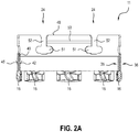
- FIGN. 2A-C show the cutting section 11 of FIG. 1 with the closed tubular element 14 and the drilling segments 16 in a longitudinal section along the section line AA in FIG FIG. 1A .
- the pipe element 14 is composed of a first pipe element 35 ( FIG. 2 B ) and a second tubular element 36 ( FIG. 2C ) composed.
- the first tubular element 35 is designed in the form of a first hollow cylinder with an annular cross-sectional area.
- the first tubular element 35 comprises a first outer jacket surface 41 , a first inner jacket surface 42 , a first lower end surface 43 and a first upper end surface 44 .
- the dimensions of the first tubular element 35 are defined by a first hollow cylinder height H 1 , a first inner diameter d 1 and a first outer diameter D 1 .
- the width of the first tubular element 35 results as half the difference between the first outside diameter D 1 and the first inside diameter d 1 and is referred to as the first width B 1 .
- the second tubular element 36 is designed in the form of a second hollow cylinder with an annular cross-sectional area.
- the second tubular element 36 comprises a second outer jacket surface 45 , a second inner jacket surface 46 , a second lower end surface 47 and a second upper end surface 48 .
- the dimensions of the second tubular element 36 are defined by a second hollow cylinder height H 2 , a second inner diameter d 2 and a second outer diameter D 2 .
- the width of the second tubular element 36 results as half the difference between the second outside diameter D 2 and the second inside diameter d 2 and is referred to as the second width B 2 .
- the first lower end face 43 of the first tubular element 35 and the second lower end face 47 of the second tubular element 36 are aligned flush.
- the flush alignment of the first lower end face 43 and the second lower end face 47 has the The advantage that a wide connection surface is created for the drilling segments 16, on which the drilling segments 16 can be connected to the first tubular element 35 and the second tubular element 36.
- the cutting section 11 is constructed in such a way that the force is transmitted from the drill shaft section 12 to the cutting section 11 via the first tubular element 35 and the torque is transmitted from the drill shaft section 12 to the cutting section 11 via the second tubular element 36.
- the first upper end face 44 of the first tubular element 35 forms on the inside of the cutting section 11 an annular stop shoulder 49 for the transmission of force from a connected drill shaft section.
- the torque is transmitted from the drill shaft section 12 to the cutting section 11 via the pin elements 23 and the slot-shaped recesses 24.
- the second tubular element 36 of the cutting section 11 has a plurality of slot-shaped recesses 24 on the second upper end face 48.
- the slot-shaped recesses 24 each include a transverse slot 51 and a connecting slot 52 , the connecting slot 52 connecting the transverse slot 51 to the second upper end face 48.
- the first tubular element 35 can be produced from a first material and the second tubular element 36 from a second material. By separating the cutting section 11 into the first tubular element 35 and the second tubular element 36, the selection of the first material and the second material can be adapted to the different requirements of the first tubular element 35 and the second tubular element 36.
- FIGN. 3A-C show a first sheet metal part 61 ( FIG. 3A ) and a second sheet metal part 62 ( FIG. 3B ), which are connected to form a double sheet metal part 63 .
- the closed tubular element 14 of the cutting section 11 is produced from the first sheet metal part 61 and the second sheet metal part 62 with the aid of the method according to the invention.
- the first sheet metal part 61 is designed as a flat sheet metal part of a first sheet metal thickness b 1 , which has a first height h 1 between first end faces 64 , 65 and a first length l 1 between first abutting edges 66, 67 .
- the second sheet metal part 62 is designed as a flat sheet metal part of a second sheet metal thickness b 2 , which has a second height h 2 between second end faces 68 , 69 and a second length l 2 between second abutting edges 70 , 71 .
- the first sheet metal part 61 and the second sheet metal part 62 are aligned with one another, the first sheet metal part 61 being arranged on the second sheet metal part 62.
- the first lower end face 64 and the second lower end face 68 are aligned flush.
- the first and second sheet metal parts 61, 62 are in the aligned state connected to one another to form the double sheet metal part 63 by means of a weld seam 72.
- the weld seam is placed in the center of the first and second sheet metal parts 61, 62.
Landscapes
- Engineering & Computer Science (AREA)
- Mechanical Engineering (AREA)
- Mining & Mineral Resources (AREA)
- Processing Of Stones Or Stones Resemblance Materials (AREA)
- Drilling Tools (AREA)
Description
- Die vorliegende Erfindung betrifft ein Verfahren zur Herstellung eines Schneidabschnittes für eine Bohrkrone.
-
GB 1 583 860 A - ▪ ein erstes Blechteil, das eine erste Höhe zwischen ersten Stirnflächen, eine erste Länge zwischen ersten Stosskanten und eine erste Blechdicke aufweist, wird gefertigt,
- ▪ ein zweites Blechteil, das eine zweite Höhe zwischen zweiten Stirnflächen, eine zweite Länge zwischen zweiten Stosskanten und eine zweite Blechdicke aufweist, wird gefertigt, wobei die erste Länge kleiner als die zweite Länge ist,
- ▪ das erste und zweite Blechteil werden umgeformt und miteinander zu einem geschlossenen Rohrelement verbunden und
- ▪ ein oder mehrere Bohrsegmente werden mit dem geschlossenen Rohrelement verbunden.
-
WO 2014/096359 A1 offenbart einen Schneidabschnitt für eine Bohrkrone, der mit einem Bohrschaftabschnitt der Bohrkrone über eine lösbare Verbindungseinrichtung verbindbar ist. Dabei ist die lösbare Verbindungseinrichtung als kombinierte Steck-Dreh-Verbindung ausgebildet. Als "Steck-Dreh-Verbindung" werden lösbare Verbindungen zwischen einem ersten und zweiten Verbindungselement bezeichnet, die in einer Richtung eine Steckverbindung bilden und zusätzlich über eine Drehverbindung verbunden werden. Der Schneidabschnitt umfasst eine oder mehrere Bohrsegmente, einen Ringabschnitt, ein äusseres Steckelement und eine ringförmige Anschlagschulter am Übergang vom Ringabschnitt zum äusseren Steckelement. - Schneidabschnitte, die mit einer kombinierten Steck-Dreh-Verbindung verbindbar sind, werden unter dem Produktnamen "Hilti DD X-CM" vertrieben. Die Schneidabschnitte "Hilti DD X-CM" umfassen mehrere Bohrsegmente, einen Ringabschnitt und ein äusseres Steckelement, wobei sich am Übergang vom Ringabschnitt zum äusseren Steckelement eine ringförmige Anschlagschulter für die Kraftübertragung befindet. Die Drehmomentübertragung erfolgt mithilfe von Stiftelementen, die mit schlitzförmigen Ausnehmungen im äusseren Steckelement zusammenwirken. Die Schneidabschnitte "Hilti DD X-CM" werden aus einem geschlossenen Rohrelement gefertigt. Dabei wird die ringförmige Anschlagschulter durch Drehbearbeitung erzeugt und die schlitzförmigen Ausnehmungen werden durch Fräsbearbeitung erzeugt.
- Nachteilig am Aufbau der bekannten Schneidabschnitte "Hilti DD X-CM" sind der hohe Fertigungsaufwand durch die Drehbearbeitung der ringförmigen Anschlagschulter und die Fräsbearbeitung der schlitzförmigen Ausnehmungen. Ausserdem ist die Materialauswahl für den Ringabschnitt und das äussere Steckelement eingeschränkt. Da die Schneidabschnitte "Hilti DD X-CM" aus einem geschlossenen Rohrelement gefertigt werden, muss hinsichtlich der Anforderungen an den Schneidabschnitt bezüglich Kraftübertragung, Drehmomentübertragung und Zugbelastungen beim Entfernen einer verklemmten Bohrkrone ein Kompromiss bei der Materialauswahl getroffen werden.
- Die Aufgabe der vorliegenden Erfindung besteht darin, bei einem Verfahren zur Herstellung eines Schneidabschnittes für eine Bohrkrone den Fertigungsaufwand bei der Herstellung des Schneidabschnittes zu reduzieren. Ausserdem soll die Funktionalität des Schneidabschnittes beim Bohren mit der Bohrkrone im Hinblick auf Kraftübertragung, Drehmomentübertragung und/oder Zugbelastungen beim Entfernen einer verklemmten Bohrkrone verbessert werden. Diese Aufgabe wird bei dem eingangs genannten Verfahren zur Herstellung eines Schneidabschnittes für eine Bohrkrone erfindungsgemäß durch die Merkmale des unabhängigen Anspruchs 1 gelöst. Vorteilhafte Weiterbildungen sind in den abhängigen Ansprüchen angegeben.
- Der mit dem erfindungsgemäßen Verfahren hergestellte Schneidabschnitt für eine Bohrkrone wird mit einem Bohrschaftabschnitt der Bohrkrone über eine lösbare Verbindungseinrichtung verbunden. Das Verfahren zur Herstellung eines Schneidabschnittes für eine Bohrkrone umfasst die Verfahrenschritte:
- ▪ ein erstes Blechteil, das eine erste Höhe zwischen ersten Stirnflächen, eine erste Länge zwischen ersten Stosskanten und eine erste Blechdicke aufweist, wird gefertigt,
- ▪ ein zweites Blechteil, das eine zweite Höhe zwischen zweiten Stirnflächen, eine zweite Länge zwischen zweiten Stosskanten und eine zweite Blechdicke aufweist, wird gefertigt, wobei die erste Höhe kleiner als die zweite Höhe ist und die erste Länge kleiner als die zweite Länge ist,
- ▪ das erste und zweite Blechteil werden zueinander ausgerichtet, wobei das erste Blechteil auf dem zweiten Blechteil angeordnet wird,
- ▪ das erste und zweite Blechteil werden im ausgerichteten Zustand miteinander zu einem Doppelblechteil verbunden,
- ▪ das Doppelblechteil wird zu einem offenen Rohrelement umgeformt, wobei das erste Blechteil auf der Innenseite des offenen Rohrelementes angeordnet wird,
- ▪ das offene Rohrelement wird zumindest an den zweiten Stosskanten des zweiten Blechteils zu einem geschlossenen Rohrelement verbunden und
- ▪ ein oder mehrere Bohrsegmente werden mit dem geschlossenen Rohrelement verbunden.
- Der Schneidabschnitt, der mithilfe des erfindungsgemässen Verfahrens hergestellt wird, umfasst ein geschlossenes Rohrelement, das aus einem ersten Rohrelement und einem zweiten Rohrelement zusammengesetzt ist, und mindestens ein Bohrsegment. Das geschlossene Rohrelement wird aus einem ersten Blechteil und einem zweiten Blechteil hergestellt. Das erste Blechteil ist als ebenes Blechteil einer ersten Blechdicke ausgebildet, das eine erste Höhe zwischen ersten Stirnflächen und eine erste Länge zwischen ersten Stosskanten aufweist. Das zweite Blechteil ist als ebenes Blechteil einer zweiten Blechdicke ausgebildet, das eine zweite Höhe zwischen zweiten Stirnflächen und eine zweite Länge zwischen zweiten Stosskanten aufweist. Das erste Blechteil und das zweite Blechteil werden zueinander ausgerichtet und im ausgerichteten Zustand miteinander zu einem Doppelblechteil verbunden. Das Doppelblechteil wird zu einem offenen Rohrelement umgeformt und zumindest an den zweiten Stosskanten des zweiten Blechteils zum geschlossenen Rohrelement verbunden.
- Der Schneidabschnitt ist so aufgebaut, dass die Kraftübertragung auf den Schneidabschnitt über das erste ohrelement und die Drehmomentübertragung auf den Schneidabschnitt über das zweite Rohrelement erfolgt. Die erste obere Stirnfläche des ersten Rohrelementes bildet eine ringförmige Anschlagschulter, die zur Kraftübertragung verwendet wird. Ein Bohrschaftabschnitt überträgt die Kraft mittels einer ringförmigen Stirnfläche auf die ringförmige Anschlagschulter. Die Drehmomentübertragung erfolgt beispielsweise über Stiftelemente des Bohrschaftabschnittes, die mit schlitzförmigen Ausnehmungen im zweiten geschlossenen Rohrelement zusammenwirken. Durch die Trennung des Schneidabschnittes in das erste Rohrelement und das zweite Rohrelement können die unterschiedlichen Anforderungen an den Schneidabschnitt im Hinblick auf die Kraftübertragung und Drehmomentübertragung berücksichtigt werden.
- Durch die Trennung des Schneidabschnittes in das erste Rohrelement und das zweite Rohrelement kann ausserdem der Fertigungsaufwand für die Herstellung des Schneidabschnittes reduziert werden. Die erste obere Stirnfläche bildet die ringförmige Anschlagschulter für die Kraftübertragung, so dass eine Drehbearbeitung entfällt. Das erste Rohrelement und das zweite Rohrelement sind als Hohlzylinder mit kreisringförmigen Querschnitten ausgebildet und weisen eine konstante Materialstärke auf.
- Bevorzugt wird das geschlossene Rohrelement zusätzlich an den ersten Stosskanten des ersten Blechteils verbunden. Besonders bevorzugt wird das offene Rohrelement gleichzeitig an den ersten Stosskanten des ersten Blechteils und den zweiten Stosskanten des zweiten Blechteils verbunden.
- Bevorzugt wird im zweiten Blechteil mindestens eine schlitzförmige Ausnehmung erstellt, wobei die mindestens eine schlitzförmige Ausnehmung einen Querschlitz und einen Verbindungsschlitz umfasst und der Verbindungsschlitz den Querschlitz mit der zweiten oberen Stirnfläche des zweiten geschlossenen Rohrelementes verbindet. Die mindestens eine schlitzförmige Ausnehmung ist Teil der lösbaren Verbindungseinrichtung, die den Schneidabschnitt mit einem Bohrschaftabschnitt der Bohrkrone verbindet. Die schlitzförmige Ausnehmung ist in T-Form oder L-Form ausgebildet und ermöglicht im verbundenen Zustand der Bohrkrone eine Relativbewegung zwischen dem Schneidabschnitt und dem Bohrschaftabschnitt. Durch die Relativbewegung zwischen dem Schneidabschnitt und dem Bohrschaftabschnitt kann ein verklemmter Schneidabschnitt aus dem Untergrund gelöst werden.
- Besonders bevorzugt wird im zweiten Blechteil mindestens eine Quernut erstellt, wobei die mindestens eine Quernut in Höhe des Verbindungsschlitzes der mindestens einen schlitzförmigen Ausnehmung angeordnet wird. Die mindestens eine Quernut ist Teil der lösbaren Verbindungseinrichtung, die den Schneidabschnitt mit einem Bohrschaftabschnitt der Bohrkrone verbindet. Die Breite der Quernut ist grösser oder gleich der Breite des Querschlitzes der mindestens einen schlitzförmigen Ausnehmung. In die Quernut des Schneidabschnittes greift eine passende Quernase eines Bohrschaftabschnittes ein. Die Quernut und Quernase bilden eine zusätzliche formschlüssige Verbindung, die verhindert, dass die Steck-Dreh-Verbindung beim Lösen einer verklemmten Bohrkrone unbeabsichtigt geöffnet wird und der Bohrschaftabschnitt ohne Schneidabschnitt aus dem Untergrund entfernt wird.
- Bevorzugt wird im ersten Blechteil mindestens eine Innenvertiefung erstellt, die sich über die erste Hohlzylinderhöhe erstreckt. Die mindestens eine Innenvertiefung in der ersten inneren Mantelfläche kann einen Transportkanal für eine Kühl- und Spülflüssigkeit bilden und ermöglicht die Ausbildung von Schneidabschnitten mit geringen Innenüberständen der Bohrsegmente auf der Innenseite des Schneidabschnittes. Die Breite, Tiefe, Form und/oder Anzahl der mindestens einen Innenvertiefung werden an die benötigte Flüssigkeitsmenge der Kühl- und Spülflüssigkeit angepasst.
- In einer bevorzugten Weiterentwicklung wird das erste Blechteil aus einem ersten Material und das zweite Blechteil aus einem zweiten Material hergestellt. Der mit dem erfindungsgemäßen Verfahren hergestellte Schneidabschnitt ist so aufgebaut, dass die Kraftübertragung auf den Schneidabschnitt über das erste Rohrelement und die Drehmomentübertragung auf den Schneidabschnitt über das zweite Rohrelement erfolgt. Durch die Trennung des Schneidabschnittes in das erste Rohrelement und das zweite Rohrelement kann die Auswahl des ersten Materials und des zweiten Materials an die unterschiedlichen Anforderungen an den Schneidabschnitt im Hinblick auf die Kraftübertragung und Drehmomentübertragung angepasst werden. Ausserdem kann das zweite Material im Hinblick auf Zugbelastungen beim Entfernen einer verklemmten Bohrkrone angepasst werden.
- Bevorzugt wird das zweite Blechteil an den zweiten Stosskanten mit mindestens einem zweiten positiven Formschlusselement und mindestens einem entsprechenden zweiten negativen Formschlusselement ausgebildet, wobei das mindestens eine zweite positive Formschlusselement und das mindestens eine zweite negative Formschlusselement formschlüssig verbunden werden. Die Verbindung der zweiten Stosskanten über zweite Formschlusselemente hat den Vorteil, dass kein Wärmeeintrag in das zweite Rohrelement erfolgt, der zu Spannungen im zweiten Rohrelement führen kann.
- Ausführungsbeispiele der Erfindung werden nachfolgend anhand der Zeichnung beschrieben. Diese soll die Ausführungsbeispiele nicht notwendigerweise maßstäblich darstellen, vielmehr ist die Zeichnung, wo zur Erläuterung dienlich, in schematischer und/oder leicht verzerrter Form ausgeführt. Der Einfachheit halber sind nachfolgend für identische oder ähnliche Teile oder Teile mit identischer oder ähnlicher Funktion gleiche Bezugszeichen verwendet.
- Es zeigen:
- FIGN. 1A,
- B eine Bohrkrone mit einem Schneidabschnitt und einem Bohrschaftabschnitt, die über eine lösbare Verbindungseinrichtung verbindbar sind, in einem unverbundenen Zustand der Bohrkrone (
FIG. 1A ) und in einem verbundenen Zustand der Bohrkrone (FIG. 1B ); - FIGN. 2A-C
- den Schneidabschnitt der
FIG. 1 bestehend aus einem geschlossenen Rohrelement und mehreren Bohrsegmenten in einem Längsschnitt entlang der Schnittlinie A-A inFIG. 1A ; und - FIGN. 3A-B
- ein erstes Blechteil (
FIG. 3A ) und ein zweites Blechteil (FIG. 3B ), die zu einem Doppelblechteil verbunden werden (FIG. 3C ). -
FIGN. 1A , B zeigen eine Bohrkrone 10, die einen Schneidabschnitt 11 und einen Bohrschaftabschnitt 12 umfasst, wobei der Schneidabschnitt 11 und der Bohrschaftabschnitt 12 über eine lösbare Verbindungseinrichtung 13 verbindbar sind. Dabei zeigtFIG. 1A den Schneidabschnitt 11 und Bohrschaftabschnitt 12 in einem unverbundenen Zustand der Bohrkrone undFIG. 1B zeigt den Schneidabschnitt 11 und Bohrschaftabschnitt 12 in einem verbundenen Zustand der Bohrkrone. - Der Schneidabschnitt 11 umfasst ein geschlossenes Rohrelement 14 und mehrere Bohrsegmente 16, die mit dem geschlossenen Rohrelement 14 verbunden sind. Der Schneidabschnitt 11 wird mithilfe des erfindungsgemässen Verfahrens zur Herstellung eines Schneidabschnittes hergestellt. Das Rohrelement 14 ist aus zwei ebenen Blechteilen hergestellt, die miteinander verbunden werden und zu einem offenen Rohrelement umgeformt werden. Das offene Rohrelement wird durch Verbinden der Stosskanten zu einem geschlossenen Rohrelement.
- Die Bohrsegmente 16 sind ringförmig angeordnet und bilden einen Bohrring mit Zwischenräumen. Der Schneidabschnitt 11 kann anstatt mehrerer Bohrsegmente 16 auch ein einzelnes als geschlossener Bohrring ausgebildetes Bohrsegment aufweisen. Die Bohrsegmente 16 können mit dem geschlossenen Rohrelement 14 verschweißt, verlötet, verschraubt oder in einer anderen geeigneten Befestigungsart am geschlossenen Rohrelement 14 befestigt werden. Der Bohrschaftabschnitt 12 umfasst einen rohrförmigen Bohrschaft 17, einen Deckel 18 und ein Einsteckende 19, über das die Bohrkrone 10 in einer Werkzeugaufnahme eines Kernbohrgerätes befestigt wird.
- Die lösbare Verbindungseinrichtung 13 ist in Form einer kombinierten Steck-Dreh-Verbindung ausgebildet, wie sie in
WO 2014/096359 A1 offenbart ist. Die lösbare Verbindungseinrichtung 13 umfasst ein erstes Steckelement 21, das in den Schneidabschnitt 11 integriert ist, und ein zweites Steckelement 22, das in den Bohrschaftabschnitt 12 integriert ist. Das erste und zweite Steckelement 21, 22 bilden eine Steckverbindung und werden zusätzlich über eine Drehverbindung gesichert. Die Drehverbindung umfasst mehrere Stiftelemente 23, die in schlitzförmige Ausnehmungen 24 eingeführt werden. Die Stiftelemente 23 sind an einer Außenseite des zweiten Steckelementes 22 befestigt und die schlitzförmigen Ausnehmungen 24 sind im ersten Steckelement 21 vorgesehen. Der Schneidabschnitt 11 lässt sich vom Bediener einfach und schnell mit dem Bohrschaftabschnitt 12 verbinden. Dazu wird der Schneidabschnitt 11 mit dem ersten Steckelement 21 so auf das zweite Steckelement 22 des Bohrschaftabschnittes 12 gesteckt, dass die Stiftelemente 23 in den schlitzförmigen Ausnehmungen 24 angeordnet sind. - Im Bohrbetrieb wird die Bohrkrone 10 von einem Kernbohrgerät in einer Drehrichtung 25 um eine Drehachse 26 angetrieben, wobei die Drehachse 26 mit einer Längsachse des rohrförmigen Bohrschaftes 17 zusammenfällt. Während der Drehung der Bohrkrone 10 um die Drehachse 26 wird die Bohrkrone 10 entlang einer Vorschubrichtung 27 in ein Werkstück 28 bewegt, wobei die Vorschubrichtung 27 parallel zur Drehachse 26 verläuft. Die Bohrkrone 10 erzeugt im Werkstück 28 ein Bohrloch 31 mit einem Bohrlochdurchmesser dL und einen Bohrkern 32 mit einem Kerndurchmesser dK . Die Bohrsegmente 15 bilden einen Bohrring mit einem Außendurchmesser, der dem Bohrlochdurchmesser dL entspricht, und einem Innendurchmesser, der dem Kerndurchmesser dK entspricht.
-
FIGN. 2A-C zeigen den Schneidabschnitt 11 derFIG. 1 mit dem geschlossenen Rohrelement 14 und den Bohrsegmenten 16 in einem Längsschnitt entlang der Schnittlinie A-A inFIG. 1A . Das Rohrelement 14 ist aus einem ersten Rohrelement 35 (FIG. 2B ) und einem zweiten Rohrelement 36 (FIG. 2C ) zusammengesetzt. - Das erste Rohrelement 35 ist in Form eines ersten Hohlzylinders mit einer kreisringförmigen Querschnittsfläche ausgebildet. Das erste Rohrelement 35 umfasst eine erste äussere Mantelfläche 41, eine erste innere Mantelfläche 42, eine erste untere Stirnfläche 43 und eine erste obere Stirnfläche 44. Die Abmessungen des ersten Rohrelementes 35 sind durch eine erste Hohlzylinderhöhe H1 , einen ersten Innendurchmesser d1 und einen ersten Aussendurchmesser D1 definiert. Die Breite des ersten Rohrelementes 35 ergibt sich als halbe Differenz des ersten Aussendurchmessers D1 und des ersten Innendurchmessers d1 und wird als erste Breite B1 bezeichnet.
- Das zweite Rohrelement 36 ist in Form eines zweiten Hohlzylinders mit einer kreisringförmigen Querschnittsfläche ausgebildet. Das zweite Rohrelement 36 umfasst eine zweite äussere Mantelfläche 45, eine zweite innere Mantelfläche 46, eine zweite untere Stirnfläche 47 und eine zweite obere Stirnfläche 48. Die Abmessungen des zweiten Rohrelementes 36 sind durch eine zweite Hohlzylinderhöhe H2 , einen zweiten Innendurchmesser d2 und einen zweiten Aussendurchmesser D2 definiert. Die Breite des zweiten Rohrelementes 36 ergibt sich als halbe Differenz des zweiten Aussendurchmessers D2 und des zweiten Innendurchmessers d2 und wird als zweite Breite B2 bezeichnet.
- Die erste untere Stirnfläche 43 des ersten Rohrelementes 35 und die zweite untere Stirnfläche 47 des zweiten Rohrelementes 36 sind bündig ausgerichtet. Die bündige Ausrichtung der ersten unteren Stirnfläche 43 und der zweiten unteren Stirnfläche 47 hat den Vorteil, dass eine breite Anbindungsfläche für die Bohrsegmente 16 entsteht, an der die Bohrsegmente 16 mit dem ersten Rohrelement 35 und dem zweiten Rohrelement 36 verbunden werden können.
- Der Schneidabschnitt 11 ist so aufgebaut, dass die Kraftübertragung vom Bohrschaftabschnitt 12 auf den Schneidabschnitt 11 über das erste Rohrelement 35 erfolgt und die Drehmomentübertragung vom Bohrschaftabschnitt 12 auf den Schneidabschnitt 11 über das zweite Rohrelement 36 erfolgt. Die erste obere Stirnfläche 44 des ersten Rohrelementes 35 bildet an der Innenseite des Schneidabschnittes 11 eine ringförmige Anschlagschulter 49 für die Kraftübertragung von einem verbundenen Bohrschaftabschnitt. Die Drehmomentübertragung vom Bohrschaftabschnitt 12 auf den Schneidabschnitt 11 erfolgt über die Stiftelemente 23 und die schlitzförmigen Ausnehmungen 24. Das zweite Rohrelement 36 des Schneidabschnittes 11 weist an der zweiten oberen Stirnfläche 48 mehrere schlitzförmige Ausnehmungen 24 auf. Die schlitzförmigen Ausnehmungen 24 umfassen jeweils einen Querschlitz 51 und einen Verbindungsschlitz 52, wobei der Verbindungsschlitz 52 den Querschlitz 51 mit der zweiten oberen Stirnfläche 48 verbindet.
- Das erste Rohrelement 35 kann aus einem ersten Material und das zweite Rohrelement 36 aus einem zweiten Material hergestellt werden. Durch die Trennung des Schneidabschnittes 11 in das erste Rohrelement 35 und das zweite Rohrelement 36 kann die Auswahl des ersten Materials und des zweiten Materials an die unterschiedlichen Anforderungen des ersten Rohrelementes 35 und des zweiten Rohrelementes 36 angepasst werden.
-
FIGN. 3A-C zeigen ein erstes Blechteil 61 (FIG. 3A ) und ein zweites Blechteil 62 (FIG. 3B ), die zu einem Doppelblechteil 63 verbunden werden. Das geschlossene Rohrelement 14 des Schneidabschnittes 11 wird mithilfe des erfindungsgemässen Verfahrens aus dem ersten Blechteil 61 und dem zweiten Blechteil 62 hergestellt. - Das erste Blechteil 61 ist als ebenes Blechteil einer ersten Blechdicke b1 ausgebildet, das eine erste Höhe h1 zwischen ersten Stirnflächen 64, 65 und eine erste Länge l1 zwischen ersten Stosskanten 66, 67 aufweist. Das zweite Blechteil 62 ist als ebenes Blechteil einer zweiten Blechdicke b2 ausgebildet, das eine zweite Höhe h2 zwischen zweiten Stirnflächen 68, 69 und eine zweite Länge l2 zwischen zweiten Stosskanten 70, 71 aufweist.
- Das erste Blechteil 61 und das zweite Blechteil 62 werden zueinander ausgerichtet, wobei das erste Blechteil 61 auf dem zweiten Blechteil 62 angeordnet wird. Im Ausführungsbeispiel werden die erste untere Stirnfläche 64 und die zweite untere Stirnfläche 68 bündig ausgerichtet. Das erste und zweite Blechteil 61, 62 werden im ausgerichteten Zustand mithilfe einer Schweissnaht 72 miteinander zum Doppelblechteil 63 verbunden. Die Schweissnaht wird im Bereich der Mitte des ersten und zweiten Blechteils 61, 62 platziert.
Claims (8)
- Verfahren zur Herstellung eines Schneidabschnittes (11) für eine Bohrkrone (10), wobei der Schneidabschnitt (11) über eine lösbare Verbindungseinrichtung (13) mit einem Bohrschaftabschnitt (12) der Bohrkrone (10) verbunden wird, mit den Verfahrenschritten:▪ ein erstes Blechteil (61), das eine erste Höhe (h1) zwischen ersten Stirnflächen (64, 65), eine erste Länge (l1) zwischen ersten Stosskanten (66, 67) und eine erste Blechdicke (bi) aufweist, wird gefertigt,▪ ein zweites Blechteil (62), das eine zweite Höhe (h2) zwischen zweiten Stirnflächen (68, 69), eine zweite Länge (l2) zwischen zweiten Stosskanten (70, 71) und eine zweite Blechdicke (b2) aufweist, wird gefertigt, wobei die erste Höhe (h1) kleiner als die zweite Höhe (h2) ist und die erste Länge (l1) kleiner als die zweite Länge (l2) ist,▪ das erste und zweite Blechteil (61, 62) werden zueinander ausgerichtet, wobei das erste Blechteil (61) auf dem zweiten Blechteil (62) angeordnet wird,▪ das erste Blechteil (61) und zweite Blechteil (62) werden im ausgerichteten Zustand miteinander zu einem Doppelblechteil (63) verbunden,▪ das Doppelblechteil (63) wird zu einem offenen Rohrelement umgeformt, wobei das erste Blechteil (61) auf der Innenseite des offenen Rohrelementes angeordnet wird,▪ das offene Rohrelement wird zumindest an den zweiten Stosskanten (70, 71) des zweiten Blechteils (62) zu einem geschlossenen Rohrelement (14) verbunden und▪ ein oder mehrere Bohrsegmente (16) werden mit dem geschlossenen Rohrelement (14) verbunden.
- Verfahren nach Anspruch 1, dadurch gekennzeichnet, dass das geschlossene Rohrelement (14) zusätzlich an den ersten Stosskanten (66, 67) des ersten Blechteils (61) verbunden wird.
- Verfahren nach Anspruch 2, dadurch gekennzeichnet, dass das offene Rohrelement gleichzeitig an den ersten Stosskanten (66, 67) des ersten Blechteils (61) und den zweiten Stosskanten (70, 71) des zweiten Blechteils (62) verbunden wird.
- Verfahren nach Anspruch 1, dadurch gekennzeichnet, dass im zweiten Blechteil (62) mindestens eine schlitzförmige Ausnehmung (24) erstellt wird, wobei die mindestens eine schlitzförmige Ausnehmung (24) einen Querschlitz (51) und einen Verbindungsschlitz (52) aufweist und der Verbindungsschlitz (52) den Querschlitz (51) mit der zweiten Stirnfläche (69) des zweiten Blechteils (62) verbindet.
- Verfahren nach Anspruch 4, dadurch gekennzeichnet, dass im zweiten Blechteil (62) mindestens eine Quernut (53) erstellt wird, wobei die mindestens eine Quernut (53) in Höhe des Verbindungsschlitzes (52) angeordnet wird.
- Verfahren nach Anspruch 1, dadurch gekennzeichnet, dass im ersten Blechteil (61) mindestens eine Innenvertiefung erstellt wird, die sich über die erste Höhe (h1) des ersten Blechteils (61) erstreckt.
- Verfahren nach einem der Ansprüche 1 bis 6, dadurch gekennzeichnet, dass das erste Blechteil (61) aus einem ersten Material und das zweite Blechteil (71) aus einem zweiten Material hergestellt wird.
- Verfahren nach einem der Ansprüche 1 bis 7, dadurch gekennzeichnet, dass das zweite Blechteil (62) an den zweiten Stosskanten (70, 71) mit mindestens einem zweiten positiven Formschlusselement und mindestens einem entsprechenden zweiten negativen Formschlusselement ausgebildet wird, wobei das mindestens eine zweite positive Formschlusselement und das mindestens eine zweite negative Formschlusselement formschlüssig verbunden werden.
Applications Claiming Priority (2)
| Application Number | Priority Date | Filing Date | Title |
|---|---|---|---|
| EP17209398.1A EP3501702A1 (de) | 2017-12-21 | 2017-12-21 | Verfahren zur herstellung eines schneidabschnittes für eine bohrkrone |
| PCT/EP2018/084733 WO2019121314A1 (de) | 2017-12-21 | 2018-12-13 | Verfahren zur herstellung eines schneidabschnittes für eine bohrkrone |
Publications (2)
| Publication Number | Publication Date |
|---|---|
| EP3727730A1 EP3727730A1 (de) | 2020-10-28 |
| EP3727730B1 true EP3727730B1 (de) | 2021-11-17 |
Family
ID=60781833
Family Applications (2)
| Application Number | Title | Priority Date | Filing Date |
|---|---|---|---|
| EP17209398.1A Withdrawn EP3501702A1 (de) | 2017-12-21 | 2017-12-21 | Verfahren zur herstellung eines schneidabschnittes für eine bohrkrone |
| EP18814959.5A Active EP3727730B1 (de) | 2017-12-21 | 2018-12-13 | Verfahren zur herstellung eines schneidabschnittes für eine bohrkrone |
Family Applications Before (1)
| Application Number | Title | Priority Date | Filing Date |
|---|---|---|---|
| EP17209398.1A Withdrawn EP3501702A1 (de) | 2017-12-21 | 2017-12-21 | Verfahren zur herstellung eines schneidabschnittes für eine bohrkrone |
Country Status (3)
| Country | Link |
|---|---|
| US (1) | US11504815B2 (de) |
| EP (2) | EP3501702A1 (de) |
| WO (1) | WO2019121314A1 (de) |
Families Citing this family (3)
| Publication number | Priority date | Publication date | Assignee | Title |
|---|---|---|---|---|
| TWI828595B (zh) * | 2023-06-09 | 2024-01-01 | 國立中央大學 | 切削刀具之設計方法 |
| EP4667144A1 (de) * | 2024-06-18 | 2025-12-24 | Hilti Aktiengesellschaft | Werkzeugeinsatz zum kernbohren mit verbesserter führung |
| CN120558612B (zh) * | 2025-06-05 | 2025-11-11 | 中国地质科学院 | 用于钨铍矿山地质勘查现场的岩心切割取样设备及取样方法 |
Family Cites Families (6)
| Publication number | Priority date | Publication date | Assignee | Title |
|---|---|---|---|---|
| GB1583860A (en) * | 1976-08-20 | 1981-02-04 | Moppes & Sons Ltd L Van | Core drills |
| US4362161A (en) * | 1980-10-27 | 1982-12-07 | Codman & Shurtleff, Inc. | Cranial drill |
| EP2135568B1 (de) * | 2004-06-21 | 2011-12-07 | Straumann Holding AG | Verfahren zur Herstellung von Einwegdrehschneidwerkzeugen und Einwegdrehwerkzeug für dentale oder medizinische Anwendungen |
| ATE517703T1 (de) * | 2004-12-21 | 2011-08-15 | Bergrohr Gmbh Siegen | Mehrlagenrohr sowie verfahren zu seiner herstellung |
| EP2745964A1 (de) | 2012-12-21 | 2014-06-25 | HILTI Aktiengesellschaft | Schneidabschnitt |
| US11712742B2 (en) * | 2018-03-23 | 2023-08-01 | Edward M. GALIBER | Ring-saw assemblies and processes |
-
2017
- 2017-12-21 EP EP17209398.1A patent/EP3501702A1/de not_active Withdrawn
-
2018
- 2018-12-13 EP EP18814959.5A patent/EP3727730B1/de active Active
- 2018-12-13 US US16/954,463 patent/US11504815B2/en active Active
- 2018-12-13 WO PCT/EP2018/084733 patent/WO2019121314A1/de not_active Ceased
Also Published As
| Publication number | Publication date |
|---|---|
| WO2019121314A1 (de) | 2019-06-27 |
| EP3501702A1 (de) | 2019-06-26 |
| US11504815B2 (en) | 2022-11-22 |
| EP3727730A1 (de) | 2020-10-28 |
| US20210078119A1 (en) | 2021-03-18 |
Similar Documents
| Publication | Publication Date | Title |
|---|---|---|
| EP2934798B1 (de) | Bohrkrone mit einem austauschbaren schneidabschnitt | |
| EP2745964A1 (de) | Schneidabschnitt | |
| EP2745965A1 (de) | Bohrkrone mit einem austauschbaren Schneidabschnitt | |
| DE102015211744B4 (de) | Rotationswerkzeug, insbesondere Bohrer, und Schneidkopf für ein solches Rotationswerkzeug | |
| EP3727730A1 (de) | Verfahren zur herstellung eines schneidabschnittes für eine bohrkrone | |
| EP3727729B1 (de) | Verfahren zur herstellung eines schneidabschnittes für eine bohrkrone | |
| EP3727732B1 (de) | Schneidabschnitt für eine bohrkrone | |
| EP3029262A1 (de) | Bohrgestänge, verbindungssystem, erdbohrvorrichtung und verfahren zum verbinden eines bohrgestängeschusses | |
| EP3727731B1 (de) | Schneidabschitt für eine bohrkrone | |
| EP3727728B1 (de) | Schneidabschnitt für eine bohrkrone | |
| DE2533704A1 (de) | Kupplung | |
| EP3501711A1 (de) | Verfahren zur herstellung eines schneidabschnitt für eine bohrkrone | |
| DE2541423A1 (de) | Tiefbohrwerkzeug mit einem bohrkopf und einem langen schaft | |
| EP3727776B1 (de) | Schneidabschnitt für eine bohrkrone | |
| EP3501703A1 (de) | Verfahren zur herstellung eines schneidabschnitt für eine bohrkrone | |
| EP3501705A1 (de) | Verfahren zur herstellung eines schneidabschnittes für eine bohrkrone | |
| EP3501712A1 (de) | Verfahren zur herstellung eines schneidabschnitt für eine bohrkrone | |
| EP3501706A1 (de) | Verfahren zur herstellung eines schneidabschnittes für eine bohrkrone | |
| EP3501704A1 (de) | Verfahren zur herstellung eines schneidabschnittes für eine bohrkrone | |
| EP3501707A1 (de) | Schneidabschnitt für eine bohrkrone | |
| EP3727775B1 (de) | Schneidabschnitt für eine bohrkrone | |
| DE3205088A1 (de) | Mitnehmerkupplung fuer werkzeuge | |
| EP3184215A1 (de) | Set aus mehreren bohrschaftabschnitten zum aufbau einer bohrkrone | |
| CH705022B1 (de) | Bohrwerkzeug. |
Legal Events
| Date | Code | Title | Description |
|---|---|---|---|
| STAA | Information on the status of an ep patent application or granted ep patent |
Free format text: STATUS: UNKNOWN |
|
| STAA | Information on the status of an ep patent application or granted ep patent |
Free format text: STATUS: THE INTERNATIONAL PUBLICATION HAS BEEN MADE |
|
| PUAI | Public reference made under article 153(3) epc to a published international application that has entered the european phase |
Free format text: ORIGINAL CODE: 0009012 |
|
| STAA | Information on the status of an ep patent application or granted ep patent |
Free format text: STATUS: REQUEST FOR EXAMINATION WAS MADE |
|
| 17P | Request for examination filed |
Effective date: 20200721 |
|
| AK | Designated contracting states |
Kind code of ref document: A1 Designated state(s): AL AT BE BG CH CY CZ DE DK EE ES FI FR GB GR HR HU IE IS IT LI LT LU LV MC MK MT NL NO PL PT RO RS SE SI SK SM TR |
|
| AX | Request for extension of the european patent |
Extension state: BA ME |
|
| DAV | Request for validation of the european patent (deleted) | ||
| DAX | Request for extension of the european patent (deleted) | ||
| GRAP | Despatch of communication of intention to grant a patent |
Free format text: ORIGINAL CODE: EPIDOSNIGR1 |
|
| STAA | Information on the status of an ep patent application or granted ep patent |
Free format text: STATUS: GRANT OF PATENT IS INTENDED |
|
| INTG | Intention to grant announced |
Effective date: 20210820 |
|
| GRAS | Grant fee paid |
Free format text: ORIGINAL CODE: EPIDOSNIGR3 |
|
| GRAA | (expected) grant |
Free format text: ORIGINAL CODE: 0009210 |
|
| STAA | Information on the status of an ep patent application or granted ep patent |
Free format text: STATUS: THE PATENT HAS BEEN GRANTED |
|
| AK | Designated contracting states |
Kind code of ref document: B1 Designated state(s): AL AT BE BG CH CY CZ DE DK EE ES FI FR GB GR HR HU IE IS IT LI LT LU LV MC MK MT NL NO PL PT RO RS SE SI SK SM TR |
|
| REG | Reference to a national code |
Ref country code: GB Ref legal event code: FG4D Free format text: NOT ENGLISH |
|
| REG | Reference to a national code |
Ref country code: DE Ref legal event code: R096 Ref document number: 502018007924 Country of ref document: DE |
|
| REG | Reference to a national code |
Ref country code: IE Ref legal event code: FG4D Free format text: LANGUAGE OF EP DOCUMENT: GERMAN |
|
| REG | Reference to a national code |
Ref country code: AT Ref legal event code: REF Ref document number: 1447645 Country of ref document: AT Kind code of ref document: T Effective date: 20211215 |
|
| REG | Reference to a national code |
Ref country code: SE Ref legal event code: TRGR |
|
| REG | Reference to a national code |
Ref country code: LT Ref legal event code: MG9D |
|
| REG | Reference to a national code |
Ref country code: NL Ref legal event code: MP Effective date: 20211117 |
|
| PG25 | Lapsed in a contracting state [announced via postgrant information from national office to epo] |
Ref country code: RS Free format text: LAPSE BECAUSE OF FAILURE TO SUBMIT A TRANSLATION OF THE DESCRIPTION OR TO PAY THE FEE WITHIN THE PRESCRIBED TIME-LIMIT Effective date: 20211117 Ref country code: LT Free format text: LAPSE BECAUSE OF FAILURE TO SUBMIT A TRANSLATION OF THE DESCRIPTION OR TO PAY THE FEE WITHIN THE PRESCRIBED TIME-LIMIT Effective date: 20211117 Ref country code: FI Free format text: LAPSE BECAUSE OF FAILURE TO SUBMIT A TRANSLATION OF THE DESCRIPTION OR TO PAY THE FEE WITHIN THE PRESCRIBED TIME-LIMIT Effective date: 20211117 Ref country code: BG Free format text: LAPSE BECAUSE OF FAILURE TO SUBMIT A TRANSLATION OF THE DESCRIPTION OR TO PAY THE FEE WITHIN THE PRESCRIBED TIME-LIMIT Effective date: 20220217 |
|
| PG25 | Lapsed in a contracting state [announced via postgrant information from national office to epo] |
Ref country code: IS Free format text: LAPSE BECAUSE OF FAILURE TO SUBMIT A TRANSLATION OF THE DESCRIPTION OR TO PAY THE FEE WITHIN THE PRESCRIBED TIME-LIMIT Effective date: 20220317 Ref country code: PT Free format text: LAPSE BECAUSE OF FAILURE TO SUBMIT A TRANSLATION OF THE DESCRIPTION OR TO PAY THE FEE WITHIN THE PRESCRIBED TIME-LIMIT Effective date: 20220317 Ref country code: PL Free format text: LAPSE BECAUSE OF FAILURE TO SUBMIT A TRANSLATION OF THE DESCRIPTION OR TO PAY THE FEE WITHIN THE PRESCRIBED TIME-LIMIT Effective date: 20211117 Ref country code: NO Free format text: LAPSE BECAUSE OF FAILURE TO SUBMIT A TRANSLATION OF THE DESCRIPTION OR TO PAY THE FEE WITHIN THE PRESCRIBED TIME-LIMIT Effective date: 20220217 Ref country code: NL Free format text: LAPSE BECAUSE OF FAILURE TO SUBMIT A TRANSLATION OF THE DESCRIPTION OR TO PAY THE FEE WITHIN THE PRESCRIBED TIME-LIMIT Effective date: 20211117 Ref country code: LV Free format text: LAPSE BECAUSE OF FAILURE TO SUBMIT A TRANSLATION OF THE DESCRIPTION OR TO PAY THE FEE WITHIN THE PRESCRIBED TIME-LIMIT Effective date: 20211117 Ref country code: HR Free format text: LAPSE BECAUSE OF FAILURE TO SUBMIT A TRANSLATION OF THE DESCRIPTION OR TO PAY THE FEE WITHIN THE PRESCRIBED TIME-LIMIT Effective date: 20211117 Ref country code: GR Free format text: LAPSE BECAUSE OF FAILURE TO SUBMIT A TRANSLATION OF THE DESCRIPTION OR TO PAY THE FEE WITHIN THE PRESCRIBED TIME-LIMIT Effective date: 20220218 |
|
| PG25 | Lapsed in a contracting state [announced via postgrant information from national office to epo] |
Ref country code: SM Free format text: LAPSE BECAUSE OF FAILURE TO SUBMIT A TRANSLATION OF THE DESCRIPTION OR TO PAY THE FEE WITHIN THE PRESCRIBED TIME-LIMIT Effective date: 20211117 Ref country code: SK Free format text: LAPSE BECAUSE OF FAILURE TO SUBMIT A TRANSLATION OF THE DESCRIPTION OR TO PAY THE FEE WITHIN THE PRESCRIBED TIME-LIMIT Effective date: 20211117 Ref country code: RO Free format text: LAPSE BECAUSE OF FAILURE TO SUBMIT A TRANSLATION OF THE DESCRIPTION OR TO PAY THE FEE WITHIN THE PRESCRIBED TIME-LIMIT Effective date: 20211117 Ref country code: ES Free format text: LAPSE BECAUSE OF FAILURE TO SUBMIT A TRANSLATION OF THE DESCRIPTION OR TO PAY THE FEE WITHIN THE PRESCRIBED TIME-LIMIT Effective date: 20211117 Ref country code: EE Free format text: LAPSE BECAUSE OF FAILURE TO SUBMIT A TRANSLATION OF THE DESCRIPTION OR TO PAY THE FEE WITHIN THE PRESCRIBED TIME-LIMIT Effective date: 20211117 Ref country code: DK Free format text: LAPSE BECAUSE OF FAILURE TO SUBMIT A TRANSLATION OF THE DESCRIPTION OR TO PAY THE FEE WITHIN THE PRESCRIBED TIME-LIMIT Effective date: 20211117 Ref country code: CZ Free format text: LAPSE BECAUSE OF FAILURE TO SUBMIT A TRANSLATION OF THE DESCRIPTION OR TO PAY THE FEE WITHIN THE PRESCRIBED TIME-LIMIT Effective date: 20211117 |
|
| REG | Reference to a national code |
Ref country code: DE Ref legal event code: R097 Ref document number: 502018007924 Country of ref document: DE |
|
| PG25 | Lapsed in a contracting state [announced via postgrant information from national office to epo] |
Ref country code: MC Free format text: LAPSE BECAUSE OF FAILURE TO SUBMIT A TRANSLATION OF THE DESCRIPTION OR TO PAY THE FEE WITHIN THE PRESCRIBED TIME-LIMIT Effective date: 20211117 |
|
| PLBE | No opposition filed within time limit |
Free format text: ORIGINAL CODE: 0009261 |
|
| STAA | Information on the status of an ep patent application or granted ep patent |
Free format text: STATUS: NO OPPOSITION FILED WITHIN TIME LIMIT |
|
| REG | Reference to a national code |
Ref country code: BE Ref legal event code: MM Effective date: 20211231 |
|
| 26N | No opposition filed |
Effective date: 20220818 |
|
| PG25 | Lapsed in a contracting state [announced via postgrant information from national office to epo] |
Ref country code: LU Free format text: LAPSE BECAUSE OF NON-PAYMENT OF DUE FEES Effective date: 20211213 Ref country code: IE Free format text: LAPSE BECAUSE OF NON-PAYMENT OF DUE FEES Effective date: 20211213 Ref country code: AL Free format text: LAPSE BECAUSE OF FAILURE TO SUBMIT A TRANSLATION OF THE DESCRIPTION OR TO PAY THE FEE WITHIN THE PRESCRIBED TIME-LIMIT Effective date: 20211117 |
|
| PG25 | Lapsed in a contracting state [announced via postgrant information from national office to epo] |
Ref country code: SI Free format text: LAPSE BECAUSE OF FAILURE TO SUBMIT A TRANSLATION OF THE DESCRIPTION OR TO PAY THE FEE WITHIN THE PRESCRIBED TIME-LIMIT Effective date: 20211117 Ref country code: BE Free format text: LAPSE BECAUSE OF NON-PAYMENT OF DUE FEES Effective date: 20211231 |
|
| PG25 | Lapsed in a contracting state [announced via postgrant information from national office to epo] |
Ref country code: CY Free format text: LAPSE BECAUSE OF FAILURE TO SUBMIT A TRANSLATION OF THE DESCRIPTION OR TO PAY THE FEE WITHIN THE PRESCRIBED TIME-LIMIT Effective date: 20211117 |
|
| PG25 | Lapsed in a contracting state [announced via postgrant information from national office to epo] |
Ref country code: HU Free format text: LAPSE BECAUSE OF FAILURE TO SUBMIT A TRANSLATION OF THE DESCRIPTION OR TO PAY THE FEE WITHIN THE PRESCRIBED TIME-LIMIT; INVALID AB INITIO Effective date: 20181213 |
|
| PG25 | Lapsed in a contracting state [announced via postgrant information from national office to epo] |
Ref country code: MK Free format text: LAPSE BECAUSE OF FAILURE TO SUBMIT A TRANSLATION OF THE DESCRIPTION OR TO PAY THE FEE WITHIN THE PRESCRIBED TIME-LIMIT Effective date: 20211117 |
|
| PG25 | Lapsed in a contracting state [announced via postgrant information from national office to epo] |
Ref country code: MT Free format text: LAPSE BECAUSE OF FAILURE TO SUBMIT A TRANSLATION OF THE DESCRIPTION OR TO PAY THE FEE WITHIN THE PRESCRIBED TIME-LIMIT Effective date: 20211117 |
|
| PG25 | Lapsed in a contracting state [announced via postgrant information from national office to epo] |
Ref country code: TR Free format text: LAPSE BECAUSE OF FAILURE TO SUBMIT A TRANSLATION OF THE DESCRIPTION OR TO PAY THE FEE WITHIN THE PRESCRIBED TIME-LIMIT Effective date: 20211117 |
|
| REG | Reference to a national code |
Ref country code: CH Ref legal event code: U11 Free format text: ST27 STATUS EVENT CODE: U-0-0-U10-U11 (AS PROVIDED BY THE NATIONAL OFFICE) Effective date: 20260101 |
|
| PGFP | Annual fee paid to national office [announced via postgrant information from national office to epo] |
Ref country code: DE Payment date: 20251211 Year of fee payment: 8 |
|
| PGFP | Annual fee paid to national office [announced via postgrant information from national office to epo] |
Ref country code: GB Payment date: 20251219 Year of fee payment: 8 |
|
| PGFP | Annual fee paid to national office [announced via postgrant information from national office to epo] |
Ref country code: AT Payment date: 20251222 Year of fee payment: 8 |
|
| PGFP | Annual fee paid to national office [announced via postgrant information from national office to epo] |
Ref country code: IT Payment date: 20251223 Year of fee payment: 8 |
|
| PGFP | Annual fee paid to national office [announced via postgrant information from national office to epo] |
Ref country code: FR Payment date: 20251229 Year of fee payment: 8 |
|
| PGFP | Annual fee paid to national office [announced via postgrant information from national office to epo] |
Ref country code: SE Payment date: 20251219 Year of fee payment: 8 |
|
| PGFP | Annual fee paid to national office [announced via postgrant information from national office to epo] |
Ref country code: CH Payment date: 20260101 Year of fee payment: 8 |