EP3728052B1 - Verfahren zur umkehrung der bodenwand eines kunststoffbehälters, vorrichtung zur durchführung des verfahren und verwendung der vorrichtung zur durchführung des verfahrens - Google Patents
Verfahren zur umkehrung der bodenwand eines kunststoffbehälters, vorrichtung zur durchführung des verfahren und verwendung der vorrichtung zur durchführung des verfahrens Download PDFInfo
- Publication number
- EP3728052B1 EP3728052B1 EP18829426.8A EP18829426A EP3728052B1 EP 3728052 B1 EP3728052 B1 EP 3728052B1 EP 18829426 A EP18829426 A EP 18829426A EP 3728052 B1 EP3728052 B1 EP 3728052B1
- Authority
- EP
- European Patent Office
- Prior art keywords
- container
- pusher
- saddle
- diaphragm
- inversion
- Prior art date
- Legal status (The legal status is an assumption and is not a legal conclusion. Google has not performed a legal analysis and makes no representation as to the accuracy of the status listed.)
- Active
Links
Images



Classifications
-
- B—PERFORMING OPERATIONS; TRANSPORTING
- B65—CONVEYING; PACKING; STORING; HANDLING THIN OR FILAMENTARY MATERIAL
- B65B—MACHINES, APPARATUS OR DEVICES FOR, OR METHODS OF, PACKAGING ARTICLES OR MATERIALS; UNPACKING
- B65B61/00—Auxiliary devices, not otherwise provided for, for operating on sheets, blanks, webs, binding material, containers or packages
- B65B61/24—Auxiliary devices, not otherwise provided for, for operating on sheets, blanks, webs, binding material, containers or packages for shaping or reshaping completed packages
-
- B—PERFORMING OPERATIONS; TRANSPORTING
- B29—WORKING OF PLASTICS; WORKING OF SUBSTANCES IN A PLASTIC STATE IN GENERAL
- B29C—SHAPING OR JOINING OF PLASTICS; SHAPING OF MATERIAL IN A PLASTIC STATE, NOT OTHERWISE PROVIDED FOR; AFTER-TREATMENT OF THE SHAPED PRODUCTS, e.g. REPAIRING
- B29C49/00—Blow-moulding, i.e. blowing a preform or parison to a desired shape within a mould; Apparatus therefor
- B29C49/08—Biaxial stretching during blow-moulding
- B29C49/10—Biaxial stretching during blow-moulding using mechanical means for prestretching
- B29C49/12—Stretching rods
-
- B—PERFORMING OPERATIONS; TRANSPORTING
- B29—WORKING OF PLASTICS; WORKING OF SUBSTANCES IN A PLASTIC STATE IN GENERAL
- B29C—SHAPING OR JOINING OF PLASTICS; SHAPING OF MATERIAL IN A PLASTIC STATE, NOT OTHERWISE PROVIDED FOR; AFTER-TREATMENT OF THE SHAPED PRODUCTS, e.g. REPAIRING
- B29C49/00—Blow-moulding, i.e. blowing a preform or parison to a desired shape within a mould; Apparatus therefor
- B29C49/42—Component parts, details or accessories; Auxiliary operations
- B29C49/4273—Auxiliary operations after the blow-moulding operation not otherwise provided for
-
- B—PERFORMING OPERATIONS; TRANSPORTING
- B29—WORKING OF PLASTICS; WORKING OF SUBSTANCES IN A PLASTIC STATE IN GENERAL
- B29K—INDEXING SCHEME ASSOCIATED WITH SUBCLASSES B29B, B29C OR B29D, RELATING TO MOULDING MATERIALS OR TO MATERIALS FOR MOULDS, REINFORCEMENTS, FILLERS OR PREFORMED PARTS, e.g. INSERTS
- B29K2067/00—Use of polyesters or derivatives thereof, as moulding material
- B29K2067/003—PET, i.e. poylethylene terephthalate
-
- B—PERFORMING OPERATIONS; TRANSPORTING
- B29—WORKING OF PLASTICS; WORKING OF SUBSTANCES IN A PLASTIC STATE IN GENERAL
- B29L—INDEXING SCHEME ASSOCIATED WITH SUBCLASS B29C, RELATING TO PARTICULAR ARTICLES
- B29L2031/00—Other particular articles
- B29L2031/712—Containers; Packaging elements or accessories, Packages
- B29L2031/7158—Bottles
-
- B—PERFORMING OPERATIONS; TRANSPORTING
- B67—OPENING, CLOSING OR CLEANING BOTTLES, JARS OR SIMILAR CONTAINERS; LIQUID HANDLING
- B67C—CLEANING, FILLING WITH LIQUIDS OR SEMILIQUIDS, OR EMPTYING, OF BOTTLES, JARS, CANS, CASKS, BARRELS, OR SIMILAR CONTAINERS, NOT OTHERWISE PROVIDED FOR; FUNNELS
- B67C3/00—Bottling liquids or semiliquids; Filling jars or cans with liquids or semiliquids using bottling or like apparatus; Filling casks or barrels with liquids or semiliquids
- B67C3/02—Bottling liquids or semiliquids; Filling jars or cans with liquids or semiliquids using bottling or like apparatus
- B67C3/22—Details
- B67C2003/226—Additional process steps or apparatuses related to filling with hot liquids, e.g. after-treatment
Definitions
- the object of the invention is the manufacture of containers, such as bottles, which are obtained by blow molding or stretch blow molding of preforms made of thermoplastic material (for example P.E.T.). It applies more particularly but not exclusively to the treatment of hot filled and closed containers with a container, in particular liquid, the term "hot” signifying that the temperature of the container is close to, or greater than, the glass transition temperature. of the material of the container.
- the hot filling of P.E.T. containers, whose glass transition temperature is of the order of 80 ° C is carried out with a liquid whose temperature is between 85 ° C and 100 ° C.
- the diaphragm is in the form of a bowl, the concavity of which is turned towards the interior of the container.
- the diaphragm is contained in a fitting ring forming a peripheral seating area.
- the seat area has a height such that it fully contains the diaphragm so that the container can stand upright in this configuration, without the diaphragm being placed on a support surface, which facilitates transport and storage. handling (in particular for the filling and the inversion which will follow).
- the diaphragm is pushed inwards using an appropriate device, in order to reverse it, so that at the end of this operation, it is in the form of a vault whose convexity is turned towards the interior of the container
- the seat of the container Before inversion, the seat of the container is placed on the annular plate and the pusher is in a retracted position, so that no part of the pusher is above the plane is in contact with the diaphragm.
- the connecting block is placed in the low position, so that the support member is positioned above the stopper, in fixed contact with the latter.
- the pusher When the pusher is actuated, it rises through the hole in the plate to a final inversion position.
- the support member retaining the container, the diaphragm is reversed under the thrust of the pusher and it takes its vault shape.
- the container is subjected, along its vertical axis, to antagonistic forces which appear between the assembly constituted by the harness and the pusher, on the one hand, and the support organ, on the other hand.
- the pusher has returned to its retracted position, it may happen that the pressure in the container is too great and that the diaphragm collapses, since no other portion of the container makes it possible to compensate for the overpressure.
- the reversal is therefore not necessarily irreversible.
- Such a spreading action allows the internal pressure to tend to elongate the container: in fact, under the effect of the internal pressure, some of the peripheral grooves of the container body are deformed in the manner of a bellows, and therefore the container elongates, which causes an increase in its internal volume and a decrease in pressure until the forces due to the internal pressure balance with the resistive forces of the container body.
- the diaphragm does not sag, because its arched shape gives it greater strength than that of the grooves.
- the container when the support member is removed, the container is found simply placed on the saddle and on the pusher as long as the latter has not started its downward movement towards its retracted position; it is only placed on the fifth wheel after the pusher has started its downward movement towards its retracted position.
- the container is therefore no longer held in a stable manner, which prevents any other treatment operation from being carried out on the container as long as it is placed on the saddle.
- it is impossible to place a label on the container (which requires exerting lateral pressure on the latter) or else to verify that the inversion has been correctly carried out.
- a first object of the invention is to provide a reliable and simple method which allows irreversible inversion of the diaphragm of a container.
- a method of inverting the diaphragm of a filled and stoppered container comprising a body extended, above, by a shoulder surmounted by a neck, and comprising, in the extension of the body, downwards, a bottom comprising the diaphragm contained in a ring terminating in a peripheral seat forming a laying plane
- the container is placed beforehand on a saddle
- a support member is applied to the container and a pusher is raised through the harness to reverse the diaphragm and shape it into a vault, characterized in that while the pusher reverses the diaphragm, the seat is moved away from the upper plane of the harness, so that, when the pusher reaches its high position, a zone is released between the seat and the saddle to allow a longitudinal expansion of the container under the combined effect of the increase in internal pressure caused by the decrease in volume due to the inversion and forces generated inside the container by the pusher and the support member.
- Another object of the invention is to provide a device for implementing the method.
- a device in accordance with the invention enables the inversion of a diaphragm without its attempting to return to its initial position when the pusher is returned to its retracted position and it maintains the container after inversion and return of the pusher towards its retracted position, which allows other treatments, such as labeling. Indeed, the elongation of the container during the inversion allows an increase in volume compensating somewhat for the volume lost by the inversion of the diaphragm and therefore a significant reduction in the internal pressure.
- the pusher is returned to its retracted position and, consequently, the descent of the container on the saddle with a maintenance of the support on the container under the action of the elastic connection means in compression.
- the residual internal pressure after inversion is lower, which prevents, when the pusher returns to its retracted position, the diaphragm tends to collapse.
- the compression means remain active, the container is maintained and it is possible to carry out other treatment operations (labeling in particular).
- the minimum return force of the compression means is of the order of 250 N; the force applied to the pusher by its drive means during the inversion is between 400 N and 1000 N; the force applied to the pusher for the control is of the order of 150 N.
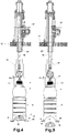
- FIG. 1 to 7 show a device 1 for carrying out the inversion of diaphragms of containers 2, such as bottles.
- Such containers 2 such as the one illustrated comprise a body 3, here cylindrical, extended above by a shoulder 4 itself surmounted by a neck 5.
- the container 2 is provided with a bottom 6 comprising a diaphragm 7, here of circular section, but being able to have other shapes allowing its reversal, contained in a ring 8 ending in a peripheral seat 9 forming a laying plane.
- the container 2 is in its configuration after manufacture by blow molding or stretch-blow molding, and the diaphragm 7 is in the general form of a bowl, the concavity of which is turned towards the interior of the container 2.
- the container 2 is cylindrical of revolution and its body 3 is reinforced by horizontal grooves 10.
- it could have a shape such as a shape more or less inscribed in a square (container or bottle called “carronde”) or any other section.
- the diaphragm would retain a rather circular section.
- the outer contour of the ring 8 would be designed to extend the shape of the body and come to die on the seat 9.
- the shoulder 4 of the container for its part, is bubble-shaped. It too could adopt any known shape (frustoconical, flute-shaped, etc.).
- the device 1 is designed to invert diaphragms 7 of filled and stoppered containers. Also, the container 2 is presented with closure means 11, such as a cap screwed onto the neck 5.
- the device 1 is carried by a frame 12 (partially shown) and comprises a lower support fifth wheel 13, fixed relative to said frame 12 (the connection between the fifth wheel 13 and the frame 12 is not shown. but is within the reach of those skilled in the art), which saddle 13 is crossed by a central orifice 14 and delimits an upper receiving plane 15, surrounding said orifice 14 to receive the seat 9 of a container.
- a pusher 16 is provided, which is movable through the central orifice 14 of the fifth wheel 13 in a vertical direction by drive means (not shown) integral with the frame 12 and the pusher 16, but comprise for example a motor electric drive.
- the drive means allow the pusher 16 to be moved from a retracted position (that of the FIG. 1 ) in which it is, for example, entirely below the upper plane of the fifth wheel 13, at a final inversion position (that of the FIG. 4 ), in which it is located above the upper plane of the saddle 12.
- the pusher 16 has an outer shape preferably corresponding to the shape of the diaphragm 7 after inversion. But the pusher 16 could have a less elaborate shape, such as, for example, that of a suitable rod.
- the device 1 also comprises an upper support member 17. As will be explained in more detail later, this support member 17 is intended to come to bear on the plugged container 2 when the latter is in place on the saddle 13 and thus counter the force of the pusher 16 when the latter is moved. towards the reverse position.
- the support member 17 consists of a bell-shaped part, which covers the stopper means 11 (and therefore the neck 5 of the container) and comes to bear on a zone of the shoulder. 4 slightly under the neck 5.
- the support member 17 could be constituted by a part simply pressing on the closure means 11.
- the bell is more advantageous, in that it generates less stress on the container 2.
- pressing on the closure means 11 generates pressure at the junction between the neck 5 and the shoulder 4, which is a zone of small section and not at all stretched, therefore fragile, while the bell presses on a larger section, so that the bearing pressure is less (for an equivalent force applied).
- the support member 17 preferably rests on the entire circumference of the shoulder. It should be noted, however, that it could include a portion of its truncated wall, so as to allow release of the bottle during the loading / unloading phases on the saddle 13, and thus limit the travel of the block 18 when the device 1 is carried on a carousel or is movable relative to a loading zone and / or an unloading zone of the containers 2.
- the support member 17 is fixed at one end, located opposite the fifth wheel 13 and the pusher 16, of a connecting block 18 connected to the frame 12 by a translational connection allowing the block to be moved vertically by relative to the saddle between a high position allowing the positioning of the container in the device and a low position in which the block 18 is held during the inversion.
- the block 18 is fixed to the end of a shaft 19 mounted to slide in the vertical direction in a sheath 20 carried by the frame 12.
- the block 18 can be brought closer to or away from the fifth wheel 13.
- the shaft 19 and therefore the block 18 are connected to a mechanism which allows an up and down movement of the shaft 19 and of the block 18 and a firm holding in the lower position of the shaft 19 and of the block 18 during the reversal and control.
- the various figures illustrate the block 18 in the low position in which it is firmly held during the inversion.
- the mechanism which allows said up and down movement of the crew formed by the shaft 19 and the block 18 is for example a cam and roller mechanism.
- the mechanism may include, above the roller 21 a first cam, called the high cam and below a second cam (again called low cam or counter cam).
- the two cams are used to guide the roller 21 for the ascent or descent of the crew formed by the shaft 19 and the block 18, the upper cam pressing on the roller and preventing the crew formed by the shaft from rising. 19 and the block 18 when a thrust is exerted from the bottom to the top under the support member 17. It would also be conceivable to have a mechanism comprising only a high cam, a roller and a lifting spring exerting a force antagonistic to that of the high cam.
- the support member 17 is fixed to the block 18 by means of elastic connection means in compression. These are arranged so that said member is itself movable in translation relative to the block 18 in a direction perpendicular to the plane of the harness and so that, in the absence of a receptacle between the harness 13 and the member 17 d 'support, the latter is in a first extreme position, low relative to the block 18, and so that, when a pressure greater than the minimum return force of the elastic connection means in compression is exerted upwards against this member 17, the latter goes up to a second extreme position, high, away from the harness 13.
- the elastic connection means in compression visible on the medallion of the FIG. 1 , are arranged as described below.
- the block 18 is hollowed out, at its end opposite the shaft 19, with a housing 22 oriented along the axis XX of the installation 1, namely an axis which passes through the center of the central orifice 14 of the harness. 13, and which coincides with that of the shaft 19, of the pusher 16, of the support member 17 and of the block 18 itself.
- the housing therefore opens in the direction of the support member 17.
- the support member 17 is fixed, at its upper part, for example by screwing, to a rod 23 which ends, at its end opposite to the support member 17, by an annular crown 24 forming a flat head surrounding this end.
- the part of the rod 23 located between the crown 24 and the support member 17 is positioned in a sleeve 25 in which it can slide freely.
- the length of this part of the rod 23 is therefore greater than the length of the sleeve 25 leaving room free to position a spring 26 working in compression around the rod 23 between the support member and the sleeve 25. If we consider the orientation of the figures, where the support member 17 is arranged under the sheath 25, the spring is therefore positioned above the support member 17 and under the sheath 25. Thus, in the absence of thrust from bottom to top (considering the orientation of the FIG.
- the spring 26 tends to maintain the support member 17 in a position away from the sleeve 25 (by pushing it down, if we still consider the orientation of the figure) and the crown 24 is then in abutment above the sleeve 25. It is important to note that the dimensions of the rod 23, of the sleeve 25 and of the spring 26 are such as to allow movement towards the top of the support member 17 when a thrust is exerted under it.
- the sleeve 25 is fitted into the housing 22, so that the crown 24 and therefore the upper end of the rod 23 are placed inside the housing 22.
- the sleeve 25 and the housing 22 are arranged so that , when the sleeve 25 is in place, there is a gap between the upper end of the rod 23 and the upper wall 27 of the housing 22, to allow the rod 23 to slide freely in the sleeve 25 when the member 17 of support is requested from bottom to top.
- the dimensions of the rod 23, of the sleeve 25 and of the spring 26 are such that in the absence of bias from the bottom upwards against the support member 17, the distance between the top of the member 17 d support and the bottom of the sheath 25 allows an upward movement of the member 17 supporting a predetermined maximum distance when a thrust is exerted from bottom to top against the support member 17.
- the distance between the upper end of the rod 23 and the upper wall 27 of the housing 22 is such that it is at least equal to the maximum distance d to allow movement of the support member 17. relative to block 18 ..
- the distance between the upper end of the rod 23 and the upper wall 27 of the housing 22 which determines the maximum distance d from the rod 23, the upper wall 27 then constituting a stop for stopping the rod. .
- the value of the spacing corresponds to the distance d .
- means such as a finger 28 are provided to prevent any rotation in the block 18 of the assembly formed by the support member 17 and the rod 23.
- the finger 28 is fixed for example by screwing into a thread 29 formed in the upper wall 27 of the housing 22 and the finger 28 passes through a hole formed in the ring 24, which prevents any rotation, but does not prevent vertical displacement of the assembly in question.
- the value of the distance between the top of the support member 17 and the bottom of the sleeve 25 or, alternatively, the value of the distance between the upper end of the rod 23 and the upper wall 27 of the housing 22 is such that the maximum distance d that the support member 17 can travel is less than 10 mm, for example between 3 mm and 8 mm. In one embodiment, for containers 2 consisting of 1 liter bottles, a stroke over a distance d of 4 mm is suitable.
- Adjustment means are provided in the device so that, when a receptacle 2, the diaphragm 7 of which must be inverted, is in place on the saddle and that the block 18 reaches the low position, the support member 17 itself comes into contact with the container 2, without pressing the latter, or even being slightly removed from it. It is indeed necessary to adapt the device 1 taking into account the dimensions of the container 2 to be treated, in particular its height.
- the setting can be made by example by modifying the position of the roller 21 on the shaft 19 and / or by modifying the position of the cam (not shown) which cooperates with the roller 21.
- the minimum return force of the compression means constituted by the spring 26 is between 100 and 300 N; in one implementation, for a 1 l bottle, it is 250 N. This minimum force is that when the spring is stretched, namely when the spring is in the position of the FIG. 1 . However, taking into account the small distance d , it will be considered hereinafter that the return force does not increase significantly when the spring is compressed to the maximum so that the term "return force" will be used whatever the position of the support member 17 relative to the block 18.
- the pusher drive means 16 are arranged so that the force applied to the pusher can vary between reversal and control.
- the force (called “inversion force”) applied to the pusher 16 may be between 400 N and 1000 N.
- the force applied to the pusher 16 is less than the return force. of the spring 26 and to the force necessary to move the diaphragm; in one implementation, the force applied to the pusher 16 during the control (called “control force”) is between 100 and 200 N; in one implementation, it is of the order of 150 N.
- a container 2 filled and stoppered beforehand is placed on the saddle 13, while the support member 17 is raised sufficiently high so as not to interfere with the stopper 11.
- the raising of the support member 17 is carried out by raising the assembly formed by the shaft 19 and the block 18 to which it is mechanically linked by the rod 23 and the sheath 25.
- the support member 17 is lowered to come into contact with the container 2, here in contact shoulder 4, without pressing it at this stage. If the support member 17 is a bell with a truncated wall portion, to allow the passage of the closure means 11 when placing the container 2 on the saddle 13, the rise is less.
- the ascent of the pusher 16 is initiated, by applying the inversion force thereto. Because the container 2 is filled and closed, it has a certain mechanical rigidity. This added to the fact that the structure of the installation is such that the inversion force is greater than that exerted by the spring 26 on the support member 17, the rise of the pusher 16 causes a rise of the container 2, of which the seat 9 moves away from the saddle 13 by going up above the upper plane 15 of the latter, and the container 2 itself pushes the support member 17 upwards, until the maximum distance has been covered. As a result, the seat 9 moves away from the upper plane 15.
- the inversion of the diaphragm 7 can begin and the extension of the container 2 also, so that when the support member 17 reaches its high position, the seat 9 can be moved away from the upper plane of the harness by a distance less than the distance d .
- FIG. 2 presents the device 1 while the support member 17 is in an intermediate position between its low position and its position in which the maximum distance d has been covered. There therefore remains a portion d int of the distance d to be covered.
- the seat 9 is slightly detached from the upper plane 15 of the harness.
- FIG. 3 when the support member 17 has traveled the maximum distance d , the seat 9 is located away from the upper plane 15 of the harness 13, at a distance from this plane.
- the value of this distance may correspond to that of the maximum distance d or be less insofar as, during the initial climb, the inversion, which is mentioned below, just as the lengthening of the container 2 could begin so that when the support member 17 reaches its upper position, the seat 9 can be moved away from the upper plane of the saddle by a distance less than the distance d . In this way, the support member 17 is in contact against the block 18 and the residual value d res of the distance is zero.
- the pusher 16 continues to rise to invert the diaphragm 7 (or finish the inversion if it started earlier when the pusher 16 is raised).
- the following phenomenon then occurs, which is the consequence of the invention.
- the deformation of the diaphragm 7 towards the interior of the container 2 causes an increase in its internal pressure which is first of all compensated for by a compression and therefore a reduction in the volume of air which remains in the neck (the head space) of the container, the liquid contained in the container 2 retaining its volume, due to its incompressibility.
- the forces generated by the pusher 16 and the support member 17 inside the container 2 become such that the container 2 is subjected to internal stresses which tend to push back its walls.
- the pusher 16 After inversion, as visible on the FIG. 5 , the pusher 16 is returned to its original position (which it occupied before inversion) and the seat 9 of the container 2 with its inverted membrane is lowered onto the upper plane 15 of the saddle 13.
- the support member 17 accompanies the movement, so that the container 2 is caught between the pusher 16 and the member 17 support until the seat 9 meets the upper plane 15 of the saddle 13. In other words, the container is guided during the entire descent phase.
- the support member 17 since the container 2 has undergone a longitudinal expansion during the inversion, when the seat 9 reaches the saddle 13, the support member 17 still exerts a certain pressure on the container 2 (more precisely on its shoulder 4), because the spring 26 is always more or less compressed.
- the support member 17 does not return to its initial position at this stage; it is found in an intermediate position, at a distance d ' int between the distances d and d res , that is to say the distances before and after inversion.
- a distance d ' int between the distances d and d res that is to say the distances before and after inversion.
- the pusher 16 is lowered to its initial position and the support member 17 is partially lowered, at a distance of int from the block 18, so that it is not up against the latter.
- the control is then carried out by raising the pusher 16, while applying to it the control force mentioned above, which is less than the return force of the spring 26 and which is such that it would not allow the rigidity of the container to be countered. and to push up a diaphragm which would have been badly inverted; preferably, the control force applied to the pusher 16 is between 100 and 200 N; in one implementation, it is of the order of 150 N.
- the pusher 16 When the pusher 16 comes to the top stop against the diaphragm 7, it stops automatically since the stresses which it then undergoes (return force of the spring and rigidity of the container) are greater; the value of the travel of the pusher 16 until it stops is then determined. Depending on whether the value is acceptable or not, the diaphragm is considered to be correctly inverted or not.
- the inversion of a diaphragm requires, during the phases illustrated by the FIG. 1 to 4 , a nominal vertical displacement of the pusher 16 of 35 mm from its original position, it may be decreed that the diaphragm is correctly reversed if the stopping of the pusher 16 during the control phase occurs at 35 mm, c ' that is, if no descent of the diaphragm, however minimal, has occurred. In such a case, it may be decreed that the diaphragm 7 is incorrectly inverted if the stop during the control phase occurs strictly before the nominal displacement is reached.
- the diaphragm is correctly formed when a variation of a few percent compared to the nominal displacement has occurred (the diaphragm is for example lowered by 2 mm, which corresponds to a stop at 33 mm during the check in the example considered). In such a case, it could be decreed that the diaphragm 7 is incorrectly inverted if the variation exceeds the permissible percentage (stopping before the pusher 16 has traveled the 33 mm in this example).
- FIG. 6 illustrates the case of a correctly inverted diaphragm 7, the pusher 16 being completely raised from its original position, illustrated in broken lines in this figure, with a height h1.
- FIG. 7 illustrates the case of an incorrectly inverted diaphragm 7, the pusher 16 only being raised from its original position, by a height h2, much less than h1 (h2 ⁇ h1).
- FIG. 8 illustrates the case of a diaphragm 7 absolutely not inverted, the pusher 16 only being raised by a few mm, the value h3 of the ascent height being even lower, since it is the one that was needed, starting from the FIG1 , to reach the diaphragm before starting to push the container upwards, then the inversion.
Landscapes
- Engineering & Computer Science (AREA)
- Mechanical Engineering (AREA)
- Manufacturing & Machinery (AREA)
- Filling Of Jars Or Cans And Processes For Cleaning And Sealing Jars (AREA)
- Sealing Of Jars (AREA)
- Auxiliary Devices For And Details Of Packaging Control (AREA)
- Labeling Devices (AREA)
- Details Of Rigid Or Semi-Rigid Containers (AREA)
- Control And Other Processes For Unpacking Of Materials (AREA)
- Closures For Containers (AREA)
- Containers And Packaging Bodies Having A Special Means To Remove Contents (AREA)
Claims (15)
- Verfahren zur Umkehrung der Membran (7) eines gefüllten und verschlossenen Behälters (2), der einen Körper (3) aufweist, der oben durch einen von einem Hals (5) überragten Ansatz (4) verlängert ist, und der in der Verlängerung des Körpers (3) nach unten einen Boden (6) aufweist, der die Membran (7) umfasst, die in einem Ring (8) enthalten ist, der in einer umlaufenden Auflagefläche (9) endet, die eine Abstellebene bildet, wobei gemäß diesem Verfahren der Behälter (2) zuvor auf einen Sattel (13) einer Umkehrvorrichtung (1) gestellt wird, ein Stützorgan (17) auf dem Behälter (2) angebracht wird und ein Schieber (16) durch den Sattel (13) hindurch nach oben bewegt wird, um die Membran (7) umzukehren und sie zu einem Gewölbe zu formen, dadurch gekennzeichnet, dass, während der Schieber (16) die Membran (7) umkehrt, die Auflagefläche (9) von der oberen Ebene (15) des Sattels (13) entfernt wird, so dass, wenn der Schieber (16) seine obere Position erreicht, ein Bereich zwischen der Auflagefläche (9) und dem Sattel (13) freigelegt wird, um eine Längsausdehnung des Behälters unter der kombinierten Wirkung der Erhöhung des Innendrucks, die durch die auf die Umkehrung zurückzuführende Verkleinerung des Volumens hervorgerufen wird, und der durch den Schieber (16) und das Stützorgan (17) im Inneren des Behälters (2) erzeugten Kräfte zu ermöglichen.
- Verfahren nach Anspruch 1, dadurch gekennzeichnet, dass es nach Durchführung der Umkehrung der Membran (7), während der Behälter (2) mit seiner Auflagefläche (9) auf dem Sattel (13) positioniert ist und das Stützorgan (17) in Anlage auf dem Behälter gehalten wird, einen Arbeitsablauf zur Kontrolle der Umkehrung einer Membran umfasst, welcher die folgenden Schritte umfasst:- die Verlagerung des Schiebers (16) aus seiner versenkten Position in seine Endposition der Umkehrung der Membran, indem auf ihn eine vorbestimmte Antriebskraft ausgeübt wird, die kleiner als eine Kraft ist, die es ermöglichen würde, eine Membran, welche schlecht umgekehrt worden ist, nach oben zurückzudrücken, so dass der Schieber (16) in das von der Membran gebildete Gewölbe eindringt und dass, wenn der Schieber mit diesem Gewölbe in Kontakt kommt, der Behälter an den Sattel angedrückt bleibt und die Bewegung des Schiebers infolge des Unterschieds der Kräfte gestoppt wird;- die Bestimmung der Position des Schiebers zu dem Zeitpunkt, zu dem er gestoppt wird, und demzufolge die Bestimmung der Amplitude der Verlagerung, die er ausgeführt hat;- den Vergleich der Amplitude der Verlagerung mit einem theoretischen Wert, welcher, falls er erreicht wird (h1), einer korrekt umgekehrten Membran und somit einem korrekt ausgebildeten Gewölbe entspricht und welcher, falls er nicht erreicht wird, einem nicht korrekt ausgebildeten (h2 < h1) oder sogar überhaupt nicht (h3) ausgebildeten Gewölbe, mit h3 < h2 <h1, entspricht.
- Vorrichtung (1) zur Durchführung des Verfahrens nach einem der Ansprüche 1 oder 2, dadurch gekennzeichnet, dass sie von einem Gestell (12) getragen wird und aufweist:- einen unteren Tragsattel (13), der in Bezug auf das Gestell (12) feststehend ist, wobei dieser Sattel von einer mittleren Öffnung (14) durchquert wird und eine Aufnahmeebene (15), welche die Öffnung (14) umgibt, zum Aufnehmen der Auflagefläche (9) eines Behälters aufweist;- einen Schieber (16), der durch mit dem Gestell fest verbundene Antriebsmittel durch die mittlere Öffnung (14) des Sattels (13) hindurch in einer vertikalen Richtung verlagerbar ist, wobei der Schieber (16) aus einer versenkten Position in eine Endposition der Umkehrung, in welcher er sich oberhalb der Ebene des Sattels befindet, verlagert werden kann;- ein oberes Stützorgan (17), das dazu bestimmt ist, auf dem verschlossenen Behälter (2) zur Anlage zu kommen, wenn dieser an seinem Platz ist, und der Kraft des Schiebers (16) entgegenzuwirken, wenn dieser Letztere zur Umkehrungsposition hin verlagert wird, wobei das Organ (17) an einem gegenüber dem Sattel (13) und dem Schieber (16) befindlichen Ende eines Verbindungsblocks (18) befestigt ist, der mit dem Gestell (12) durch eine Translationsverbindung verbunden ist, die es ermöglicht, dass der Block (18) in Bezug auf den Sattel vertikal zwischen einer hohen Position, welche die Anbringung des Behälters in der Vorrichtung ermöglicht, und einer niedrigen Position, in welcher der Block (18) während der Umkehrung gehalten wird, verlagert wird;und dadurch, dass das Stützorgan (17) an dem Ende des Blocks (18) durch Mittel (24, 25, 26) zur druckelastischen Verbindung befestigt ist, welche dafür ausgelegt sind, dass das Organ (17) selbst in Bezug auf den Block (18) in einer zur Ebene (15) des Sattels (13) senkrechten Richtung translatorisch beweglich ist, und dass bei Nichtvorhandensein eines Behälters (2) zwischen dem Sattel (13) und dem Stützorgan (17) dieses Letztere sich in einer ersten, relativ zum Block (18) niedrigen äußersten Position befindet, und dass, wenn ein Druck, der größer als die minimale Rückstellkraft der Mittel (24, 25, 26) zur druckelastischen Verbindung ist, auf dieses Organ nach oben ausgeübt wird, es sich in eine zweite, hohe äußerste Position hinaufbewegt, wobei es sich vom Sattel (13) entfernt.
- Vorrichtung (1) nach Anspruch 3, dadurch gekennzeichnet, dass der Abstand zwischen dem Stützorgan (17) und dem Sattel so groß ist, dass, wenn ein Behälter, dessen Membran (7) umgekehrt werden soll, auf dem Sattel (13) angebracht ist und der Block in die niedrige Position gelangt, das Stützorgan (17) mit dem Behälter in Kontakt kommt.
- Vorrichtung (1) nach einem der Ansprüche 3 oder 4, dadurch gekennzeichnet, dass die Antriebskraft des Schiebers (16) zwischen einem vorbestimmten Wert, der größer als die maximale Rückstellkraft der Mittel (24, 25, 26) zur druckelastischen Verbindung ist, und einem Wert, der kleiner als die minimale Rückstellkraft dieser Mittel ist, wählbar ist.
- Vorrichtung (1) nach einem der Ansprüche 3 bis 5, dadurch gekennzeichnet, dass das Stützorgan (17) dafür ausgelegt ist, an den Mitteln (11) zum Verschließen des Behälters (2) zur Anlage zu kommen.
- Vorrichtung (1) nach einem der Ansprüche 3 bis 5, dadurch gekennzeichnet, dass das Stützorgan (17) in der Form einer Glocke vorliegt, deren Abmessungen so bemessen sind, dass sie die Mittel (11) zum Verschließen des Behälters enthalten kann, und deren Umfangsrand dafür ausgelegt ist, an einem oberen Bereich des Behälters (1), wie etwa seinem Ansatz (4), zur Anlage zu kommen.
- Vorrichtung (1) nach einem der Ansprüche 3 bis 5, dadurch gekennzeichnet, dass die Mittel zur druckelastischen Verbindung, durch welche das Stützorgan an dem Ende des Blocks befestigt ist, eine Druckfeder aufweisen.
- Vorrichtung (1) nach Anspruch 8, dadurch gekennzeichnet, dass die Feder eine Metallfeder ist.
- Vorrichtung (1) nach Anspruch 8, dadurch gekennzeichnet, dass die Feder aus Elastomer besteht.
- Vorrichtung (1) nach einem der Ansprüche 3 bis 10, dadurch gekennzeichnet, dass das Stützorgan (17) einen Verlagerungsweg zwischen seiner hohen und seiner niedrige Position aufweist, der kleiner oder gleich 10 mm ist.
- Vorrichtung (1) nach Anspruch 11, dadurch gekennzeichnet, dass der Verlagerungsweg kleiner als 5 mm ist.
- Vorrichtung (1) nach einem der Ansprüche 3 bis 12, dadurch gekennzeichnet, dass der Schieber (16) eine äußere Form aufweist, die im Wesentlichen der Form der Membran (7) nach der Umkehrung entspricht.
- Verwendung der Vorrichtung (1) nach einem der Ansprüche 3 bis 13 zur Durchführung des Verfahrens zur Umkehrung einer Membran (7) nach Anspruch 1, dadurch gekennzeichnet, dass sie nacheinander die folgenden Schritte umfasst:- die Positionierung des Behälters (2) mit seiner Auflagefläche (9) auf dem Sattel (13), während sich der Schieber (16) in der versenkten Position befindet und sich der Block (18) in der hohen Position befindet;- die Verstellung des Blocks (18) in seine niedrige Position, so dass das Stützorgan (17) mit dem Behälter (2) in Kontakt kommt;- die Verlagerung des Schiebers (16) aus seiner versenkten Position in seine Endposition der Umkehrung der Membran, indem auf ihn eine vorbestimmte Antriebskraft ausgeübt wird, die größer als die maximale Rückstellkraft der Mittel zur druckelastischen Verbindung ist, so dass während der Verlagerung des Schiebers die unter dem Behälter (2) ausgeübte Kraft hervorruft:- seine Bewegung nach oben, so dass sich die Auflagefläche (9) von dem Sattel (13) entfernt, und das gleichzeitige Zusammendrücken der elastischen Mittel, so dass das Stützorgan (17) unter der Wirkung des durch die Aufwärtsbewegung des Behälters ausgeübten Schubes in seine hohe Position verlagert wird;- die Mitnahme der Membran (7) in ihre umgekehrte Position, was eine Verkleinerung des Innenvolumens des Behälters und eine Erhöhung seines Innendrucks hervorruft, mit einer infolgedessen erfolgenden Längsausdehnung des Behälters unter der Wirkung des Innendrucks und einer gleichzeitigen Annäherung der Auflagefläche (9) und des Sattels (13).
- Verwendung nach Anspruch 14, dadurch gekennzeichnet, dass sie einen Schritt der Rückkehr des Schiebers (16) in seine versenkte Position und demzufolge das Wiederabsenken des Behälters (2) auf den Sattel (13) umfasst, mit einer Aufrechterhaltung der Anlage auf dem Behälter unter der Wirkung der Mittel zur druckelastischen Verbindung.
Applications Claiming Priority (2)
| Application Number | Priority Date | Filing Date | Title |
|---|---|---|---|
| FR1762739A FR3075683B1 (fr) | 2017-12-21 | 2017-12-21 | Procede d'inversion d'un fond de recipient en matiere plastique, dispositif pour sa mise en œuvre et utilisation du dispositif |
| PCT/FR2018/053028 WO2019122563A1 (fr) | 2017-12-21 | 2018-11-28 | Procédé d'inversion d'un fond de récipient en matière plastique, dispositif pour sa mise en œuvre et utilisation du dispositif |
Publications (2)
| Publication Number | Publication Date |
|---|---|
| EP3728052A1 EP3728052A1 (de) | 2020-10-28 |
| EP3728052B1 true EP3728052B1 (de) | 2021-09-01 |
Family
ID=61750341
Family Applications (1)
| Application Number | Title | Priority Date | Filing Date |
|---|---|---|---|
| EP18829426.8A Active EP3728052B1 (de) | 2017-12-21 | 2018-11-28 | Verfahren zur umkehrung der bodenwand eines kunststoffbehälters, vorrichtung zur durchführung des verfahren und verwendung der vorrichtung zur durchführung des verfahrens |
Country Status (6)
| Country | Link |
|---|---|
| US (1) | US11505353B2 (de) |
| EP (1) | EP3728052B1 (de) |
| CN (1) | CN111491867B (de) |
| FR (1) | FR3075683B1 (de) |
| MX (1) | MX2020006097A (de) |
| WO (1) | WO2019122563A1 (de) |
Families Citing this family (2)
| Publication number | Priority date | Publication date | Assignee | Title |
|---|---|---|---|---|
| FR3091829B1 (fr) * | 2019-01-17 | 2021-02-12 | Sidel Participations | Procédé de formation d’un fond de récipient en matière plastique, comprenant une étape de contrôle de l’inversion d’un diaphragme situé au fond du récipient |
| FR3131912B1 (fr) * | 2022-01-14 | 2024-04-19 | Sidel Participations | Dispositif de retournement de fond de récipient |
Family Cites Families (11)
| Publication number | Priority date | Publication date | Assignee | Title |
|---|---|---|---|---|
| JPS525637B2 (de) * | 1974-06-05 | 1977-02-15 | ||
| US5341946A (en) | 1993-03-26 | 1994-08-30 | Hoover Universal, Inc. | Hot fill plastic container having reinforced pressure absorption panels |
| JP3143301B2 (ja) * | 1993-10-26 | 2001-03-07 | 大和製衡株式会社 | ゴミ容器反転装置 |
| TWI228476B (en) | 2000-08-31 | 2005-03-01 | Co2 Pac Ltd | Semi-rigid collapsible container |
| JP5205637B2 (ja) * | 2007-10-16 | 2013-06-05 | 北海製罐株式会社 | 合成樹脂製ボトルの底部凹入装置 |
| PL3184136T3 (pl) * | 2010-03-25 | 2022-01-17 | New Injection Systems Ltd | Wstrzykiwacz |
| CN105492369B (zh) * | 2013-09-19 | 2017-10-31 | 西德尔合作公司 | 用于处理具有可倒置隔膜的填充容器的机器和方法 |
| US11110643B2 (en) * | 2014-05-23 | 2021-09-07 | Plastipak BAWT Sá.r.l. | Heat-resistant and biaxially stretched blow-molded plastic container having a base movable to accommodate internal vacuum forces |
| EP2957522B1 (de) * | 2014-06-17 | 2017-05-03 | Sidel Participations | Behälter mit einer gekrümmten umkehrbaren Membran |
| EP3081527B1 (de) * | 2015-04-15 | 2017-07-05 | Sidel Participations | Verfahren zur herstellung einer behälterverpackung mit umgebungsfüllung und umkehrmembran |
| EP3109176A1 (de) * | 2015-06-23 | 2016-12-28 | Sidel Participations | Behälter mit einer gekrümmten umkehrbaren membran |
-
2017
- 2017-12-21 FR FR1762739A patent/FR3075683B1/fr active Active
-
2018
- 2018-11-28 MX MX2020006097A patent/MX2020006097A/es unknown
- 2018-11-28 WO PCT/FR2018/053028 patent/WO2019122563A1/fr not_active Ceased
- 2018-11-28 US US16/957,091 patent/US11505353B2/en active Active
- 2018-11-28 CN CN201880082270.8A patent/CN111491867B/zh active Active
- 2018-11-28 EP EP18829426.8A patent/EP3728052B1/de active Active
Also Published As
| Publication number | Publication date |
|---|---|
| CN111491867B (zh) | 2022-07-08 |
| CN111491867A (zh) | 2020-08-04 |
| FR3075683A1 (fr) | 2019-06-28 |
| EP3728052A1 (de) | 2020-10-28 |
| MX2020006097A (es) | 2020-08-24 |
| WO2019122563A1 (fr) | 2019-06-27 |
| US20200346809A1 (en) | 2020-11-05 |
| US11505353B2 (en) | 2022-11-22 |
| FR3075683B1 (fr) | 2019-11-22 |
Similar Documents
| Publication | Publication Date | Title |
|---|---|---|
| CA2297267C (fr) | Procede pour le remplissage de recipients, et installation pour la mise en oeuvre | |
| WO2004065105A1 (fr) | Procede et installation de fabrication d'un recipient en matiere plastique | |
| EP1250270A1 (de) | Verschlussvorrichtung und behälter | |
| EP3728052B1 (de) | Verfahren zur umkehrung der bodenwand eines kunststoffbehälters, vorrichtung zur durchführung des verfahren und verwendung der vorrichtung zur durchführung des verfahrens | |
| EP0888864A1 (de) | Vorrichtung und Verfahren zum Herstellen von einem Gegenstand aus Kunststoffmaterial | |
| CA2194544C (fr) | Dispositif d'etancheite entre une ebauche de recipient en matiere plastique et une tuyere de soufflage, et machine de soufflage de recipients pourvue d'un tel dispositif | |
| EP0167482A1 (de) | Abgabevorrichtung für Getränke, die gelöstes Gas abgeben können | |
| EP3911593A1 (de) | Verfahren zur herstellung eines bodens eines kunststoffbehälters mit einem schritt zur kontrolle der umkehrung einer am boden des behälters angeordneten membran | |
| EP4527245B1 (de) | Behälter mit rohrförmiger schürze | |
| FR2503665A1 (fr) | Perfectionnement aux flacons en matiere plastique | |
| FR2578819A1 (fr) | Verseur orientable pour bidons et recipients analogues | |
| FR2657846A1 (fr) | Dispositif pour la consommation de boissons. | |
| FR2908396A1 (fr) | Dispositif de bouchage, recipient equipe d'un tel dispositif et procede de fabrication d'un tel dispositif | |
| FR2767123A1 (fr) | Nouvelle structure de recipient et procede de conditionnement d'un produit au moyen de ce recipient | |
| FR3098524A1 (fr) | Dégorgeuse automatique en continu à carrousel | |
| EP0879179B1 (de) | Verschluss für eine flasche mit einer gashaltigen flüssigkeit | |
| WO2021053297A1 (fr) | Procédé et machine pour remplir un récipient à un niveau souhaité de liquide | |
| EP1208048B1 (de) | Verfahren zum einbau einer automatischen strohhalmausgabevorrichtung in eine blech-oder metalldose sowie die dazugehörige vorrichtung | |
| FR2599714A1 (fr) | Dispositif d'obturation d'un verre et conditionnement unitaire de boissons | |
| FR3019533A1 (fr) | Contenant pour liquide comportant une poche | |
| EP4584177A1 (de) | Druckbehälter mit verformbarer schulter und verformbarem boden | |
| EP4686670A1 (de) | Verschlussvorrichtung zum verschliessen des halses eines behälters oder eines behälters | |
| FR2606767A1 (fr) | Tete de bouchage de recipients | |
| CH348238A (fr) | Procédé pour l'emballage de produits coulables et fa#connables tels que suppositoires et dispositif pour la mise en oeuvre de ce procédé | |
| FR2648437A1 (fr) | Recipient avec un dispositif de fermeture |
Legal Events
| Date | Code | Title | Description |
|---|---|---|---|
| STAA | Information on the status of an ep patent application or granted ep patent |
Free format text: STATUS: UNKNOWN |
|
| STAA | Information on the status of an ep patent application or granted ep patent |
Free format text: STATUS: THE INTERNATIONAL PUBLICATION HAS BEEN MADE |
|
| PUAI | Public reference made under article 153(3) epc to a published international application that has entered the european phase |
Free format text: ORIGINAL CODE: 0009012 |
|
| STAA | Information on the status of an ep patent application or granted ep patent |
Free format text: STATUS: REQUEST FOR EXAMINATION WAS MADE |
|
| 17P | Request for examination filed |
Effective date: 20200612 |
|
| AK | Designated contracting states |
Kind code of ref document: A1 Designated state(s): AL AT BE BG CH CY CZ DE DK EE ES FI FR GB GR HR HU IE IS IT LI LT LU LV MC MK MT NL NO PL PT RO RS SE SI SK SM TR |
|
| AX | Request for extension of the european patent |
Extension state: BA ME |
|
| DAV | Request for validation of the european patent (deleted) | ||
| DAX | Request for extension of the european patent (deleted) | ||
| GRAP | Despatch of communication of intention to grant a patent |
Free format text: ORIGINAL CODE: EPIDOSNIGR1 |
|
| STAA | Information on the status of an ep patent application or granted ep patent |
Free format text: STATUS: GRANT OF PATENT IS INTENDED |
|
| INTG | Intention to grant announced |
Effective date: 20210526 |
|
| RIN1 | Information on inventor provided before grant (corrected) |
Inventor name: NEVEU, JEROME Inventor name: GODET, FLORIAN |
|
| GRAJ | Information related to disapproval of communication of intention to grant by the applicant or resumption of examination proceedings by the epo deleted |
Free format text: ORIGINAL CODE: EPIDOSDIGR1 |
|
| STAA | Information on the status of an ep patent application or granted ep patent |
Free format text: STATUS: REQUEST FOR EXAMINATION WAS MADE |
|
| GRAP | Despatch of communication of intention to grant a patent |
Free format text: ORIGINAL CODE: EPIDOSNIGR1 |
|
| STAA | Information on the status of an ep patent application or granted ep patent |
Free format text: STATUS: GRANT OF PATENT IS INTENDED |
|
| GRAS | Grant fee paid |
Free format text: ORIGINAL CODE: EPIDOSNIGR3 |
|
| GRAA | (expected) grant |
Free format text: ORIGINAL CODE: 0009210 |
|
| STAA | Information on the status of an ep patent application or granted ep patent |
Free format text: STATUS: THE PATENT HAS BEEN GRANTED |
|
| INTC | Intention to grant announced (deleted) | ||
| INTG | Intention to grant announced |
Effective date: 20210721 |
|
| AK | Designated contracting states |
Kind code of ref document: B1 Designated state(s): AL AT BE BG CH CY CZ DE DK EE ES FI FR GB GR HR HU IE IS IT LI LT LU LV MC MK MT NL NO PL PT RO RS SE SI SK SM TR |
|
| REG | Reference to a national code |
Ref country code: GB Ref legal event code: FG4D Free format text: NOT ENGLISH |
|
| REG | Reference to a national code |
Ref country code: CH Ref legal event code: EP Ref country code: AT Ref legal event code: REF Ref document number: 1426011 Country of ref document: AT Kind code of ref document: T Effective date: 20210915 |
|
| REG | Reference to a national code |
Ref country code: DE Ref legal event code: R096 Ref document number: 602018023038 Country of ref document: DE |
|
| REG | Reference to a national code |
Ref country code: IE Ref legal event code: FG4D Free format text: LANGUAGE OF EP DOCUMENT: FRENCH |
|
| REG | Reference to a national code |
Ref country code: LT Ref legal event code: MG9D |
|
| REG | Reference to a national code |
Ref country code: NL Ref legal event code: MP Effective date: 20210901 |
|
| PG25 | Lapsed in a contracting state [announced via postgrant information from national office to epo] |
Ref country code: RS Free format text: LAPSE BECAUSE OF FAILURE TO SUBMIT A TRANSLATION OF THE DESCRIPTION OR TO PAY THE FEE WITHIN THE PRESCRIBED TIME-LIMIT Effective date: 20210901 Ref country code: SE Free format text: LAPSE BECAUSE OF FAILURE TO SUBMIT A TRANSLATION OF THE DESCRIPTION OR TO PAY THE FEE WITHIN THE PRESCRIBED TIME-LIMIT Effective date: 20210901 Ref country code: ES Free format text: LAPSE BECAUSE OF FAILURE TO SUBMIT A TRANSLATION OF THE DESCRIPTION OR TO PAY THE FEE WITHIN THE PRESCRIBED TIME-LIMIT Effective date: 20210901 Ref country code: FI Free format text: LAPSE BECAUSE OF FAILURE TO SUBMIT A TRANSLATION OF THE DESCRIPTION OR TO PAY THE FEE WITHIN THE PRESCRIBED TIME-LIMIT Effective date: 20210901 Ref country code: BG Free format text: LAPSE BECAUSE OF FAILURE TO SUBMIT A TRANSLATION OF THE DESCRIPTION OR TO PAY THE FEE WITHIN THE PRESCRIBED TIME-LIMIT Effective date: 20211201 Ref country code: LT Free format text: LAPSE BECAUSE OF FAILURE TO SUBMIT A TRANSLATION OF THE DESCRIPTION OR TO PAY THE FEE WITHIN THE PRESCRIBED TIME-LIMIT Effective date: 20210901 Ref country code: NO Free format text: LAPSE BECAUSE OF FAILURE TO SUBMIT A TRANSLATION OF THE DESCRIPTION OR TO PAY THE FEE WITHIN THE PRESCRIBED TIME-LIMIT Effective date: 20211201 Ref country code: HR Free format text: LAPSE BECAUSE OF FAILURE TO SUBMIT A TRANSLATION OF THE DESCRIPTION OR TO PAY THE FEE WITHIN THE PRESCRIBED TIME-LIMIT Effective date: 20210901 |
|
| REG | Reference to a national code |
Ref country code: AT Ref legal event code: MK05 Ref document number: 1426011 Country of ref document: AT Kind code of ref document: T Effective date: 20210901 |
|
| PG25 | Lapsed in a contracting state [announced via postgrant information from national office to epo] |
Ref country code: PL Free format text: LAPSE BECAUSE OF FAILURE TO SUBMIT A TRANSLATION OF THE DESCRIPTION OR TO PAY THE FEE WITHIN THE PRESCRIBED TIME-LIMIT Effective date: 20210901 Ref country code: LV Free format text: LAPSE BECAUSE OF FAILURE TO SUBMIT A TRANSLATION OF THE DESCRIPTION OR TO PAY THE FEE WITHIN THE PRESCRIBED TIME-LIMIT Effective date: 20210901 Ref country code: GR Free format text: LAPSE BECAUSE OF FAILURE TO SUBMIT A TRANSLATION OF THE DESCRIPTION OR TO PAY THE FEE WITHIN THE PRESCRIBED TIME-LIMIT Effective date: 20211202 |
|
| PG25 | Lapsed in a contracting state [announced via postgrant information from national office to epo] |
Ref country code: AT Free format text: LAPSE BECAUSE OF FAILURE TO SUBMIT A TRANSLATION OF THE DESCRIPTION OR TO PAY THE FEE WITHIN THE PRESCRIBED TIME-LIMIT Effective date: 20210901 |
|
| PG25 | Lapsed in a contracting state [announced via postgrant information from national office to epo] |
Ref country code: IS Free format text: LAPSE BECAUSE OF FAILURE TO SUBMIT A TRANSLATION OF THE DESCRIPTION OR TO PAY THE FEE WITHIN THE PRESCRIBED TIME-LIMIT Effective date: 20220101 Ref country code: SM Free format text: LAPSE BECAUSE OF FAILURE TO SUBMIT A TRANSLATION OF THE DESCRIPTION OR TO PAY THE FEE WITHIN THE PRESCRIBED TIME-LIMIT Effective date: 20210901 Ref country code: SK Free format text: LAPSE BECAUSE OF FAILURE TO SUBMIT A TRANSLATION OF THE DESCRIPTION OR TO PAY THE FEE WITHIN THE PRESCRIBED TIME-LIMIT Effective date: 20210901 Ref country code: RO Free format text: LAPSE BECAUSE OF FAILURE TO SUBMIT A TRANSLATION OF THE DESCRIPTION OR TO PAY THE FEE WITHIN THE PRESCRIBED TIME-LIMIT Effective date: 20210901 Ref country code: PT Free format text: LAPSE BECAUSE OF FAILURE TO SUBMIT A TRANSLATION OF THE DESCRIPTION OR TO PAY THE FEE WITHIN THE PRESCRIBED TIME-LIMIT Effective date: 20220103 Ref country code: NL Free format text: LAPSE BECAUSE OF FAILURE TO SUBMIT A TRANSLATION OF THE DESCRIPTION OR TO PAY THE FEE WITHIN THE PRESCRIBED TIME-LIMIT Effective date: 20210901 Ref country code: EE Free format text: LAPSE BECAUSE OF FAILURE TO SUBMIT A TRANSLATION OF THE DESCRIPTION OR TO PAY THE FEE WITHIN THE PRESCRIBED TIME-LIMIT Effective date: 20210901 Ref country code: CZ Free format text: LAPSE BECAUSE OF FAILURE TO SUBMIT A TRANSLATION OF THE DESCRIPTION OR TO PAY THE FEE WITHIN THE PRESCRIBED TIME-LIMIT Effective date: 20210901 Ref country code: AL Free format text: LAPSE BECAUSE OF FAILURE TO SUBMIT A TRANSLATION OF THE DESCRIPTION OR TO PAY THE FEE WITHIN THE PRESCRIBED TIME-LIMIT Effective date: 20210901 |
|
| REG | Reference to a national code |
Ref country code: DE Ref legal event code: R097 Ref document number: 602018023038 Country of ref document: DE |
|
| PG25 | Lapsed in a contracting state [announced via postgrant information from national office to epo] |
Ref country code: MC Free format text: LAPSE BECAUSE OF FAILURE TO SUBMIT A TRANSLATION OF THE DESCRIPTION OR TO PAY THE FEE WITHIN THE PRESCRIBED TIME-LIMIT Effective date: 20210901 |
|
| PLBE | No opposition filed within time limit |
Free format text: ORIGINAL CODE: 0009261 |
|
| STAA | Information on the status of an ep patent application or granted ep patent |
Free format text: STATUS: NO OPPOSITION FILED WITHIN TIME LIMIT |
|
| REG | Reference to a national code |
Ref country code: CH Ref legal event code: PL |
|
| PG25 | Lapsed in a contracting state [announced via postgrant information from national office to epo] |
Ref country code: LU Free format text: LAPSE BECAUSE OF NON-PAYMENT OF DUE FEES Effective date: 20211128 Ref country code: DK Free format text: LAPSE BECAUSE OF FAILURE TO SUBMIT A TRANSLATION OF THE DESCRIPTION OR TO PAY THE FEE WITHIN THE PRESCRIBED TIME-LIMIT Effective date: 20210901 Ref country code: BE Free format text: LAPSE BECAUSE OF NON-PAYMENT OF DUE FEES Effective date: 20211130 |
|
| REG | Reference to a national code |
Ref country code: BE Ref legal event code: MM Effective date: 20211130 |
|
| 26N | No opposition filed |
Effective date: 20220602 |
|
| PG25 | Lapsed in a contracting state [announced via postgrant information from national office to epo] |
Ref country code: IE Free format text: LAPSE BECAUSE OF NON-PAYMENT OF DUE FEES Effective date: 20211128 |
|
| P01 | Opt-out of the competence of the unified patent court (upc) registered |
Effective date: 20230327 |
|
| PG25 | Lapsed in a contracting state [announced via postgrant information from national office to epo] |
Ref country code: CY Free format text: LAPSE BECAUSE OF FAILURE TO SUBMIT A TRANSLATION OF THE DESCRIPTION OR TO PAY THE FEE WITHIN THE PRESCRIBED TIME-LIMIT Effective date: 20210901 |
|
| GBPC | Gb: european patent ceased through non-payment of renewal fee |
Effective date: 20221128 |
|
| PG25 | Lapsed in a contracting state [announced via postgrant information from national office to epo] |
Ref country code: LI Free format text: LAPSE BECAUSE OF NON-PAYMENT OF DUE FEES Effective date: 20220701 Ref country code: HU Free format text: LAPSE BECAUSE OF FAILURE TO SUBMIT A TRANSLATION OF THE DESCRIPTION OR TO PAY THE FEE WITHIN THE PRESCRIBED TIME-LIMIT; INVALID AB INITIO Effective date: 20181128 Ref country code: CH Free format text: LAPSE BECAUSE OF NON-PAYMENT OF DUE FEES Effective date: 20220701 |
|
| PG25 | Lapsed in a contracting state [announced via postgrant information from national office to epo] |
Ref country code: SI Free format text: LAPSE BECAUSE OF FAILURE TO SUBMIT A TRANSLATION OF THE DESCRIPTION OR TO PAY THE FEE WITHIN THE PRESCRIBED TIME-LIMIT Effective date: 20210901 |
|
| PG25 | Lapsed in a contracting state [announced via postgrant information from national office to epo] |
Ref country code: GB Free format text: LAPSE BECAUSE OF NON-PAYMENT OF DUE FEES Effective date: 20221128 |
|
| PG25 | Lapsed in a contracting state [announced via postgrant information from national office to epo] |
Ref country code: MK Free format text: LAPSE BECAUSE OF FAILURE TO SUBMIT A TRANSLATION OF THE DESCRIPTION OR TO PAY THE FEE WITHIN THE PRESCRIBED TIME-LIMIT Effective date: 20210901 |
|
| PG25 | Lapsed in a contracting state [announced via postgrant information from national office to epo] |
Ref country code: MT Free format text: LAPSE BECAUSE OF FAILURE TO SUBMIT A TRANSLATION OF THE DESCRIPTION OR TO PAY THE FEE WITHIN THE PRESCRIBED TIME-LIMIT Effective date: 20210901 |
|
| PG25 | Lapsed in a contracting state [announced via postgrant information from national office to epo] |
Ref country code: TR Free format text: LAPSE BECAUSE OF FAILURE TO SUBMIT A TRANSLATION OF THE DESCRIPTION OR TO PAY THE FEE WITHIN THE PRESCRIBED TIME-LIMIT Effective date: 20210901 |
|
| PGFP | Annual fee paid to national office [announced via postgrant information from national office to epo] |
Ref country code: DE Payment date: 20251022 Year of fee payment: 8 |
|
| PGFP | Annual fee paid to national office [announced via postgrant information from national office to epo] |
Ref country code: IT Payment date: 20251022 Year of fee payment: 8 |
|
| PGFP | Annual fee paid to national office [announced via postgrant information from national office to epo] |
Ref country code: FR Payment date: 20251023 Year of fee payment: 8 |