EP3729020B1 - Schichtstruktur und herstellungsverfahren dafür - Google Patents
Schichtstruktur und herstellungsverfahren dafür Download PDFInfo
- Publication number
- EP3729020B1 EP3729020B1 EP18890165.6A EP18890165A EP3729020B1 EP 3729020 B1 EP3729020 B1 EP 3729020B1 EP 18890165 A EP18890165 A EP 18890165A EP 3729020 B1 EP3729020 B1 EP 3729020B1
- Authority
- EP
- European Patent Office
- Prior art keywords
- polymer
- layer
- sacrificial layer
- cavity
- top electrode
- Prior art date
- Legal status (The legal status is an assumption and is not a legal conclusion. Google has not performed a legal analysis and makes no representation as to the accuracy of the status listed.)
- Active
Links
Images


Classifications
-
- B—PERFORMING OPERATIONS; TRANSPORTING
- B06—GENERATING OR TRANSMITTING MECHANICAL VIBRATIONS IN GENERAL
- B06B—METHODS OR APPARATUS FOR GENERATING OR TRANSMITTING MECHANICAL VIBRATIONS OF INFRASONIC, SONIC, OR ULTRASONIC FREQUENCY, e.g. FOR PERFORMING MECHANICAL WORK IN GENERAL
- B06B1/00—Methods or apparatus for generating mechanical vibrations of infrasonic, sonic, or ultrasonic frequency
- B06B1/02—Methods or apparatus for generating mechanical vibrations of infrasonic, sonic, or ultrasonic frequency making use of electrical energy
- B06B1/0292—Electrostatic transducers, e.g. electret-type
-
- B—PERFORMING OPERATIONS; TRANSPORTING
- B32—LAYERED PRODUCTS
- B32B—LAYERED PRODUCTS, i.e. PRODUCTS BUILT-UP OF STRATA OF FLAT OR NON-FLAT, e.g. CELLULAR OR HONEYCOMB, FORM
- B32B37/00—Methods or apparatus for laminating, e.g. by curing or by ultrasonic bonding
- B32B37/02—Methods or apparatus for laminating, e.g. by curing or by ultrasonic bonding characterised by a sequence of laminating steps, e.g. by adding new layers at consecutive laminating stations
-
- B—PERFORMING OPERATIONS; TRANSPORTING
- B32—LAYERED PRODUCTS
- B32B—LAYERED PRODUCTS, i.e. PRODUCTS BUILT-UP OF STRATA OF FLAT OR NON-FLAT, e.g. CELLULAR OR HONEYCOMB, FORM
- B32B38/00—Ancillary operations in connection with laminating processes
- B32B38/10—Removing layers, or parts of layers, mechanically or chemically
-
- B—PERFORMING OPERATIONS; TRANSPORTING
- B81—MICROSTRUCTURAL TECHNOLOGY
- B81B—MICROSTRUCTURAL DEVICES OR SYSTEMS, e.g. MICROMECHANICAL DEVICES
- B81B3/00—Devices comprising flexible or deformable elements, e.g. comprising elastic tongues or membranes
- B81B3/0018—Structures acting upon the moving or flexible element for transforming energy into mechanical movement or vice versa, i.e. actuators, sensors, generators
- B81B3/0021—Transducers for transforming electrical into mechanical energy or vice versa
-
- B—PERFORMING OPERATIONS; TRANSPORTING
- B81—MICROSTRUCTURAL TECHNOLOGY
- B81C—PROCESSES OR APPARATUS SPECIALLY ADAPTED FOR THE MANUFACTURE OR TREATMENT OF MICROSTRUCTURAL DEVICES OR SYSTEMS
- B81C1/00—Manufacture or treatment of devices or systems in or on a substrate
- B81C1/00015—Manufacture or treatment of devices or systems in or on a substrate for manufacturing microsystems
- B81C1/00134—Manufacture or treatment of devices or systems in or on a substrate for manufacturing microsystems comprising flexible or deformable structures
- B81C1/00166—Electrodes
-
- G—PHYSICS
- G01—MEASURING; TESTING
- G01H—MEASUREMENT OF MECHANICAL VIBRATIONS OR ULTRASONIC, SONIC OR INFRASONIC WAVES
- G01H11/00—Measuring mechanical vibrations or ultrasonic, sonic or infrasonic waves by detecting changes in electric or magnetic properties
- G01H11/06—Measuring mechanical vibrations or ultrasonic, sonic or infrasonic waves by detecting changes in electric or magnetic properties by electric means
-
- G—PHYSICS
- G01—MEASURING; TESTING
- G01N—INVESTIGATING OR ANALYSING MATERIALS BY DETERMINING THEIR CHEMICAL OR PHYSICAL PROPERTIES
- G01N29/00—Investigating or analysing materials by the use of ultrasonic, sonic or infrasonic waves; Visualisation of the interior of objects by transmitting ultrasonic or sonic waves through the object
- G01N29/04—Analysing solids
- G01N29/06—Visualisation of the interior, e.g. acoustic microscopy
- G01N29/0654—Imaging
-
- G—PHYSICS
- G01—MEASURING; TESTING
- G01N—INVESTIGATING OR ANALYSING MATERIALS BY DETERMINING THEIR CHEMICAL OR PHYSICAL PROPERTIES
- G01N29/00—Investigating or analysing materials by the use of ultrasonic, sonic or infrasonic waves; Visualisation of the interior of objects by transmitting ultrasonic or sonic waves through the object
- G01N29/22—Details, e.g. general constructional or apparatus details
- G01N29/24—Probes
- G01N29/2406—Electrostatic or capacitive probes, e.g. electret or cMUT-probes
-
- G—PHYSICS
- G03—PHOTOGRAPHY; CINEMATOGRAPHY; ANALOGOUS TECHNIQUES USING WAVES OTHER THAN OPTICAL WAVES; ELECTROGRAPHY; HOLOGRAPHY
- G03F—PHOTOMECHANICAL PRODUCTION OF TEXTURED OR PATTERNED SURFACES, e.g. FOR PRINTING, FOR PROCESSING OF SEMICONDUCTOR DEVICES; MATERIALS THEREFOR; ORIGINALS THEREFOR; APPARATUS SPECIALLY ADAPTED THEREFOR
- G03F7/00—Photomechanical, e.g. photolithographic, production of textured or patterned surfaces, e.g. printing surfaces; Materials therefor, e.g. comprising photoresists; Apparatus specially adapted therefor
- G03F7/004—Photosensitive materials
- G03F7/039—Macromolecular compounds which are photodegradable, e.g. positive electron resists
- G03F7/0392—Macromolecular compounds which are photodegradable, e.g. positive electron resists the macromolecular compound being present in a chemically amplified positive photoresist composition
- G03F7/0395—Macromolecular compounds which are photodegradable, e.g. positive electron resists the macromolecular compound being present in a chemically amplified positive photoresist composition the macromolecular compound having a backbone with alicyclic moieties
-
- H—ELECTRICITY
- H01—ELECTRIC ELEMENTS
- H01B—CABLES; CONDUCTORS; INSULATORS; SELECTION OF MATERIALS FOR THEIR CONDUCTIVE, INSULATING OR DIELECTRIC PROPERTIES
- H01B5/00—Non-insulated conductors or conductive bodies characterised by their form
- H01B5/14—Non-insulated conductors or conductive bodies characterised by their form comprising conductive layers or films on insulating-supports
-
- H—ELECTRICITY
- H10—SEMICONDUCTOR DEVICES; ELECTRIC SOLID-STATE DEVICES NOT OTHERWISE PROVIDED FOR
- H10N—ELECTRIC SOLID-STATE DEVICES NOT OTHERWISE PROVIDED FOR
- H10N30/00—Piezoelectric or electrostrictive devices
- H10N30/01—Manufacture or treatment
- H10N30/05—Manufacture of multilayered piezoelectric or electrostrictive devices, or parts thereof, e.g. by stacking piezoelectric bodies and electrodes
-
- H—ELECTRICITY
- H10—SEMICONDUCTOR DEVICES; ELECTRIC SOLID-STATE DEVICES NOT OTHERWISE PROVIDED FOR
- H10N—ELECTRIC SOLID-STATE DEVICES NOT OTHERWISE PROVIDED FOR
- H10N30/00—Piezoelectric or electrostrictive devices
- H10N30/20—Piezoelectric or electrostrictive devices with electrical input and mechanical output, e.g. functioning as actuators or vibrators
- H10N30/204—Piezoelectric or electrostrictive devices with electrical input and mechanical output, e.g. functioning as actuators or vibrators using bending displacement, e.g. unimorph, bimorph or multimorph cantilever or membrane benders
- H10N30/2047—Membrane type
-
- H—ELECTRICITY
- H01—ELECTRIC ELEMENTS
- H01G—CAPACITORS; CAPACITORS, RECTIFIERS, DETECTORS, SWITCHING DEVICES, LIGHT-SENSITIVE OR TEMPERATURE-SENSITIVE DEVICES OF THE ELECTROLYTIC TYPE
- H01G7/00—Capacitors in which the capacitance is varied by non-mechanical means; Processes of their manufacture
Definitions
- the present disclosure is directed at methods, systems, and techniques for fabricating a layered structure, such as a capacitive micromachined ultrasound transducer, and the structure itself.
- Ultrasound imaging is the most widely used medical imaging modality in the world in terms of images created annually. Ultrasound is useful for generating images of a variety of different targets within the human body. It is important that images are acquired with high quality and in an accessible, cost-effective manner since ultrasonic imaging has many medical uses.
- the ultrasound transducer is the key hardware involved sending and receiving ultrasonic waves to and from the body. Consequently, there exists a continued need to improve the capabilities of the transducer.
- US2007013266 discloses a method of fabricating a polymer-based capacitive ultrasonic transducer, which comprises the steps of: (a) providing a substrate; (b) forming a first conductor on the substrate; (c) coating a sacrificial layer on the substrate while covering the first conductor by the same; (d) etching the sacrificial layer for forming an island while maintaining the island to contact with the first conductor; (e) coating a first polymer-based material on the substrate while covering the island by the same; (f) forming a second conductor on the first polymer-based material; (g) forming a via hole on the first polymer-based material while enabling the via hole to be channeled to the island; and (h) utilizing the via hole to etch and remove the island for forming a cavity.
- EP1955783 discloses a capacitive ultrasonic transducer including a flexible layer, a first conductive layer on the flexible layer, a support frame on the first conductive layer, the support frame including a flexible material, a membrane over the support frame being spaced apart from the first conductive layer by the support frame, the membrane including the flexible material, a cavity defined by the first conductive layer, the support frame and the membrane, and a second conductive layer on the membrane.
- ultrasonic waves emitted by a transducer travel along soft tissues, creating wave reflections (echoes) at the interfaces between tissues with different densities (e.g., fat and muscle); these echoes travel back to the transducer and are collected and processed to form an ultrasound image.
- the collection and manipulation of multiple echo signals along different directions is the basis of ultrasound image formation.
- Ultrasound transducers are a key component in an ultrasound imaging system, which transform electrical voltage into acoustic waves and vice versa.
- piezoelectric materials for their transducers since the 1930s.
- Materials such as piezoelectric crystals (e.g., quartz), ceramics (e.g., lead zirconate titanate (PZT)), and thermoplastic fluoropolymers (e.g., polyvinylidene fluoride (PVDF)) have been used as the transducer materials.
- piezoelectric crystals e.g., quartz
- ceramics e.g., lead zirconate titanate (PZT)
- thermoplastic fluoropolymers e.g., polyvinylidene fluoride (PVDF)
- PVDF polyvinylidene fluoride
- Acoustic impedance i.e., speed of sound in a material multiplied by its density, units: Rayls
- Acoustic impedance is a measure of the opposition that a system presents to the acoustic flow resulting from an acoustic pressure applied to the system. It is an important figure in piezoelectric-based ultrasound systems since it determines their acoustic efficiency, which represents how much of the acoustic power is effectively transferred to tissues.
- An acoustic matching layer is typically used in biomedical piezoelectric-based systems to reduce the impedance mismatch between the crystals and tissues (30 MRayls to 1.5 MRayls); otherwise just a fraction of the acoustic power could be used.
- These matching layers are typically made of high-density rubber combined with liquid gel and are located between the crystals and the body.
- CMUTs Capacitive micromachined ultrasound transducers
- a CMUT may be modeled as a parallel-plate capacitor with a fixed electrode at bottom, a suspended membrane over a closed cavity, and another electrode patterned on top of the cavity.
- Ultrasound waves are generated when an AC signal superimposed on a DC voltage is applied between both electrodes; conversely ultrasound waves can be detected by measuring the variation in capacitance of the device while a DC voltage is applied in the presence of incoming ultrasound waves.
- the effective distance i.e., thickness of the cavity and membrane
- the effective distance is preferably as small as possible for two reasons: 1) in order to maintain a low (e.g., less than 150 V) operating voltage during transmission (i.e., ultrasound waves generated from CMUT) and 2) to maintain a good sensitivity during reception (i.e., ultrasound waves arriving to the CMUT), since the capacitance variation is greater for large capacitance devices (i.e., those devices with comparatively thin dielectrics).
- Silicon nitride and polysilicon are the most popular materials for membranes in conventional CMUTs fabrication, while metals such as aluminum or chromium are patterned on top of the membranes to become the top electrode.
- the membrane materials are chosen mainly because of their mechanical properties so the membranes can be as thin as possible in order to minimize the effective gap between the bottom and top (or "hot") electrodes.
- the CMUT membrane By decreasing the effective gap between electrodes, the electric-field share of the gap and the capacitance increase, and the impedance matching to the electronics improves.
- the CMUT membrane should be designed to be as thick as possible given the fact that its bandwidth linearly increases with its thickness.
- CMUTs are inexpensive and can be patterned using UV light; their low density and high mechanical strength make the application of these polymers interesting in the ultrasound field mainly because acoustic impedance matching with the medium into which ultrasonic waves are sent and received can be greatly improved. Nonetheless the challenge in fabricating CMUTs using polymers is that a thick membrane with a metal electrode on top is needed to reach the MHz region, contravening the required short gap between electrodes for low operational voltages and maximum sensitivity. There has been some research in fabricating CMUTs using polymer materials; however, given their large membrane thickness the operational voltages were in the order of hundreds of volts, which is incompatible with biomedical ultrasound applications. Moreover, the mentioned devices are suitable operating in air only, and not for operating in conjunction with human tissues.
- a sacrificial layer is deposited on a substrate; the sacrificial layer is patterned into a first shape; a first polymer-based layer is deposited on the sacrificial layer; an electrode is deposited, on the first polymer-based layer, above the sacrificial layer; a second polymer-based layer is deposited on the electrode such that the electrode is between, and in some embodiments embedded, within the first and second polymer-based layers; and the sacrificial layer is then etched away to form a cavity under the electrode.
- the sacrificial layer is deposited on to a substrate assembly that functions as a bottom electrode; the sacrificial layer is patterned to be shaped as a cavity of the CMUT; the first polymer-based layer is deposited on the sacrificial layer; a via hole is patterned through the first polymer-based layer to the sacrificial layer; a top electrode is patterned, above the sacrificial layer, on the first polymer-based layer; a second polymer-based layer is deposited on the top electrode such that the top electrode is embedded within the first and second polymer-based layers; the sacrificial layer is etched away, using the via hole, to form the cavity of the CMUT; and the cavity is closed.
- wafer bonding may be used to fabricate the layered structure.
- a first polymer-based layer is deposited on a first substrate; the first polymer-based layer is patterned to be a cavity; a sacrificial layer is deposited on a second substrate; a second polymer-based layer is deposited over the sacrificial layer; an electrode is deposited on the second polymer-based layer; a third polymer-based layer is deposited on the electrode such that the electrode is between, and in some embodiments embedded, within the second and third polymer-based layers; the second and third polymer-based layers are cross-linked; the first and third polymer-based layers are adhered together such that the cavity is sealed by those layers; and the sacrificial layer is etched away such that the second polymer-based layer is released from the second substrate.
- the first polymer-based layer is deposited on the substrate assembly, which functions as the bottom electrode; the first polymer-based layer is patterned to be a cavity of the CMUT; the sacrificial layer is deposited on a separate substrate; the second polymer-based layer is deposited over the sacrificial layer; the top electrode is deposited on the second polymer-based layer; the third polymer-based layer is deposited on the top electrode such that the top electrode is embedded within the second and third polymer-based layers; the first and third polymer-based layers are adhered together such that the cavity is closed; and the sacrificial layer is etched away such that the second polymer-based layer is released from the separate substrate.
- electrodes As used herein, “embedding" an electrode with a polymer means completely covering the electrode with the polymer, except for any electrical connections made with that electrode.
- patterning a material means to selectively remove that material either directly (e.g., if it is photosensitive) or by using a masking layer (e.g., in the case of the OmniCoat TM composition, as discussed further below).
- the polymer material may be inexpensive, easy to process, and be capable of being made in large arrays.
- the top electrode is embedded within two polymer layers, with the bottom layer being thinner than the top layer; this, combined with forming a sufficiently thin CMUT cavity by etching away a sacrificial layer, permits the CMUT to reach the MHz operative region without requiring unacceptably high operating voltages.
- FIG. 1 to FIG. 18 are schematic diagrams sequentially arranged for illustrating operations comprising a method for fabricating a polymer-based CMUT according to a surface micromachining embodiment.
- FIG. 1 there is shown a cross-sectional view of a substrate assembly in the form of an electrically conductive substrate 10 (an electrically conductive silicon wafer in this case).
- a low electrical resistance of this substrate 10 facilitates the substrate 10 acting as a bottom electrode in the finished CMUT.
- a dedicated bottom electrode can be patterned over an insulating substrate 10 as an alternative.
- CMUTs are typically fabricated using silicon wafers as substrates, but any version of the rigid to semi-rigid surface with a smooth hydrophilic surface is sufficient to be used with this methodology.
- the surface of the substrate 10 is hydrophilic in at least some example embodiments in order to achieve a wet release of the final membrane described in subsequent operations.
- a sacrificial layer 11 is deposited on the substrate 10 by spin coating. This sacrificial layer 11 will become the evacuated cavity 21 in the finished CMUT.
- the required thickness of the sacrificial layer 11 for a CMUT can range from a few hundreds of nanometers (nm) (e.g., 300nm) to a couple of micrometers ( ⁇ m) (e.g., 2 ⁇ m).
- nm nanometers
- ⁇ m micrometers
- a highly selective etchant is used to etch away the sacrificial layer 11 without damaging the CMUT's membranes, which are formed in subsequent operations as described below.
- the OmniCoat TM composition by MicroChem Corp. has an excellent selectivity during etching and it enhances the adhesion of photoresists to different substrates.
- the two main chemical components in OmniCoat TM composition are cyclopentanone (a solvent that gets evaporated) and Propylene Glycol Monomethyl Ether (PGME).
- the OmniCoat TM composition also comprises a polymer (less than 1% of total volume) and a surfactant (also less than 1% of total volume).
- the OmniCoat TM composition is not photosensitive and its typical thickness during spin coating ranges from 5nm to 15nm, which limits its conventional use to releasing large structures by immersing them in developer for a few hours until the structures get released and float away from the carrying substrate.
- the OmniCoat TM composition is used for the sacrificial layer 11.
- the OmniCoat TM composition is evaporated prior to depositing it as the sacrificial layer 11. For example, evaporating a certain percentage of the solvents of the off-the-shelf OmniCoat TM composition (e.g., 85%) prior to its deposition allows a relatively thick sacrificial layer 11 (e.g., 0.3 ⁇ m), to be deposited in a single step.
- the OmniCoat TM composition may not be evaporated at all prior to its deposition as the sacrificial layer 11; for example, without any pre-deposition evaporation, multiple layers of the OmniCoat TM composition may be deposited in order to reach a desired thickness.
- a certain proportion of its solvents may be evaporated, that proportion may be more or less than 85%.
- a thinner sacrificial layer 11 is desired, then a smaller percentage (e.g., 70%) of the solvents in the OmniCoat TM composition may be evaporated; alternatively, more (e.g., 90%) of the solvents may be evaporated. More generally, this pre-deposition evaporation may be performed on whatever composition is used as the sacrificial layer 11.
- the sacrificial layer 11 is patterned to create the areas that will become the cavity 21 (shown in FIG. 15 ) in the final device as well as releasing channels to permit access to this cavity 21.
- the OmniCoat TM composition is not photosensitive it cannot be directly patterned and needs to be removed indirectly.
- a layer of positive photoresist (PR) 12 is deposited on top of the sacrificial layer 11.
- This photoresist (S 1813) is selected so that its developer dissolves the cross-linked photoresist 13 (shown in FIG. 3 ), which results after ultraviolet light (UV) exposure as well as the sacrificial material 11.
- the photoresist layer 12 is exposed to UV using a photomask and a mask aligner.
- the areas exposed to UV become cross-linked photoresist 13 and the areas not exposed to UV are left intact (uncross-linked).
- the cross-linked photoresist 13 is etched away (removed) by placing the sample in an aqueous solution containing an alkaline-based photoresist developer (MF319).
- MF319 alkaline-based photoresist developer
- the etching continues and starts dissolving the sacrificial layer 11.
- the patterned photoresist layer 12 acts as a masking layer to protect the sacrificial layer 11 underneath.
- the etching is stopped as soon as the sacrificial layer 11 under the cross-linked photoresist 13 is removed, leaving the substrate 10 exposed for subsequent operations.
- the masking layer of positive photoresist 12 is removed by immersing the sample in acetone or any other solvent suitable to dissolve the positive PR 12 without damaging the sacrificial layer 11.
- the sacrificial layer 11 offers an excellent selectivity (chemical resistance) to the solvent used (acetone). What is left behind is a patterned sacrificial layer 11 containing the areas that will become the cavity 21 in the final device as well as the etch channels.
- a first polymer-based layer 14 comprising a negative photosensitive polymer-based material (SU8 photoresist, hereinafter interchangeably referred to simply as "SU8") 14 is deposited, conformally covering the sacrificial layer 11.
- the thickness of the layer 14 is designed to be as thin as possible to conformally coat the sacrificial layer 11 and to be able to maintain good electrical insulation between the conductive substrate 10, which acts at the finished CMUT's bottom electrode, and a top electrode 16 (shown in FIGS. 10-15 ).
- the SU8 comprises Bisphenol A Novolac epoxy dissolved in an organic solvent, and comprises up to 10 wt% Triarylsulfonium/hexafluoroantimonate salt; in different example embodiments (not depicted), the polymer-based material may have a different composition.
- the SU8 is also optically transparent, which facilitates inspection of the finished device.
- a material may be used in place of the SU8, and that replacement material may be non-opaque (i.e., partially or entirely transparent).
- the layer 14 in at least the depicted example embodiment comprises a photopolymer.
- Photopolymers are inexpensive and can be patterned using UV; their low density and high mechanical strength make the application of these polymers interesting in the ultrasound field mainly because the impedance matching with the medium into which ultrasonic waves are transmitted and from which reflected waves are received can be greatly improved. Nonetheless the challenge in fabricating CMUTs using polymers is that, conventionally, a thick membrane with a metal electrode on top is needed to reach the MHz operational region, contravening the required short gap between electrodes that facilitate low operational voltages and maximum sensitivity.
- the layer 14 is exposed to UV using a photomask and a mask aligner.
- the areas exposed to UV light become cross-linked areas 15 of the layer 14 and the areas not exposed to UV are left as uncross-linked areas.
- the uncross-linked areas of the first polymer-based layer 14 are etched away (removed) by placing the sample in an aqueous solution containing a negative photoresist developer (SU8 developer).
- SU8 developer negative photoresist developer
- an electrically conductive top electrode (chromium) 16 is patterned on top of the cross-linked areas 15 of the first polymer-based layer 14 using lift-off methods.
- This electrode 16 is in at least some example embodiments made as thin as possible without sacrificing electrical conductivity in order to not greatly modify the structural properties of the cross-linked areas 15, which will later become the membrane of the finished device.
- the material for this electrode 16 in at least the depicted example embodiment is typically metallic; nevertheless any other material capable of fulfilling the functions of the top electrode 16 can be used (e.g., conductive polymers, optically transparent materials, etc.).
- a good adhesion between this top electrode 16 and the cross-linked areas 15 is present in order to avoid any potential delamination during normal operation of the finished device.
- Using chromium as the top electrode 16 when the cross-linked areas 15 comprise SU8 may help to facilitate adhesion.
- the overall thickness of the membrane i.e., the cross-linked areas 15 and the top electrode 16
- its resonant frequency would be just a fraction of the desired operational frequency in the finished device.
- a much thicker membrane is required in order to reach the desired operational frequency in, for example, the MHz range.
- a second polymer-based layer 17 is deposited over the membrane, conformally coating the sacrificial layer 11, the first polymer-based layer 15, and the top electrode 16.
- the second polymer-based layer 17 is of the same photosensitive polymer (SU8) as the first polymer-based layer 14 in at least the depicted example embodiment; however, in different embodiments (not depicted) the layers 14,17 may comprise different polymers.
- the thickness of this second polymer-based layer 17 is designed to be a few times ( ⁇ 5) thicker than that of the cross-linked areas 15 of the first polymer-based layer 14.
- the second polymer-based layer 17 is exposed to UV using a photomask and a mask aligner.
- the areas exposed to UV light become cross-linked areas 18 and the areas not exposed to UV are left intact (uncross-linked).
- the uncross-linked areas of the second polymer-based layer 17 are etched away (removed) by placing the sample in an aqueous solution containing a negative photoresist developer (SU8 developer).
- SU8 developer negative photoresist developer
- the top electrode 16 becomes embedded between the cross-linked areas 15,18 of the two polymer-based layers 14,17.
- the advantage of this approach is that the membrane is still able to operate in the MHz region because of the added thickness from the second polymer-based layer 17, which increases the effective stiffness while still maintaining a low operational voltage thanks to the small effective distance between the bottom substrate 10 and the embedded top electrode 16.
- This fabrication process is not limited to the operation in the MHz range for biomedical ultrasound imaging. If desired, the same or an analogous fabrication process can be used to obtain membranes that operate in the Hz and kHz region for air-coupled operation applications, for example.
- the final operational frequency of the membrane depends on the geometry of the cell. This means that membranes that resonate at different frequencies can be operated with very similar voltages. For example, two membranes with the same diameter can operate with the same voltage (same effective distance between electrodes), but one can be thinner for lower frequencies and the other ticker for high-frequency operation.
- the sample is then immersed in an aqueous alkaline-based solution containing the etchant (MF319) of the sacrificial layer 11.
- MF319 etchant
- the patterned sacrificial layer 11 is gradually removed though via holes and etch channels until it is fully dissolved.
- the etchant is replaced by water and then by isopropanol (IPA).
- IPA isopropanol
- the sample is encapsulated by a bio-compatible material 20 (a poly(p-xylylene) polymer, such as parylene) inside a low-pressure chamber; while various pressures may be used, in the depicted example embodiment the pressure within the chamber is 1 ⁇ 10 -3 Torr.
- the encapsulating material 20 conformally coats the entire sample, sealing the via holes and etch channels to form a closed cavity 21.
- the cavity 21 is vacuum sealed and is watertight and airtight, which helps to avoid squeeze-film effects and to reduce the risk of voltage breakdown.
- the cavity 21 may not be vacuum sealed, or may be watertight and not airtight.
- the fabrication process is complete and the finished device (i.e., the CMUT) results.
- the biocompatible material parylene
- the biocompatible material is an excellent electrical insulator and is safe for use on humans.
- This fabrication process may use optically transparent or semi-transparent materials for any one or more of the substrate (e.g. glass or quartz), for the electrodes (e.g. Indium oxide, which is semi-transparent) and for the sealing layer (parylene). This leads to an optically transparent or semi-transparent transducer.
- the substrate e.g. glass or quartz
- the electrodes e.g. Indium oxide, which is semi-transparent
- the sealing layer parylene
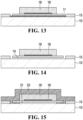
- FIG. 16 depicts an example CMUT in which the electrode 16 is located above the second polymer-based layer 18 and then encapsulated by the encapsulating material 20.
- the operating voltage of the CMUT of FIG. 15 is much lower than that of FIG. 16 .
- the resonant frequency of the membranes in FIG. 15 and FIG. 16 is the same since all the materials and thickness remain the same except for the location of the top electrode.
- the operational voltage of the CMUT shown in FIG. 15 is 50 Volts, whereas the operational voltage of the CMUT shown in FIG. 16 is 300 Volts, which is prohibitive in medical ultrasound systems.
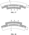
- FIGS. 1-15 may be used to fabricate the CMUT on flexible substrates. This is an advantage for conformal imaging systems in which the ultrasound elements are to be curved around different parts of the human body as depicted in FIG. 17 and FIG. 18 .
- the polymer materials used for fabrication are sufficiently flexible, allowing the CMUT to bend around small radii of curvature without sacrificing performance or mechanical stability.
- CMUTs fabricated with polysilicon and silicon nitride are generally inflexible and employ hazardous chemicals (potassium hydroxide and hydrochloric acid) during etching.
- hazardous chemicals potassium hydroxide and hydrochloric acid
- the chemicals may present a risk for people working with these materials as they are corrosive and the vapours can cause internal organ damage, resulting in severe and in some cases fatal consequences.
- the fabrication operations according to at least some of the example embodiments herein can be performed in simple low-cost and safe fabrication facility.
- the aforementioned fabrication process in at least some example embodiments employ non-hazardous materials, i.e. only organic solvents are used during fabrication (acetone, isopropanol, SU8 developer, and positive photoresist developer).
- non-hazardous materials i.e. only organic solvents are used during fabrication (acetone, isopropanol, SU8 developer, and positive photoresist developer).
- the health risks associated with an accidental prolonged exposure to these materials are generally limited to drowsiness and minor skin irritation.
- the etchant used to remove the OmniCoat TM composition MF319 or Tetramethylammonium hydroxide diluted in water
- the fabrication costs associated with the fabrication process depicted in FIGS. 1-15 is significantly less than the cost required to manufacture conventional designs. As of December, 2017, the estimated material costs to fabricate an array of ultrasound transducers is less than US$100 inside a university laboratory, with a potential cost reduction if mass produced; meaning that the fabricated devices can be considered at some point disposable.
- the maximum temperature required to manufacture CMUTs using the described process in FIGS. 1-15 for this process is 150°C, consequently requiring minimal thermal protection systems and using minimal thermal budget compared to conventional fabrication processes using polysilicon.
- CMUTs using polymers as structural material for CMUTs means that if an acoustic matching layer is required it can be manufactured using the same kind of polymer materials with embedded fillers.
- FIGS. 32-37 there are depicted perspective views sequentially arranged for illustrating operations comprising a method for fabricating a polymer-based CMUT, according to another example embodiment.
- the electrically-conductive substrate 10 e.g., silicon wafer
- a sacrificial material e.g., the OmniCoat TM composition
- a layer of positive photoresist (S1813) is deposited on top of the OmniCoat TM composition and baked.
- the sample is selectively exposed to UV to pattern the sacrificial layer 11's design.
- the sample is immersed in positive photoresist developer (MF319).
- the developer dissolves both unexposed areas in S1813 and the OmniCoat TM composition underneath, thereby leaving a patterned design of the sacrificial layer 11.
- the sacrificial layer 11 comprises an area to eventually form the CMUT cavity 21 as well as etch channels 37 and etch via holes 35.
- the sample coated with the first polymer-based layer 14 comprising a polymer-based material (SU8), conformally covering the sacrificial layer 11.
- the thickness of the layer 14 is by design selected to be as thin as possible as long as the sacrificial layer 14 is covered and the breakdown voltage of the polymer exceeds the desired operational voltage.
- the sample is exposed to UV to pattern the anchor points of the sample as well as the first layer of the membrane.
- the sample is baked and developed in SU8 developer, leaving open windows for the etch channels 37.
- the electrically conductive electrode 16 (chromium) is patterned on top of the first polymer-based layer 14 using lift-off micromachining methods; electrical connections 39 to the electrode 16 are concurrently patterned.
- the thickness of the electrode 16 is as thin as possible as long as a low resistance path is maintained.
- the electrode 16 may comprise non-metallic materials, such as one or more conductive polymers.
- the second polymer-based layer 17 is conformally coated on top of the electrode 16, covering the stack comprising the sacrificial layer 11, first polymer-based layer 14, and metal electrode 16.
- the second polymer-based layer 17 also comprises the SU8.
- the sample is exposed to UV to pattern the CMUT membrane and leave open areas for the via holes 35 on the first polymer-based layer 14.
- the purpose of this second polymer-based layer 17 is to increase the effective thickness of the membrane and therefore increase its resonant frequency. Electrical contacts are exposed to air.
- the sample is immersed in positive photoresist developer (MF319, same etching chemical as for the OmniCoat TM composition). Developer removes the sacrificial material through the via holes 35 and etch channels 37.
- the developer (MF319) is replaced by water and then by isopropyl alcohol (IPA) in a wet environment.
- the sample is immersed in IPA inside a critical point dryer system to release the membrane. Liquid CO 2 replaces IPA in a highpressure environment and then the liquid CO 2 is converted to gaseous CO 2 . At this point the membrane is suspended on the cavity 19. While a critical point system is used in the fabrication depicted in FIGS. 32-37 , in different embodiments (not depicted) it may be omitted, particularly if the CMUT membrane is not prone to stiction given its dimensions.
- the sample is placed in a low-pressure chamber (e.g., operated at 1 ⁇ 10 -3 Torr) and conformally coated with the encapsulating material 20 comprising polymer materials (parylene) so that the cavity 21 is vacuum-sealed (i.e., airtight) and watertight.
- a low-pressure chamber e.g., operated at 1 ⁇ 10 -3 Torr
- the encapsulating material 20 comprising polymer materials (parylene) so that the cavity 21 is vacuum-sealed (i.e., airtight) and watertight.
- the parylene's thickness is selected so the mechanical properties of the encapsulating material 20 in the finished CMUT are very similar (and in some embodiments identical) to the SU8 (e.g., in terms of density and Young's modulus); accordingly, in at least some embodiments the collective thickness of the encapsulating material 20 and the second polymer-based layer 17 are considered when comparing that thickness to that of the first polymer-based layer 15, the ratio of which influences the finished CMUT's operational frequency.
- the encapsulating material 20 seals the via holes 35 and etch channels 37, leaving a vacuum-sealed and watertight cavity once the sample is removed from the low-pressure chamber. Areas for electrical interconnections are protected prior this sealing step.
- the resulting finished CMUT is a sealed CMUT element with a low pull-in voltage given its small effective separation between electrodes.
- the carrying substrate need not be limited to rigid materials; flexible material temporarily attached to a rigid carrier may be used as well.
- the sample may be electrically interconnected to an interface circuit prior to sealing ( FIG. 36 ). An acceptable adhesion between polymer material and electrode is used to avoid mechanical failure during operation.
- wafer bonding technology can be used to manufacture a similar version of the CMUT depicted in FIG 15 .
- the materials are deposited and processed in two separate substrates, such as silicon wafers.
- the materials deposited on the separate substrates are then adhered together and further processed to obtain CMUTs.
- the detailed fabrication description follows.
- the first polymer-based layer 14 comprising a polymer-based material (SU8) is deposited on top of a substrate assembly comprising the bottom substrate 10, which acts as the bottom electrode in the finished CMUT and which in the depicted example embodiment is electrically conductive.
- a substrate assembly comprising the bottom substrate 10, which acts as the bottom electrode in the finished CMUT and which in the depicted example embodiment is electrically conductive.
- the first polymer-based layer 14 is exposed to UV using a photomask.
- the areas exposed to UV become the cross-linked areas 15 and the areas not exposed to UV are left uncross-linked.
- the uncross-linked areas of the first polymer-based layer 14 are etched away (removed) using photoresist developer (SU8 developer).
- the cross-linked areas 15 remain intact.
- the cross-linked areas 15 that remain following etching will act as pillars supporting the CMUT membranes.
- a sacrificial layer 11 is deposited on top by spin coating. This sacrificial layer 11 will be used to release the separate substrate 30 following adhering, as discussed further below.
- the second polymer-based layer 17, which in the depicted example embodiment comprises the same photosensitive polymer (SU8) as used for the first polymer-based layer 14, is deposited on top of the sacrificial layer 11; this layer 17 will become the top part of the finished CMUT.
- SU8 photosensitive polymer
- the second polymer-based layer 17 is exposed to UV using a photomask and a mask aligner.
- the areas exposed to UV become the cross-linked areas 18.
- the electrically conductive top electrode 16 (chromium) is patterned on top of the cross-linked areas 18 using lift-off methods.
- a third polymer-based layer 32 of the same photosensitive polymer (SU8) comprising the first and second polymer-based layers 14,17 is deposited on the top electrodes 16, conformally coating the metal electrodes 16 and the cross-linked areas 18 of the second polymer-based layer 17.
- the top electrode 16 becomes encapsulated between the cross-linked areas 18 of the second polymer-based layer 17 and the third polymer-based layer 32.
- the third polymer-based layer 32 is exposed to UV using a photomask and a mask aligner.
- the areas exposed to UV become cross-linked areas 33.
- the purpose of the cross-linked areas 33 is to act as dielectric layer between the two electrodes (the bottom substrate 10 and the top electrode 16) in the finished CMUT.
- Cross-linking the first and third polymer-based layers 14,32 serves to promote adhesion between those layers; in at least some different example embodiments (not depicted), the cross-linking may be skipped if the layers 14,32 can be suitably adhered to each other without cross-linking.
- the surfaces of the separate samples as shown in FIG. 21 and FIG. 27 are treated with oxygen plasma, which allows the surfaces of both samples to be permanently adhered.
- the samples are aligned and placed face to face in a vacuum environment and pressed against each other.
- the vacuum may be any suitable pressure, such as 1 ⁇ 10 -3 Torr as described above in the surface micromachining embodiment.
- the samples may not be treated with oxygen plasma.
- the sample is immersed in an aqueous alkaline-based solution containing the etchant (MF319) of the sacrificial layer 11.
- MF319 etchant
- the sacrificial layer 11 is gradually removed until the separate substrate 30 is released.
- This etchant does not attack the polymer not the metallic materials used.
- the fabrication process is complete and the device becomes watertight.
- the cavities 21, while closed may not be airtight or watertight; in other embodiments, the cavities 21 may be watertight and not airtight.
- the CMUT fabricated using wafer bonding does not comprise the encapsulating material 20 in the depicted example embodiments as the cavities 21 are vacuum-sealed following adhesion. This simplifies fabrication.
- the fill factor (number of CMUTs per unit area) may be improved using wafer bonding vs. surface micromachining, as the CMUTs can be placed closer to each another since the releasing holes (vias) and channels do not exist.
- the fill factor can be increased, relative to circular membranes.
- Roll-to-Roll (R2R) technology may be applied to fabricate the cavity 21.
- one or both of the substrates 10,30 may be flexible if bonded to a rigid carrier.
- Charge trapping effects in CMUTs may be observed, for example, when a zero-bias resonator is fabricated by purposely trapping electrical charges in a dielectric layer by applying a large bias voltage beyond pull-in. More generally, charge trappings effects may be observed for any resonator (including a CMUT) or layered device fabricated according to the embodiments described herein, including those that are not zero-bias. In the examples described herein, the trapped charging effect contributes positive to the normal operation of the resonator (e.g., a materially lower operational voltage may be used when trapped charges are present).
- This causes the membrane to collapse (e.g., to be pulled into contact with the substrate 10), resulting in the electrical field acting on the membrane to increase.
- the cavity 21 is sufficiently tall that the membrane does not contact the bottom substrate 10 when the DC voltage is applied.
- the membrane After removing the DC voltage, the membrane returns to its initial position having electrical charges 22 trapped in the dielectric film (SU8).
- the electrical charges 22 trapped in the membrane contribute to the electrostatic force during operation (acting like a built-in voltage), meaning that a lower DC bias voltage may be used to bring the membrane closer to the bottom substrate 10.
- CMUT elements a set of linear arrays containing 64 and 128 CMUT elements, with each element comprising an interconnected matrix of CMUT cells sharing a common bottom electrode in the form of a conductive substrate 10 (a silicon wafer), were fabricated. These CMUT elements are shown in FIG. 38 (64 elements) and FIG. 39 (128 elements). The total fabrication time was 16 Hrs.
- FIG. 40 and FIG. 41 Detailed views of the fabricated arrays are shown in FIG. 40 and FIG. 41 for a 64 and 128 element array, respectively.
- the diameter of the CMUT cells is 100 ⁇ m and 90 ⁇ m for the 64 and 128 element arrays, respectively.
- the thickness of the CMUT membranes is 7.31 ⁇ m, which includes the top electrode 16 and the cross-linked areas 15 of the first polymer-based layer 14 and the vacuum-filled cavity 21 has a height of 0.3 ⁇ m. Electrical connections for external interface are located at each end on the elements.
- FIG. 44 shows the measurement of an ultrasound pulse generated by a piezoelectric crystal located above a polymer CMUT element in a liquid medium operating at an acoustic pressure typical for medical ultrasound imaging.
- the terminals of the CMUT top and bottom electrode were directly connected to an oscilloscope.
- the amplitude of the received signal when the CMUTs are operated as a passive device was 264 mVpp; this represents much more than the expected voltage obtained from typical piezoelectric-based transducers, in which the expected generated voltage across the terminals ranges between a few microvolts and 100 mV.
- the amplitude of the received signals was increased even further to almost 500 mVpp when a bias voltage of 15V was applied.
- ultrasound signals can be directly processed without the need of low-noise and high-gain amplifiers used in commercial piezoelectric-based ultrasound systems, potentially reducing the physical volume and weight in ultrasound probes and marking a step forward towards a lightweight, low-power conformal ultrasound system.
- no acoustic matching layer is required to couple the fabricated CMUTs (regardless of whether fabricated using surface micromachining or wafer bonding) to an aqueous medium. This contrasts with the mandatory acoustic matching layer in conventional piezoelectric-based ultrasound imaging systems.
- one or both of the surface micromachining and wafer bonding embodiments may further comprise an annealing operation.
- annealing may be done at, for example, 150°C for five minutes to anneal any cracks that may have formed during development.
- Coupled and variants of it such as “coupled”, “couples”, and “coupling” as used in this description are intended to include indirect and direct connections unless otherwise indicated. For example, if a first device is coupled to a second device, that coupling may be through a direct connection or through an indirect connection via other devices and connections. Similarly, if the first device is communicatively coupled to the second device, communication may be through a direct connection or through an indirect connection via other devices and connections.
Landscapes
- Physics & Mathematics (AREA)
- Engineering & Computer Science (AREA)
- General Physics & Mathematics (AREA)
- Chemical & Material Sciences (AREA)
- Analytical Chemistry (AREA)
- Biochemistry (AREA)
- General Health & Medical Sciences (AREA)
- Life Sciences & Earth Sciences (AREA)
- Immunology (AREA)
- Pathology (AREA)
- Health & Medical Sciences (AREA)
- Manufacturing & Machinery (AREA)
- Microelectronics & Electronic Packaging (AREA)
- Spectroscopy & Molecular Physics (AREA)
- Mechanical Engineering (AREA)
- Acoustics & Sound (AREA)
- Computer Hardware Design (AREA)
- Micromachines (AREA)
- Transducers For Ultrasonic Waves (AREA)
- Measurement Of Mechanical Vibrations Or Ultrasonic Waves (AREA)
- Laminated Bodies (AREA)
- Ultra Sonic Daignosis Equipment (AREA)
Claims (15)
- Verfahren zum Herstellen einer Schichtstruktur, das Verfahren umfassend:(a) Abscheiden einer Opferschicht (11) auf einer Substratanordnung (10), die als untere Elektrode fungiert;(b) Strukturieren der Opferschicht in eine erste Form;(c) Abscheiden einer ersten Schicht auf Polymerbasis (14) auf der strukturierten Opferschicht;(d) Strukturieren einer oberen Elektrode (16) auf der ersten Schicht auf Polymerbasis oberhalb der strukturierten Opferschicht;(e) Abscheiden einer zweiten Schicht auf Polymerbasis (17) auf der oberen Elektrode, sodass die obere Elektrode zwischen der ersten und der zweiten Schicht auf Polymerbasis ist, wobei die zweite Schicht auf Polymerbasis mindestens fünfmal stärker ist als die erste Schicht auf Polymerbasis; und(f) nachdem die zweite Schicht auf Polymerbasis auf der oberen Elektrode abgeschieden worden ist, Wegätzen der strukturierten Opferschicht, um einen Hohlraum (21) unter der oberen Elektrode zu bilden.
- Verfahren nach Anspruch 1, wobei die erste Form einen Kanal umfasst, die sich durch die erste Schicht auf Polymerbasis erstreckt und es dem Ätzmittel ermöglicht, von der Oberseite der ersten Schicht auf Polymerbasis zu der strukturierten Opferschicht zu fließen.
- Verfahren nach Anspruch 2, wobei die zweite Schicht auf Polymerbasis abgeschieden wird, um den Kanal zu blockieren, und ferner umfassend ein Wegätzen eines Teils der zweiten Schicht auf Polymerbasis, der den Kanal blockiert, wobei ein Wegätzen der strukturierten Opferschicht das Fließen des Ätzmittels durch den Kanal umfasst.
- Verfahren nach Anspruch 1, ferner umfassend Schließen des Hohlraums, sodass eine wasserdichte Dichtung um den Hohlraum herum gebildet wird.
- Verfahren nach Anspruch 1, wobei die Opferschicht lichtempfindlich ist und wobei ein Strukturieren der Opferschicht zum Bildung des Hohlraums Folgendes umfasst:(a) Vernetzen eines Teils der Opferschicht, die als die erste Form geformt ist; und(b) Anwenden eines Entwicklers, um einen Teil der Opferschicht, der nicht vernetzt ist, wegzuätzen.
- Verfahren nach Anspruch 1, wobei die Opferschicht nicht lichtempfindlich ist und wobei ein Strukturieren der Opferschicht zum Bildung des Hohlraums Folgendes umfasst:(a) Abscheiden einer positiven Photoresistschicht (12) auf der Opferschicht;(b) Vernetzen eines Teils (13) der positiven Photoresistschicht, der einem Teil der Opferschicht entspricht, der als Hohlraum geformt ist;(c) Anwenden eines Photoresistentwicklers, um die nicht vernetzte Photoresistschicht und die Opferschicht, die unter der nicht vernetzten Photoresistschicht liegt, wegzuätzen; und(d) nachdem die Photoresistschicht und die Opferschicht weggeätzt worden sind, Entfernen der vernetzten Photoresistschicht.
- Verfahren nach Anspruch 1, wobei die Substratanordnung flexibel ist.
- Verfahren nach Anspruch 1, wobei die obere Elektrode ein leitendes Polymer umfasst.
- Verfahren nach Anspruch 1, wobei die Substratanordnung ein optisch transparentes Material umfasst.
- Verfahren nach Anspruch 1, wobei die Substratanordnung ein nichtleitendes Substrat und eine leitende untere Elektrode auf einem Substrat umfasst.
- Verfahren nach Anspruch 1, wobei die Schichtstruktur einen kapazitiven mikrobearbeiteten Ultraschallwandler umfasst, die erste Form einen Hohlraum des Wandlers umfasst und ferner Folgendes umfasst:(a) Strukturieren eines Durchgangslochs durch die erste Schicht auf Polymerbasis zu der Opferschicht; und wobei das Ätzen unter Verwendung des Durchgangslochs durchgeführt wird, um den Hohlraum zu bilden; und(b) Schließen des Hohlraums.
- Verfahren nach Anspruch 11, wobei ein Schließen des Hohlraums in einer Polymerverdampferkammer bei einem Druck von nicht mehr als 0,001 Torr erfolgt.
- Verfahren nach Anspruch 11, wobei die obere Elektrode in die erste und die zweite Schicht auf Polymerbasis eingebettet ist.
- Verfahren nach Anspruch 1, wobei eine Stärke der zweiten Schicht auf Polymerbasis im Verhältnis zu einer Stärke der ersten Schicht auf Polymerbasis gewählt ist, sodass die obere Elektrode mit einer Frequenz von mindestens 1 MHz schwingt.
- Schichtstruktur, gefertigt gemäß dem Verfahren nach einem der Ansprüche 1 bis 14.
Priority Applications (1)
| Application Number | Priority Date | Filing Date | Title |
|---|---|---|---|
| EP24193742.4A EP4478014A1 (de) | 2017-12-19 | 2018-12-18 | Schichtstruktur und herstellungsverfahren dafür |
Applications Claiming Priority (2)
| Application Number | Priority Date | Filing Date | Title |
|---|---|---|---|
| US201762607641P | 2017-12-19 | 2017-12-19 | |
| PCT/CA2018/051618 WO2019119127A1 (en) | 2017-12-19 | 2018-12-18 | Layered structure and method for fabricating same |
Related Child Applications (2)
| Application Number | Title | Priority Date | Filing Date |
|---|---|---|---|
| EP24193742.4A Division EP4478014A1 (de) | 2017-12-19 | 2018-12-18 | Schichtstruktur und herstellungsverfahren dafür |
| EP24193742.4A Division-Into EP4478014A1 (de) | 2017-12-19 | 2018-12-18 | Schichtstruktur und herstellungsverfahren dafür |
Publications (3)
| Publication Number | Publication Date |
|---|---|
| EP3729020A1 EP3729020A1 (de) | 2020-10-28 |
| EP3729020A4 EP3729020A4 (de) | 2022-04-13 |
| EP3729020B1 true EP3729020B1 (de) | 2024-09-18 |
Family
ID=66992395
Family Applications (2)
| Application Number | Title | Priority Date | Filing Date |
|---|---|---|---|
| EP24193742.4A Pending EP4478014A1 (de) | 2017-12-19 | 2018-12-18 | Schichtstruktur und herstellungsverfahren dafür |
| EP18890165.6A Active EP3729020B1 (de) | 2017-12-19 | 2018-12-18 | Schichtstruktur und herstellungsverfahren dafür |
Family Applications Before (1)
| Application Number | Title | Priority Date | Filing Date |
|---|---|---|---|
| EP24193742.4A Pending EP4478014A1 (de) | 2017-12-19 | 2018-12-18 | Schichtstruktur und herstellungsverfahren dafür |
Country Status (7)
| Country | Link |
|---|---|
| US (3) | US10509013B2 (de) |
| EP (2) | EP4478014A1 (de) |
| JP (1) | JP7278287B2 (de) |
| KR (1) | KR102833282B1 (de) |
| CN (1) | CN111742199B (de) |
| CA (1) | CA3085014A1 (de) |
| WO (1) | WO2019119127A1 (de) |
Families Citing this family (12)
| Publication number | Priority date | Publication date | Assignee | Title |
|---|---|---|---|---|
| IT201700050174A1 (it) * | 2017-05-09 | 2018-11-09 | Leonardo Spa | Dispositivo per ispezione non distruttiva basato su grafene e relativo metodo |
| JP7278287B2 (ja) * | 2017-12-19 | 2023-05-19 | ザ ユニヴァーシティ オブ ブリティッシュ コロンビア | 層状構造及び層状構造を製造するための方法 |
| EP3815795A1 (de) * | 2019-10-30 | 2021-05-05 | Nederlandse Organisatie voor toegepast- natuurwetenschappelijk Onderzoek TNO | Membranwandler mit verbesserter bandbreite |
| KR20210080685A (ko) * | 2019-12-20 | 2021-07-01 | 삼성디스플레이 주식회사 | 표시 장치 및 표시 장치의 제조 방법 |
| CN115398183A (zh) * | 2020-01-17 | 2022-11-25 | 大不列颠哥伦比亚大学 | 柔性电容式微加工超声换能器阵列 |
| KR102298213B1 (ko) * | 2020-01-31 | 2021-09-06 | 한국과학기술원 | 다층 구조의 멤브레인을 가진 초음파 트랜스듀서 및 이의 제작 방법 |
| US20230363735A1 (en) | 2020-10-02 | 2023-11-16 | The University Of British Columbia | Contactless cmut operation |
| TWI819775B (zh) * | 2021-10-13 | 2023-10-21 | 台亞半導體股份有限公司 | 矽化物電容式微機電結構及其製造方法 |
| EP4554892A4 (de) * | 2022-07-13 | 2025-10-15 | Univ British Columbia | Hochgeschwindigkeitsherstellung von arrays mikroelektrischer mechanischer systeme |
| CN116833079A (zh) * | 2023-06-30 | 2023-10-03 | 京东方科技集团股份有限公司 | 电容式微机械超声换能器 |
| CN117544127B (zh) * | 2023-11-21 | 2024-07-09 | 武汉敏声新技术有限公司 | 一种体声波谐振器及其制备方法 |
| CN119533639A (zh) * | 2024-11-08 | 2025-02-28 | 合肥领航微系统集成有限公司 | 一种基于有机聚合物结构的超声波传感器及制备方法 |
Family Cites Families (45)
| Publication number | Priority date | Publication date | Assignee | Title |
|---|---|---|---|---|
| JPS5277411A (en) * | 1975-12-22 | 1977-06-29 | Marugo Kk | Horizontal sheet pile type continuous underground wall construction method |
| US5281635A (en) | 1991-05-17 | 1994-01-25 | Johnson Matthey Public Limited Company | Precious metal composition |
| US7898722B2 (en) * | 1995-05-01 | 2011-03-01 | Qualcomm Mems Technologies, Inc. | Microelectromechanical device with restoring electrode |
| US6443901B1 (en) | 2000-06-15 | 2002-09-03 | Koninklijke Philips Electronics N.V. | Capacitive micromachined ultrasonic transducers |
| JP2004518319A (ja) * | 2001-01-05 | 2004-06-17 | アー.ヤー. アンゲルセン、ビョルン | 広帯域トランスデューサ |
| US6827250B2 (en) | 2001-06-28 | 2004-12-07 | Microchips, Inc. | Methods for hermetically sealing microchip reservoir devices |
| CA2493389A1 (en) * | 2001-08-28 | 2003-03-06 | Scott Ballantyne | Electromagnetic piezoelectric acoustic sensor |
| CA2406684A1 (en) * | 2001-10-05 | 2003-04-05 | Queen's University At Kingston | Ultrasound transducer array |
| US6808953B2 (en) | 2002-12-31 | 2004-10-26 | Robert Bosch Gmbh | Gap tuning for surface micromachined structures in an epitaxial reactor |
| US20050121734A1 (en) * | 2003-11-07 | 2005-06-09 | Georgia Tech Research Corporation | Combination catheter devices, methods, and systems |
| US20050177045A1 (en) * | 2004-02-06 | 2005-08-11 | Georgia Tech Research Corporation | cMUT devices and fabrication methods |
| TWI260940B (en) * | 2005-06-17 | 2006-08-21 | Ind Tech Res Inst | Method for producing polymeric capacitive ultrasonic transducer |
| WO2006123300A2 (en) * | 2005-05-18 | 2006-11-23 | Kolo Technologies, Inc. | Micro-electro-mechanical transducers |
| CN101558552B (zh) | 2005-06-17 | 2017-05-31 | 科隆科技公司 | 具有绝缘延伸部的微机电换能器 |
| EP2495212A3 (de) | 2005-07-22 | 2012-10-31 | QUALCOMM MEMS Technologies, Inc. | MEMS-Vorrichtungen mit Stützstrukturen und Herstellungsverfahren dafür |
| JP4676988B2 (ja) * | 2005-09-05 | 2011-04-27 | 株式会社日立メディコ | 超音波撮像装置 |
| US7561009B2 (en) * | 2005-11-30 | 2009-07-14 | Avago Technologies General Ip (Singapore) Pte. Ltd. | Film bulk acoustic resonator (FBAR) devices with temperature compensation |
| US7643203B2 (en) | 2006-04-10 | 2010-01-05 | Qualcomm Mems Technologies, Inc. | Interferometric optical display system with broadband characteristics |
| US7721397B2 (en) * | 2007-02-07 | 2010-05-25 | Industrial Technology Research Institute | Method for fabricating capacitive ultrasonic transducers |
| US8178004B2 (en) * | 2008-06-27 | 2012-05-15 | Aculon, Inc. | Compositions for providing hydrophobic layers to metallic substrates |
| FR2933390B1 (fr) * | 2008-07-01 | 2010-09-03 | Commissariat Energie Atomique | Procede d'encapsulation d'un dispositif microelectronique par un materiau getter |
| US8146425B2 (en) * | 2008-09-05 | 2012-04-03 | Analog Devices, Inc. | MEMS sensor with movable z-axis sensing element |
| US8939029B2 (en) * | 2008-09-05 | 2015-01-27 | Analog Devices, Inc. | MEMS sensor with movable Z-axis sensing element |
| US8821009B2 (en) * | 2009-12-23 | 2014-09-02 | Intel Corporation | Thermal sensors having flexible substrates and use thereof |
| JP2011244425A (ja) * | 2010-04-23 | 2011-12-01 | Canon Inc | 電気機械変換装置及びその作製方法 |
| FR2963099B1 (fr) | 2010-07-22 | 2013-10-04 | Commissariat Energie Atomique | Capteur de pression dynamique mems, en particulier pour des applications a la realisation de microphones |
| EP2460762B1 (de) * | 2010-12-06 | 2014-10-08 | Nxp B.V. | MEMS-Vorrichtung mit verringerter Haftung und Herstellungsverfahren |
| CN102249181A (zh) * | 2011-03-28 | 2011-11-23 | 大连理工大学 | 一种su-8胶微力传感器的制作方法 |
| US9085456B2 (en) | 2012-01-16 | 2015-07-21 | Taiwan Semiconductor Manufacturing Company, Ltd. | Support structure for TSV in MEMS structure |
| US9210516B2 (en) * | 2012-04-23 | 2015-12-08 | Infineon Technologies Ag | Packaged MEMS device and method of calibrating a packaged MEMS device |
| US20130293482A1 (en) * | 2012-05-04 | 2013-11-07 | Qualcomm Mems Technologies, Inc. | Transparent through-glass via |
| WO2014008358A1 (en) | 2012-07-05 | 2014-01-09 | Cornell University | Porous membrane apparatus, method, and applications |
| US9925561B2 (en) * | 2013-03-05 | 2018-03-27 | The University Of Manitoba | Capacitive micromachined ultrasonic transducer with multiple deflectable membranes |
| JP5807664B2 (ja) * | 2013-08-07 | 2015-11-10 | 横河電機株式会社 | 振動式トランスデューサおよびその製造方法 |
| US9517929B2 (en) * | 2013-11-19 | 2016-12-13 | Rofin-Sinar Technologies Inc. | Method of fabricating electromechanical microchips with a burst ultrafast laser pulses |
| CA2948355A1 (en) * | 2014-05-08 | 2015-11-12 | Bart Lipkens | Acoustophoretic device with piezoelectric transducer array |
| US9921004B2 (en) * | 2014-09-15 | 2018-03-20 | Kelvin Thermal Technologies, Inc. | Polymer-based microfabricated thermal ground plane |
| JP6813149B2 (ja) | 2015-03-13 | 2021-01-13 | 国立大学法人豊橋技術科学大学 | 物理・化学センサ、物理・化学現象センシングデバイスおよびこれらの使用方法ならびに物理・化学センサアレイ |
| US10427188B2 (en) * | 2015-07-30 | 2019-10-01 | North Carolina State University | Anodically bonded vacuum-sealed capacitive micromachined ultrasonic transducer (CMUT) |
| JP6561804B2 (ja) | 2015-12-03 | 2019-08-21 | 三菱電機株式会社 | 半導体装置の製造方法 |
| CN105413997B (zh) | 2015-12-09 | 2017-11-07 | 华南理工大学 | 柔性化电容式微加工超声换能器及其制备方法 |
| WO2017186781A1 (en) * | 2016-04-26 | 2017-11-02 | Koninklijke Philips N.V. | Ultrasound device contacting |
| US11529120B2 (en) | 2016-04-26 | 2022-12-20 | Koninklijke Philips N.V. | Ultrasound device contacting |
| CN106517081B (zh) * | 2016-10-28 | 2018-03-09 | 中国科学院深圳先进技术研究院 | 磁性封装微机器人及其制备方法 |
| JP7278287B2 (ja) * | 2017-12-19 | 2023-05-19 | ザ ユニヴァーシティ オブ ブリティッシュ コロンビア | 層状構造及び層状構造を製造するための方法 |
-
2018
- 2018-12-18 JP JP2020533239A patent/JP7278287B2/ja active Active
- 2018-12-18 EP EP24193742.4A patent/EP4478014A1/de active Pending
- 2018-12-18 CA CA3085014A patent/CA3085014A1/en active Pending
- 2018-12-18 KR KR1020207020260A patent/KR102833282B1/ko active Active
- 2018-12-18 CN CN201880089581.7A patent/CN111742199B/zh active Active
- 2018-12-18 EP EP18890165.6A patent/EP3729020B1/de active Active
- 2018-12-18 WO PCT/CA2018/051618 patent/WO2019119127A1/en not_active Ceased
-
2019
- 2019-02-14 US US16/276,548 patent/US10509013B2/en active Active
- 2019-02-14 US US16/276,517 patent/US10564132B2/en active Active
- 2019-11-14 US US16/684,543 patent/US10598632B1/en active Active
Also Published As
| Publication number | Publication date |
|---|---|
| EP3729020A1 (de) | 2020-10-28 |
| WO2019119127A1 (en) | 2019-06-27 |
| CA3085014A1 (en) | 2019-06-27 |
| KR20200100112A (ko) | 2020-08-25 |
| JP2021506603A (ja) | 2021-02-22 |
| KR102833282B1 (ko) | 2025-07-11 |
| US20200080971A1 (en) | 2020-03-12 |
| EP4478014A1 (de) | 2024-12-18 |
| US10598632B1 (en) | 2020-03-24 |
| CN111742199B (zh) | 2023-01-06 |
| US20190187102A1 (en) | 2019-06-20 |
| JP7278287B2 (ja) | 2023-05-19 |
| CN111742199A (zh) | 2020-10-02 |
| US10564132B2 (en) | 2020-02-18 |
| EP3729020A4 (de) | 2022-04-13 |
| US20190187101A1 (en) | 2019-06-20 |
| US10509013B2 (en) | 2019-12-17 |
Similar Documents
| Publication | Publication Date | Title |
|---|---|---|
| EP3729020B1 (de) | Schichtstruktur und herstellungsverfahren dafür | |
| US10864553B2 (en) | Piezoelectric transducers and methods of making and using the same | |
| Gerardo et al. | Fabrication and testing of polymer-based capacitive micromachined ultrasound transducers for medical imaging | |
| US20170170383A1 (en) | Curved Piezoelectric Transducers and Methods of Making and Using the Same | |
| TWI260940B (en) | Method for producing polymeric capacitive ultrasonic transducer | |
| EP3037178B1 (de) | Kapazitiver mikrobearbeiteter ultraschallwandler und testobjekterfassungsvorrichtung mit kapazitivem mikrobearbeitetem ultraschallwandler | |
| US20050177045A1 (en) | cMUT devices and fabrication methods | |
| CN107812691B (zh) | 压电超声换能器及其制备方法 | |
| US20110062535A1 (en) | Mems transducers | |
| WO2007134051A2 (en) | High frequency ultrasound transducers | |
| TW200930122A (en) | Electromechanical transducer and manufacturing method therefor | |
| US20150183634A1 (en) | Capacitive transducer and method of manufacturing the same | |
| Wang et al. | Highly sensitive piezoelectric micromachined ultrasonic transducer operated in air | |
| Manwar et al. | Manufacturing process of optically transparent ultrasound transducer: A review | |
| CN107511317B (zh) | 压电超声换能器及其制备方法 | |
| US8536665B2 (en) | Fabrication of piezoelectric single crystalline thin layer on silicon wafer | |
| Salowitz et al. | Screen printed piezoceramic actuators/sensors microfabricated on organic films and stretchable networks | |
| Joshi et al. | Fabrication of high-frequency 2D flexible pMUT array | |
| Sleva et al. | A micromachined poly (vinylidene fluoride-trifluoroethylene) transducer for pulse-echo ultrasound applications | |
| Chang et al. | 6F-6 a novel method for fabricating sonic paper | |
| Joshi et al. | Bendable polymer-based high-frequency PMUTs on transparent SU8 and polyimide substrates | |
| Stoeckel et al. | Design and technology for uniform aluminum nitride piezoelectric micromachined ultrasonic transducers with radial array | |
| CN210609703U (zh) | 一种mems结构 | |
| Shi et al. | A novel stretchable CMUT array using liquid-metal electrodes on a PDMS substrate | |
| Ren et al. | Micromachined piezoelectric acoustic device |
Legal Events
| Date | Code | Title | Description |
|---|---|---|---|
| STAA | Information on the status of an ep patent application or granted ep patent |
Free format text: STATUS: THE INTERNATIONAL PUBLICATION HAS BEEN MADE |
|
| PUAI | Public reference made under article 153(3) epc to a published international application that has entered the european phase |
Free format text: ORIGINAL CODE: 0009012 |
|
| STAA | Information on the status of an ep patent application or granted ep patent |
Free format text: STATUS: REQUEST FOR EXAMINATION WAS MADE |
|
| 17P | Request for examination filed |
Effective date: 20200714 |
|
| AK | Designated contracting states |
Kind code of ref document: A1 Designated state(s): AL AT BE BG CH CY CZ DE DK EE ES FI FR GB GR HR HU IE IS IT LI LT LU LV MC MK MT NL NO PL PT RO RS SE SI SK SM TR |
|
| AX | Request for extension of the european patent |
Extension state: BA ME |
|
| DAV | Request for validation of the european patent (deleted) | ||
| DAX | Request for extension of the european patent (deleted) | ||
| RIC1 | Information provided on ipc code assigned before grant |
Ipc: G01N 29/24 20060101ALI20211105BHEP Ipc: G01N 29/06 20060101ALI20211105BHEP Ipc: B81C 1/00 20060101ALI20211105BHEP Ipc: B06B 1/02 20060101ALI20211105BHEP Ipc: G03F 7/30 20060101ALI20211105BHEP Ipc: H01L 49/00 20060101ALI20211105BHEP Ipc: H01G 7/00 20060101ALI20211105BHEP Ipc: B32B 38/10 20060101ALI20211105BHEP Ipc: B32B 37/02 20060101ALI20211105BHEP Ipc: B32B 27/00 20060101ALI20211105BHEP Ipc: A61B 8/00 20060101ALI20211105BHEP Ipc: G01H 11/06 20060101AFI20211105BHEP |
|
| A4 | Supplementary search report drawn up and despatched |
Effective date: 20220311 |
|
| RIC1 | Information provided on ipc code assigned before grant |
Ipc: G01N 29/24 20060101ALI20220305BHEP Ipc: G01N 29/06 20060101ALI20220305BHEP Ipc: B81C 1/00 20060101ALI20220305BHEP Ipc: B06B 1/02 20060101ALI20220305BHEP Ipc: G03F 7/30 20060101ALI20220305BHEP Ipc: H01L 49/00 20060101ALI20220305BHEP Ipc: H01G 7/00 20060101ALI20220305BHEP Ipc: B32B 38/10 20060101ALI20220305BHEP Ipc: B32B 37/02 20060101ALI20220305BHEP Ipc: B32B 27/00 20060101ALI20220305BHEP Ipc: A61B 8/00 20060101ALI20220305BHEP Ipc: G01H 11/06 20060101AFI20220305BHEP |
|
| RIC1 | Information provided on ipc code assigned before grant |
Ipc: B32B 37/02 20060101ALI20240118BHEP Ipc: H01G 7/00 20060101ALI20240118BHEP Ipc: G01N 29/24 20060101ALI20240118BHEP Ipc: G01N 29/06 20060101ALI20240118BHEP Ipc: B81C 1/00 20060101ALI20240118BHEP Ipc: B32B 38/10 20060101ALI20240118BHEP Ipc: B06B 1/02 20060101ALI20240118BHEP Ipc: G01H 11/06 20060101AFI20240118BHEP |
|
| GRAP | Despatch of communication of intention to grant a patent |
Free format text: ORIGINAL CODE: EPIDOSNIGR1 |
|
| STAA | Information on the status of an ep patent application or granted ep patent |
Free format text: STATUS: GRANT OF PATENT IS INTENDED |
|
| INTG | Intention to grant announced |
Effective date: 20240408 |
|
| GRAS | Grant fee paid |
Free format text: ORIGINAL CODE: EPIDOSNIGR3 |
|
| GRAA | (expected) grant |
Free format text: ORIGINAL CODE: 0009210 |
|
| STAA | Information on the status of an ep patent application or granted ep patent |
Free format text: STATUS: THE PATENT HAS BEEN GRANTED |
|
| P01 | Opt-out of the competence of the unified patent court (upc) registered |
Free format text: CASE NUMBER: APP_43656/2024 Effective date: 20240726 |
|
| AK | Designated contracting states |
Kind code of ref document: B1 Designated state(s): AL AT BE BG CH CY CZ DE DK EE ES FI FR GB GR HR HU IE IS IT LI LT LU LV MC MK MT NL NO PL PT RO RS SE SI SK SM TR |
|
| REG | Reference to a national code |
Ref country code: GB Ref legal event code: FG4D |
|
| REG | Reference to a national code |
Ref country code: CH Ref legal event code: EP |
|
| REG | Reference to a national code |
Ref country code: NL Ref legal event code: FP Ref country code: IE Ref legal event code: FG4D |
|
| REG | Reference to a national code |
Ref country code: DE Ref legal event code: R096 Ref document number: 602018074605 Country of ref document: DE |
|
| REG | Reference to a national code |
Ref country code: LT Ref legal event code: MG9D |
|
| PG25 | Lapsed in a contracting state [announced via postgrant information from national office to epo] |
Ref country code: NO Free format text: LAPSE BECAUSE OF FAILURE TO SUBMIT A TRANSLATION OF THE DESCRIPTION OR TO PAY THE FEE WITHIN THE PRESCRIBED TIME-LIMIT Effective date: 20241218 |
|
| PG25 | Lapsed in a contracting state [announced via postgrant information from national office to epo] |
Ref country code: GR Free format text: LAPSE BECAUSE OF FAILURE TO SUBMIT A TRANSLATION OF THE DESCRIPTION OR TO PAY THE FEE WITHIN THE PRESCRIBED TIME-LIMIT Effective date: 20241219 Ref country code: FI Free format text: LAPSE BECAUSE OF FAILURE TO SUBMIT A TRANSLATION OF THE DESCRIPTION OR TO PAY THE FEE WITHIN THE PRESCRIBED TIME-LIMIT Effective date: 20240918 |
|
| PG25 | Lapsed in a contracting state [announced via postgrant information from national office to epo] |
Ref country code: BG Free format text: LAPSE BECAUSE OF FAILURE TO SUBMIT A TRANSLATION OF THE DESCRIPTION OR TO PAY THE FEE WITHIN THE PRESCRIBED TIME-LIMIT Effective date: 20240918 |
|
| PG25 | Lapsed in a contracting state [announced via postgrant information from national office to epo] |
Ref country code: LV Free format text: LAPSE BECAUSE OF FAILURE TO SUBMIT A TRANSLATION OF THE DESCRIPTION OR TO PAY THE FEE WITHIN THE PRESCRIBED TIME-LIMIT Effective date: 20240918 |
|
| PG25 | Lapsed in a contracting state [announced via postgrant information from national office to epo] |
Ref country code: HR Free format text: LAPSE BECAUSE OF FAILURE TO SUBMIT A TRANSLATION OF THE DESCRIPTION OR TO PAY THE FEE WITHIN THE PRESCRIBED TIME-LIMIT Effective date: 20240918 |
|
| PG25 | Lapsed in a contracting state [announced via postgrant information from national office to epo] |
Ref country code: RS Free format text: LAPSE BECAUSE OF FAILURE TO SUBMIT A TRANSLATION OF THE DESCRIPTION OR TO PAY THE FEE WITHIN THE PRESCRIBED TIME-LIMIT Effective date: 20241218 |
|
| PG25 | Lapsed in a contracting state [announced via postgrant information from national office to epo] |
Ref country code: RS Free format text: LAPSE BECAUSE OF FAILURE TO SUBMIT A TRANSLATION OF THE DESCRIPTION OR TO PAY THE FEE WITHIN THE PRESCRIBED TIME-LIMIT Effective date: 20241218 Ref country code: NO Free format text: LAPSE BECAUSE OF FAILURE TO SUBMIT A TRANSLATION OF THE DESCRIPTION OR TO PAY THE FEE WITHIN THE PRESCRIBED TIME-LIMIT Effective date: 20241218 Ref country code: LV Free format text: LAPSE BECAUSE OF FAILURE TO SUBMIT A TRANSLATION OF THE DESCRIPTION OR TO PAY THE FEE WITHIN THE PRESCRIBED TIME-LIMIT Effective date: 20240918 Ref country code: HR Free format text: LAPSE BECAUSE OF FAILURE TO SUBMIT A TRANSLATION OF THE DESCRIPTION OR TO PAY THE FEE WITHIN THE PRESCRIBED TIME-LIMIT Effective date: 20240918 Ref country code: GR Free format text: LAPSE BECAUSE OF FAILURE TO SUBMIT A TRANSLATION OF THE DESCRIPTION OR TO PAY THE FEE WITHIN THE PRESCRIBED TIME-LIMIT Effective date: 20241219 Ref country code: FI Free format text: LAPSE BECAUSE OF FAILURE TO SUBMIT A TRANSLATION OF THE DESCRIPTION OR TO PAY THE FEE WITHIN THE PRESCRIBED TIME-LIMIT Effective date: 20240918 Ref country code: BG Free format text: LAPSE BECAUSE OF FAILURE TO SUBMIT A TRANSLATION OF THE DESCRIPTION OR TO PAY THE FEE WITHIN THE PRESCRIBED TIME-LIMIT Effective date: 20240918 |
|
| REG | Reference to a national code |
Ref country code: AT Ref legal event code: MK05 Ref document number: 1725069 Country of ref document: AT Kind code of ref document: T Effective date: 20240918 |
|
| PG25 | Lapsed in a contracting state [announced via postgrant information from national office to epo] |
Ref country code: PT Free format text: LAPSE BECAUSE OF FAILURE TO SUBMIT A TRANSLATION OF THE DESCRIPTION OR TO PAY THE FEE WITHIN THE PRESCRIBED TIME-LIMIT Effective date: 20250120 Ref country code: IS Free format text: LAPSE BECAUSE OF FAILURE TO SUBMIT A TRANSLATION OF THE DESCRIPTION OR TO PAY THE FEE WITHIN THE PRESCRIBED TIME-LIMIT Effective date: 20250118 |
|
| PG25 | Lapsed in a contracting state [announced via postgrant information from national office to epo] |
Ref country code: RO Free format text: LAPSE BECAUSE OF FAILURE TO SUBMIT A TRANSLATION OF THE DESCRIPTION OR TO PAY THE FEE WITHIN THE PRESCRIBED TIME-LIMIT Effective date: 20240918 Ref country code: SM Free format text: LAPSE BECAUSE OF FAILURE TO SUBMIT A TRANSLATION OF THE DESCRIPTION OR TO PAY THE FEE WITHIN THE PRESCRIBED TIME-LIMIT Effective date: 20240918 |
|
| PG25 | Lapsed in a contracting state [announced via postgrant information from national office to epo] |
Ref country code: ES Free format text: LAPSE BECAUSE OF FAILURE TO SUBMIT A TRANSLATION OF THE DESCRIPTION OR TO PAY THE FEE WITHIN THE PRESCRIBED TIME-LIMIT Effective date: 20240918 |
|
| PG25 | Lapsed in a contracting state [announced via postgrant information from national office to epo] |
Ref country code: AT Free format text: LAPSE BECAUSE OF FAILURE TO SUBMIT A TRANSLATION OF THE DESCRIPTION OR TO PAY THE FEE WITHIN THE PRESCRIBED TIME-LIMIT Effective date: 20240918 Ref country code: EE Free format text: LAPSE BECAUSE OF FAILURE TO SUBMIT A TRANSLATION OF THE DESCRIPTION OR TO PAY THE FEE WITHIN THE PRESCRIBED TIME-LIMIT Effective date: 20240918 |
|
| PG25 | Lapsed in a contracting state [announced via postgrant information from national office to epo] |
Ref country code: CZ Free format text: LAPSE BECAUSE OF FAILURE TO SUBMIT A TRANSLATION OF THE DESCRIPTION OR TO PAY THE FEE WITHIN THE PRESCRIBED TIME-LIMIT Effective date: 20240918 Ref country code: PL Free format text: LAPSE BECAUSE OF FAILURE TO SUBMIT A TRANSLATION OF THE DESCRIPTION OR TO PAY THE FEE WITHIN THE PRESCRIBED TIME-LIMIT Effective date: 20240918 |
|
| PG25 | Lapsed in a contracting state [announced via postgrant information from national office to epo] |
Ref country code: IT Free format text: LAPSE BECAUSE OF FAILURE TO SUBMIT A TRANSLATION OF THE DESCRIPTION OR TO PAY THE FEE WITHIN THE PRESCRIBED TIME-LIMIT Effective date: 20240918 Ref country code: SK Free format text: LAPSE BECAUSE OF FAILURE TO SUBMIT A TRANSLATION OF THE DESCRIPTION OR TO PAY THE FEE WITHIN THE PRESCRIBED TIME-LIMIT Effective date: 20240918 |
|
| REG | Reference to a national code |
Ref country code: DE Ref legal event code: R097 Ref document number: 602018074605 Country of ref document: DE |
|
| PG25 | Lapsed in a contracting state [announced via postgrant information from national office to epo] |
Ref country code: MC Free format text: LAPSE BECAUSE OF FAILURE TO SUBMIT A TRANSLATION OF THE DESCRIPTION OR TO PAY THE FEE WITHIN THE PRESCRIBED TIME-LIMIT Effective date: 20240918 |
|
| PG25 | Lapsed in a contracting state [announced via postgrant information from national office to epo] |
Ref country code: DK Free format text: LAPSE BECAUSE OF FAILURE TO SUBMIT A TRANSLATION OF THE DESCRIPTION OR TO PAY THE FEE WITHIN THE PRESCRIBED TIME-LIMIT Effective date: 20240918 |
|
| PLBE | No opposition filed within time limit |
Free format text: ORIGINAL CODE: 0009261 |
|
| STAA | Information on the status of an ep patent application or granted ep patent |
Free format text: STATUS: NO OPPOSITION FILED WITHIN TIME LIMIT |
|
| REG | Reference to a national code |
Ref country code: CH Ref legal event code: PL |
|
| PG25 | Lapsed in a contracting state [announced via postgrant information from national office to epo] |
Ref country code: LU Free format text: LAPSE BECAUSE OF NON-PAYMENT OF DUE FEES Effective date: 20241218 |
|
| 26N | No opposition filed |
Effective date: 20250619 |
|
| PG25 | Lapsed in a contracting state [announced via postgrant information from national office to epo] |
Ref country code: SE Free format text: LAPSE BECAUSE OF FAILURE TO SUBMIT A TRANSLATION OF THE DESCRIPTION OR TO PAY THE FEE WITHIN THE PRESCRIBED TIME-LIMIT Effective date: 20240918 |
|
| REG | Reference to a national code |
Ref country code: BE Ref legal event code: MM Effective date: 20241231 |
|
| PG25 | Lapsed in a contracting state [announced via postgrant information from national office to epo] |
Ref country code: BE Free format text: LAPSE BECAUSE OF NON-PAYMENT OF DUE FEES Effective date: 20241231 |
|
| PG25 | Lapsed in a contracting state [announced via postgrant information from national office to epo] |
Ref country code: CH Free format text: LAPSE BECAUSE OF NON-PAYMENT OF DUE FEES Effective date: 20241231 |
|
| PG25 | Lapsed in a contracting state [announced via postgrant information from national office to epo] |
Ref country code: IE Free format text: LAPSE BECAUSE OF NON-PAYMENT OF DUE FEES Effective date: 20241218 |
|
| PGFP | Annual fee paid to national office [announced via postgrant information from national office to epo] |
Ref country code: NL Payment date: 20251003 Year of fee payment: 8 |
|
| PGFP | Annual fee paid to national office [announced via postgrant information from national office to epo] |
Ref country code: DE Payment date: 20250930 Year of fee payment: 8 |
|
| PGFP | Annual fee paid to national office [announced via postgrant information from national office to epo] |
Ref country code: GB Payment date: 20251001 Year of fee payment: 8 |
|
| PGFP | Annual fee paid to national office [announced via postgrant information from national office to epo] |
Ref country code: FR Payment date: 20251008 Year of fee payment: 8 |