EP3729059B1 - Système de détection de biomarqueurs avec capteur spr implantable - Google Patents
Système de détection de biomarqueurs avec capteur spr implantable Download PDFInfo
- Publication number
- EP3729059B1 EP3729059B1 EP18892718.0A EP18892718A EP3729059B1 EP 3729059 B1 EP3729059 B1 EP 3729059B1 EP 18892718 A EP18892718 A EP 18892718A EP 3729059 B1 EP3729059 B1 EP 3729059B1
- Authority
- EP
- European Patent Office
- Prior art keywords
- laser
- spr
- sensor
- emitters
- remote processor
- Prior art date
- Legal status (The legal status is an assumption and is not a legal conclusion. Google has not performed a legal analysis and makes no representation as to the accuracy of the status listed.)
- Active
Links
Images





Classifications
-
- A—HUMAN NECESSITIES
- A61—MEDICAL OR VETERINARY SCIENCE; HYGIENE
- A61B—DIAGNOSIS; SURGERY; IDENTIFICATION
- A61B5/00—Measuring for diagnostic purposes; Identification of persons
- A61B5/0002—Remote monitoring of patients using telemetry, e.g. transmission of vital signals via a communication network
- A61B5/0015—Remote monitoring of patients using telemetry, e.g. transmission of vital signals via a communication network characterised by features of the telemetry system
- A61B5/0017—Remote monitoring of patients using telemetry, e.g. transmission of vital signals via a communication network characterised by features of the telemetry system transmitting optical signals
-
- A—HUMAN NECESSITIES
- A61—MEDICAL OR VETERINARY SCIENCE; HYGIENE
- A61B—DIAGNOSIS; SURGERY; IDENTIFICATION
- A61B5/00—Measuring for diagnostic purposes; Identification of persons
- A61B5/0002—Remote monitoring of patients using telemetry, e.g. transmission of vital signals via a communication network
- A61B5/0031—Implanted circuitry
-
- A—HUMAN NECESSITIES
- A61—MEDICAL OR VETERINARY SCIENCE; HYGIENE
- A61B—DIAGNOSIS; SURGERY; IDENTIFICATION
- A61B5/00—Measuring for diagnostic purposes; Identification of persons
- A61B5/0002—Remote monitoring of patients using telemetry, e.g. transmission of vital signals via a communication network
- A61B5/0004—Remote monitoring of patients using telemetry, e.g. transmission of vital signals via a communication network characterised by the type of physiological signal transmitted
-
- A—HUMAN NECESSITIES
- A61—MEDICAL OR VETERINARY SCIENCE; HYGIENE
- A61B—DIAGNOSIS; SURGERY; IDENTIFICATION
- A61B5/00—Measuring for diagnostic purposes; Identification of persons
- A61B5/0002—Remote monitoring of patients using telemetry, e.g. transmission of vital signals via a communication network
- A61B5/0015—Remote monitoring of patients using telemetry, e.g. transmission of vital signals via a communication network characterised by features of the telemetry system
- A61B5/0022—Monitoring a patient using a global network, e.g. telephone networks, internet
-
- A—HUMAN NECESSITIES
- A61—MEDICAL OR VETERINARY SCIENCE; HYGIENE
- A61B—DIAGNOSIS; SURGERY; IDENTIFICATION
- A61B5/00—Measuring for diagnostic purposes; Identification of persons
- A61B5/145—Measuring characteristics of blood in vivo, e.g. gas concentration or pH-value ; Measuring characteristics of body fluids or tissues, e.g. interstitial fluid or cerebral tissue
- A61B5/14546—Measuring characteristics of blood in vivo, e.g. gas concentration or pH-value ; Measuring characteristics of body fluids or tissues, e.g. interstitial fluid or cerebral tissue for measuring analytes not otherwise provided for, e.g. ions, cytochromes
-
- A—HUMAN NECESSITIES
- A61—MEDICAL OR VETERINARY SCIENCE; HYGIENE
- A61B—DIAGNOSIS; SURGERY; IDENTIFICATION
- A61B5/00—Measuring for diagnostic purposes; Identification of persons
- A61B5/145—Measuring characteristics of blood in vivo, e.g. gas concentration or pH-value ; Measuring characteristics of body fluids or tissues, e.g. interstitial fluid or cerebral tissue
- A61B5/1455—Measuring characteristics of blood in vivo, e.g. gas concentration or pH-value ; Measuring characteristics of body fluids or tissues, e.g. interstitial fluid or cerebral tissue using optical sensors, e.g. spectral photometrical oximeters
- A61B5/14551—Measuring characteristics of blood in vivo, e.g. gas concentration or pH-value ; Measuring characteristics of body fluids or tissues, e.g. interstitial fluid or cerebral tissue using optical sensors, e.g. spectral photometrical oximeters for measuring blood gases
- A61B5/14552—Details of sensors specially adapted therefor
-
- A—HUMAN NECESSITIES
- A61—MEDICAL OR VETERINARY SCIENCE; HYGIENE
- A61B—DIAGNOSIS; SURGERY; IDENTIFICATION
- A61B5/00—Measuring for diagnostic purposes; Identification of persons
- A61B5/145—Measuring characteristics of blood in vivo, e.g. gas concentration or pH-value ; Measuring characteristics of body fluids or tissues, e.g. interstitial fluid or cerebral tissue
- A61B5/1468—Measuring characteristics of blood in vivo, e.g. gas concentration or pH-value ; Measuring characteristics of body fluids or tissues, e.g. interstitial fluid or cerebral tissue using chemical or electrochemical methods, e.g. by polarographic means
- A61B5/1473—Measuring characteristics of blood in vivo, e.g. gas concentration or pH-value ; Measuring characteristics of body fluids or tissues, e.g. interstitial fluid or cerebral tissue using chemical or electrochemical methods, e.g. by polarographic means invasive, e.g. introduced into the body by a catheter
- A61B5/14735—Measuring characteristics of blood in vivo, e.g. gas concentration or pH-value ; Measuring characteristics of body fluids or tissues, e.g. interstitial fluid or cerebral tissue using chemical or electrochemical methods, e.g. by polarographic means invasive, e.g. introduced into the body by a catheter comprising an immobilised reagent
-
- A—HUMAN NECESSITIES
- A61—MEDICAL OR VETERINARY SCIENCE; HYGIENE
- A61B—DIAGNOSIS; SURGERY; IDENTIFICATION
- A61B5/00—Measuring for diagnostic purposes; Identification of persons
- A61B5/68—Arrangements of detecting, measuring or recording means, e.g. sensors, in relation to patient
- A61B5/6846—Arrangements of detecting, measuring or recording means, e.g. sensors, in relation to patient specially adapted to be brought in contact with an internal body part, i.e. invasive
- A61B5/6847—Arrangements of detecting, measuring or recording means, e.g. sensors, in relation to patient specially adapted to be brought in contact with an internal body part, i.e. invasive mounted on an invasive device
- A61B5/686—Permanently implanted devices, e.g. pacemakers, other stimulators, biochips
-
- G—PHYSICS
- G01—MEASURING; TESTING
- G01N—INVESTIGATING OR ANALYSING MATERIALS BY DETERMINING THEIR CHEMICAL OR PHYSICAL PROPERTIES
- G01N21/00—Investigating or analysing materials by the use of optical means, i.e. using sub-millimetre waves, infrared, visible or ultraviolet light
- G01N21/17—Systems in which incident light is modified in accordance with the properties of the material investigated
- G01N21/55—Specular reflectivity
- G01N21/552—Attenuated total reflection
- G01N21/553—Attenuated total reflection and using surface plasmons
- G01N21/554—Attenuated total reflection and using surface plasmons detecting the surface plasmon resonance of nanostructured metals, e.g. localised surface plasmon resonance
-
- A—HUMAN NECESSITIES
- A61—MEDICAL OR VETERINARY SCIENCE; HYGIENE
- A61B—DIAGNOSIS; SURGERY; IDENTIFICATION
- A61B2562/00—Details of sensors; Constructional details of sensor housings or probes; Accessories for sensors
- A61B2562/02—Details of sensors specially adapted for in-vivo measurements
- A61B2562/0285—Nanoscale sensors
-
- A—HUMAN NECESSITIES
- A61—MEDICAL OR VETERINARY SCIENCE; HYGIENE
- A61B—DIAGNOSIS; SURGERY; IDENTIFICATION
- A61B2562/00—Details of sensors; Constructional details of sensor housings or probes; Accessories for sensors
- A61B2562/14—Coupling media or elements to improve sensor contact with skin or tissue
- A61B2562/146—Coupling media or elements to improve sensor contact with skin or tissue for optical coupling
-
- G—PHYSICS
- G01—MEASURING; TESTING
- G01N—INVESTIGATING OR ANALYSING MATERIALS BY DETERMINING THEIR CHEMICAL OR PHYSICAL PROPERTIES
- G01N2201/00—Features of devices classified in G01N21/00
- G01N2201/02—Mechanical
- G01N2201/022—Casings
- G01N2201/0221—Portable; cableless; compact; hand-held
Definitions
- the present invention relates to health monitoring systems, and in particular, wearable/implantable systems for health monitoring.
- nanotechnology is enabling the development of novel nanosensors that are able to detect different types of events at the nanoscale with unprecedented accuracy.
- in-vivo nanosensing systems which can operate inside the human body in real time, have been proposed as a way to provide faster and more accurate disease diagnosis and treatment than traditional technologies.
- SPR surface plasmon resonance
- WO 03/005890 A2 describes an optical fiber biosensor system for detecting a biological marker in a fluid matrix of an individual by SPR measurements.
- the system comprises an implantable SPR probe tip and a small and light weight portable spectrometer connected to the implantable SPR probe by fiber optics.
- WO 2014/052327 A1 discloses an SPR based integrated monitoring system comprising micro-sensor modules configured to be implanted in an individual, an adhesive external patch configured to be worn by the individual proximate to the implanted sensor modules, and an external handheld controller.
- the implantable micro-sensor modules comprise a transparent substrate on which a structured metal layer configured to support a surface plasmon resonance is deposited.
- the implantable micro-sensor modules further comprise a light source disposed on a first side of the substrate for irradiating the test microchannel and the reference microchannel through the transparent substrate, a test channel detector and a reference channel detector disposed on an opposite side of the substrate for detecting light transmitted through the substrate, and a controller for processing output signals from the detectors.
- Nanophotonic and wireless communication technologies are synergistically leveraged to bridge the gap between nano-biosensing technologies and commercial wearable devices.
- Some embodiments of the presently-disclosed system comprise (1) a nanoplasmonic biochip, implanted subcutaneously and built on a flexible substrate; (2) a nanophotonic smart band or wearable device that is able to collect in-vivo signals on-demand and relay them wirelessly to the user's smartphone by means of a secure data transfer; and (3) advanced signal processing techniques implemented on the smartphone to extract the relevant data from the received signals, and provide a diagnosis in real-time.
- the collected data may be anonymized and stored in a cloud-based database, where it remains accessible to researchers and can be used to develop new understanding and serve as training sets for machine-learning algorithms that can improve automatic diagnosis.
- the present technology can significantly boost the applications of wearable devices by providing the ability to detect different types of diseases, such as cancer.
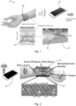
- the present disclosure may be embodied as a system 10 (sometimes referred to herein as "WearNet” or the “WearNet system”) having an implantable sensor 20 and a wearable interface device 30 .
- the implantable sensor 20 is configured to be implanted subcutaneously in an individual.
- the implantable sensor 20 may be a nanoplasmonic chip.
- the sensor 20 comprises an array of surface plasmon resonance (SPR) biosensors 21 .
- the sensor 20 may comprise a thin film 25 made of a material that supports propagation of plasmons- i.e ., materials having complex value conductivity (hereinafter called an "SPR film").
- the SPR film 25 may be a metallic film such as, for example, gold, silver, or other metals or combinations (alloys) of metals.
- a plurality of gratings 24 are disposed proximate to the SPR film 25 .
- the plurality of gratings 24 may be made from a dielectric material, such as, for example, silicon.
- the sensor 20 may be built on a substrate 22 , such as, for example, a flexible substrate ( e.g ., PDMS, etc.)
- the sensor 20 may include nano-patterns for grating-coupled surface plasmon resonance (SPR)-based detection of the target biomarker.
- SPR surface plasmon resonance
- a plurality of gratings 24 may be arranged on a bottom surface of the substrate 22.
- a target biomarker may be defined by surface-treating the sensor 20 to immobilize selected chemicals.
- the sensor 20 may further include a plurality of optical couplers 23 located on a top surface of the substrate 22 . Each optical coupler 23 is configured such that light received at the optical coupler 23 is focused ( i.e., directed) to a corresponding biosensor 21 of the array of SPR biosensors.
- the sensor 20 is further described below.
- the system 10 further includes an interface device 30 configured to be worn by the individual at a location proximate to the implantable sensor 20 .
- the interface device 30 may be, for example, a nanophotonic smart band.
- the interface device 30 includes a plurality of emitters 32 for emitting excitation energy (for example, light) to the sensor 20 .
- Each emitter 32 of the plurality of emitters is configured to emit light to a corresponding biosensor 21 of the implantable sensor 20 .
- each emitter 32 may emit light which is received by a corresponding optical coupler 23 and directed to a corresponding biosensor 21 .
- the emitted light may be of any appropriate wavelength.
- the emitted light may be in the visible spectrum, near infrared, far infrared, etc.
- Each emitter 32 may emit light at the same wavelength as the other emitters or may emit light at a different wavelength from the other emitters.
- the emitters 32 may be lasers, such as, for example, orbital angular momentum microlasers, single-mode microring lasers, or three-dimensional subwavelength metallo-dielectric semiconductor lasers.
- the emitters may be the same type of emitters or may be different types of emitters.
- the interface device 30 also includes a plurality of detectors 34 for receiving energy (for example, reflected light) from the sensor 20 .
- the plurality of detectors 34 may be, for example, a CCD array. In the example of a CCD array, each pixel of the array, or subsets of pixels of the array, may be considered as a separate detector 34 .
- Each detector 34 is configured to receive light reflected by a corresponding biosensor 21 of the implantable sensor 20 .
- active components of the system 10 can be located outside the user's body, and the wearable interface device 30 serves as a nano-to-macro interface between bio-events and the individual.
- the system 10 may also include a remote processor 40 for processing data received from the sensor 20 (via the wearable interface device 30, as further described below).
- the remote processor 40 may be programmed with signal processing algorithms to post-equalize the measured signals by, for example, taking into account the intra-body optical channel, filtering stochastic ambient background noise (created by other biomarkers present in the medium), combining the measured signal at each of photodetector, and, ultimately, providing reliable data to the user or a healthcare practitioner.
- the collected data may be anonymized and contributed to a cloud-based database, where it can be accessible to researchers both to develop new understanding and as training sets for machine-learning algorithms that can improve automatic diagnosis algorithms.
- the presently-disclosed wearable device may incorporate a network of nano-devices that are able to simultaneously excite and cooperatively reconstruct the response of nanoplasmonic biochips. While the presently-disclosed platform could accommodate different nano-biosensing technologies, the present disclosure will be described with reference to an illustrative, non-limiting embodiment used to monitor the progression of lung cancer. It is noted that the disclosure is not intended to be limited to only this illustrative embodiment, and other applications will be apparent in light of the disclosure. Poor survival of cancer patients is mainly caused by tumor heterogeneity, late diagnosis, lack of effective treatment and cancer recurrence, reflecting the urgent need of next-generation medicine that combines sensitive diagnosis, personalized therapy and effective surveillance to overcome these challenges and improve the survival of cancer patients.
- the nanoplasmonic biosensing technology may comprise four main components, namely, (1) an implantable nanoplasmonic biochip having multiplexed sensor arrays, for example, to lung cancer detection from biomarkers in blood; (2) arrayed optical adiabatic couplers for enhancing the light-plasmon coupling efficiency attached to the biochip, the biochip and couplers configured to be embedded underneath the skin of a user; (3) compact optical nano-sources to excite the plasmonic nanoprobes; and (4) arrayed photodetectors able to measure the biosensing signals through reflection, both integrated in a wearable device. See, for example, Figure 3 .
- Nanoplasmonic biosensors employing nanoscale topographies are attractive miniaturized platforms for label-free, high throughput and sensitive monitoring of bio/chemical analytes.
- receptor molecules When receptor molecules are immobilized on nano-structured metal surfaces, the binding of target biomolecules changes the local refractive index (RI), affecting the optical properties of the surface plasmon (SP) modes and permitting optical detection.
- RI refractive index
- SP surface plasmon
- Recent advances in fabrication, material synthesis, and characterization provide nanoplasmonic sensors with a competitive edge over conventional surface plasmon resonance (SPR) sensors.
- SPR surface plasmon resonance
- Most previously-reported plasmonic sensing devices are based on wavelength interrogation.
- high spatial density multiplexed measurements are difficult to achieve in that broadband. Wavelength analysis via spectrometer is required, which inevitably adds to the size and cost of the entire system.
- a more compact sensing strategy is required to enable in-vivo sensing of biomarkers using an embedded sensing node.
- the present device may include a grating-coupled SPR arrangement which is amenable to standard fabrication processes.
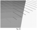
- a dielectric coupling grating is on an opposite side of a flat metal film, enabling convenient integration with compact optical couplers (e.g ., optical fiber tips) for implantable biomedical sensing.
- FIG. 5A An example of the structure is illustrated in Figure 5A .
- a 50-nm-thick Au film is deposited on a glass substrate followed by a deposition of 350-nm-thick single-crystal Silicon (Si) film.
- Si single-crystal Silicon
- standard top-down nanofabrication methods e.g ., optical interference lithography and nanoimprint lithography
- titanium or chromium thin-films can be inserted at the Au and Si interface.
- Transparent biocompatible adhesive materials e.g ., LOCTITE Light Cure Medical Device Adhesives (Henkel Inc.), n ⁇ 1.545
- LOCTITE Light Cure Medical Device Adhesives Henkel Inc.
- n ⁇ 1.545 can be used to remove (e.g ., peel) the layers from the glass substrate, following a recently reported peeling-off procedure.
- This peeling-off procedure has been used in fabricating large area 1D and 2D metallic nanogratings successfully.
- a first side of the metal film is exposed to the environment, which can be used for optical sensing.
- a second side of the metal film faces the blood to sense circulating biomarkers.
- the sensing and detection are located on different sides of the metal film, which will significantly reduce the inference from the blood on the signal collection.
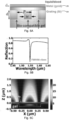
- the refractive index of the bulk material on the top surface was tuned from 1.333 ( i.e., water) to 1.338 and the reflection spectrum was modeled, as shown in Figure 5D .
- the estimated FOM is 300, which is much better than reported FOMs obtained by other nanoplasmonic sensor architectures (e.g., typically ⁇ 10 based on nanoparticles).
- the grating structure may be fabricated using advanced photopatterning processes (e.g., optical interference lithography) over large areas.
- advanced photopatterning processes e.g., optical interference lithography
- interference photopatterning technologies were successfully used to fabricate large area polymer holographic gratings and 1D/2D metallic gratings.
- 1D and 2D nanograting patterns were fabricated.
- the optical patterning area could be, for example, 20 ⁇ 30 mm in diameter ( Figure 5E ).
- the exemplary photopatterning process has been scaled up to ⁇ 1 meter in diameter for yield production.
- an embodiment of the implantable sensor has a target side length of ⁇ 10-100 ⁇ m
- building large samples and then cutting the sample into small sensors may provide reduced costs.
- 2D grating structures are fabricated to address the polarization sensitivity of 1D grating structures. In this case, any polarization direction of the light can be coupled to SP modes efficiently.
- the gratings on flat metal films may be peeled off using, for example, a bio-compatible gel attached to a glass substrate.
- optical lithography may be employed to identify optical coupler, as illustrated in Figure 3 , which will be used to couple and guide light from the emitter (e.g ., ring laser) described in Section I.c as the normal incidence.
- the emitter e.g ., ring laser
- High-efficiency coupling allows an increase in the depth of the implant within the body. While the target depth for the exemplary embodiment was ⁇ 1-2 mm, deeper sites could be reached by increasing the coupler length.
- Solutions e.g ., water, PBS, etc.
- standard biomolecules e.g ., BSA, anti-BSA, etc.
- a nanoplasmonic biochip may be utilized to monitor circulating CYFRA 21-1 for lung cancer diagnosis and surveillance.
- Lung cancer was selected as the illustrative disease model because it is the leading cause of cancer deaths worldwide, currently accounting for over 1.37 million deaths a year. The overall five-year survival rate of lung cancer remains 15%, which has not significantly changed since 1970s.
- the nanoplasmonic biochip may be used to measure the levels of circulating biomarkers in patient blood to, for example: (1) provide information of tumor products in the periphery to complement more invasive and expensive testing; (2) monitor the treatment response to realize personalized therapy; and (3) closely follow the disease progression and predict cancer recurrence.
- CYFRA 21-1 is cytokeratin 19 fragment whose levels in the blood are closely related with disease stage, prognosis, and treatment response. High CYFRA 21-1 levels in the blood indicate advanced tumor stage and poor prognosis. Significant decrease of the CYFRA 21-1 level is observed after effective therapy, while insufficient decline of CYFRA 21-1 post treatment indicates poor outcome.
- EIA Enzyme Immunoassay
- FDA U.S. Food and Drug Administration
- CYFRA 21-1 was selected as the model biomarker in the illustrative embodiment used to demonstrate the feasibility of the WearNet system and to compare its sensing performance with the CYFRA 21-1 EIA kit (FUJIREBIO Diagnostics, Inc.)
- the surface of the nanoplasmonic biochip may be coated with a mixture of PEG200 and biotin-PEG1000. Then, biotin-avidin interaction will be used to attach biotinylated monoclonal cytokeratin 19-specific antibody to the surface.
- biotin-avidin interaction will be used to attach biotinylated monoclonal cytokeratin 19-specific antibody to the surface.
- the following parameters were considered: (1) the ratio of PEG200 and Biotin-PEG-1000 (1:1, 1:2, and 1:3); (2) Neutravidin concentration (0.05 and 0.1 mg/mL); (3) antibody concentration (0.05 and 0.1 mg/mL), and (3) the on-chip incubation time of PEG, Neutravidin, and antibody (0.5, 1, and 2 hr).
- the sensing performance of the exemplary biochip may be evaluated using CYFRA 21-1 antigen spiked in blood samples from healthy controls.
- CYFRA 21-1 EIA kit (FUJIREBIO Diagnositics, Inc.) can also be used to measure the concentrations of CYFRA 21-1 antigen in the same samples. Results can be used to quantify the detection sensitivity and specificity of the biochip and compare with that of CYFRA 21-1 EIA kit.
- Embodiments of the present device include a plurality of emitters.
- the emitters may be, for example, an array of optical laser sources to illuminate and excite the nanoplasmonic biochip.
- the laser sources may be micro/nano optical lasers.
- an embodiment may include laser resonators based on a III-V semiconductor platform for room temperature lasing action, such as, for example: orbital angular momentum microlasers that directly emit twisted vortex light at the microscale, single-mode microring lasers using parity-time (PT) symmetry, or 3D subwavelength metallo-dielectric semiconductor lasers incorporating a dielectric shield layer.
- PT parity-time
- CMOS complementary metal-oxide semiconductor
- suitable micro/nano lasers on a III-V semiconductor platform i.e., InP and GaAs composites
- the fabrication of ultrastable micro laser sources may make use of overlay lithography with alignment error controlled below 10 nm.
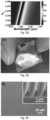
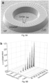
- Figure 6A shows a fabricated complex-index-modulated microring laser cavity using the overlay lithography.
- the properties of the laser sources may be characterized, for example, as shown in Figure 6B , where ultrastable single-mode operation was successfully demonstrated with pump power consumed only on the order of ⁇ W.
- the preliminary results in Figure 6B show the laser action in the telecom band around the wavelength of 1500 nm, matching the operational wavelength range of an exemplary nanoplasmonic biochip.
- Laser characteristics such as, for example, polarization, emission directionality, wavefront shape, and/or wavelength optimization may be tuned so as to further enhance a laser's use in nanoplasmonic biosensing.
- Thermo-optical modulations may also be used in the integration of the micro/nano laser sources to enable precise control for achieve a desired laser wavelength.
- micro/nano laser sources are their intrinsic ability to be highly distributed. With the emission directionality and power of each individual micro/nano laser precisely controlled, the highly-distributed feature dramatically simplifies the integration of a number of laser sources around the wearable device (e.g ., a watch-like form factor, see Figures 1 and 2 ) in the fashion of forming an optical nano-network to specifically enhance the illumination and excitation of the nanoplasmonic biochips. As such, nanophotonic arrays can be integrated and controlled to aid the detection of the received signals in favor of optimized computer algorithms.
- an array of photo-detectors such as a charge-coupled device (CCD) camera chip, can be integrated on a different physical layer, for example, above the emitters (optical sources), to capture the reflected light.
- each photodetector e.g ., each individual pixel on a CCD chip, or subsets of pixels of a CCD chip, can be aligned with each optical source and its corresponding nanoplasmonic bio-pixel to efficiently capture the sensing signal through reflection.
- the cavities may be ring-shaped, favoring the transmission of reflected light through central hollow area of each emitter to its corresponding detector.
- a III-V semiconductor InP chip looks opaque with visible light, it is transparent for other wavelengths, for example, the "telecom" window of around 1500 nm.
- the biosensing signals to be measured are expectedly weak, at least when compared to traditional desktop or portable biosensors equipped with large-size lasers, due to the much lower excitation power.
- the micro/nano-lasers individually switch on and off to collect spatially distributed data (see further description below Section II).
- the information is transmitted to the user's smartphone.
- Bluetooth may be utilized for data transfer. It should be noted that other wireless technologies exist and others are under development for BANs. Any of these technologies may be used.
- the much larger computational power of the smartphone can be leveraged to implement real-time algorithms to aggregate the response signals, eliminate the impacts from multi-path scattering in the intra-body channel, extract the relevant information to generate a diagnose, and securely share the data and diagnose with an online cloud-based database.
- Data reconstruction and analysis techniques can be used to enhance the useful information to be extracted from the large amount of measurements captured by the plasmonic nano-biosensing network.
- the plurality of detectors across the wearable device send their measurements via a transceiver (for example, a Bluetooth transceiver) from the wearable device to the remote processor (for example, a smartphone), where the data reconstruction and analysis are conducted.
- a transceiver for example, a Bluetooth transceiver
- the remote processor for example, a smartphone
- a large number of detectors may be deployed to (i) enhance the measured signal strength and (ii) explore the spatial diversity to improve signal quality.
- An objective of data reconstruction is to accurately rebuild the time-domain response of the implanted nanoplasmonic biochips using a large number of independent measurements, obtained from the network of detectors on the wearable device.
- a large amount of data points may be beneficial for each measurement. These may be obtained from many distributed detectors that are deployed across the wearable device and experience different channel attenuation, signal distortion, and delay. There are three key influential factors that may be considered for data reconstruction: (1) the intra-body channel that affects the propagation of optical signals from the light sources to the biochip and back to the detectors; (2) the nontrivial distortion, noise, and delay introduced when capturing and digitizing the received signals at each detector; and (3) the offsets between the measurements reconstructed at each detector in terms of arrival time, rising time, and amplitude.
- a novel intra-body channel model has been developed to characterize the signal propagation and distortion between the nanoplasmonic biochip and the detectors through different body components, including blood and other body fluids, vessel walls, bones, muscles, fat and skin.
- the model is different from traditional channel models where the human body is described as a layered material with different permeability and permittivity
- the intra-body channel is characterized from the perspective of the detectors: the body is a collection of different types of elements, such as cells, organelles, proteins, and molecules, with different geometry and arrangement as well as different EM properties.
- existing models are mostly valid only when a large area (in terms of wavelength) is illuminated, a channel model is developed that works when nano-sources with very small apertures are utilized.
- the present models can accurately predict the channel path loss by taking into account the absorption from different types of molecules and the scattering by different types of cells.
- the signal path loss is shown as a function of distance under the influence of the cells in the intra-body channel.
- the significant scattering effects are illustrated when optical waves propagate through a group of cells.
- the channel impulse response for different shapes of the cells is plotted in time domain, which shows different type, position, and direction of the cells in the intra-body channel can dramatically change the delay and shape of the response signal from the nanoplasmonic biochip.
- the intra-body channel models can be used to estimate the attenuation, delay, and distortion caused by the signal propagation inside human body.
- a link-budget analysis can be performed to estimate the required emission power of nano/micro-lasers (Section I.c, with the human factors constraints in Section III.b), and the number, size and depth of the implants (Sections I.a and I.b with the human factor constraints in Section III.a).
- the influence of the intra-body channel can be mitigated by post-equalization.
- the weakened optical signals received at each photodetector can be digitized for signal processing purposes.
- additional distortion and noise is introduced.
- any non-linearity of the photodetectors introduces additional distortion.
- the analog-to-digital converter (ADC) converts the captured continuous analog signal to a digital signal sequence.
- ADCs can bring quantization error and integral nonlinearity (INL), which can further distort the reconstructed signal at each detector. These factors can be analyzed, and the reconstructed signals can be corrected accordingly.
- Data reconstruction at a remote processor for example, a mobile device such as a smartphone
- a Bluetooth wireless link can transmit a digitized signal captured by each detector to a smartphone
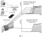
- An example of data reconstruction in a WearNet system is illustrated in Figure 7 .
- the relevant diagnosis information of the ideal (ground truth) response signal from the nanoplasmonic biochip lies in the transient part of the time-domain signal. Since the signal transient may be very short and very sensitive to noise, delay, and distortion, an objective of the data reconstruction algorithm in WearNet may be to control and mitigate those impacts.
- the arrayed nanolasers may be individually controlled and space sweeping algorithms can be used to first localize the nanosensor and then focus on the actual device and collect the data (Section I.c). Since different detectors may be placed at different locations in the wearable device, the measured signals experience different channel influences during the propagation inside human body. In addition, in some embodiments, a photodetector and an ADC at each detector can impose unique distortions to each reported digitized signal. Moreover, the time spot of each measurement can be slightly different from each other since there is no strict synchronization among the detectors.
- the remote processor may be programmed to combine the large number of measurements with significant offsets from the detectors.
- the offsets caused by the channel and sensor hardware may be reduced.
- the spatial and temporal correlations among the detectors may be used to further reduce the offsets, by running calibration algorithms that exploit the capability of switching on/off individual micro/nano-lasers (the locations of the detectors are supposed to be known through the communication between the wearable devices and the smartphone).
- the digital data reconstructed at the remote processor provides the raw materials for smart health diagnosis. Compared with the traditional wearable devices that take simple heart rate or blood glucose (can be considered as a 1-digit data), the presently-disclosed detectors network system can provide tremendously detailed information for automatic or remote health diagnosis.
- the reconstructed response signal from the nanoplasmonic biochip may be analyzed from an information-theoretic perspective to extract useful information for diagnosis.
- Information capacity of reconstructed biochip response signals The amount of information which can be delivered by the presently-disclosed wearable nano-biosensing networks can be characterized.
- the amount of information carried by the reconstructed response signal from the nanoplasmonic biochip can be characterized (the "information" is the mutual information, i.e., how much uncertainty (entropy) of the diagnosis of a certain disease, e.g ., lung cancer, can be reduced by analyzing the reconstructed response signal).
- the impact of the intra-body channel, detectors hardware, and the offset among distributed measurements can be quantitatively captured so that improved strategies can be determined according to the resulted information capacity.
- biochip response signals can be extremely large, not every single bit of the capacity may be essential for the disease diagnosis. Where present, such non-essential information in the reconstructed response signal from the nanoplasmonic biochip may create unnecessary requirements for hardware precision and computation complexity. Moreover, the non-essential information also increases the diagnosis complexity.
- a data extraction process may be used to derive the essential diagnosis information from the biochip temporal signals. Such a data reduction process may use dimensionality reduction techniques, such as PCA and Fisher LDA, to find the most discriminant subspaces of signals that can highlight the relevant features of the monitored biological process.
- a dimensionality reduction solution may rely on the database of diagnosis results that are based on the response signal from the biochip.
- the system may also provide for data sharing and/or database.
- the system may include data sharing for WearNet system so that the health monitoring information from users and diagnosis results can be used for system learning. In this way, automatic diagnosis may be used.
- the WearNet system may provide, for example, data regarding the measured time-response of the biochip. Such data may need to be interpreted by a medical doctor to generate a diagnostic. Ultimately, the measured responses and the doctor's diagnoses may be used to generate and train new algorithms for accurate one-to-one matching and diagnostics.
- the learning mechanism may be formulated as a classification problem: the extracted information from the WearNet is used as the input feature and the diagnosed disease is viewed as the output classification results.
- the system may include a database that is securely controlled by a WearNet administrator. This will enable WearNet users to share their monitor and diagnosis results thereby improving the automatic diagnosis capability.
- the success of the presently-disclosed smart health system may be improved by its ability to capture the human factors that affect its design. These include the biocompatibility of the nanoplasmonic biochips and the wearable devices ability to collect, process, and distribute sensitive data related to the users' health.
- the performance of an implanted biochip may be expected to degrade over time due to factors such as surface biofouling caused by nonspecific binding of biomaterials (biomolecules, cells), or the reduction of binding receptors, etc.
- the former effect can inhibit the access and binding of a target analyte to sensor receptors, the latter effect leads to a reduction of bound analyte.
- These effects and others can severely limit the sensor signals, and may need to be addressed to broadly advance applications of imbedded sensors.
- the presently-disclosed system may utilize minimally invasive methods for addressing such issues, such as, for example, transcutaneous application of sensor regeneration agents, enthalpic and entropic interactions, chemical and electrochemical regeneration, etc.
- the system may utilize noninvasive methods involving acoustic, thermal, optical, and electromagnetic transduction mechanisms (focused ultrasound (sonication), photothermal heating, optical tweezing, etc.) that can potentially dislodge fouling agents. include to delodge fouling agents.
- the in-vivo sensing and networking technologies described herein may result in irradiating tissue with laser light to enable the use of the plasmonic nanoprobes.
- tissue heating involves many thermodynamic processes that act in parallel, over different temperature ranges and with different reaction rates. These effects include skin burns, collagen denaturation (breakdown) and cellular necrosis (destruction), among others.
- the local laser beam fluence rate laser ⁇ (W/m 2 ) may be controlled to avoid deleterious tissue heating and damage.
- T is the local tissue temperature (K)
- ⁇ is the tissue density (kg/m 3 )
- C T is the heat capacity of tissue (J kg -1 K -1 )
- k is the diffusion due to blood flow (W/mK)
- C b is the heat capacity of blood
- ⁇ b is the perfusion due to blood flow (kg b l kg tissues )
- ⁇ b is the density of blood
- T B is the arterial blood temperature
- ⁇ is the relaxation time.
- the nanoplasmonic biochip contributes to the local tissue heating through the per absorption cross-section ⁇ BC (m 2 ).
- ⁇ BC ⁇ laser is the laser-induced heat generated per unit volume by the biochip (W/m 3 ), which will be maximum at their localized LSPR.
- Equation (1) may be solved to predict the temperature rise in target tissues from first principles to enhance embodiments of the networking system and biochips. Viable levels of laser fluence ⁇ laser and biochip properties ( n p and ⁇ BC ) may be used to limit heating.
- a wireless Bluetooth link between the wearable interface device and remote processor (e.g ., smartphone), and the wireless/wired link between the remote processor and a data server or a remote medical doctor.
- the security of the link between the remote processor and the remote server or doctor can be provided by the security protocols used in the cellular network, including (1) authenticating users by the international mobile subscriber identity (IMSI, kept in the SIM card) and a shared secret key; and (2) encrypting user data through various encryption, confidentiality, and integrity algorithm sets.
- the security of the wireless Bluetooth link may be achieved using, for example, pre-shared key authentication and encryption algorithms.
- a friendly jamming device may be used where either the wearable device or the smartphone radiate a strong noise signal during the wireless data transmission.
- the eavesdropper cannot detect the transmitted data, which disabled their attacks.
- the smartphone can extract the data from the noise since the smartphone knows all the parameters of the self-generated noise.
- Other security protocols may be used in addition to, or instead of, those described herein.
- the wearable interface device comprise of two main elements: a nanosensing front-end (laser sources and CCD detector) and an integrated controller circuit.
- a nanosensing front-end laser sources and CCD detector
- an integrated controller circuit integrated circuit.
- PDMS polydimethylsiloxsane
- the nanophotonic devices including lasers and detectors discussed in previous sections, may be implemented on a polymer-based flexible platform, which can be further integrated on wearable devices.
- Some embodiments of the integrated controller circuit include three major functions: (1) to convert the analog measurements from the CCD array to digital signals; (2) to forward the digitized measurement data to the remote processor through Bluetooth link; and (3) to control the intelligent logic of the wearable device, including, for example, sleep/wake up, Bluetooth pairing, and jamming for security, among others.
- Figure 9 illustrates an exemplary design that includes a microcontroller to implement the logic and coordination of the other components, an ADC to convert the analog signal from the detectors (e.g., CCD, etc.) and send the digital data to the microcontroller, a Bluetooth radio chip and 2.4 GHz patch antenna to transmit the digital measurements to the smartphone, and a power unit to supply the power to all the components
- testbeds can be used in order to characterize the performance of embodiments of the presently-disclosed system.
- TEPs Tissue-Equivalent Phantoms
- TEPs are specially prepared synthetic materials designed to have optical (scattering, absorption) and thermal (heat capacity, diffusivity) properties that match human tissue over a desired frequency range.
- TEPs can be used to characterize the scattering, absorption, attenuation of EM waves within select tissues due to both the incident laser light and radiation from embodiments of the nanoplasmonic biochips.
- Photothermal tissue heating can also be characterized using TEPs, and resulting models can be validated.
- Microcirculation Tissue-Equivalent Phantoms comprise vessels ( ⁇ 100 ⁇ m in diameter), arterioles, capillaries and venules.
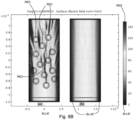
- Microcirculation tissue-equivalent phantoms can be fabricated (see Figure 10 ). Specifically, microfluidic flow networks can be fabricated within TEP materials to mimic in-vivo blood-flow conditions. Such phantoms can then be used to characterize the irrigation of the implanted biochips within the circulatory system.
- a testbed for the disclosed technology can be realized by implanting a nanoplasmonic biochip described herein into a microcirculation tissue-equivalent phantom networks platform ( Figure 10 ) and utilizing a prototype wearable device, having a nano-sensing front-end (Section I.c) and microcontroller ( Figure 9 ), to excite and measure the biochip-scattered signal collectively, and send it via Bluetooth to a smartphone.
- a mobile app that implements the data reconstruction and analysis algorithms (Section II) can be used with the collected data.
- Performance parameters such as, for example, measurement SNR as a function of the number of active nano-sources and detectors on the wearable device, SNR as a function of the on-off duty cycle of the optical nano-sources, and body temperature increase as a function of the number of active nano-sources and their duty cycle, can be analyzed.
Landscapes
- Health & Medical Sciences (AREA)
- Life Sciences & Earth Sciences (AREA)
- Engineering & Computer Science (AREA)
- Physics & Mathematics (AREA)
- Pathology (AREA)
- General Health & Medical Sciences (AREA)
- Public Health (AREA)
- Biomedical Technology (AREA)
- Heart & Thoracic Surgery (AREA)
- Medical Informatics (AREA)
- Molecular Biology (AREA)
- Surgery (AREA)
- Animal Behavior & Ethology (AREA)
- Biophysics (AREA)
- Veterinary Medicine (AREA)
- Computer Networks & Wireless Communication (AREA)
- Optics & Photonics (AREA)
- Chemical & Material Sciences (AREA)
- Physiology (AREA)
- Chemical Kinetics & Catalysis (AREA)
- General Chemical & Material Sciences (AREA)
- Spectroscopy & Molecular Physics (AREA)
- Nanotechnology (AREA)
- Analytical Chemistry (AREA)
- Biochemistry (AREA)
- General Physics & Mathematics (AREA)
- Immunology (AREA)
- Investigating Or Analysing Materials By Optical Means (AREA)
Claims (15)
- Système (10) destiné à détecter et à mesure des biomarqueurs, comprenant :un capteur implantable (20) configuré pour être implanté dans une personne, comprenant :un réseau de biocapteurs de résonance des plasmons de surface, SPR, (21) ; etune pluralité de coupleurs optiques (23) située au niveau d'une surface supérieure du capteur implantable, chaque coupleur optique configuré de manière fonctionnelle de sorte que la lumière reçue au niveau du coupleur optique est focalisée vers un biocapteur correspondant du réseau de biocapteurs SPR ;un dispositif d'interface (30) configuré pour être porté par la personne à proximité du capteur implantable, comprenant :une pluralité d'émetteurs (32), chaque émetteur configuré pour émettre de la lumière vers un coupleur optique correspondant du capteur implantable ; etune pluralité de détecteurs (34), chaque détecteur configuré pour recevoir de la lumière réfléchie par un biocapteur correspondant du capteur implantable.
- Système selon la revendication 1, dans lequel le réseau de biocapteurs SPR (21) comprend un substrat (22) avec une surface supérieure et une surface inférieure, dans lequel la surface supérieure est configurée pour être positionnée vers l'extérieur du corps de l'utilisateur quand il est implanté ;une pluralité de grilles (24) disposée sur la surface inférieure du substrat ; etun film de SPR (25) sur la pluralité de grilles.
- Système selon la revendication 2, dans lequel le film de SPR (25) est un film métallique.
- Système selon la revendication 2 ou la revendication 3, comprenant en outre un gel biocompatible entre le substrat (22) et la pluralité de grilles (24).
- Système selon la revendication 1, dans lequel chaque émetteur dans la pluralité d'émetteurs (32) est un laser.
- Système selon la revendication 5, dans lequel chaque laser dans la pluralité d'émetteurs (32) est un microlaser à moment angulaire orbital.
- Système selon la revendication 5, dans lequel chaque laser dans la pluralité d'émetteurs (32) est un laser à micro-anneau à mode unique.
- Système selon la revendication 5, dans lequel chaque laser dans la pluralité d'émetteurs (32) est un laser semi-conducteur métallo-diélectrique à sous-longueur d'onde tridimensionnelle.
- Système selon la revendication 8, dans lequel chaque laser semi-conducteur métallo-diélectrique à sous-longueur d'onde tridimensionnelle contient une couche de blindage diélectrique.
- Système selon la revendication 1, comprenant en outre un processeur distant (40), dans lequel le processeur distant est configuré pour réaliser la post-égalisation d'un signal mesuré sorti par un détecteur de la pluralité de détecteurs (31), extraire par filtration le bruit de fond ambiant stochastique à partir du signal mesuré, et combiner les signaux mesurés sortis par chaque détecteur.
- Système selon la revendication 1, dans lequel le dispositif d'interface (30) comprenant en outre un émetteur-récepteur,
dans lequel l'émetteur-récepteur est de préférence un émetteur-récepteur Bluetooth. - Système selon la revendication 1, comprend en outre un processeur distant (40) en communication sans fil avec le dispositif d'interface (30).
- Système selon la revendication 12, dans lequel le processeur distant (40) est un téléphone intelligent.
- Système selon la revendication 12, dans lequel le processeur distant (40) est configuré pour émettre des données reçues du capteur (20) via le dispositif d'interface (30) à un médecin pour une analyse.
- Système selon la revendication 12, comprenant en outre un serveur de données, dans lequel le processeur distant (40) est configuré pour traiter des données reçues du capteur (20) via le dispositif d'interface (30) en un ensemble de données anonymes et émettre l'ensemble de données anonymes au serveur de données, dans lequel le serveur de données est configuré pour stocker l'ensemble de données anonymes.
Applications Claiming Priority (2)
| Application Number | Priority Date | Filing Date | Title |
|---|---|---|---|
| US201762607897P | 2017-12-19 | 2017-12-19 | |
| PCT/US2018/066545 WO2019126352A1 (fr) | 2017-12-19 | 2018-12-19 | Système intelligent de soins de santé |
Publications (3)
| Publication Number | Publication Date |
|---|---|
| EP3729059A1 EP3729059A1 (fr) | 2020-10-28 |
| EP3729059A4 EP3729059A4 (fr) | 2021-09-08 |
| EP3729059B1 true EP3729059B1 (fr) | 2023-05-03 |
Family
ID=66992835
Family Applications (1)
| Application Number | Title | Priority Date | Filing Date |
|---|---|---|---|
| EP18892718.0A Active EP3729059B1 (fr) | 2017-12-19 | 2018-12-19 | Système de détection de biomarqueurs avec capteur spr implantable |
Country Status (4)
| Country | Link |
|---|---|
| US (1) | US11406266B2 (fr) |
| EP (1) | EP3729059B1 (fr) |
| CA (1) | CA3086513A1 (fr) |
| WO (1) | WO2019126352A1 (fr) |
Families Citing this family (7)
| Publication number | Priority date | Publication date | Assignee | Title |
|---|---|---|---|---|
| US20220387995A1 (en) * | 2019-10-24 | 2022-12-08 | The Regents Of The University Of Michigan | An Integrated Smart Point-Of-Care Biosensor for Whole-Blood Liquid Biopsies |
| WO2021185589A1 (fr) * | 2020-03-17 | 2021-09-23 | Sony Group Corporation | Vérification de la préservation de la confidentialité de données d'utilisateur |
| US20240350045A1 (en) * | 2021-08-27 | 2024-10-24 | Northeastern University | Implantable Biosensor and Communication Node With Plasmonic Nano-Antenna |
| GB2623298B (en) * | 2022-10-05 | 2025-01-15 | Polar Electro Oy | Replaceable patch for wearable training computer and wearable training computer |
| WO2025015421A1 (fr) * | 2023-07-17 | 2025-01-23 | Fonex Data Systems Inc. | Capteur basé sur une cavité laser et procédé de détection |
| CN118017238B (zh) * | 2024-04-09 | 2024-06-04 | 西南科技大学 | 基于人体姿态的模态可重构涡旋阵列天线 |
| WO2026071566A1 (fr) * | 2024-09-26 | 2026-04-02 | 삼성전자 주식회사 | Dispositif électronique portable et procédé d'acquisition d'informations biométriques l'utilisant |
Family Cites Families (11)
| Publication number | Priority date | Publication date | Assignee | Title |
|---|---|---|---|---|
| WO2003005890A2 (fr) * | 2001-07-09 | 2003-01-23 | Arizona Board Of Regents A Body Corporate Acting On Behalf Of Arizona State University | Biocapteur d'affinite destine a la surveillance de procedes biologiques |
| DE602004016687D1 (de) * | 2003-12-22 | 2008-10-30 | Paul Hadvary | Dermal befestigte sensorvorrichtung |
| US8355136B2 (en) * | 2005-12-16 | 2013-01-15 | Indiana University Research And Technology Corporation | Sub-micron surface plasmon resonance sensor systems |
| CA2668421A1 (fr) * | 2008-06-27 | 2009-12-27 | Tyco Healthcare Group Lp | Systeme et methode de detection optique continue de substance a analyser dans la circulation sanguine |
| WO2014052327A1 (fr) * | 2012-09-25 | 2014-04-03 | Alfred E. Mann Foundation For Scientific Research | Biocapteur de résonance de plasmon de microcanal |
| US10219729B2 (en) * | 2013-06-06 | 2019-03-05 | Profusa, Inc. | Apparatus and methods for detecting optical signals from implanted sensors |
| WO2015123457A1 (fr) * | 2014-02-12 | 2015-08-20 | California Institute Of Technology | Nanostructures plasmoniques pour multiplexage de capteurs implantables |
| EP3709001B1 (fr) * | 2015-11-10 | 2024-03-06 | LacriSciences LLC | Systèmes et procédés de détermination de l'osmolarité d'échantillons |
| CN208141404U (zh) * | 2017-10-19 | 2018-11-23 | 金佶科技股份有限公司 | 指纹辨识装置 |
| WO2019168913A1 (fr) * | 2018-02-28 | 2019-09-06 | Pop Test Oncology Llc | Dispositifs médicaux et leurs utilisations |
| EP4049032A1 (fr) * | 2019-10-25 | 2022-08-31 | Cercacor Laboratories, Inc. | Composés indicateurs, dispositifs comprenant des composés indicateurs, et leurs procédés de fabrication et d'utilisation |
-
2018
- 2018-12-19 CA CA3086513A patent/CA3086513A1/fr not_active Abandoned
- 2018-12-19 US US16/956,465 patent/US11406266B2/en active Active
- 2018-12-19 WO PCT/US2018/066545 patent/WO2019126352A1/fr not_active Ceased
- 2018-12-19 EP EP18892718.0A patent/EP3729059B1/fr active Active
Also Published As
| Publication number | Publication date |
|---|---|
| CA3086513A1 (fr) | 2019-06-27 |
| EP3729059A1 (fr) | 2020-10-28 |
| WO2019126352A1 (fr) | 2019-06-27 |
| US20210121065A1 (en) | 2021-04-29 |
| EP3729059A4 (fr) | 2021-09-08 |
| US11406266B2 (en) | 2022-08-09 |
Similar Documents
| Publication | Publication Date | Title |
|---|---|---|
| EP3729059B1 (fr) | Système de détection de biomarqueurs avec capteur spr implantable | |
| Peng et al. | Blood glucose sensors and recent advances: A review | |
| EP2207474B1 (fr) | Capteur optique pour déterminer la concentration d'une substance à analyser | |
| CN102697510B (zh) | 使用组织荧光确定某一糖化终产物或疾病状态 | |
| CN100522059C (zh) | 血糖值的非侵入测量装置 | |
| US20140171759A1 (en) | Noninvasive determination of intravascular and exctravascular hydration using near infrared spectroscopy | |
| TW200404156A (en) | Compact apparatus for noninvasive measurement of glucose through near-infrared spectroscopy | |
| US20140155760A1 (en) | Remote and local transfer of information in noninvasive hydration measurements | |
| KR20170012166A (ko) | 바이오메트릭 기반 정보 통신을 이용한 실시간 의학적 상태 모니터링을 위한 생의학 디바이스들 | |
| KR20170012165A (ko) | 바이오메트릭 기반 정보 통신 및 피드백용 생의학 디바이스 | |
| KR20170012163A (ko) | 바이오메트릭 기반 정보 통신용 생의학 디바이스들의 식별 양태 | |
| KR20170012162A (ko) | 바이오메트릭 기반 정보 통신용 생의학 디바이스 | |
| CN104266996A (zh) | 基于近红外光谱分析的多功能无创便携医疗检测装置及检测方法 | |
| US20220357279A1 (en) | Dual wavelength combined fingerprint and high wavenumber raman spectroscopy and applications of same | |
| KR20170012160A (ko) | 감지 및 바이오메트릭 기반 정보 통신을 위한 시스템들 및 생의학 디바이스들 | |
| KR20170012155A (ko) | 피로 감지와 관련된 바이오메트릭 기반 정보 통신용 생의학 디바이스 | |
| Bakhshi et al. | Securing internet of bio-nano things: ML-enabled parameter profiling of bio-cyber interfaces | |
| KR20180003227A (ko) | 유기 광 감지소자 기반의 비침습형 생체 센서 | |
| CN104027132A (zh) | 一种基于多谱光声成像的装置和方法 | |
| CN105596011B (zh) | 一种无创血糖检测装置 | |
| Kulkarni et al. | A feasibility study on noninvasive blood glucose measurement using photoacoustic method | |
| Irfani et al. | Continuous and non-invasive blood glucose measurements: a narrative review | |
| Liang et al. | A conformal piezoelectric microsystem for demographic-adaptive and calibration-free cuffless blood pressure monitoring | |
| JP2007020890A (ja) | 光学的生体情報計測システム及び光情報計測に用いられるカップリング層 | |
| Leong et al. | Smart Earring for Glucose Monitoring Using Fusion of mm-Wave Radar and Optical Spectroscopy |
Legal Events
| Date | Code | Title | Description |
|---|---|---|---|
| STAA | Information on the status of an ep patent application or granted ep patent |
Free format text: STATUS: THE INTERNATIONAL PUBLICATION HAS BEEN MADE |
|
| PUAI | Public reference made under article 153(3) epc to a published international application that has entered the european phase |
Free format text: ORIGINAL CODE: 0009012 |
|
| STAA | Information on the status of an ep patent application or granted ep patent |
Free format text: STATUS: REQUEST FOR EXAMINATION WAS MADE |
|
| 17P | Request for examination filed |
Effective date: 20200630 |
|
| AK | Designated contracting states |
Kind code of ref document: A1 Designated state(s): AL AT BE BG CH CY CZ DE DK EE ES FI FR GB GR HR HU IE IS IT LI LT LU LV MC MK MT NL NO PL PT RO RS SE SI SK SM TR |
|
| AX | Request for extension of the european patent |
Extension state: BA ME |
|
| DAV | Request for validation of the european patent (deleted) | ||
| DAX | Request for extension of the european patent (deleted) | ||
| REG | Reference to a national code |
Ref country code: DE Ref legal event code: R079 Ref document number: 602018049415 Country of ref document: DE Free format text: PREVIOUS MAIN CLASS: G01N0021550000 Ipc: G01N0021552000 |
|
| A4 | Supplementary search report drawn up and despatched |
Effective date: 20210809 |
|
| RIC1 | Information provided on ipc code assigned before grant |
Ipc: A61B 5/1455 20060101ALI20210803BHEP Ipc: A61B 5/145 20060101ALI20210803BHEP Ipc: A61B 5/00 20060101ALI20210803BHEP Ipc: G01N 21/552 20140101AFI20210803BHEP |
|
| GRAP | Despatch of communication of intention to grant a patent |
Free format text: ORIGINAL CODE: EPIDOSNIGR1 |
|
| STAA | Information on the status of an ep patent application or granted ep patent |
Free format text: STATUS: GRANT OF PATENT IS INTENDED |
|
| INTG | Intention to grant announced |
Effective date: 20221116 |
|
| GRAS | Grant fee paid |
Free format text: ORIGINAL CODE: EPIDOSNIGR3 |
|
| GRAA | (expected) grant |
Free format text: ORIGINAL CODE: 0009210 |
|
| STAA | Information on the status of an ep patent application or granted ep patent |
Free format text: STATUS: THE PATENT HAS BEEN GRANTED |
|
| AK | Designated contracting states |
Kind code of ref document: B1 Designated state(s): AL AT BE BG CH CY CZ DE DK EE ES FI FR GB GR HR HU IE IS IT LI LT LU LV MC MK MT NL NO PL PT RO RS SE SI SK SM TR |
|
| REG | Reference to a national code |
Ref country code: GB Ref legal event code: FG4D |
|
| REG | Reference to a national code |
Ref country code: DE Ref legal event code: R096 Ref document number: 602018049415 Country of ref document: DE |
|
| REG | Reference to a national code |
Ref country code: AT Ref legal event code: REF Ref document number: 1565012 Country of ref document: AT Kind code of ref document: T Effective date: 20230515 Ref country code: CH Ref legal event code: EP |
|
| REG | Reference to a national code |
Ref country code: IE Ref legal event code: FG4D |
|
| REG | Reference to a national code |
Ref country code: LT Ref legal event code: MG9D |
|
| REG | Reference to a national code |
Ref country code: NL Ref legal event code: MP Effective date: 20230503 |
|
| REG | Reference to a national code |
Ref country code: AT Ref legal event code: MK05 Ref document number: 1565012 Country of ref document: AT Kind code of ref document: T Effective date: 20230503 |
|
| PG25 | Lapsed in a contracting state [announced via postgrant information from national office to epo] |
Ref country code: SE Free format text: LAPSE BECAUSE OF FAILURE TO SUBMIT A TRANSLATION OF THE DESCRIPTION OR TO PAY THE FEE WITHIN THE PRESCRIBED TIME-LIMIT Effective date: 20230503 Ref country code: PT Free format text: LAPSE BECAUSE OF FAILURE TO SUBMIT A TRANSLATION OF THE DESCRIPTION OR TO PAY THE FEE WITHIN THE PRESCRIBED TIME-LIMIT Effective date: 20230904 Ref country code: NO Free format text: LAPSE BECAUSE OF FAILURE TO SUBMIT A TRANSLATION OF THE DESCRIPTION OR TO PAY THE FEE WITHIN THE PRESCRIBED TIME-LIMIT Effective date: 20230803 Ref country code: NL Free format text: LAPSE BECAUSE OF FAILURE TO SUBMIT A TRANSLATION OF THE DESCRIPTION OR TO PAY THE FEE WITHIN THE PRESCRIBED TIME-LIMIT Effective date: 20230503 Ref country code: ES Free format text: LAPSE BECAUSE OF FAILURE TO SUBMIT A TRANSLATION OF THE DESCRIPTION OR TO PAY THE FEE WITHIN THE PRESCRIBED TIME-LIMIT Effective date: 20230503 Ref country code: AT Free format text: LAPSE BECAUSE OF FAILURE TO SUBMIT A TRANSLATION OF THE DESCRIPTION OR TO PAY THE FEE WITHIN THE PRESCRIBED TIME-LIMIT Effective date: 20230503 |
|
| PG25 | Lapsed in a contracting state [announced via postgrant information from national office to epo] |
Ref country code: RS Free format text: LAPSE BECAUSE OF FAILURE TO SUBMIT A TRANSLATION OF THE DESCRIPTION OR TO PAY THE FEE WITHIN THE PRESCRIBED TIME-LIMIT Effective date: 20230503 Ref country code: PL Free format text: LAPSE BECAUSE OF FAILURE TO SUBMIT A TRANSLATION OF THE DESCRIPTION OR TO PAY THE FEE WITHIN THE PRESCRIBED TIME-LIMIT Effective date: 20230503 Ref country code: LV Free format text: LAPSE BECAUSE OF FAILURE TO SUBMIT A TRANSLATION OF THE DESCRIPTION OR TO PAY THE FEE WITHIN THE PRESCRIBED TIME-LIMIT Effective date: 20230503 Ref country code: LT Free format text: LAPSE BECAUSE OF FAILURE TO SUBMIT A TRANSLATION OF THE DESCRIPTION OR TO PAY THE FEE WITHIN THE PRESCRIBED TIME-LIMIT Effective date: 20230503 Ref country code: IS Free format text: LAPSE BECAUSE OF FAILURE TO SUBMIT A TRANSLATION OF THE DESCRIPTION OR TO PAY THE FEE WITHIN THE PRESCRIBED TIME-LIMIT Effective date: 20230903 Ref country code: HR Free format text: LAPSE BECAUSE OF FAILURE TO SUBMIT A TRANSLATION OF THE DESCRIPTION OR TO PAY THE FEE WITHIN THE PRESCRIBED TIME-LIMIT Effective date: 20230503 Ref country code: GR Free format text: LAPSE BECAUSE OF FAILURE TO SUBMIT A TRANSLATION OF THE DESCRIPTION OR TO PAY THE FEE WITHIN THE PRESCRIBED TIME-LIMIT Effective date: 20230804 |
|
| PG25 | Lapsed in a contracting state [announced via postgrant information from national office to epo] |
Ref country code: FI Free format text: LAPSE BECAUSE OF FAILURE TO SUBMIT A TRANSLATION OF THE DESCRIPTION OR TO PAY THE FEE WITHIN THE PRESCRIBED TIME-LIMIT Effective date: 20230503 |
|
| PG25 | Lapsed in a contracting state [announced via postgrant information from national office to epo] |
Ref country code: SK Free format text: LAPSE BECAUSE OF FAILURE TO SUBMIT A TRANSLATION OF THE DESCRIPTION OR TO PAY THE FEE WITHIN THE PRESCRIBED TIME-LIMIT Effective date: 20230503 |
|
| PG25 | Lapsed in a contracting state [announced via postgrant information from national office to epo] |
Ref country code: SM Free format text: LAPSE BECAUSE OF FAILURE TO SUBMIT A TRANSLATION OF THE DESCRIPTION OR TO PAY THE FEE WITHIN THE PRESCRIBED TIME-LIMIT Effective date: 20230503 Ref country code: SK Free format text: LAPSE BECAUSE OF FAILURE TO SUBMIT A TRANSLATION OF THE DESCRIPTION OR TO PAY THE FEE WITHIN THE PRESCRIBED TIME-LIMIT Effective date: 20230503 Ref country code: RO Free format text: LAPSE BECAUSE OF FAILURE TO SUBMIT A TRANSLATION OF THE DESCRIPTION OR TO PAY THE FEE WITHIN THE PRESCRIBED TIME-LIMIT Effective date: 20230503 Ref country code: EE Free format text: LAPSE BECAUSE OF FAILURE TO SUBMIT A TRANSLATION OF THE DESCRIPTION OR TO PAY THE FEE WITHIN THE PRESCRIBED TIME-LIMIT Effective date: 20230503 Ref country code: DK Free format text: LAPSE BECAUSE OF FAILURE TO SUBMIT A TRANSLATION OF THE DESCRIPTION OR TO PAY THE FEE WITHIN THE PRESCRIBED TIME-LIMIT Effective date: 20230503 Ref country code: CZ Free format text: LAPSE BECAUSE OF FAILURE TO SUBMIT A TRANSLATION OF THE DESCRIPTION OR TO PAY THE FEE WITHIN THE PRESCRIBED TIME-LIMIT Effective date: 20230503 |
|
| REG | Reference to a national code |
Ref country code: DE Ref legal event code: R097 Ref document number: 602018049415 Country of ref document: DE |
|
| PLBE | No opposition filed within time limit |
Free format text: ORIGINAL CODE: 0009261 |
|
| STAA | Information on the status of an ep patent application or granted ep patent |
Free format text: STATUS: NO OPPOSITION FILED WITHIN TIME LIMIT |
|
| 26N | No opposition filed |
Effective date: 20240206 |
|
| PG25 | Lapsed in a contracting state [announced via postgrant information from national office to epo] |
Ref country code: SI Free format text: LAPSE BECAUSE OF FAILURE TO SUBMIT A TRANSLATION OF THE DESCRIPTION OR TO PAY THE FEE WITHIN THE PRESCRIBED TIME-LIMIT Effective date: 20230503 |
|
| PG25 | Lapsed in a contracting state [announced via postgrant information from national office to epo] |
Ref country code: SI Free format text: LAPSE BECAUSE OF FAILURE TO SUBMIT A TRANSLATION OF THE DESCRIPTION OR TO PAY THE FEE WITHIN THE PRESCRIBED TIME-LIMIT Effective date: 20230503 Ref country code: IT Free format text: LAPSE BECAUSE OF FAILURE TO SUBMIT A TRANSLATION OF THE DESCRIPTION OR TO PAY THE FEE WITHIN THE PRESCRIBED TIME-LIMIT Effective date: 20230503 |
|
| REG | Reference to a national code |
Ref country code: CH Ref legal event code: PL |
|
| PG25 | Lapsed in a contracting state [announced via postgrant information from national office to epo] |
Ref country code: LU Free format text: LAPSE BECAUSE OF NON-PAYMENT OF DUE FEES Effective date: 20231219 |
|
| PG25 | Lapsed in a contracting state [announced via postgrant information from national office to epo] |
Ref country code: MC Free format text: LAPSE BECAUSE OF FAILURE TO SUBMIT A TRANSLATION OF THE DESCRIPTION OR TO PAY THE FEE WITHIN THE PRESCRIBED TIME-LIMIT Effective date: 20230503 |
|
| REG | Reference to a national code |
Ref country code: BE Ref legal event code: MM Effective date: 20231231 |
|
| PG25 | Lapsed in a contracting state [announced via postgrant information from national office to epo] |
Ref country code: MC Free format text: LAPSE BECAUSE OF FAILURE TO SUBMIT A TRANSLATION OF THE DESCRIPTION OR TO PAY THE FEE WITHIN THE PRESCRIBED TIME-LIMIT Effective date: 20230503 Ref country code: LU Free format text: LAPSE BECAUSE OF NON-PAYMENT OF DUE FEES Effective date: 20231219 |
|
| REG | Reference to a national code |
Ref country code: IE Ref legal event code: MM4A |
|
| PG25 | Lapsed in a contracting state [announced via postgrant information from national office to epo] |
Ref country code: IE Free format text: LAPSE BECAUSE OF NON-PAYMENT OF DUE FEES Effective date: 20231219 |
|
| PG25 | Lapsed in a contracting state [announced via postgrant information from national office to epo] |
Ref country code: BE Free format text: LAPSE BECAUSE OF NON-PAYMENT OF DUE FEES Effective date: 20231231 |
|
| PG25 | Lapsed in a contracting state [announced via postgrant information from national office to epo] |
Ref country code: CH Free format text: LAPSE BECAUSE OF NON-PAYMENT OF DUE FEES Effective date: 20231231 |
|
| PG25 | Lapsed in a contracting state [announced via postgrant information from national office to epo] |
Ref country code: IE Free format text: LAPSE BECAUSE OF NON-PAYMENT OF DUE FEES Effective date: 20231219 Ref country code: CH Free format text: LAPSE BECAUSE OF NON-PAYMENT OF DUE FEES Effective date: 20231231 Ref country code: BE Free format text: LAPSE BECAUSE OF NON-PAYMENT OF DUE FEES Effective date: 20231231 |
|
| PG25 | Lapsed in a contracting state [announced via postgrant information from national office to epo] |
Ref country code: BG Free format text: LAPSE BECAUSE OF FAILURE TO SUBMIT A TRANSLATION OF THE DESCRIPTION OR TO PAY THE FEE WITHIN THE PRESCRIBED TIME-LIMIT Effective date: 20230503 |
|
| PG25 | Lapsed in a contracting state [announced via postgrant information from national office to epo] |
Ref country code: BG Free format text: LAPSE BECAUSE OF FAILURE TO SUBMIT A TRANSLATION OF THE DESCRIPTION OR TO PAY THE FEE WITHIN THE PRESCRIBED TIME-LIMIT Effective date: 20230503 |
|
| PG25 | Lapsed in a contracting state [announced via postgrant information from national office to epo] |
Ref country code: CY Free format text: LAPSE BECAUSE OF FAILURE TO SUBMIT A TRANSLATION OF THE DESCRIPTION OR TO PAY THE FEE WITHIN THE PRESCRIBED TIME-LIMIT; INVALID AB INITIO Effective date: 20181219 |
|
| PG25 | Lapsed in a contracting state [announced via postgrant information from national office to epo] |
Ref country code: HU Free format text: LAPSE BECAUSE OF FAILURE TO SUBMIT A TRANSLATION OF THE DESCRIPTION OR TO PAY THE FEE WITHIN THE PRESCRIBED TIME-LIMIT; INVALID AB INITIO Effective date: 20181219 |
|
| PG25 | Lapsed in a contracting state [announced via postgrant information from national office to epo] |
Ref country code: TR Free format text: LAPSE BECAUSE OF FAILURE TO SUBMIT A TRANSLATION OF THE DESCRIPTION OR TO PAY THE FEE WITHIN THE PRESCRIBED TIME-LIMIT Effective date: 20230503 |
|
| PGFP | Annual fee paid to national office [announced via postgrant information from national office to epo] |
Ref country code: DE Payment date: 20251218 Year of fee payment: 8 |
|
| PGFP | Annual fee paid to national office [announced via postgrant information from national office to epo] |
Ref country code: GB Payment date: 20251223 Year of fee payment: 8 |
|
| PGFP | Annual fee paid to national office [announced via postgrant information from national office to epo] |
Ref country code: FR Payment date: 20251223 Year of fee payment: 8 |