EP3729156B1 - Optisches kabel mit ripcords - Google Patents
Optisches kabel mit ripcords Download PDFInfo
- Publication number
- EP3729156B1 EP3729156B1 EP18845437.5A EP18845437A EP3729156B1 EP 3729156 B1 EP3729156 B1 EP 3729156B1 EP 18845437 A EP18845437 A EP 18845437A EP 3729156 B1 EP3729156 B1 EP 3729156B1
- Authority
- EP
- European Patent Office
- Prior art keywords
- optical cable
- reinforcement
- sheath
- optical
- tearing
- Prior art date
- Legal status (The legal status is an assumption and is not a legal conclusion. Google has not performed a legal analysis and makes no representation as to the accuracy of the status listed.)
- Active
Links
Images


Classifications
-
- G—PHYSICS
- G02—OPTICS
- G02B—OPTICAL ELEMENTS, SYSTEMS OR APPARATUS
- G02B6/00—Light guides; Structural details of arrangements comprising light guides and other optical elements, e.g. couplings
- G02B6/44—Mechanical structures for providing tensile strength and external protection for fibres, e.g. optical transmission cables
- G02B6/4401—Optical cables
- G02B6/4429—Means specially adapted for strengthening or protecting the cables
- G02B6/443—Protective covering
- G02B6/4431—Protective covering with provision in the protective covering, e.g. weak line, for gaining access to one or more fibres, e.g. for branching or tapping
-
- G—PHYSICS
- G02—OPTICS
- G02B—OPTICAL ELEMENTS, SYSTEMS OR APPARATUS
- G02B6/00—Light guides; Structural details of arrangements comprising light guides and other optical elements, e.g. couplings
- G02B6/44—Mechanical structures for providing tensile strength and external protection for fibres, e.g. optical transmission cables
- G02B6/4401—Optical cables
- G02B6/4429—Means specially adapted for strengthening or protecting the cables
- G02B6/443—Protective covering
- G02B6/4432—Protective covering with fibre reinforcements
-
- G—PHYSICS
- G02—OPTICS
- G02B—OPTICAL ELEMENTS, SYSTEMS OR APPARATUS
- G02B6/00—Light guides; Structural details of arrangements comprising light guides and other optical elements, e.g. couplings
- G02B6/44—Mechanical structures for providing tensile strength and external protection for fibres, e.g. optical transmission cables
- G02B6/4401—Optical cables
- G02B6/4402—Optical cables with one single optical waveguide
-
- G—PHYSICS
- G02—OPTICS
- G02B—OPTICAL ELEMENTS, SYSTEMS OR APPARATUS
- G02B6/00—Light guides; Structural details of arrangements comprising light guides and other optical elements, e.g. couplings
- G02B6/46—Processes or apparatus adapted for installing or repairing optical fibres or optical cables
- G02B6/56—Processes for repairing optical cables
- G02B6/566—Devices for opening or removing the mantle
Definitions
- the present invention relates to an optical cable comprising an optical element, and to a method of opening such an optical cable.
- An optical cable for an FTTH (“Fiber To The Home”) access network conventionally comprises an optical element and a sheath surrounding the optical element.
- the optical element is intended to be connected to a subscriber's home. Before making such a connection, the sheath of the cable should be opened to extract the optical element therefrom.
- the document EP 2 265 984 describes an optical cable comprising a reinforcement having a crescent-shaped cross-section, a plurality of optical elements and a sheath.
- the reinforcement defines a groove accessible by a longitudinal opening, and in which the optical elements are received.
- the groove is covered by a band, so as to close the longitudinal opening.
- the sheath surrounds the reinforcement and the tape.
- the document EP2265984 also describes a method for opening the cable in the middle of the cable, which however has the drawback of requiring a certain number of steps and manipulations before the user can have access to one of the optical elements that it contains.
- the document EP0996016 further describes an optical cable comprising an extruded core, a jacket, optical elements, and tearing elements adapted to tear the jacket when the tearing elements are pulled out of the optical cable.
- the tearing elements and the optical elements are housed in separate cavities formed in the extruded core.
- An object of the invention is to facilitate the opening of a cable containing an optical element, compared to the prior art without thereby complicating the manufacture of such a cable.
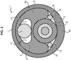
- an optical cable 1 extends along a longitudinal axis (perpendicular to the figure).
- the optical cable 1 comprises an optical element 2, a sheath 4 and a reinforcement 6.
- optical element an optical module including one or more optical fibers, tubes containing one or more optical fibers, optical fibers provided with an envelope, bare optical fibers or any other elements allowing the transmission of optical signals.
- the optical element 2 extends parallel to the longitudinal axis.
- the optical element 2 typically has a circular cross section.
- the optical element 2 comprises a semi-tight optical fiber 8 having a diameter equal to 900 micrometers, and a sheath 10 having an outer diameter of 2.3 millimeters surrounding the optical fiber 8.
- the sheath 10 of the optical element 2 can be made of an LSOH material (material with a low rate of smoke release and virtually no release of halogenated gases) for example filled Polyethylene or Polypropylene.
- Optical element 2 may also include aramid yarns (not shown).
- the reinforcement 6 also extends along the longitudinal axis of the optical cable.
- the reinforcement 6 defines a groove open longitudinally along this axis.
- the optical element 2 is at least partially received in the groove.
- the reinforcement 6 has a cross section to the longitudinal axis of the optical cable of the optical cable 1 in the form of C, as shown in figure 1 .
- One function of the reinforcement 6 is to stiffen the optical cable 1. It makes it possible to limit the expansions and shrinkages of the sheath 4 under the effect of temperature variations, thanks to its mechanical strength.
- Another function of the reinforcement 6 is to protect the optical element 2 against shocks.
- Reinforcement 6 comprises a cylindrical outer surface with generatrices parallel to the longitudinal axis of optical cable 1.
- the reinforcement 6 comprises a plastic material, for example low density polyethylene (LDPE) and/or fiber reinforced plastic (FRP). Its structure is composite.
- the fibers can be synthetic or natural in nature. These fibers can be bonded together by a thermosetting or thermoplastic resin.
- the reinforcement 6 consists of a rigid element 7 made for example of FRP extending parallel to the longitudinal axis of the optical cable of the optical cable 1, and a base 9 surrounding the rigid element 7, this base being made for example of LDPE.
- the base 9 defines a longitudinal passage of circular section in which the rigid element 7 is received.
- the reinforcement 6 also comprises flexible elements 11, 13 (that is to say comparatively more flexible than the rigid element 7), for example two rovings of aramid also extending in this passage.
- the passage is in this case not of circular section, but of substantially trapezoidal section with a rounded edge.
- sheath 4 is annular and extends around the longitudinal axis of optical cable 1.
- the sheath 4 extends around the optical element 2 and around the reinforcement 6.
- the sheath 4 is in one piece. It is for example made of high density polyethylene (HDPE).
- HDPE high density polyethylene
- Sheath 4 comprises a first part 4a and a second part 4b.
- the two parts 4a and 4b each extend over different angular sectors around the longitudinal axis of the optical cable 1.
- the two parts 4a and 4b are separated by two dotted lines crossing the sheath 4.
- the first part 4a is arranged facing the optical element 2.
- the expression “facing” means the fact that no element is interposed between the first part 4a of the sheath 4 and the optical element 2 , which means that if the first part 4a of the sheath 4 were removed, the optical element 2 would be visible and accessible from outside the optical cable 1.
- the first part 4a is not fixed to the optical element 2 nor to the reinforcement 6.
- the second part 4b of the sheath 4 is opposite the first part 4a with respect to the optical element 2 and facing the reinforcement 6.
- the reinforcement 6 and the optical element 2 at least partially received in the groove are arranged between the first part 4a and the second part 4b.
- the reinforcement 6 is fixed relative to the second part 4b of the sheath 4.
- the reinforcement 6 is for example glued to the second part 4b of the sheath 4.
- the reinforcement 6 is made of a plastic material comprising a glue-type additive. The bonding of the reinforcement 6 to the second part 4b of the sheath 4 is carried out during the extrusion of the sheath 4.
- a longitudinal cavity is formed in the optical cable 1 between the reinforcement 6 and the first part of the sheath 4.
- This longitudinal cavity comprises in particular the groove defined by the reinforcement 6.
- the longitudinal cavity is for example dimensioned so that the optical element 2 received in the groove touches the second part of the sheath 4.
- Two housings 12, 14 are also defined by the sheath 4 and the reinforcement 6.
- These two housings 12, 14 are two remaining spaces of the longitudinal cavity, once the optical element 2 is at least partially received in the groove of the reinforcement 6.
- the groove and the two housings 12, 14 form different parts of one and the same cavity.
- This cavity is defined by the first part 4a of the sheath.
- These two housings 12, 14 are arranged between the reinforcement 6 and the first part 4a of the sheath 4.
- optical element 2 is arranged between the two housings 12 and 14.
- the two housings 12 and 14 extend parallel to the longitudinal axis of the optical cable 1.
- the two housings 12 and 14 are separate from each other.
- the two housings 12, 14 are arranged so that the first part 4a of the sheath 4 (not attached to the reinforcement) extends over an angular sector of less than 180 degrees around the longitudinal axis of the optical cable of the cable .
- the optical cable 1 also comprises two tearing elements 16, 18 housed in the two housings (one tearing element per housing). Sheath 4 is arranged around tearing elements 16, 18.
- the two tearing elements 16, 18 are arranged to tear the sheath 4 when these tearing elements 16, 18 are pulled towards the outside of the sheath 4, so as to form in the first part 4a of the sheath 4 a tab delimited by the two tears, this tab being able to be moved away from the second part of the sheath 4 to free access to the optical element 2 from the outside of the optical cable 1.
- the two housings 12 and 14 are separated from each other by the optical element 2. This thus makes it possible to improve the confinement of the two tearing elements 16 and 18, and therefore to better guide a tearing of the sheath 4 by one or the other of these two tearing elements.
- the tearing elements 16, 18 are not glued to the sheath 4, which makes it easier for a user to grasp them.
- housings 12, 14 are dimensioned to block the tearing elements 16, 18 in translation parallel to the longitudinal axis of the optical cable 1, with respect to the sheath 4.
- the sheath 4, the reinforcement 6 and the element optical 2 press enough on each tearing element to prevent it from moving along the longitudinal axis relative to the sheath 4.
- the two housings 12, 14 make it possible to guide the tearing of the sheath 4 by the two tearing elements 16, 18.
- the two tearing elements 16, 18 extend generally straight when received in housings 12 and 14, and held under pressure.
- At least one of the tearing elements 16, 18 is made of a flexible material such as aramid.
- Aramid has the advantage of participating in the good tensile strength of the cable, in addition to allowing tearing of the sheath 4.
- At least one of the tearing elements 16, 18 is for example in the form of a wick (that is to say a set of substantially parallel fibers, for example made of aramid).
- This wick shape has the advantage of allowing a tearing element 16, 18 to naturally follow the edges of its housing 12, 14, by natural reorganization of the fibers which compose it. This makes it possible to improve the longitudinal locking effect of the tearing elements provided by the housings 12, 14.
- At least one tearing element has the form of a tearing rope made up of twisted fibers.
- a user makes tear initiators in an end portion of the sheath 4, for example by means of a cutting tool such as a cutter or a pair of scissors, so as to release portions of end of the two tearing elements 16, 18 housed in the housings 12, 14.
- a cutting tool such as a cutter or a pair of scissors
- the tearing elements 16 and 18 are not glued to the reinforcement 6, to the sheath 4 or to the optical element 2, their gripping by the user is facilitated.
- the housings 12 and 14 in which the tearing elements 16 and 18 are received are straight, these housings 12 and 14 naturally guide the tearing elements 16 and 18 into a perfectly straight position.
- the tearing elements 16 and 18 break the sheath 4 and form two tears therein. These two tears are located substantially at the level of the two dotted lines shown on the figure 1 And 2 , but can also be located elsewhere in the first part 4a of the sheath 4. Be that as it may, a tongue 20 is formed by these tears in the first part 4a of the sheath 4, this tongue 20 being delimited by and arranged between these two tears as shown in the picture 3 .
- the two tears delimiting this tab 20 are substantially rectilinear and parallel to the longitudinal axis of the optical cable 1 due to the fact that the tensioned tearing elements 16 and 18 have been guided by the housings 12 and 14 in a rectilinear position and parallel to this same longitudinal axis.
- the tongue 20 therefore has a substantially rectangular shape.
- the fact that the tongue 20 extends over an angular sector less than 180 degrees around the longitudinal axis of the optical cable 1 advantageously allows the tongue 20 to be moved away naturally from the second part 4b of the sheath 4 during the traction step, which releases access to the optical element without a subsequent step of manually separating the tab 20 by use being absolutely necessary.
- the fact that the tearing elements 16 and 18 are blocked longitudinally by an adequate dimensioning of the housings 12 and 14 makes it possible to ensure a tearing of the sheath 4 even when this sheath 4 is relatively thick (which requires exerting a significant traction on the tearing elements 16, 18).
- the user can manually move the tab 20 away from the second part 4b of the sheath 4, as if peeling the skin of a banana, so as to free up greater access to the optical element 2.
- the user does not need to remove another element which would be interposed between the tongue 20 and the optical element 2, since the first part 4a of the sheath 4 in which the tongue 20 is formed is opposite the optical element 2. Access to the optical element 2 is therefore particularly fast.
- the fact that the housings 12, 14 are parallel to the longitudinal axis of the optical cable 1 makes it possible to tear the sheath 4 over a very long length. Consequently, the optical element 2 is itself revealed over a great length, which has the advantage of facilitating its subsequent connection.
- This connection can be made by laying in a trunking, stapling or gluing up to a subscriber's optical socket in the case of the two previous embodiments.
- the cable according to the invention is not exclusively intended to be the subject of such a connection.
- the invention relates to any application requiring access to the optical element 2 surrounded by the sheath 4.
Landscapes
- Physics & Mathematics (AREA)
- General Physics & Mathematics (AREA)
- Optics & Photonics (AREA)
- Light Guides In General And Applications Therefor (AREA)
- Insulated Conductors (AREA)
- Communication Cables (AREA)
Claims (11)
- Optisches Kabel (1), umfassend:• eine Verstärkung (6), die eine Längsnut definiert, die sich parallel zu einer Längsachse des optischen Kabels (1) erstreckt,• ein optisches Element (2), das mindestens teilweise in der Nut aufgenommen ist,• einen Mantel (4), der das optische Element (2) und die Verstärkung (6) umgibt, wobei der Mantel (4) einen ersten Teil (4a), der dem optischen Element (2) zugewandt ist, und einen zweiten Teil (4b) gegenüber dem ersten Teil (4a) im Verhältnis zum optischen Element (2) und zur Verstärkung (6) umfasst,• zwei Reißelemente (16, 18), die zum Zerreißen des Mantels (4) geeignet sind, wenn die Reißelemente (16, 18) nach außerhalb des optischen Kabels (1) gezogen werden,• zwei Aufnahmen (12, 14), die von dem Mantel (4) und der Verstärkung (6) definiert sind, in denen die Reißelemente (16, 18) untergebracht sind, wobei die Aufnahmen (12, 14) eingerichtet sind, damit das Zerreißen des Mantels (4) durch die zwei Reißelemente (16, 18) im ersten Teil (4a) des Mantels (4) eine Lasche (20) bildet, die vom zweiten Teil (4b) des Mantels (4) derart beabstandbar ist, dass ein Zugang zum optischen Element von außerhalb des optischen Kabels (1) freigegeben wird, dadurch gekennzeichnet, dass die Nut und die zwei Aufnahmen verschiedene Teile ein und desselben Hohlraums bilden.
- Optisches Kabel (1) nach Anspruch 1, wobei sich die zwei Aufnahmen (12, 14) parallel zu einer Längsachse des optischen Kabels (1) erstrecken, damit die Lasche (20) von zwei zur Längsachse des optischen Kabels (1) parallelen Rissen begrenzt ist.
- Optisches Kabel (1) nach einem der Ansprüche 1 und 2, wobei die zwei Aufnahmen (12, 14) eingerichtet sind, damit sich die Lasche (20) über einen Winkelsektor von weniger als 180 Grad um die Längsachse des optischen Kabels (1) erstreckt.
- Optisches Kabel (1) nach einem der Ansprüche 1 bis 3, wobei die Verstärkung im Verhältnis zum zweiten Teil (4b) des Mantels (4) befestigt ist.
- Optisches Kabel (1) nach einem der Ansprüche 1 bis 4, wobei die Verstärkung (6) einen C-förmigen Querschnitt aufweist.
- Optisches Kabel (1) nach einem der Ansprüche 1 bis 5, wobei die Verstärkung (6) mindestens ein Kunststoffmaterial, beispielsweise Polyethylen niederer Dichte und/oder faserverstärkten Kunststoff, umfasst.
- Optisches Kabel (1) nach einem der Ansprüche 1 bis 6, wobei die Aufnahmen (12, 14) bemessen sind, um die Reißelemente (16, 18) in Translation parallel zur Längsachse des optischen Kabels (1) zu begrenzen, wobei die Reißelemente nicht mit dem Mantel (4) und/oder der Verstärkung (6) verklebt sind.
- Optisches Kabel (1) nach einem der Ansprüche 1 bis 7, wobei mindestens eins der Reißelemente (16, 18) die Form einer Schnur hat, die von etwa parallelen Fasern gebildet ist.
- Optisches Kabel (1) nach einem der Ansprüche 1 bis 8, wobei die zwei Aufnahmen (12, 14) durch das optische Element (2) voneinander getrennt sind.
- Verfahren zum Öffnen eines optischen Kabels (1), das eine Verstärkung (6), die eine Längsnut definiert, die sich parallel zu einer Längsachse des optischen Kabels (1) erstreckt, ein optisches Element (2), das mindestens teilweise in der Nut aufgenommen ist, einen Mantel (4), der das optische Element (2) umgibt und die Verstärkung (6) umfasst, wobei der Mantel (4) einen ersten Teil (4a), der dem optischen Element (2) zugewandt ist, und einen zweiten Teil (4b) gegenüber dem ersten Teil (4a) im Verhältnis zum optischen Element (2) und zur Verstärkung (6) umfasst, wobei das optische Kabel (1) ferner zwei Reißelemente (16, 18) und zwei Aufnahmen (12, 14) umfasst, die vom Mantel (4) und der Verstärkung (6) definiert sind, in denen die Reißelemente (16, 18) untergebracht sind, wobei das Verfahren ein Ziehen der Reißelemente (16, 18) nach außerhalb des optischen Kabels (1) derart umfasst, dass der Mantel (4) zerrissen wird und im ersten Teil des Mantels eine Lasche (20) gebildet wird, die vom zweiten Teil (4b) des Mantels und der Verstärkung (6) derart beabstandbar ist, dass ein Zugang zum optischen Element (2) von außerhalb des optischen Kabels (1) freigegeben wird.
- Verfahren nach Anspruch 10, wobei die zwei Reißelemente (16, 18) gleichzeitig gezogen werden.
Applications Claiming Priority (2)
| Application Number | Priority Date | Filing Date | Title |
|---|---|---|---|
| FR1762772A FR3075992B1 (fr) | 2017-12-21 | 2017-12-21 | Cable optique a elements de dechirements |
| PCT/FR2018/053400 WO2019122708A1 (fr) | 2017-12-21 | 2018-12-19 | Cable optique a elements de dechirements |
Publications (2)
| Publication Number | Publication Date |
|---|---|
| EP3729156A1 EP3729156A1 (de) | 2020-10-28 |
| EP3729156B1 true EP3729156B1 (de) | 2023-05-10 |
Family
ID=62749027
Family Applications (1)
| Application Number | Title | Priority Date | Filing Date |
|---|---|---|---|
| EP18845437.5A Active EP3729156B1 (de) | 2017-12-21 | 2018-12-19 | Optisches kabel mit ripcords |
Country Status (5)
| Country | Link |
|---|---|
| EP (1) | EP3729156B1 (de) |
| ES (1) | ES2945158T3 (de) |
| FR (1) | FR3075992B1 (de) |
| MA (1) | MA51322A (de) |
| WO (1) | WO2019122708A1 (de) |
Cited By (1)
| Publication number | Priority date | Publication date | Assignee | Title |
|---|---|---|---|---|
| CN119200121A (zh) * | 2024-11-28 | 2024-12-27 | 深圳市特发信息光网科技股份有限公司 | 一种余长稳定的光缆 |
Families Citing this family (1)
| Publication number | Priority date | Publication date | Assignee | Title |
|---|---|---|---|---|
| CN120469021B (zh) * | 2025-07-11 | 2025-09-26 | 四川天府江东科技有限公司 | 一种防光纤扭转过度的易撕裂蝶形光缆 |
Citations (1)
| Publication number | Priority date | Publication date | Assignee | Title |
|---|---|---|---|---|
| US20060140557A1 (en) * | 2001-03-30 | 2006-06-29 | Parris Donald R | Fiber optic cable with strength member formed from a sheet |
Family Cites Families (5)
| Publication number | Priority date | Publication date | Assignee | Title |
|---|---|---|---|---|
| GB2343014A (en) * | 1998-10-23 | 2000-04-26 | Bowthorpe Plc | Optic fibre cable |
| US6618526B2 (en) * | 2001-09-27 | 2003-09-09 | Corning Cable Systems Llc | Fiber optic cables |
| JP5351503B2 (ja) | 2008-03-07 | 2013-11-27 | 株式会社フジクラ | 光ファイバケーブル及びその光ファイバケーブルにおける口出し方法 |
| US8913862B1 (en) * | 2013-09-27 | 2014-12-16 | Corning Optical Communications LLC | Optical communication cable |
| FR3044776B1 (fr) * | 2015-12-07 | 2018-04-06 | Acome Societe Cooperative Et Participative Societe Anonyme Cooperative De Production A Capital Variable | Cable optique a element de renfort mecanique |
-
2017
- 2017-12-21 FR FR1762772A patent/FR3075992B1/fr active Active
-
2018
- 2018-12-19 EP EP18845437.5A patent/EP3729156B1/de active Active
- 2018-12-19 ES ES18845437T patent/ES2945158T3/es active Active
- 2018-12-19 WO PCT/FR2018/053400 patent/WO2019122708A1/fr not_active Ceased
- 2018-12-19 MA MA051322A patent/MA51322A/fr unknown
Patent Citations (1)
| Publication number | Priority date | Publication date | Assignee | Title |
|---|---|---|---|---|
| US20060140557A1 (en) * | 2001-03-30 | 2006-06-29 | Parris Donald R | Fiber optic cable with strength member formed from a sheet |
Cited By (2)
| Publication number | Priority date | Publication date | Assignee | Title |
|---|---|---|---|---|
| CN119200121A (zh) * | 2024-11-28 | 2024-12-27 | 深圳市特发信息光网科技股份有限公司 | 一种余长稳定的光缆 |
| CN119200121B (zh) * | 2024-11-28 | 2025-04-11 | 深圳市特发信息光网科技股份有限公司 | 一种余长稳定的光缆 |
Also Published As
| Publication number | Publication date |
|---|---|
| FR3075992B1 (fr) | 2022-09-09 |
| EP3729156A1 (de) | 2020-10-28 |
| WO2019122708A1 (fr) | 2019-06-27 |
| MA51322A (fr) | 2021-03-31 |
| FR3075992A1 (fr) | 2019-06-28 |
| ES2945158T3 (es) | 2023-06-28 |
Similar Documents
| Publication | Publication Date | Title |
|---|---|---|
| EP0011561B1 (de) | Verfahren zum Anbringen einer optischen Faser in einer Verbindungszwinge | |
| EP0864896B1 (de) | Optische Einheit für ein Faseroptischeskabel | |
| EP0441676B1 (de) | Stecker für optische Fasern | |
| FR2915002A1 (fr) | Procede d'acces a une ou plusieurs fibres optiques d'un cable de telecommunication | |
| EP0063068B1 (de) | Verfahren zur konzentrischen Montage einer optischen Faser in einem Anschlussstück | |
| EP0720034A1 (de) | Optisches Kabel und Verfahren zu seiner Fabrikation | |
| EP3729156B1 (de) | Optisches kabel mit ripcords | |
| EP2898358B1 (de) | Vorrichtung mit einem flüssigen kern umfassenden lichtwellenleiter und verwandtes fertigungsverfahren | |
| EP1972978B1 (de) | Optisches Kabel zum Anschluss an ein allgemeines Verteilernetz und Anschlussverfahren dieses Kabels | |
| FR3024922A1 (fr) | Gaine tubulaire annelee a bande longitudinale detachable | |
| EP3035098B1 (de) | Verzweigungsvorrichtung eines optischen kabels | |
| EP0084984B1 (de) | Vorrichtung zur Herstellung einer Extremitätenebene optischer Fasern, die rund um eine axialsymmetrische Struktur verteilt sind | |
| FR2672652A1 (fr) | Systeme d'amortissement notamment pour systemes d'arme. | |
| EP0855721B1 (de) | Faseroptisches Kabel | |
| FR2512218A1 (fr) | Connecteur de fibres optiques | |
| EP2226664A1 (de) | Schneidwerkzeug für Hülle eines Verbindungskabels | |
| EP2791723B1 (de) | Optisches kabel mit abnehmbaren mikromodulen und einem inneren längenprofilelement | |
| EP1049947A1 (de) | Verbinder für zwei optische fasern mit haltevorrichtung in achsrichtung und mit werkzeug zum lösen der verbindung | |
| FR2745962A1 (fr) | Gaine annelee fendue a protection phonique | |
| FR2745393A1 (fr) | Dispositif de support d'epissures, notamment pour fibres ou modules optiques | |
| EP3387474A1 (de) | Optisches kabel mit einem mechanischen verstärkungselement | |
| FR2515887A1 (fr) | Dispositif destine au tirage d'un cable dans une conduite et procede de tirage | |
| FR2750220A1 (fr) | Boitier de protection d'epissures, de repartition, de confinement et de stockage, des fibres optiques d'un cable de distribution | |
| CA3122859A1 (fr) | Canne a peche telescopique a fil interieur | |
| WO2006072751A1 (fr) | Dispositif de raccordement etanche de cables de telecommunications et son procede de fabrication |
Legal Events
| Date | Code | Title | Description |
|---|---|---|---|
| STAA | Information on the status of an ep patent application or granted ep patent |
Free format text: STATUS: UNKNOWN |
|
| STAA | Information on the status of an ep patent application or granted ep patent |
Free format text: STATUS: THE INTERNATIONAL PUBLICATION HAS BEEN MADE |
|
| PUAI | Public reference made under article 153(3) epc to a published international application that has entered the european phase |
Free format text: ORIGINAL CODE: 0009012 |
|
| STAA | Information on the status of an ep patent application or granted ep patent |
Free format text: STATUS: REQUEST FOR EXAMINATION WAS MADE |
|
| 17P | Request for examination filed |
Effective date: 20200717 |
|
| AK | Designated contracting states |
Kind code of ref document: A1 Designated state(s): AL AT BE BG CH CY CZ DE DK EE ES FI FR GB GR HR HU IE IS IT LI LT LU LV MC MK MT NL NO PL PT RO RS SE SI SK SM TR |
|
| AX | Request for extension of the european patent |
Extension state: BA ME |
|
| DAX | Request for extension of the european patent (deleted) | ||
| RAV | Requested validation state of the european patent: fee paid |
Extension state: TN Effective date: 20200717 Extension state: MA Effective date: 20200717 |
|
| GRAP | Despatch of communication of intention to grant a patent |
Free format text: ORIGINAL CODE: EPIDOSNIGR1 |
|
| STAA | Information on the status of an ep patent application or granted ep patent |
Free format text: STATUS: GRANT OF PATENT IS INTENDED |
|
| INTG | Intention to grant announced |
Effective date: 20230102 |
|
| GRAS | Grant fee paid |
Free format text: ORIGINAL CODE: EPIDOSNIGR3 |
|
| GRAA | (expected) grant |
Free format text: ORIGINAL CODE: 0009210 |
|
| STAA | Information on the status of an ep patent application or granted ep patent |
Free format text: STATUS: THE PATENT HAS BEEN GRANTED |
|
| AK | Designated contracting states |
Kind code of ref document: B1 Designated state(s): AL AT BE BG CH CY CZ DE DK EE ES FI FR GB GR HR HU IE IS IT LI LT LU LV MC MK MT NL NO PL PT RO RS SE SI SK SM TR |
|
| REG | Reference to a national code |
Ref country code: GB Ref legal event code: FG4D Free format text: NOT ENGLISH |
|
| REG | Reference to a national code |
Ref country code: AT Ref legal event code: REF Ref document number: 1567239 Country of ref document: AT Kind code of ref document: T Effective date: 20230515 Ref country code: CH Ref legal event code: EP |
|
| REG | Reference to a national code |
Ref country code: DE Ref legal event code: R096 Ref document number: 602018049774 Country of ref document: DE |
|
| REG | Reference to a national code |
Ref country code: IE Ref legal event code: FG4D Free format text: LANGUAGE OF EP DOCUMENT: FRENCH |
|
| P01 | Opt-out of the competence of the unified patent court (upc) registered |
Effective date: 20230427 |
|
| REG | Reference to a national code |
Ref country code: ES Ref legal event code: FG2A Ref document number: 2945158 Country of ref document: ES Kind code of ref document: T3 Effective date: 20230628 |
|
| REG | Reference to a national code |
Ref country code: LT Ref legal event code: MG9D |
|
| REG | Reference to a national code |
Ref country code: NL Ref legal event code: MP Effective date: 20230510 |
|
| REG | Reference to a national code |
Ref country code: AT Ref legal event code: MK05 Ref document number: 1567239 Country of ref document: AT Kind code of ref document: T Effective date: 20230510 |
|
| PG25 | Lapsed in a contracting state [announced via postgrant information from national office to epo] |
Ref country code: SE Free format text: LAPSE BECAUSE OF FAILURE TO SUBMIT A TRANSLATION OF THE DESCRIPTION OR TO PAY THE FEE WITHIN THE PRESCRIBED TIME-LIMIT Effective date: 20230510 Ref country code: PT Free format text: LAPSE BECAUSE OF FAILURE TO SUBMIT A TRANSLATION OF THE DESCRIPTION OR TO PAY THE FEE WITHIN THE PRESCRIBED TIME-LIMIT Effective date: 20230911 Ref country code: NO Free format text: LAPSE BECAUSE OF FAILURE TO SUBMIT A TRANSLATION OF THE DESCRIPTION OR TO PAY THE FEE WITHIN THE PRESCRIBED TIME-LIMIT Effective date: 20230810 Ref country code: NL Free format text: LAPSE BECAUSE OF FAILURE TO SUBMIT A TRANSLATION OF THE DESCRIPTION OR TO PAY THE FEE WITHIN THE PRESCRIBED TIME-LIMIT Effective date: 20230510 Ref country code: AT Free format text: LAPSE BECAUSE OF FAILURE TO SUBMIT A TRANSLATION OF THE DESCRIPTION OR TO PAY THE FEE WITHIN THE PRESCRIBED TIME-LIMIT Effective date: 20230510 |
|
| PG25 | Lapsed in a contracting state [announced via postgrant information from national office to epo] |
Ref country code: RS Free format text: LAPSE BECAUSE OF FAILURE TO SUBMIT A TRANSLATION OF THE DESCRIPTION OR TO PAY THE FEE WITHIN THE PRESCRIBED TIME-LIMIT Effective date: 20230510 Ref country code: PL Free format text: LAPSE BECAUSE OF FAILURE TO SUBMIT A TRANSLATION OF THE DESCRIPTION OR TO PAY THE FEE WITHIN THE PRESCRIBED TIME-LIMIT Effective date: 20230510 Ref country code: LV Free format text: LAPSE BECAUSE OF FAILURE TO SUBMIT A TRANSLATION OF THE DESCRIPTION OR TO PAY THE FEE WITHIN THE PRESCRIBED TIME-LIMIT Effective date: 20230510 Ref country code: LT Free format text: LAPSE BECAUSE OF FAILURE TO SUBMIT A TRANSLATION OF THE DESCRIPTION OR TO PAY THE FEE WITHIN THE PRESCRIBED TIME-LIMIT Effective date: 20230510 Ref country code: IS Free format text: LAPSE BECAUSE OF FAILURE TO SUBMIT A TRANSLATION OF THE DESCRIPTION OR TO PAY THE FEE WITHIN THE PRESCRIBED TIME-LIMIT Effective date: 20230910 Ref country code: HR Free format text: LAPSE BECAUSE OF FAILURE TO SUBMIT A TRANSLATION OF THE DESCRIPTION OR TO PAY THE FEE WITHIN THE PRESCRIBED TIME-LIMIT Effective date: 20230510 Ref country code: GR Free format text: LAPSE BECAUSE OF FAILURE TO SUBMIT A TRANSLATION OF THE DESCRIPTION OR TO PAY THE FEE WITHIN THE PRESCRIBED TIME-LIMIT Effective date: 20230811 |
|
| PG25 | Lapsed in a contracting state [announced via postgrant information from national office to epo] |
Ref country code: FI Free format text: LAPSE BECAUSE OF FAILURE TO SUBMIT A TRANSLATION OF THE DESCRIPTION OR TO PAY THE FEE WITHIN THE PRESCRIBED TIME-LIMIT Effective date: 20230510 |
|
| PG25 | Lapsed in a contracting state [announced via postgrant information from national office to epo] |
Ref country code: SK Free format text: LAPSE BECAUSE OF FAILURE TO SUBMIT A TRANSLATION OF THE DESCRIPTION OR TO PAY THE FEE WITHIN THE PRESCRIBED TIME-LIMIT Effective date: 20230510 |
|
| PG25 | Lapsed in a contracting state [announced via postgrant information from national office to epo] |
Ref country code: SM Free format text: LAPSE BECAUSE OF FAILURE TO SUBMIT A TRANSLATION OF THE DESCRIPTION OR TO PAY THE FEE WITHIN THE PRESCRIBED TIME-LIMIT Effective date: 20230510 Ref country code: SK Free format text: LAPSE BECAUSE OF FAILURE TO SUBMIT A TRANSLATION OF THE DESCRIPTION OR TO PAY THE FEE WITHIN THE PRESCRIBED TIME-LIMIT Effective date: 20230510 Ref country code: RO Free format text: LAPSE BECAUSE OF FAILURE TO SUBMIT A TRANSLATION OF THE DESCRIPTION OR TO PAY THE FEE WITHIN THE PRESCRIBED TIME-LIMIT Effective date: 20230510 Ref country code: EE Free format text: LAPSE BECAUSE OF FAILURE TO SUBMIT A TRANSLATION OF THE DESCRIPTION OR TO PAY THE FEE WITHIN THE PRESCRIBED TIME-LIMIT Effective date: 20230510 Ref country code: DK Free format text: LAPSE BECAUSE OF FAILURE TO SUBMIT A TRANSLATION OF THE DESCRIPTION OR TO PAY THE FEE WITHIN THE PRESCRIBED TIME-LIMIT Effective date: 20230510 Ref country code: CZ Free format text: LAPSE BECAUSE OF FAILURE TO SUBMIT A TRANSLATION OF THE DESCRIPTION OR TO PAY THE FEE WITHIN THE PRESCRIBED TIME-LIMIT Effective date: 20230510 |
|
| REG | Reference to a national code |
Ref country code: DE Ref legal event code: R097 Ref document number: 602018049774 Country of ref document: DE |
|
| PLBE | No opposition filed within time limit |
Free format text: ORIGINAL CODE: 0009261 |
|
| STAA | Information on the status of an ep patent application or granted ep patent |
Free format text: STATUS: NO OPPOSITION FILED WITHIN TIME LIMIT |
|
| 26N | No opposition filed |
Effective date: 20240213 |
|
| PG25 | Lapsed in a contracting state [announced via postgrant information from national office to epo] |
Ref country code: SI Free format text: LAPSE BECAUSE OF FAILURE TO SUBMIT A TRANSLATION OF THE DESCRIPTION OR TO PAY THE FEE WITHIN THE PRESCRIBED TIME-LIMIT Effective date: 20230510 |
|
| PG25 | Lapsed in a contracting state [announced via postgrant information from national office to epo] |
Ref country code: SI Free format text: LAPSE BECAUSE OF FAILURE TO SUBMIT A TRANSLATION OF THE DESCRIPTION OR TO PAY THE FEE WITHIN THE PRESCRIBED TIME-LIMIT Effective date: 20230510 |
|
| REG | Reference to a national code |
Ref country code: CH Ref legal event code: PL |
|
| PG25 | Lapsed in a contracting state [announced via postgrant information from national office to epo] |
Ref country code: LU Free format text: LAPSE BECAUSE OF NON-PAYMENT OF DUE FEES Effective date: 20231219 |
|
| PG25 | Lapsed in a contracting state [announced via postgrant information from national office to epo] |
Ref country code: MC Free format text: LAPSE BECAUSE OF FAILURE TO SUBMIT A TRANSLATION OF THE DESCRIPTION OR TO PAY THE FEE WITHIN THE PRESCRIBED TIME-LIMIT Effective date: 20230510 |
|
| PG25 | Lapsed in a contracting state [announced via postgrant information from national office to epo] |
Ref country code: MC Free format text: LAPSE BECAUSE OF FAILURE TO SUBMIT A TRANSLATION OF THE DESCRIPTION OR TO PAY THE FEE WITHIN THE PRESCRIBED TIME-LIMIT Effective date: 20230510 Ref country code: LU Free format text: LAPSE BECAUSE OF NON-PAYMENT OF DUE FEES Effective date: 20231219 |
|
| PG25 | Lapsed in a contracting state [announced via postgrant information from national office to epo] |
Ref country code: CH Free format text: LAPSE BECAUSE OF NON-PAYMENT OF DUE FEES Effective date: 20231231 |
|
| PG25 | Lapsed in a contracting state [announced via postgrant information from national office to epo] |
Ref country code: CH Free format text: LAPSE BECAUSE OF NON-PAYMENT OF DUE FEES Effective date: 20231231 |
|
| PG25 | Lapsed in a contracting state [announced via postgrant information from national office to epo] |
Ref country code: BG Free format text: LAPSE BECAUSE OF FAILURE TO SUBMIT A TRANSLATION OF THE DESCRIPTION OR TO PAY THE FEE WITHIN THE PRESCRIBED TIME-LIMIT Effective date: 20230510 |
|
| PG25 | Lapsed in a contracting state [announced via postgrant information from national office to epo] |
Ref country code: BG Free format text: LAPSE BECAUSE OF FAILURE TO SUBMIT A TRANSLATION OF THE DESCRIPTION OR TO PAY THE FEE WITHIN THE PRESCRIBED TIME-LIMIT Effective date: 20230510 |
|
| PG25 | Lapsed in a contracting state [announced via postgrant information from national office to epo] |
Ref country code: CY Free format text: LAPSE BECAUSE OF FAILURE TO SUBMIT A TRANSLATION OF THE DESCRIPTION OR TO PAY THE FEE WITHIN THE PRESCRIBED TIME-LIMIT; INVALID AB INITIO Effective date: 20181219 |
|
| PG25 | Lapsed in a contracting state [announced via postgrant information from national office to epo] |
Ref country code: HU Free format text: LAPSE BECAUSE OF FAILURE TO SUBMIT A TRANSLATION OF THE DESCRIPTION OR TO PAY THE FEE WITHIN THE PRESCRIBED TIME-LIMIT; INVALID AB INITIO Effective date: 20181219 |
|
| VS25 | Lapsed in a validation state [announced via postgrant information from nat. office to epo] |
Ref country code: MA Free format text: FAILURE TO ELECT DOMICILE IN THE NATIONAL COUNTRY Effective date: 20230811 |
|
| PG25 | Lapsed in a contracting state [announced via postgrant information from national office to epo] |
Ref country code: TR Free format text: LAPSE BECAUSE OF FAILURE TO SUBMIT A TRANSLATION OF THE DESCRIPTION OR TO PAY THE FEE WITHIN THE PRESCRIBED TIME-LIMIT Effective date: 20230510 |
|
| PGFP | Annual fee paid to national office [announced via postgrant information from national office to epo] |
Ref country code: GB Payment date: 20251229 Year of fee payment: 8 |
|
| PGFP | Annual fee paid to national office [announced via postgrant information from national office to epo] |
Ref country code: IT Payment date: 20251210 Year of fee payment: 8 |
|
| PGFP | Annual fee paid to national office [announced via postgrant information from national office to epo] |
Ref country code: FR Payment date: 20251230 Year of fee payment: 8 |
|
| PGFP | Annual fee paid to national office [announced via postgrant information from national office to epo] |
Ref country code: BE Payment date: 20251226 Year of fee payment: 8 |
|
| PGFP | Annual fee paid to national office [announced via postgrant information from national office to epo] |
Ref country code: IE Payment date: 20251126 Year of fee payment: 8 |
|
| PGFP | Annual fee paid to national office [announced via postgrant information from national office to epo] |
Ref country code: ES Payment date: 20260112 Year of fee payment: 8 |
|
| PGFP | Annual fee paid to national office [announced via postgrant information from national office to epo] |
Ref country code: DE Payment date: 20251231 Year of fee payment: 8 |