EP3729408B1 - Procédé, système et programme d'ordinateur pour la compensation des effets mécaniques de chargement de commande de simulateur - Google Patents
Procédé, système et programme d'ordinateur pour la compensation des effets mécaniques de chargement de commande de simulateur Download PDFInfo
- Publication number
- EP3729408B1 EP3729408B1 EP18827085.4A EP18827085A EP3729408B1 EP 3729408 B1 EP3729408 B1 EP 3729408B1 EP 18827085 A EP18827085 A EP 18827085A EP 3729408 B1 EP3729408 B1 EP 3729408B1
- Authority
- EP
- European Patent Office
- Prior art keywords
- force
- signal
- control
- generating
- compensation
- Prior art date
- Legal status (The legal status is an assumption and is not a legal conclusion. Google has not performed a legal analysis and makes no representation as to the accuracy of the status listed.)
- Active
Links
Images


Classifications
-
- G—PHYSICS
- G09—EDUCATION; CRYPTOGRAPHY; DISPLAY; ADVERTISING; SEALS
- G09B—EDUCATIONAL OR DEMONSTRATION APPLIANCES; APPLIANCES FOR TEACHING, OR COMMUNICATING WITH, THE BLIND, DEAF OR MUTE; MODELS; PLANETARIA; GLOBES; MAPS; DIAGRAMS
- G09B9/00—Simulators for teaching or training purposes
- G09B9/02—Simulators for teaching or training purposes for teaching control of vehicles or other craft
- G09B9/08—Simulators for teaching or training purposes for teaching control of vehicles or other craft for teaching control of aircraft, e.g. Link trainer
- G09B9/28—Simulation of stick forces or the like
-
- G—PHYSICS
- G09—EDUCATION; CRYPTOGRAPHY; DISPLAY; ADVERTISING; SEALS
- G09B—EDUCATIONAL OR DEMONSTRATION APPLIANCES; APPLIANCES FOR TEACHING, OR COMMUNICATING WITH, THE BLIND, DEAF OR MUTE; MODELS; PLANETARIA; GLOBES; MAPS; DIAGRAMS
- G09B9/00—Simulators for teaching or training purposes
-
- G—PHYSICS
- G09—EDUCATION; CRYPTOGRAPHY; DISPLAY; ADVERTISING; SEALS
- G09B—EDUCATIONAL OR DEMONSTRATION APPLIANCES; APPLIANCES FOR TEACHING, OR COMMUNICATING WITH, THE BLIND, DEAF OR MUTE; MODELS; PLANETARIA; GLOBES; MAPS; DIAGRAMS
- G09B9/00—Simulators for teaching or training purposes
- G09B9/02—Simulators for teaching or training purposes for teaching control of vehicles or other craft
- G09B9/08—Simulators for teaching or training purposes for teaching control of vehicles or other craft for teaching control of aircraft, e.g. Link trainer
- G09B9/12—Motion systems for aircraft simulators
Definitions
- the present invention relates to simulators and more particularly to a method and system for compensating mechanical effects of control loading devices in simulators.
- Simulators of vehicle generally comprise a plurality of simulated controls which must reproduce the 'look and feel' of the corresponding real control in a real vehicle in terms of design, force feedback, frictions, dynamics behaviour and so. When achieved, this allows a pilot of the simulator to get a representative training as he would actually experience in the real vehicle.
- U.S.A. Patent 3,220,121 A from Culter and U.S.A. 3,463,866 A from Staples are examples of simulating apparatus for flight training.
- CLS Control Loading System
- the aim of the Control Loading System is to model the loading conditions and provide to the pilot feedback forces required on the control instruments (mainly on the yoke and pedals as the primary controls instruments).
- the Control Loading System is the sensitive human-machine interface in simulators that have a major impact on a successful training because it has to provide an authentic reproduction of what happens in the aircraft and a realistic simulation of failure modes.
- an actuator is fed with a signal computed in a feedback control loop taking into account the stick position and the measure by a force sensor of the force the pilot actually exerts on the flight control.
- the feedback control loop is generally a software simulated model of the real stick mechanics, dynamics and so on. Such model to reproduce the right feeling has to take into account the real aircraft system but also the simulator system. Furthermore, the system inertia is replaced by the aircraft real inertia to obtain the right force feedback.
- U.S.A. Patent 4,236,325 from Hall et al. discloses a feedback control loop employed in aircraft simulators.
- an inertia compensation is implemented which aim is to remove the inertia of the simulator control instruments.
- This force is then subtracted to the total sum of all the other forces (force sensor, frictions, force feedback...) that are applied to the system.
- the force subtraction the inertia due to the simulator control is removed and nearly identical dynamics can be obtained compared to the real aircraft, particularly when it comes to high dynamics.
- Another side effect of known inertia compensation approach is that it does not take into account the mechanical effects of the real simulated product (such as frictions, damping...) that are measured by the force sensor.
- the system has to take into account all the effects or forces that apply, not only the inertia effects. It does not take into account the force sensor dynamics either.
- the mechanical effect compensation forces to be subtracted must efficiently model the mechanical effects as seen by the force sensor before being subtracted.
- a control loader allows exerting a controlled force on a load target, the control loader having an actuator, a first force sensor, a second force sensor, and a control portion for controlling the actuator in response to the first and second sensors.
- the first force sensor is disposed to detect the external force exerted on the load target and is coupled to the mechanical linkages which transmit the forces from the actuator to the load target.
- the second force sensor is connected to the actuator to measure the force generated by the actuator.
- the control portion includes a desired response model for the control loader system.
- the signals from the first and second force sensors are input to the control portion, and the control portion generates a control signal to the actuator so that the actuator provides the desired response.
- a system response model portion determines the expected response of the simulator system itself to the force on the load target. The system response model portion compensates for the inertia, vibration, damping, friction, etc. of the control loader system itself in determining how the actuator should respond to the force.
- the desired response model portion generates an output as if the simulator itself had no mass, damping or spring loading. Since the simulator does have such characteristics, the system response model portion provides feed forward compensation for such factors.
- a system comprising means adapted for carrying out each step of the method according to the first aspect of the invention.
- a computer readable medium having encoded thereon a computer program comprising instructions for carrying out the steps of the method when the computer program is executed on a computer.
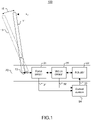
- FIG 1 a block diagram of a Control Loading System 100 for implementing the present invention is depicted in accordance with a preferred embodiment.
- the goal of the CLS is to reproduce with enough sense of fidelity the behavior of a desired system on a simulated control instrument.
- the CLS allows reproducing the behavior of a control stick (11) of an aircraft when a pilot trainee interacts with it by applying a force "F in " to the stick.
- control stick (11) can move along a trajectory (10) to an arbitrary position (12).
- a module (20) of mechanical components (21, 22, 23) of the Control Loading System is coupled to the control stick (11) by a junction (13).
- the control stick (11) is coupled to a force sensor (21) which outputs a force sensor signal (31) representative of the force exerted on the control stick (11).
- Force sensor signal (31) is input to a control system (34).
- Force sensor (21) is further coupled to a motion sensor (22) which allows measuring the motion of the system, i.e. measuring acceleration, velocity, position or any combination of these parameters.
- Motion sensor (22) outputs a motion signal (32) composed of any combination of acceleration, velocity and position parameters measured by motion sensor.
- Motion signal (32) is input to control system (34).
- Motion sensor (22) is further coupled to an actuator (23) which allows providing a force feedback according to specific control laws such as spring force or friction laws.
- actuator (23) is further coupled to control system (34) to receive as input a control signal (33) output from control system (34), the control signal being representative of a control command, composed of any combination of acceleration (or torque or force), velocity and position, to be executed by the actuator (23).
- actuator (23) is composed of an electrical motor with an encoder allowing grouping motion sensor (22) and actuator (23) in a single block.
- control system (34) generates control signal (33) based on motion signal (32) and force sensor signal (31).
- Control system (34) may be implemented as a CLS computing device dedicated to handle as inputs force sensor and motion signals (31, 32) and for computing as output control signal (33) representative of a command to be applied to actuator (23). Even if not represented, CLS computer may communicate with various external systems, such as host computers, cloud based network to name a few.
- motion signal (32) is any combination of acceleration parameter "A sensor ", velocity parameter “V sensor” and position parameter “X sensor “ that are measured by motion sensor (22).
- Motion signal (32) is fed to a desired response model module (42) and to a system response model module (41).
- the function of the desired response model module (42) is to provide a model of the desired system to reproduce.
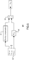
- the desired response model module (42) as detailed on figure 4 , allows representing the control stick mechanics including for example spring box (71), frictions (72), damping effects and other mechanical effects (not represented).
- the desired response model module (42) outputs a desired response force signal "F des "(52) representing the total force, after summing the forces in a summer (73), that would be exerted by the desired system.
- the force sensor signal (31) and motion signal (32) are fed to a system response model module (41) which function is to provide a model of the behavior of the mechanical components of the CLS as measured by the force sensor (21).
- the mechanical components behavior includes mechanical parts inertia, frictions, damping effects and other mechanical effects exerted by the system itself, including possible nonlinear effects and mechanical structure modification effects.
- the system response model module (41) outputs a system response force signal (51).
- Force sensor signal (31), desired response force signal (52) and system response force signal (51) are summed into a summer (43).
- the force sum signal (53) that is obtained represents the sum of all the forces that applies to the system.
- the system response model module (41) of the present invention represents the mechanical behavior of the system.
- the system response model module (41) of the present invention is configured with a precision allowing to have a force sum signal (53) that represents the force required for the actuator to move the system as if the desired response model alone would have move.
- the desired response model module is configured with enough fidelity compared to the desired system, the movement of the system thus obtained represents the desired system movement with said fidelity.
- the force sum signal (53) is amplified in an amplifier (44) which represents the mechanical inertia "M des " (or equivalent mass) of the desired response model module (i.e. the inertia of the desired system).
- the amplifier (44) outputs an acceleration control signal "A control ".
- the acceleration control signal may be integrated by an integrator (45) to provide a velocity control signal “V control ", and this latter may be integrated by an integrator (46) to provide a position control signal "X control ".
- the acceleration control signal, the velocity control signal and the position control signal may be used as part of the control signal (33) fed to command the actuator (23).
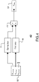
- FIG. 3 details the system response model module (41) of the present invention.
- Motion signal (32) composed of any combination of acceleration parameter "A sensor ", velocity parameter “V sensor” and position parameter “X sensor ", is fed to a system compensation model module (61) which function is to model the behavior of the mechanical components of mechanical module (20) of the CLS as they are measured by force sensor (21).
- System compensation model module (61) takes into account the force sensor dynamics (i.e. its transfer function).
- the system compensation model module (61) represents the behavior of the control stick and other mechanical components linked to it and interacting, namely: mechanical parts inertia, frictions, damping effects and other mechanical effects or forces exerted by the system itself, including possible nonlinear effects and mechanical structure modification effects, such as mechanical stops for example.
- System compensation model module (61) outputs a system compensation force signal "F sys " which is fed to a saturation device (62).
- Saturation device (62) outputs a saturated system response force signal "F sat “ (51).
- saturation device (62) saturates the system compensation force signal "F sys " to a range [-F sensor , +F sensor ].
- saturation device (62) ensures the system response model module (41) does not generate any active force which would lead to unwanted behavior of the system. Still advantageously, by saturating the system compensation force signal in a range depending on the force sensor signal, the saturation device (62) allows encompassing some implementations where a system compensation model module (61) would not reproduce with enough fidelity the behavior of the mechanical components of the system.
- a desired response model module (42) in the context of an aircraft simulator is described.
- the function of desired response model module (42) is to reproduce with great authenticity the mechanical effects of the control stick of a real aircraft.
- a real aircraft control stick or say a pitch axis of a helicopter, includes a spring box which defines the control stick rest position, and exerts an effort that a pilot feels whenever he pushes or pulls the stick. When the pilot releases the stick, this latter goes back on its own to the rest position thanks to the spring effect.
- a spring box (71) modelizes this spring effect or spring force based on the stick position "X sensor ".
- the pitch axis also includes frictions - dry and viscous frictions - that also apply to the stick. These frictions represent the friction forces appearing between mechanical components of the rods when they are moving. As such in the desired response model module of the present invention, a friction block (72) is in charge of modeling said friction forces as denoted "F friction ".
- acceleration parameter "A sensor” is not used to determine the force applying on the control stick.
- any combination of acceleration parameter "A sensor ", velocity parameter “V sensor “ and position parameter “X sensor” may be used to determine a force applying on any other control loading device.
- the force signals "F spring " and “F friction " obtained are summed into a summer (73) as per the Newton's 2 nd law applied to the control stick.
- the resulting desired response force signal “F des “ (52) models the force exerted by the real aircraft stick on the pilot hand.
- FIG. 5 a detailed system compensation model module (61) in accordance with an embodiment of the present invention is shown in the context of an aircraft simulator.
- the position signal representing the position parameter "X sensor " is fed to a gravity compensation module (81) which outputs a gravity compensation force signal representative of the gravitation force "F grav " applied to the simulator control stick based on its position.
- the gravitation force is obtained from a look up table filled with values measured experimentally directly on the simulator, using the force sensor value "F sensor " along with the position parameter "X sensor ".
- the amplifier output is an inertia compensation force signal representative of the force due to the inertia of the mechanical parts of the simulator control stick, thus constituting an inertia compensation.
- the gravity compensation force and the inertia compensation force are summed in a summer (83) to obtain a system compensation force represented by the system compensation force signal "F sys " which compensates the mechanical effects due to gravity and mechanical parts inertia of the simulated control stick.
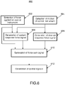
- Process 600 begins when feedback control loop is operating.
- a first step (602) the process allows detecting a force applied on the simulated control instrument and generating a force sensor signal.
- the process allows then detecting the motion parameters relative to the motion of the control instrument (604).
- the motion parameters cover acceleration, velocity and position of the control instrument resulting from motion of an actuator.
- the motion parameters allow computing a desired response force signal that represents the forces that would be exerted by the desired system to reproduce.
- the motion parameters are fed to a desired response model module which allows generating the desired response force signal.
- the motion parameters and the force sensor signal are used to generate a system response force signal (step 608) that represents the forces exerted by the behaviour of some mechanical parts of the system.
- a system response model module is used to generate the system response force signal.
- the system response model combines a system compensation model module representing the mechanical effects of the system with a saturation device that allows saturating the system compensation force signal to a saturation range determined by the force sensor signal.
- the process allows generating a force sum signal based on the desired response force signal, the system response force signal and the force sensor signal.
- control signals are obtained by determining the right part of the Newton's 2 nd law equation, i.e. determining the "a" term, with "a” being the system desired acceleration. From this acceleration, the desired velocity and the desired position of the system are computed.
- the control signals are composed of any combination of these three values (acceleration, velocity, position).
- the control signals may then be used to control an actuator that is in charge of executing the control signals to control the control instrument.
- the invention is implemented in software, which includes but is not limited to firmware, resident software, microcode.
- the invention can take the form of a computer program product accessible from a computer-usable or computer-readable medium providing program code for use by or in connection with a computer or any instruction execution system.
- a computer-usable or computer readable medium can be any apparatus that can contain, store, communicate, propagate, or transport the program for use by or in connection with the instruction execution system, apparatus, or device.
Landscapes
- Engineering & Computer Science (AREA)
- Theoretical Computer Science (AREA)
- Business, Economics & Management (AREA)
- Physics & Mathematics (AREA)
- Educational Administration (AREA)
- Educational Technology (AREA)
- General Physics & Mathematics (AREA)
- Aviation & Aerospace Engineering (AREA)
- Management, Administration, Business Operations System, And Electronic Commerce (AREA)
Claims (10)
- Procédé mis en œuvre sur ordinateur permettant de commander un instrument de commande d'un système de simulation reproduisant un système réel, en réponse à une force appliquée sur ledit instrument de commande, comprenant :- la détection (602) d'une force appliquée sur l'instrument de commande par un pilote du système de simulation, et la génération d'un signal de capteur de force « Fcapteur » représentant la force détectée ;- la détection (604) d'un mouvement de l'instrument de commande et la génération de paramètres de mouvement ;- la génération (606) par un modèle de réponse souhaité (42) d'un signal de force de réponse souhaité à partir des paramètres de mouvement, le signal de force de réponse souhaité représentant les forces qui seraient exercées par le système réel à reproduire ;- la génération (608) par un modèle de réponse de système (43) d'un signal de force de réponse de système saturé « Fsat » à partir du signal de capteur de force et des paramètres de mouvement, le signal de force de réponse de système représentant les forces exercées par le comportement de pièces mécaniques du système de simulation, et dans lequel le modèle de réponse de système (43) comprend un module de modèle de compensation de système (61) fournissant un signal de force de compensation de système « Fsys » à un module de saturation (62), le module de saturation saturant le signal de force de compensation de système dans une plage [-Fcapteur, +Fcapteur] et émettant le signal de force de réponse du système saturé ;- la génération (610) d'un signal de somme de force à partir du signal de force de réponse souhaité, du signal de force de réponse du système saturé et du signal de capteur de force ; et- la génération (612) de signaux de commande à partir du signal de somme de force.
- Procédé selon la revendication 1, dans lequel l'étape de génération d'un signal de force de réponse souhaité est réalisée par un module de modèle de réponse souhaité et comprend l'étape consistant à modéliser des forces mécaniques comme une force de ressort ou une force de frottement.
- Procédé selon la revendication 1 ou 2, dans lequel l'étape de génération d'un signal de force de réponse de système saturé permet la saturation du signal de force de compensation de système dans une plage de saturation déterminée par le signal de capteur de force.
- Procédé selon l'une quelconque des revendications 1 à 3, dans lequel l'étape de génération d'un signal de force de compensation de système comprend l'étape de génération d'un signal de force de compensation de gravité représentatif de la force de gravitation appliquée à l'instrument de commande et d'un signal de force de compensation d'inertie représentatif de l'inertie des pièces mécaniques de l'instrument de commande.
- Procédé selon l'une quelconque des revendications 1 à 4, dans lequel l'étape de génération de signaux de commande comprend l'étape de génération de signaux de commande représentatifs d'une commande de contrôle.
- Procédé selon l'une quelconque des revendications 1 à 5, dans lequel l'étape de génération de signaux de commande comprend la génération d'une combinaison d'un signal de commande d'accélération, d'un signal de commande de vitesse et d'un signal de commande de position.
- Procédé selon l'une quelconque des revendications 1 à 6, comprenant en outre une étape consistant à appliquer les signaux de commande sur un actionneur qui est chargé d'exécuter ces signaux de commande afin de commander l'instrument de commande.
- Système permettant de commander un instrument de commande d'un système de simulation en réponse à une force appliquée sur ledit instrument de commande, le système comprenant des moyens permettant de réaliser chaque étape du procédé selon l'une quelconque des revendications 1 à 7.
- Système selon la revendication 8, dans lequel le système de simulation est un simulateur d'avion et l'instrument de commande est une manette de commande d'un pilote.
- Support lisible sur ordinateur dans lequel est codé un programme informatique comprenant des instructions permettant de réaliser les étapes du procédé selon l'une quelconque des revendications 1 à 7, lorsque le programme informatique est exécuté sur un ordinateur.
Applications Claiming Priority (2)
| Application Number | Priority Date | Filing Date | Title |
|---|---|---|---|
| EP17306906.3A EP3503075A1 (fr) | 2017-12-22 | 2017-12-22 | Procédé, système et programme d'ordinateur pour la compensation des effets mécaniques de chargement de commande de simulateur |
| PCT/EP2018/086230 WO2019122148A1 (fr) | 2017-12-22 | 2018-12-20 | Procédé, système et produit-programme d'ordinateur pour une compensation d'effets mécaniques de charge de commande de simulateur |
Publications (2)
| Publication Number | Publication Date |
|---|---|
| EP3729408A1 EP3729408A1 (fr) | 2020-10-28 |
| EP3729408B1 true EP3729408B1 (fr) | 2022-10-05 |
Family
ID=60957101
Family Applications (2)
| Application Number | Title | Priority Date | Filing Date |
|---|---|---|---|
| EP17306906.3A Withdrawn EP3503075A1 (fr) | 2017-12-22 | 2017-12-22 | Procédé, système et programme d'ordinateur pour la compensation des effets mécaniques de chargement de commande de simulateur |
| EP18827085.4A Active EP3729408B1 (fr) | 2017-12-22 | 2018-12-20 | Procédé, système et programme d'ordinateur pour la compensation des effets mécaniques de chargement de commande de simulateur |
Family Applications Before (1)
| Application Number | Title | Priority Date | Filing Date |
|---|---|---|---|
| EP17306906.3A Withdrawn EP3503075A1 (fr) | 2017-12-22 | 2017-12-22 | Procédé, système et programme d'ordinateur pour la compensation des effets mécaniques de chargement de commande de simulateur |
Country Status (4)
| Country | Link |
|---|---|
| US (1) | US11132917B2 (fr) |
| EP (2) | EP3503075A1 (fr) |
| CA (1) | CA3086634A1 (fr) |
| WO (1) | WO2019122148A1 (fr) |
Families Citing this family (1)
| Publication number | Priority date | Publication date | Assignee | Title |
|---|---|---|---|---|
| ES2997162T3 (en) * | 2020-01-27 | 2025-02-14 | Tru Simulation Training Inc | Control loading with slotted motor |
Family Cites Families (5)
| Publication number | Priority date | Publication date | Assignee | Title |
|---|---|---|---|---|
| GB958325A (en) * | 1962-07-08 | 1964-05-21 | Communications Patents Ltd | Improvements in or relating to ground-based flight training or simulating apparatus |
| US3463866A (en) * | 1964-06-18 | 1969-08-26 | Singer General Precision | Flight simulator control loading system |
| US4236325A (en) | 1978-12-26 | 1980-12-02 | The Singer Company | Simulator control loading inertia compensator |
| US5044956A (en) * | 1989-01-12 | 1991-09-03 | Atari Games Corporation | Control device such as a steering wheel for video vehicle simulator with realistic feedback forces |
| US5209661A (en) | 1990-10-29 | 1993-05-11 | Systems Control Technology, Inc. | Motor control desired dynamic load of a simulating system and method |
-
2017
- 2017-12-22 EP EP17306906.3A patent/EP3503075A1/fr not_active Withdrawn
-
2018
- 2018-12-20 EP EP18827085.4A patent/EP3729408B1/fr active Active
- 2018-12-20 US US16/954,505 patent/US11132917B2/en active Active
- 2018-12-20 WO PCT/EP2018/086230 patent/WO2019122148A1/fr not_active Ceased
- 2018-12-20 CA CA3086634A patent/CA3086634A1/fr active Pending
Also Published As
| Publication number | Publication date |
|---|---|
| EP3729408A1 (fr) | 2020-10-28 |
| US11132917B2 (en) | 2021-09-28 |
| US20210090456A1 (en) | 2021-03-25 |
| WO2019122148A1 (fr) | 2019-06-27 |
| CA3086634A1 (fr) | 2019-06-27 |
| EP3503075A1 (fr) | 2019-06-26 |
Similar Documents
| Publication | Publication Date | Title |
|---|---|---|
| KR101183823B1 (ko) | 조종 반력 제어 시스템 및 방법 | |
| US3463866A (en) | Flight simulator control loading system | |
| Goupil et al. | A high-fidelity airbus benchmark for system fault detection and isolation and flight control law clearance | |
| US20180113964A1 (en) | Method for computer-supported development of an overall system consisting of subsystems | |
| KR102061484B1 (ko) | 모의비행훈련장치의 조종반력시스템에 대한 qtg 검증의 자동 수행 방법 및 자동 qtg 검증이 가능한 조종반력시스템 | |
| EP3729408B1 (fr) | Procédé, système et programme d'ordinateur pour la compensation des effets mécaniques de chargement de commande de simulateur | |
| WO2021005328A1 (fr) | Procédé et dispositif de compensation de force | |
| Kode et al. | Development of relative degree-based aerospace sliding mode control matlab toolbox with case studies | |
| CN120831917A (zh) | 操纵负荷系统的仿真控制方法、设备及存储介质 | |
| JP6074969B2 (ja) | シミュレータ | |
| JP4930938B2 (ja) | 通信遅延を有する通信路を介して信号を送受信する遠隔制御システム | |
| Paw et al. | Parametric uncertainty modeling for LFT model realization | |
| CN111506959A (zh) | 一种用于飞行模拟训练通用型飞控系统及方法 | |
| Lei et al. | PC based high quality and low cost flight simulator | |
| KR20180010746A (ko) | 사이드 그립 요크를 구비한 비행훈련장치용 조종감 생성기의 검증 방법 | |
| Horn et al. | Development of a low-cost, multi-disciplinary rotorcraft simulation facility | |
| Hilt et al. | Model based compensation for low mass objects haptic manipulation in virtual environments | |
| CN111063235A (zh) | 一种飞行模拟器的操控负荷训练仿真系统 | |
| JP2779370B2 (ja) | 電動人工感覚模擬方法及びその装置 | |
| RU2778695C1 (ru) | Способ воспроизведения условий полёта на пилотажном стенде | |
| Amir Ahmadi Chomachar et al. | 6DOF nonlinear control loading system for a large transport aircraft simulator | |
| GÎLCĂ | THE MODELLING OF A TRAIN SYSTEM USING MATLAB/SIMULINK. | |
| JP2013083883A (ja) | ドライビングシミュレータ | |
| Yaovaja et al. | Force Feedback Control System for a Virtual Tank Driving Simulator | |
| Chomachar et al. | Design of nonlinear control loader system for a flight simulator (a dynamic inversion approach) |
Legal Events
| Date | Code | Title | Description |
|---|---|---|---|
| STAA | Information on the status of an ep patent application or granted ep patent |
Free format text: STATUS: UNKNOWN |
|
| STAA | Information on the status of an ep patent application or granted ep patent |
Free format text: STATUS: THE INTERNATIONAL PUBLICATION HAS BEEN MADE |
|
| PUAI | Public reference made under article 153(3) epc to a published international application that has entered the european phase |
Free format text: ORIGINAL CODE: 0009012 |
|
| STAA | Information on the status of an ep patent application or granted ep patent |
Free format text: STATUS: REQUEST FOR EXAMINATION WAS MADE |
|
| 17P | Request for examination filed |
Effective date: 20200612 |
|
| AK | Designated contracting states |
Kind code of ref document: A1 Designated state(s): AL AT BE BG CH CY CZ DE DK EE ES FI FR GB GR HR HU IE IS IT LI LT LU LV MC MK MT NL NO PL PT RO RS SE SI SK SM TR |
|
| AX | Request for extension of the european patent |
Extension state: BA ME |
|
| DAV | Request for validation of the european patent (deleted) | ||
| DAX | Request for extension of the european patent (deleted) | ||
| STAA | Information on the status of an ep patent application or granted ep patent |
Free format text: STATUS: EXAMINATION IS IN PROGRESS |
|
| 17Q | First examination report despatched |
Effective date: 20210412 |
|
| GRAP | Despatch of communication of intention to grant a patent |
Free format text: ORIGINAL CODE: EPIDOSNIGR1 |
|
| STAA | Information on the status of an ep patent application or granted ep patent |
Free format text: STATUS: GRANT OF PATENT IS INTENDED |
|
| INTG | Intention to grant announced |
Effective date: 20220502 |
|
| GRAS | Grant fee paid |
Free format text: ORIGINAL CODE: EPIDOSNIGR3 |
|
| GRAA | (expected) grant |
Free format text: ORIGINAL CODE: 0009210 |
|
| STAA | Information on the status of an ep patent application or granted ep patent |
Free format text: STATUS: THE PATENT HAS BEEN GRANTED |
|
| AK | Designated contracting states |
Kind code of ref document: B1 Designated state(s): AL AT BE BG CH CY CZ DE DK EE ES FI FR GB GR HR HU IE IS IT LI LT LU LV MC MK MT NL NO PL PT RO RS SE SI SK SM TR |
|
| REG | Reference to a national code |
Ref country code: GB Ref legal event code: FG4D |
|
| REG | Reference to a national code |
Ref country code: CH Ref legal event code: EP |
|
| REG | Reference to a national code |
Ref country code: AT Ref legal event code: REF Ref document number: 1523227 Country of ref document: AT Kind code of ref document: T Effective date: 20221015 |
|
| REG | Reference to a national code |
Ref country code: IE Ref legal event code: FG4D |
|
| REG | Reference to a national code |
Ref country code: DE Ref legal event code: R096 Ref document number: 602018041492 Country of ref document: DE |
|
| REG | Reference to a national code |
Ref country code: LT Ref legal event code: MG9D |
|
| REG | Reference to a national code |
Ref country code: NL Ref legal event code: MP Effective date: 20221005 |
|
| REG | Reference to a national code |
Ref country code: AT Ref legal event code: MK05 Ref document number: 1523227 Country of ref document: AT Kind code of ref document: T Effective date: 20221005 |
|
| PG25 | Lapsed in a contracting state [announced via postgrant information from national office to epo] |
Ref country code: NL Free format text: LAPSE BECAUSE OF FAILURE TO SUBMIT A TRANSLATION OF THE DESCRIPTION OR TO PAY THE FEE WITHIN THE PRESCRIBED TIME-LIMIT Effective date: 20221005 |
|
| PG25 | Lapsed in a contracting state [announced via postgrant information from national office to epo] |
Ref country code: SE Free format text: LAPSE BECAUSE OF FAILURE TO SUBMIT A TRANSLATION OF THE DESCRIPTION OR TO PAY THE FEE WITHIN THE PRESCRIBED TIME-LIMIT Effective date: 20221005 Ref country code: PT Free format text: LAPSE BECAUSE OF FAILURE TO SUBMIT A TRANSLATION OF THE DESCRIPTION OR TO PAY THE FEE WITHIN THE PRESCRIBED TIME-LIMIT Effective date: 20230206 Ref country code: NO Free format text: LAPSE BECAUSE OF FAILURE TO SUBMIT A TRANSLATION OF THE DESCRIPTION OR TO PAY THE FEE WITHIN THE PRESCRIBED TIME-LIMIT Effective date: 20230105 Ref country code: LT Free format text: LAPSE BECAUSE OF FAILURE TO SUBMIT A TRANSLATION OF THE DESCRIPTION OR TO PAY THE FEE WITHIN THE PRESCRIBED TIME-LIMIT Effective date: 20221005 Ref country code: FI Free format text: LAPSE BECAUSE OF FAILURE TO SUBMIT A TRANSLATION OF THE DESCRIPTION OR TO PAY THE FEE WITHIN THE PRESCRIBED TIME-LIMIT Effective date: 20221005 Ref country code: ES Free format text: LAPSE BECAUSE OF FAILURE TO SUBMIT A TRANSLATION OF THE DESCRIPTION OR TO PAY THE FEE WITHIN THE PRESCRIBED TIME-LIMIT Effective date: 20221005 Ref country code: AT Free format text: LAPSE BECAUSE OF FAILURE TO SUBMIT A TRANSLATION OF THE DESCRIPTION OR TO PAY THE FEE WITHIN THE PRESCRIBED TIME-LIMIT Effective date: 20221005 |
|
| PG25 | Lapsed in a contracting state [announced via postgrant information from national office to epo] |
Ref country code: IS Free format text: LAPSE BECAUSE OF FAILURE TO SUBMIT A TRANSLATION OF THE DESCRIPTION OR TO PAY THE FEE WITHIN THE PRESCRIBED TIME-LIMIT Effective date: 20230205 Ref country code: HR Free format text: LAPSE BECAUSE OF FAILURE TO SUBMIT A TRANSLATION OF THE DESCRIPTION OR TO PAY THE FEE WITHIN THE PRESCRIBED TIME-LIMIT Effective date: 20221005 Ref country code: GR Free format text: LAPSE BECAUSE OF FAILURE TO SUBMIT A TRANSLATION OF THE DESCRIPTION OR TO PAY THE FEE WITHIN THE PRESCRIBED TIME-LIMIT Effective date: 20230106 Ref country code: RS Free format text: LAPSE BECAUSE OF FAILURE TO SUBMIT A TRANSLATION OF THE DESCRIPTION OR TO PAY THE FEE WITHIN THE PRESCRIBED TIME-LIMIT Effective date: 20221005 Ref country code: PL Free format text: LAPSE BECAUSE OF FAILURE TO SUBMIT A TRANSLATION OF THE DESCRIPTION OR TO PAY THE FEE WITHIN THE PRESCRIBED TIME-LIMIT Effective date: 20221005 Ref country code: LV Free format text: LAPSE BECAUSE OF FAILURE TO SUBMIT A TRANSLATION OF THE DESCRIPTION OR TO PAY THE FEE WITHIN THE PRESCRIBED TIME-LIMIT Effective date: 20221005 |
|
| P01 | Opt-out of the competence of the unified patent court (upc) registered |
Effective date: 20230517 |
|
| REG | Reference to a national code |
Ref country code: DE Ref legal event code: R097 Ref document number: 602018041492 Country of ref document: DE |
|
| PG25 | Lapsed in a contracting state [announced via postgrant information from national office to epo] |
Ref country code: SM Free format text: LAPSE BECAUSE OF FAILURE TO SUBMIT A TRANSLATION OF THE DESCRIPTION OR TO PAY THE FEE WITHIN THE PRESCRIBED TIME-LIMIT Effective date: 20221005 Ref country code: RO Free format text: LAPSE BECAUSE OF FAILURE TO SUBMIT A TRANSLATION OF THE DESCRIPTION OR TO PAY THE FEE WITHIN THE PRESCRIBED TIME-LIMIT Effective date: 20221005 Ref country code: EE Free format text: LAPSE BECAUSE OF FAILURE TO SUBMIT A TRANSLATION OF THE DESCRIPTION OR TO PAY THE FEE WITHIN THE PRESCRIBED TIME-LIMIT Effective date: 20221005 Ref country code: DK Free format text: LAPSE BECAUSE OF FAILURE TO SUBMIT A TRANSLATION OF THE DESCRIPTION OR TO PAY THE FEE WITHIN THE PRESCRIBED TIME-LIMIT Effective date: 20221005 Ref country code: CZ Free format text: LAPSE BECAUSE OF FAILURE TO SUBMIT A TRANSLATION OF THE DESCRIPTION OR TO PAY THE FEE WITHIN THE PRESCRIBED TIME-LIMIT Effective date: 20221005 |
|
| PLBE | No opposition filed within time limit |
Free format text: ORIGINAL CODE: 0009261 |
|
| STAA | Information on the status of an ep patent application or granted ep patent |
Free format text: STATUS: NO OPPOSITION FILED WITHIN TIME LIMIT |
|
| REG | Reference to a national code |
Ref country code: BE Ref legal event code: MM Effective date: 20221231 |
|
| PG25 | Lapsed in a contracting state [announced via postgrant information from national office to epo] |
Ref country code: SK Free format text: LAPSE BECAUSE OF FAILURE TO SUBMIT A TRANSLATION OF THE DESCRIPTION OR TO PAY THE FEE WITHIN THE PRESCRIBED TIME-LIMIT Effective date: 20221005 Ref country code: LU Free format text: LAPSE BECAUSE OF NON-PAYMENT OF DUE FEES Effective date: 20221220 Ref country code: AL Free format text: LAPSE BECAUSE OF FAILURE TO SUBMIT A TRANSLATION OF THE DESCRIPTION OR TO PAY THE FEE WITHIN THE PRESCRIBED TIME-LIMIT Effective date: 20221005 |
|
| 26N | No opposition filed |
Effective date: 20230706 |
|
| PG25 | Lapsed in a contracting state [announced via postgrant information from national office to epo] |
Ref country code: IE Free format text: LAPSE BECAUSE OF NON-PAYMENT OF DUE FEES Effective date: 20221220 |
|
| PG25 | Lapsed in a contracting state [announced via postgrant information from national office to epo] |
Ref country code: SI Free format text: LAPSE BECAUSE OF FAILURE TO SUBMIT A TRANSLATION OF THE DESCRIPTION OR TO PAY THE FEE WITHIN THE PRESCRIBED TIME-LIMIT Effective date: 20221005 Ref country code: BE Free format text: LAPSE BECAUSE OF NON-PAYMENT OF DUE FEES Effective date: 20221231 |
|
| PG25 | Lapsed in a contracting state [announced via postgrant information from national office to epo] |
Ref country code: CY Free format text: LAPSE BECAUSE OF FAILURE TO SUBMIT A TRANSLATION OF THE DESCRIPTION OR TO PAY THE FEE WITHIN THE PRESCRIBED TIME-LIMIT Effective date: 20221005 |
|
| PGFP | Annual fee paid to national office [announced via postgrant information from national office to epo] |
Ref country code: CH Payment date: 20240101 Year of fee payment: 6 |
|
| PG25 | Lapsed in a contracting state [announced via postgrant information from national office to epo] |
Ref country code: MK Free format text: LAPSE BECAUSE OF FAILURE TO SUBMIT A TRANSLATION OF THE DESCRIPTION OR TO PAY THE FEE WITHIN THE PRESCRIBED TIME-LIMIT Effective date: 20221005 Ref country code: IT Free format text: LAPSE BECAUSE OF FAILURE TO SUBMIT A TRANSLATION OF THE DESCRIPTION OR TO PAY THE FEE WITHIN THE PRESCRIBED TIME-LIMIT Effective date: 20221005 Ref country code: HU Free format text: LAPSE BECAUSE OF FAILURE TO SUBMIT A TRANSLATION OF THE DESCRIPTION OR TO PAY THE FEE WITHIN THE PRESCRIBED TIME-LIMIT; INVALID AB INITIO Effective date: 20181220 |
|
| PG25 | Lapsed in a contracting state [announced via postgrant information from national office to epo] |
Ref country code: MC Free format text: LAPSE BECAUSE OF FAILURE TO SUBMIT A TRANSLATION OF THE DESCRIPTION OR TO PAY THE FEE WITHIN THE PRESCRIBED TIME-LIMIT Effective date: 20221005 |
|
| PG25 | Lapsed in a contracting state [announced via postgrant information from national office to epo] |
Ref country code: MC Free format text: LAPSE BECAUSE OF FAILURE TO SUBMIT A TRANSLATION OF THE DESCRIPTION OR TO PAY THE FEE WITHIN THE PRESCRIBED TIME-LIMIT Effective date: 20221005 |
|
| PG25 | Lapsed in a contracting state [announced via postgrant information from national office to epo] |
Ref country code: BG Free format text: LAPSE BECAUSE OF FAILURE TO SUBMIT A TRANSLATION OF THE DESCRIPTION OR TO PAY THE FEE WITHIN THE PRESCRIBED TIME-LIMIT Effective date: 20221005 |
|
| PG25 | Lapsed in a contracting state [announced via postgrant information from national office to epo] |
Ref country code: MT Free format text: LAPSE BECAUSE OF FAILURE TO SUBMIT A TRANSLATION OF THE DESCRIPTION OR TO PAY THE FEE WITHIN THE PRESCRIBED TIME-LIMIT Effective date: 20221005 |
|
| REG | Reference to a national code |
Ref country code: CH Ref legal event code: PL |
|
| PG25 | Lapsed in a contracting state [announced via postgrant information from national office to epo] |
Ref country code: CH Free format text: LAPSE BECAUSE OF NON-PAYMENT OF DUE FEES Effective date: 20241231 |
|
| PG25 | Lapsed in a contracting state [announced via postgrant information from national office to epo] |
Ref country code: TR Free format text: LAPSE BECAUSE OF FAILURE TO SUBMIT A TRANSLATION OF THE DESCRIPTION OR TO PAY THE FEE WITHIN THE PRESCRIBED TIME-LIMIT Effective date: 20221005 |
|
| PGFP | Annual fee paid to national office [announced via postgrant information from national office to epo] |
Ref country code: DE Payment date: 20251119 Year of fee payment: 8 |
|
| PGFP | Annual fee paid to national office [announced via postgrant information from national office to epo] |
Ref country code: GB Payment date: 20251113 Year of fee payment: 8 |
|
| PGFP | Annual fee paid to national office [announced via postgrant information from national office to epo] |
Ref country code: FR Payment date: 20251124 Year of fee payment: 8 |