EP3729528B1 - Kühlung eines elektrischen moduls durch abwärmerückgewinnung - Google Patents
Kühlung eines elektrischen moduls durch abwärmerückgewinnung Download PDFInfo
- Publication number
- EP3729528B1 EP3729528B1 EP18833572.3A EP18833572A EP3729528B1 EP 3729528 B1 EP3729528 B1 EP 3729528B1 EP 18833572 A EP18833572 A EP 18833572A EP 3729528 B1 EP3729528 B1 EP 3729528B1
- Authority
- EP
- European Patent Office
- Prior art keywords
- fins
- heat
- units
- base
- electrical
- Prior art date
- Legal status (The legal status is an assumption and is not a legal conclusion. Google has not performed a legal analysis and makes no representation as to the accuracy of the status listed.)
- Active
Links
Images




Classifications
-
- H—ELECTRICITY
- H10—SEMICONDUCTOR DEVICES; ELECTRIC SOLID-STATE DEVICES NOT OTHERWISE PROVIDED FOR
- H10W—GENERIC PACKAGES, INTERCONNECTIONS, CONNECTORS OR OTHER CONSTRUCTIONAL DETAILS OF DEVICES COVERED BY CLASS H10
- H10W40/00—Arrangements for thermal protection or thermal control
- H10W40/20—Arrangements for cooling
- H10W40/28—Arrangements for cooling comprising Peltier coolers
-
- H—ELECTRICITY
- H05—ELECTRIC TECHNIQUES NOT OTHERWISE PROVIDED FOR
- H05K—PRINTED CIRCUITS; CASINGS OR CONSTRUCTIONAL DETAILS OF ELECTRIC APPARATUS; MANUFACTURE OF ASSEMBLAGES OF ELECTRICAL COMPONENTS
- H05K7/00—Constructional details common to different types of electric apparatus
- H05K7/20—Modifications to facilitate cooling, ventilating, or heating
- H05K7/2089—Modifications to facilitate cooling, ventilating, or heating for power electronics, e.g. for inverters for controlling motor
-
- H—ELECTRICITY
- H10—SEMICONDUCTOR DEVICES; ELECTRIC SOLID-STATE DEVICES NOT OTHERWISE PROVIDED FOR
- H10N—ELECTRIC SOLID-STATE DEVICES NOT OTHERWISE PROVIDED FOR
- H10N10/00—Thermoelectric devices comprising a junction of dissimilar materials, i.e. devices exhibiting Seebeck or Peltier effects
- H10N10/10—Thermoelectric devices comprising a junction of dissimilar materials, i.e. devices exhibiting Seebeck or Peltier effects operating with only the Peltier or Seebeck effects
- H10N10/13—Thermoelectric devices comprising a junction of dissimilar materials, i.e. devices exhibiting Seebeck or Peltier effects operating with only the Peltier or Seebeck effects characterised by the heat-exchanging means at the junction
-
- H—ELECTRICITY
- H10—SEMICONDUCTOR DEVICES; ELECTRIC SOLID-STATE DEVICES NOT OTHERWISE PROVIDED FOR
- H10N—ELECTRIC SOLID-STATE DEVICES NOT OTHERWISE PROVIDED FOR
- H10N10/00—Thermoelectric devices comprising a junction of dissimilar materials, i.e. devices exhibiting Seebeck or Peltier effects
- H10N10/10—Thermoelectric devices comprising a junction of dissimilar materials, i.e. devices exhibiting Seebeck or Peltier effects operating with only the Peltier or Seebeck effects
- H10N10/17—Thermoelectric devices comprising a junction of dissimilar materials, i.e. devices exhibiting Seebeck or Peltier effects operating with only the Peltier or Seebeck effects characterised by the structure or configuration of the cell or thermocouple forming the device
-
- H—ELECTRICITY
- H10—SEMICONDUCTOR DEVICES; ELECTRIC SOLID-STATE DEVICES NOT OTHERWISE PROVIDED FOR
- H10W—GENERIC PACKAGES, INTERCONNECTIONS, CONNECTORS OR OTHER CONSTRUCTIONAL DETAILS OF DEVICES COVERED BY CLASS H10
- H10W90/00—Package configurations
- H10W90/20—Configurations of stacked chips
- H10W90/288—Configurations of stacked chips characterised by arrangements for thermal management of the stacked chips
Definitions
- the invention relates to electronics cooling generally and, more particularly, to an apparatus for implementing electrical module cooling through waste heat recovery.
- Cooling fans or liquid cooling systems are typically used to cool the electronic control units in production vehicles.
- the cooling fans can be loud.
- Noise control logic is used to run the cooling fans in conjunction with other high noise systems to mask the cooling fans from occupant perception.
- Such control logic limits the cooling performance of the cooling fan based on the ambient background noise rather than the cooling demands.
- liquid cooling systems add complexity to the vehicles with hoses, fittings, pumps and radiators.
- US2008/0229759 discloses a method and apparatus for cooling integrated circuit chips using recycled power from thermoelectric generators.
- the present invention encompasses an aspect concerning an apparatus comprising a base, one or more first fins, one or more second fins and one or more thermoelectric generation units.
- the base is thermally couplable to an electrical module that generates heat while operational.
- the one or more first fins are thermally connected to and in direct physical contact with the base.
- the one or more second fins are thermally isolated from the base.
- the one or more thermoelectric generation units are (i) thermally connected to and in direct physical contact with both the first fins and the second fins and (ii) configured to convert a heat difference between the first fins and the second fins into an electrical signal at a port thereby cooling the electrical module.
- the apparatus aspect described above further comprises a thermocouple (i) thermally connected to the base and (ii) configured to generate an additional electrical signal at an additional port in response to the heat generated by the electrical module.
- thermocouple is further configured to generate a warming heat to warm the electrical modules in response to a current applied to the additional port.
- the apparatus aspect described above further comprises an insulator configured to secure the second fins to the base, wherein the thermoelectric generator units are thermally connected to and in direct physical contact with the base.
- the apparatus aspect described above further comprises a connector configured to (i) connect to each of the thermoelectric generator units and (ii) present the electrical signal at the port.
- each of the thermoelectric generator units is configured to generate a voltage and a current in response to the heat difference between the first fins and the second fins.
- thermoelectric generator units are connected in series such that the electrical signal at the port has a higher voltage than the voltage generated by each individual one of the thermoelectric generator units.
- thermoelectric generator units are connected in parallel such that the electrical signal at the port has a higher current than the current generated by each individual one of the thermoelectric generator units.
- the first fins are configured to dissipate at least 50 watts of heat.
- the first fins and the second fins are oriented perpendicular to a side of the electrical module that connects to the base.
- the apparatus aspect described above further comprises an electronic control unit comprising one or more of the electrical modules that generate the heat while operational; one or more heat exchange units (i) each comprising the base, the one or more first fins, the one or more second fins and the one or more thermoelectric generation units, (ii) thermally connected to and physically bonded directly to the electronic control unit and (iii) configured to (a) cool the electrical modules and (b) convert the heat into an electrical signal at a port thereby further cooling the electrical modules and; and a switching circuit configured to convert the electrical signal created by the heat exchange units to a system voltage of a battery used in a motor vehicle.
- one or more heat exchange units each comprising the base, the one or more first fins, the one or more second fins and the one or more thermoelectric generation units, (ii) thermally connected to and physically bonded directly to the electronic control unit and (iii) configured to (a) cool the electrical modules and (b) convert the heat into an electrical signal at a port thereby further cooling the electrical modules and; and
- the apparatus aspect described above further comprises (A) a fan (i) powered by the switching circuit and (ii) configured to direct incoming air to the heat exchange units wherein the one or more first fins and the one or more second fins are further configured to generate heated air by heating the incoming air, and (B) a duct configured to direct the heated air into a passenger compartment of the motor vehicle.
- the apparatus aspect described above further comprises one or more cooling lines configured to direct cooling fluid to the heat exchange units, wherein the cooling fluid carries heat away from the heat exchange units.
- the electronic control unit comprises an autonomous driving circuit of the motor vehicle.
- the first fins and the second fins are oriented parallel to a side of the electronic control unit that connects to the base.
- Embodiments of the invention include providing electrical module cooling through waste heat recovery that may (i) convert waste heat power into electrical power, (ii) help cool electronic control units, (iii) provide supplemental electrical power in electric, hybrid and/or internal combustion vehicles, (iv) avoid inefficient cooling and/or (v) be implemented with solid-state devices.
- Various embodiments of the invention generally apply a principle of solid state waste heat recovery to electronic control units (ECUs) to achieve a cooling effect, to generate electrical power and/or provide a heating source inside a passenger vehicle.
- the techniques implemented by the invention may reduce an overall electrical load to some percentage of the expected wattage (e.g., approximately 40 watts to 60 watts) per processor, electrical module or device. Conversion of waste heat back into electricity may reduce the electrical load (e.g., reduce to an effective 20 to 30 watts per processor) from an electrical bus load perspective.
- a high-heat-side (e.g., heat source side) metal material may be located near and/or bonded (e.g., with thermal paste/pad) to each electronic control unit.
- a low-heat-side (e.g., heat sink side) metal material may be oriented outward away from the electronic control unit.
- the low-heat-side metal may be integrated into a housing of the electronic control unit, with a part of the housing being composed of the low-heat-side metal. Cooling fins may be included to increase a thermal differential between the high-heat-side and the low-heat-side, thereby increasing the cooling and the power recovery.
- both the high-heat side material and the low-heat material may be attached to a portion of the housing.
- the vehicle 50 may implement a passenger and/or freight carrying vehicle.
- the vehicle 50 may be an all-electric vehicle, a hybrid vehicle, an internal combustion engine vehicle or any other type of motor vehicle.
- the motor vehicle 50 generally comprises a block (or circuit) 60, a compartment (or space) 62, a vent (or port) 64, a vent (or port) 66 and a block (or circuit) 70.
- the circuit 70 generally comprises one or more blocks (or circuits, one shown) 80, a block (or circuit) 90 and one or more blocks (or circuits, one shown) 100.
- An air or gas stream e.g., INCOMING
- An air or gas stream e.g., HEATED
- HEATED air or gas stream
- the circuit 60 may implement a battery.
- the battery 60 may implement a lighting and ignition battery.
- the battery 60 may be operational to provide (e.g., discharge) low voltage (e.g., 12 volts DC) electrical power inside the motor vehicle 50 and to the circuit 70.
- the battery 60 may also be operational to receive electrical power from the circuit 70 (e.g., recharge the battery 60).
- the compartment 62 may implement a passenger compartment.
- the passenger compartment 62 may be configured to receive the stream HEATED from the circuit 70 via the port 64. Where the stream HEATED is heated air, the air may be vented directly into the passenger compartment. Where the stream HEATED is a liquid, a heat exchanger may be included to transfer the heat energy from the liquid to the air inside the passenger compartment 62.
- the port 64 may implement an open/closed port.
- the port 64 may be in an open state (or mode) to allow the stream HEATED into the passenger compartment 62.
- the port 64 may be a closed state (or mode) to block the stream HEATED from the passenger compartment.
- the port 64 may include a variable degree of openness to permit variable reduced amounts of the stream HEATED to pass into the passenger compartment 62.
- the port 66 may implement an open/closed port.
- the port 66 may be in an open state (or mode) to allow the stream HEATED to vent external to the motor vehicle 50.
- the port 66 may be a closed state (or mode) to keep the stream HEATED inside the motor vehicle 50.
- the port 66 may include a variable degree of openness to permit variable reduced amounts of the stream HEATED to pass external to the motor vehicle 50.
- the circuit 70 may implement an electronics apparatus (or system or circuit).
- the electronics apparatus 70 is generally operational to provide processing resources for the motor vehicle 50.
- the processing resources may include, but are not limited to, autonomous driving and assisted driving functions such as parking assistance, parking visualization, automated parking, backup assistance, object detection and lane keeping.
- the processing resources may also include multi-media processing and navigation system processing. Other processing functions may be implemented to meet the design criteria of a particular application.
- the electronics apparatus 70 generally consumes electrical power from the battery 60. In return, the electronics apparatus 70 may generate waste heat converted into the stream HEATED and/or additional electrical power. The additional electrical power may be consumed internally to the electronics apparatus 70, used by other electrical loads within the vehicle 50 (e.g., fans, seat heaters, steering wheel heaters, interior lights and the like) and/or used to recharge the battery 60.
- the circuit 80 may implement one or more electronic control units (ECU). Each electronic control unit 80 may be operational to provide the processing resources of the electronics apparatus 70. In some embodiments, a single electronic control unit 80 may be implemented. In other embodiments, multiple electronic control units 80 may be implemented.
- the electronic control units 80 may be configured as an autonomous driving circuit.
- the circuit 90 may implement an electrical power switching circuit.
- the power switching circuit 90 is generally operational to switch electrical power among the power sources (e.g., the battery 60 and the circuit 100) and the power loads (e.g., the electronic control unit 80 and the circuit 100).
- the circuit 100 may implement one or more heat exchange units. Each heat exchange unit 100 is generally operational to cool the electronic control unit 80. Each heat exchange unit 100 may also be operational to convert waste heat generated by the electronic control unit 80 into electrical power. The heat exchange units 100 may also exchange some heat generated by the electronic control unit with the stream INCOMING to generate the stream HEATED. Any additional heat generated by the electronic control unit 80 not converted into electrical power and the stream HEATED may be dissipated into the air inside the motor vehicle 50 (e.g., inside a trunk of the motor vehicle 50).
- the electronics apparatus 70 may further comprise a manifold 72 and multiple heat exchange units 100a-100n.
- the electronic control unit 80 generally comprises a block (or circuit) 82, one or more blocks (or circuits) 84a-84n and multiple blocks (or circuits) 86a-86n and a housing 88.
- the manifold 72 may implement a pneumatic manifold or a liquid manifold. Where the stream INCOMING is a gas (e.g., air), the manifold 72 may direct the incoming air onto all of the heat exchange units 100a-100n. Where the stream INCOMING is a cooling liquid (e.g., from an electrical drive of the motor vehicle 50), the liquid manifold (or cooling lines) 72 may direct the incoming cooling fluid onto and away from all of the heat exchange units 100a-100n.
- a gas e.g., air
- the manifold 72 may direct the incoming air onto all of the heat exchange units 100a-100n.
- a cooling liquid e.g., from an electrical drive of the motor vehicle 50
- the circuit 82 may implement a printed circuit board.
- the printed circuit board 82 is generally operational to support and interconnect all of the electronics components that provide the processing resources of the electronic control unit 80.
- the printed circuit board 82 may have components mounted on both sides.
- the printed circuit board 82 may have components mounted on a single side.
- the circuits 84a-84n may implement integrated circuits (IC).
- the integrated circuits 84a-84n may typically be implemented as processors, electrical modules and/or similar devices.
- the integrated circuits 84a-84n may be operational to provide various electronic functions in the electronic control unit 80.
- the functions may include, but are not limited to, autonomous driving functions and assisted driving functions such as parking assistance, backup assistance and object detection.
- the integrated circuits 84a-84n may be mounted on the printed circuit board 82 on a same side as the heat exchange units 100a-100n.
- the integrated circuits 84a-84n may also be mounted in direct physical and thermal contact with the housing 88 of the electronic control unit 80 for good heat transfer to the heat exchange units 100a-100n. In some situations, the housing 88 may be thinned where the integrated circuits 84a-84n are located to provide better heat transfer to the nearest heat exchange units 100a-100n.
- the circuits 86a-86n may implement various electrical components.
- the components 86a-86n are generally operational to provide support for the integrated circuits 84a-84n.
- the components 86a-86n may include, but are not limited to, resistors, capacitors, inductors, transistors, diodes, passive electrical device and active electrical devices.
- the components 86a-86n may be mounted on a side of the printed circuit board 82 away from the heat exchange units 100a-100n.
- the heat exchange units 100a-100n may be physically and thermally connected to the housing 88 of the electronic control unit 80.
- a heat transfer capacity of each heat exchange unit 100a-100n may be approximately 50 watts of heat while the air stream INCOMING is flowing.
- a single heat exchange unit(e.g., 100a) may be sufficient to cool the integrated circuits 84a-84n of the electronic control unit 80.
- multiple heat exchange units 100a-100n may be implemented to cool the electronic control unit 80.
- each integrated circuit 84a-84n may have a corresponding heat exchange unit 100a-100n.
- Other numbers and/or ratios of heat exchange units 100a-100n to integrated circuits 84a-84n may be implemented to meet the design criteria of a particular application.
- the heat exchange unit 100x illustrated may be representative of each heat exchange unit 100a-100n.
- the heat exchange unit 100x generally comprises a base (or block) 102, multiple fins (or vanes) 104a-104n, multiple fins (or vanes) 106a-106n, multiple blocks (or circuits) 108a-108n, a block (or circuit) 110, a support (or spacer) 112, a block (or circuit) 114, a port (or interface) 116 and a port (or interface) 118.
- a signal (e.g., TEGPWR) may be generated by the circuit 114 and received by the power switching circuit 90 ( FIG. 1 ).
- the signal TEGPWR may convey an electrical power created by the circuits 108a-108n.
- a signal (e.g., TCPWR) may be exchanged between the circuit 110 and the power switching circuit 90 ( FIG. 1 ).
- the signal TCPWR may be a bidirectional signal used to carry power to the circuit 110 when in a heating mode and carry power away from the circuit 110 when in a cooling mode.
- the base 102 may be implemented as a thermally conductive (e.g., metal) plate.
- the base 102 is generally operational to provide mechanical support for the heat exchange unit 100x and provide a highly conductive thermal path for the heat generated by the integrated circuit 84x.
- the fins 104a-104n may implement cooling fins on a hot side (e.g., hot fins) of the circuits 108a-108n.
- the hot fins 104a-104n are generally operational to carry heat away from the base 102 and the integrated circuit 84x. The heat may be dissipated into the circuits 108a-108n and/or the stream INCOMING.
- the hot fins 104a-104n are generally oriented perpendicular to a side of the housing 88 that connects to the base 102.
- the fins 106a-106n may implement cooling fins on a cold side (e.g., cold fins) of the circuits 108a-108n.
- the cold fins 106a-106n are generally operational to keep the cold side of the circuits 108a-108n at or near (e.g., slightly above) the ambient temperature of the stream INCOMING.
- a temperature difference from the hot fins 104a-104n to the cold fins 106a-106n may enable the circuits 108a-108n to generate electrical power.
- the cold fins 106a-106n are generally oriented perpendicular to a side of the housing 88 that connects to the base 102.
- the circuits 108a-108n may implement thermoelectric generator (TEG) units.
- TOG thermoelectric generator
- Each thermoelectric generator unit 108a-108n is generally operational to convert a heat difference from the hot side (e.g., the hot fins 104a-104n) to the cold side (e.g., the cold fins 106a-106n) into an electrical signal.
- a combination of the electrical signals generated by the thermoelectric generator units 108a-108n may be the signal TEGPWR.
- each thermoelectric generator unit 108a-108n may be implemented as a solid-state device that operates per the common Seebeck effect.
- thermoelectric generator units 108a-108n may include, but are not limited to, bismuth telluride (Bi 2 Te 3 ), lead telluride (PbTe), calcium manganese oxide (Ca 2 Mn 3 O 8 ), or combinations of the materials. Other semiconductors may be implemented to meet the design criteria of a particular application.
- a thermal pathway from the integrated circuit 84x through the base 102 and the hot fins 1 04a-1 04n may be configured to limit an upper junction temperature of the integrated circuit 84x to no more than 125 degrees Celsius (257 degrees Fahrenheit).
- the stream INCOMING is ambient air with a maximum temperature of approximately 60 degrees Celsius (140 degrees Fahrenheit).
- Utilizing pre-cooled air as the stream INCOMING or using a cooling fluid as the stream INCOMING generally results in a greater heat gradient across the thermoelectric generation units 108a-108n and provides for a greater heat transfer away from the electronic control unit 80 and therefore greater cooling.
- the circuit 110 may implement a thermocouple.
- the thermocouple 110 is generally disposed between the base 102 and the housing 88 of the electronic control unit 80. In some embodiments, the thermocouple 110 may be considered as part of the heat exchange unit 100x (as shown). In other embodiments, the thermocouple 110 may be considered as part of the electronic control unit 80.
- the thermocouple 110 may be configured to send/receive the signal TCPWR through the port 118. In a heating mode, electrical power may be applied in the signal TCPWR at the port 118 by the power switching circuit 90 to cause the thermocouple 110 to provide heat the housing 88 side relative to the base 102 side. In doing so, the thermocouple 110 may generate a warming heat used to warm the integrated circuit 84x during a cold start. In a cooling mode, the thermocouple 110 may generate electrical power from the heat difference between the integrated circuit 84x and the base 102. The generated power may be presented at the port 118 in the signal TCPWR back to the power switching circuit 90.
- the support 112 may implement a thermal insulating support.
- the support (or insulator) 112 is generally operational to provide mechanical support for the cold fins 106a-106n.
- the support 112 may also provide thermal isolation between the heat in the base 102 and the cold fins 106a-106n. The thermal isolation generally helps keep the cold fins 106a-106n at or near the temperature of the stream INCOMING to help maintain as high as possible thermal gradient across the thermoelectric generation units 108a-108n.
- the circuit 114 may implement a connector.
- the connector 114 is generally operational to electrically connect all of the thermoelectric generation units 108a-108n to the port 116 and the signal TEGPWR.
- the connector 114 may interconnect some or all of the thermoelectric generator units 108a-108n in series to increase the resulting voltage available in the signal TEGPWR.
- the connector 114 may interconnect some or all of the thermoelectric generator units 108a-108n in parallel to increase the resulting current available in the signal TEGPWR.
- the connector 114 may connect some of the thermoelectric generator units 108a-108n in parallel and other units in series.
- thermoelectric generator units 108a-108n may be disposed between each pair of hot fins 104a-104b and cold fins 106a-106n. Each thermoelectric generator unit 108a-108n may also be in direct physical and thermal contact with the base 102.
- FIG. 5 a block diagram of an example cross-sectional view of another heat exchange unit 100y is shown.
- the heat exchange unit 100y illustrated may be representative of each heat exchange unit 100a-100n.
- the heat exchange unit 100y may be a variation of the heat exchange unit 100x with the fins oriented parallel to the housing 88.
- the heat exchange unit 100y generally comprises the base 102, a hot fin (or vane) 104, a cold fin (or vane) 106, a thermoelectric generator unit 108 and the connector 114.
- the base 102 may be in direct physical and thermal contact with the housing 88 proximate the integrated circuit 84x.
- the hot fin 104 and the cold fin 106 are generally oriented parallel to a side of the housing 88 that connects to the base 102.
- the signal TEGPWR may be generated by the circuit 108, transferred to the connector 114 and received by the power switching circuit 90 ( FIG. 1 ).
- the thermocouple 110 may be included between the base 102 and the housing 88, similar to FIG. 4 .
- Heat generated by the integrated circuit 84x may heat the hot fin 104.
- the hot fin 104 subsequently dissipates any excess heat into the surrounding environment.
- the hot fin 104 generally heats a side of the thermoelectric generator unit 108.
- An opposite side of the thermoelectric generator unit 108 is cooled by the cold fin 106.
- the resulting temperature gradient across the thermoelectric generator unit 108 generates electrical power in the signal TEGPWR.
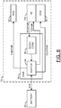
- the electronics apparatus 70 may include a fan (or pump) 92.
- the power switching circuit 90 generally comprises a block (or circuit) 94 and a block (or circuit) 96.
- the signal TEGPWR may be generated by the heat exchange unit 100 and presented to the circuit 96.
- the signal TCPWR may be exchanged between the heat exchange unit 100 and the circuit 94.
- a signal (e.g., FANPWR) may be generated by the circuit 94 and presented to the fan 92.
- a signal (e.g., ECUPWR) may be generated by the circuit 94 and transferred to the electronics control unit 80.
- the signal ECUPWR may provide electrical power to operate the circuitry inside the electronics control unit 80.
- a signal (e.g., SYS) may be exchanged between the battery 60 and the circuit 94.
- the signal SYS may carry a system voltage of the vehicle 50.
- the fan 72 may be operational to force air/cooling fluid in the stream INCOMING to the heat exchange unit 100. Control of the fan (e.g., on/off and speed) may be provided by the signal FANPWR generated by the power switching circuit 90. In some embodiments, the fan 72 may be eliminated where the cooling capacity of the heat exchange unit 100 is sufficient in the surrounding ambient air.
- the circuit 94 may implement a switch circuit.
- the switch circuit 94 is generally operational to switch electrical power among the battery 60, the electronic control unit 80, the fan 92 and the heat exchange unit 100.
- the switch circuit 94 may switch the signal TCPWR between sending power to the thermocouple 110 while in the heating mode and receiving power from the thermocouple 110 while in the cooling mode.
- the circuit 96 may implement a DC-to-DC converter circuit.
- the DC-to-DC converter circuit 96 may be operational to increase the voltage received from the thermoelectric generator units 108a-108n to a voltage compatible with the system voltage of the battery 60 (e.g., 12 to 15 volts) in the signal SYS.
- the output signal generated by the DC-to-DC converter circuit 96 may be provided to the switch circuit 94 for routing to the battery 60, the fan 92 and/or the electronic control unit 80.
- each unit cell of the thermoelectric generator units 108a-108n may generate tens of microvolts to hundreds of microvolts per degree of temperature difference, depending on the solid-state materials.
- each unit cell of the thermoelectric generator units 108a-108n may generate tens of microvolts to hundreds of microvolts per degree of temperature difference, depending on the solid-state materials.
- By connecting the unit cells in series within each thermoelectric generator unit 108a- 1 08n several tenths of a voltage may be created by each unit 108a-108n.
- some or all (as shown) of the thermoelectric generator units 108a-108n may be interconnected in series.
- the combined series voltage may be presented in the signal TEGPWR to the DC-to-DC converter circuit 96 or, if sufficiently high, to the switch circuit 94.
- thermoelectric generator units 108a-108n a block diagram of an example implementation of a parallel interconnect of the thermoelectric generator units 108a-108n is shown.
- the voltage generated by the individual thermoelectric generator units 108a-108n may be sufficient for use by the DC-to-DC converter and/or the switch circuit 94.
- the individual thermoelectric generator units 108a-108n may be interconnected in parallel to increase the total amount of current produced at the generated voltage.
- the resulting electrical power may be presented in the signal TEGPWR to the DC-to-DC converter circuit 96 and/or the switch circuit 94.
- FIGS. 1-8 may be designed, modeled, emulated, and/or simulated using one or more of a conventional general purpose processor, digital computer, microprocessor, microcontroller, distributed computer resources and/or similar computational machines, programmed according to the teachings of the present specification, as will be apparent to those skilled in the relevant art(s).
- Appropriate software, firmware, coding, routines, instructions, opcodes, microcode, and/or program modules may readily be prepared by skilled programmers based on the teachings of the present disclosure, as will also be apparent to those skilled in the relevant art(s).
- the software is generally embodied in a medium or several media, for example non-transitory storage media, and may be executed by one or more of the processors sequentially or in parallel.
- Embodiments of the present invention may also be implemented in one or more of ASICs (application specific integrated circuits), FPGAs (field programmable gate arrays), PLDs (programmable logic devices), CPLDs (complex programmable logic device), sea-of-gates, ASSPs (application specific standard products), SoCs (system-on-chips), MCM (multi-chip module), and integrated circuits.
- the circuitry may be implemented based on one or more hardware description languages.
- Embodiments of the present invention may be utilized in connection with flash memory, nonvolatile memory, random access memory, read-only memory, magnetic disks, floppy disks, optical disks such as DVDs and DVD RAM, magneto-optical disks and/or distributed storage systems.
Landscapes
- Engineering & Computer Science (AREA)
- Microelectronics & Electronic Packaging (AREA)
- Physics & Mathematics (AREA)
- Thermal Sciences (AREA)
- Cooling Or The Like Of Electrical Apparatus (AREA)
Claims (15)
- Vorrichtung, die Folgendes umfasst:eine Basis (102), die mit einem elektrischen Modul (84x), das im Betrieb Wärme erzeugt, thermisch koppelbar ist;eine oder mehrere erste Lamellen (104a-104n), die mit der Basis thermisch verbunden sind und mit dieser in einem direkten physischen Kontakt stehen;eine oder mehrere zweite Lamellen (106a-106n), die thermisch von der Basis isoliert sind; undeine oder mehrere thermoelektrische Erzeugungseinheiten (108a-108n), die (i) sowohl mit den ersten Lamellen als auch den zweiten Lamellen thermisch verbunden sind und in einem direkten physischen Kontakt mit diesen stehen und die (ii) ausgelegt sind, um eine Wärmedifferenz zwischen den ersten Lamellen und den zweiten Lamellen in ein elektrisches Signal (TEGPWR) an einem Anschluss umzuwandeln, um dadurch das elektrische Modul zu kühlen.
- Vorrichtung nach Anspruch 1, die ferner ein Thermoelement (110) umfasst, das (i) mit der Basis thermisch verbunden ist und (ii) ausgelegt ist, um ein zusätzliches elektrisches Signal (TCPWR) an einem zusätzlichen Anschluss als Reaktion auf die durch das elektrische Modul erzeugte Wärme zu erzeugen.
- Vorrichtung nach Anspruch 2, wobei das Thermoelement (110) ferner ausgelegt ist, um eine Erwärmungswärme zu erzeugen, um die elektrischen Module als Reaktion auf einen Strom, mit dem der zusätzliche Anschluss beaufschlagt wird, zu erwärmen.
- Vorrichtung nach einem der Ansprüche 1 bis 3, die ferner einen Isolator (112) umfasst, der ausgelegt ist, um die zweiten Lamellen an der Basis zu befestigen, wobei die thermoelektrischen Erzeugungseinheiten mit der Basis thermisch verbunden sind und in einem direkten physischen Kontakt mit dieser stehen.
- Vorrichtung nach einem der Ansprüche 1 bis 4, die ferner einen Verbinder (114) umfasst, der ausgelegt ist, um (i) mit jeder der thermoelektrischen Erzeugungseinheiten verbunden zu werden und (ii) das elektrische Signal an dem Anschluss bereitzustellen.
- Vorrichtung nach einem der Ansprüche 1 bis 5, wobei jede der thermoelektrischen Erzeugungseinheiten ausgelegt ist, um eine Spannung und einen Strom als Reaktion auf die Wärmedifferenz zwischen den ersten Lamellen und den zweiten Lamellen zu erzeugen.
- Vorrichtung nach Anspruch 6, wobei eine Vielzahl der thermoelektrischen Erzeugungseinheiten derart in Reihe geschaltet ist, dass das elektrische Signal an dem Anschluss eine höhere Spannung aufweist als die Spannung, die von jeder einzelnen der thermoelektrischen Erzeugungseinheiten erzeugt wird.
- Vorrichtung nach Anspruch 6, wobei eine Vielzahl der thermoelektrischen Erzeugungseinheiten so parallel geschaltet ist, dass das elektrische Signal an dem Anschluss einen höheren Strompegel aufweist als der Strom, der von jeder einzelnen der thermoelektrischen Erzeugungseinheiten erzeugt wird.
- Vorrichtung nach einem der Ansprüche 1 bis 8, wobei die ersten Lamellen ausgelegt sind, um zumindest 50 Watt Wärme abzuleiten.
- Vorrichtung nach einem der Ansprüche 1 bis 9, wobei die ersten Lamellen und die zweiten Lamellen normal zu einer Seite des elektrischen Moduls ausgerichtet sind, die mit der Basis verbunden ist.
- Vorrichtung nach einem der Ansprüche 1 bis 10, die ferner Folgendes umfasst:eine elektronische Steuereinheit (80), die eines oder mehrere der elektrischen Module umfasst, die während des Betriebs Wärme erzeugen;eine oder mehrere Wärmetauschereinheiten (100), die (i) jeweils die Basis, die eine oder die mehreren ersten Lamellen, die eine oder die mehreren zweiten Lamellen und die eine oder die mehreren thermoelektrischen Erzeugungseinheiten umfassen, die (ii) thermisch mit der elektronischen Steuereinheit verbunden und physisch direkt an diese gebondet sind und die (iii) ausgelegt sind, um (a) die elektrischen Module zu kühlen und (b) die Wärme an einem Anschluss in ein elektrisches Signal umzuwandeln, um dadurch die elektrischen Module weiter zu kühlen; undeinen Schalt-Schaltkreis (90), der ausgelegt ist, um das elektrische Signal, das durch die Wärmetauschereinheiten erzeugt wird, in eine Systemspannung einer Batterie (60), die in einem Motorfahrzeug (50) verwendet wird, umzuwandeln.
- Vorrichtung nach Anspruch 11, die ferner (A) einen Lüfter, der (i) durch den Schalt-Schaltkreis betrieben wird, umfasst und (ii) ausgelegt ist, um einströmende Luft auf die Wärmetauschereinheiten zu richten, wobei die eine oder die mehreren ersten Lamellen und die eine oder die mehreren zweiten Lamellen ferner ausgelegt sind, um erwärmte Luft durch Erwärmen der einströmenden Luft zu erzeugen, und (B) einen Kanal umfasst, der ausgelegt ist, um die erwärmte Luft in eine Fahrzeugkabine des Motorfahrzeugs zu leiten.
- Vorrichtung nach Anspruch 11, die ferner eine oder mehrere Kühlleitungen (72) umfasst, die ausgelegt sind, um Kühlfluid an die Wärmetauschereinheiten zu leiten, wobei das Kühlfluid Wärme von den Wärmetauschereinheiten abführt.
- Vorrichtung nach Anspruch 11, wobei die elektronische Steuereinheit eine autonome Ansteuerschaltung das Motorfahrzeugs umfasst.
- Vorrichtung nach Anspruch 11, wobei die ersten Lamellen und die zweiten Lamellen parallel zu einer Seite der elektronischen Steuereinheit ausgerichtet sind, die mit der Basis verbunden ist.
Applications Claiming Priority (2)
| Application Number | Priority Date | Filing Date | Title |
|---|---|---|---|
| US15/846,999 US10636725B2 (en) | 2017-12-19 | 2017-12-19 | Electrical module cooling through waste heat recovery |
| PCT/US2018/065955 WO2019126013A1 (en) | 2017-12-19 | 2018-12-17 | Electrical module cooling through waste heat recovery |
Publications (2)
| Publication Number | Publication Date |
|---|---|
| EP3729528A1 EP3729528A1 (de) | 2020-10-28 |
| EP3729528B1 true EP3729528B1 (de) | 2021-10-27 |
Family
ID=65013780
Family Applications (1)
| Application Number | Title | Priority Date | Filing Date |
|---|---|---|---|
| EP18833572.3A Active EP3729528B1 (de) | 2017-12-19 | 2018-12-17 | Kühlung eines elektrischen moduls durch abwärmerückgewinnung |
Country Status (4)
| Country | Link |
|---|---|
| US (1) | US10636725B2 (de) |
| EP (1) | EP3729528B1 (de) |
| CN (1) | CN111316456B (de) |
| WO (1) | WO2019126013A1 (de) |
Families Citing this family (3)
| Publication number | Priority date | Publication date | Assignee | Title |
|---|---|---|---|---|
| JP7746804B2 (ja) * | 2021-10-26 | 2025-10-01 | マツダ株式会社 | 演算ユニットの冷却構造 |
| US12401312B2 (en) * | 2023-03-23 | 2025-08-26 | Hamilton Sundstrand Corporation | Sensor-less temperature monitoring |
| CN116489963A (zh) * | 2023-05-11 | 2023-07-25 | 江苏科技大学 | 一种适用于高热流密度电子设备的冷却装置及冷却方法 |
Family Cites Families (38)
| Publication number | Priority date | Publication date | Assignee | Title |
|---|---|---|---|---|
| US8183456B1 (en) * | 2002-05-23 | 2012-05-22 | Jon Murray Schroeder | Thermoelectric device with make-before-break high frequency converter |
| US20050207115A1 (en) * | 2004-03-18 | 2005-09-22 | Hewlett-Packard Development Company, L.P. | Heat dissipating arrangement |
| KR100629679B1 (ko) | 2004-07-01 | 2006-09-29 | 삼성전자주식회사 | 열전 냉각 소자를 갖는 반도체 칩 패키지 |
| US7289331B2 (en) * | 2005-03-30 | 2007-10-30 | International Business Machines Corporation | Interposable heat sink for adjacent memory modules |
| CN2837523Y (zh) * | 2005-10-28 | 2006-11-15 | 刘万钊 | 发动机排气管余热发电装置 |
| US20070095379A1 (en) * | 2005-10-31 | 2007-05-03 | Taher Mahmoud A | Thermoelectric generator |
| US7480147B2 (en) * | 2006-10-13 | 2009-01-20 | Dell Products L.P. | Heat dissipation apparatus utilizing empty component slot |
| US7954332B2 (en) | 2007-01-19 | 2011-06-07 | Alkhorayef Petroleum Company | Temperature control systems and methods |
| US20080229759A1 (en) | 2007-03-21 | 2008-09-25 | Chien Ouyang | Method and apparatus for cooling integrated circuit chips using recycled power |
| DE102007029851A1 (de) * | 2007-06-28 | 2009-01-02 | Siemens Ag | Elektrisches Speichermodul |
| US8618406B1 (en) * | 2008-02-18 | 2013-12-31 | B & B Innovators, LLC | Thermoelectric power generation method and apparatus |
| US20090301541A1 (en) * | 2008-06-10 | 2009-12-10 | Watts Phillip C | Thermoelectric generator |
| US20100024859A1 (en) * | 2008-07-29 | 2010-02-04 | Bsst, Llc. | Thermoelectric power generator for variable thermal power source |
| DE102008049726B4 (de) | 2008-09-30 | 2012-02-09 | Advanced Micro Devices, Inc. | Gestapelte Chipkonfiguration mit stromgespeistem Wärmeübertragungssystem und Verfahren zum Steuern der Temperatur in einem Halbleiterbauelement |
| WO2010120287A1 (en) | 2009-04-15 | 2010-10-21 | Hewlett-Packard Development Company, L.P. | Generating and using electricity derived from waste heat of an electrical appliance |
| SI2320383T1 (sl) | 2009-10-20 | 2012-09-28 | Kapsch Trafficcom Ag | Naprava za vozilo |
| US8325478B2 (en) * | 2010-07-16 | 2012-12-04 | Rockwell Automation Technologies, Inc. | Cooling duct attachment and sealing for a motor drive |
| US8649179B2 (en) * | 2011-02-05 | 2014-02-11 | Laird Technologies, Inc. | Circuit assemblies including thermoelectric modules |
| US20120204577A1 (en) * | 2011-02-16 | 2012-08-16 | Ludwig Lester F | Flexible modular hierarchical adaptively controlled electronic-system cooling and energy harvesting for IC chip packaging, printed circuit boards, subsystems, cages, racks, IT rooms, and data centers using quantum and classical thermoelectric materials |
| US20140202178A1 (en) * | 2011-06-30 | 2014-07-24 | Michael W. Trumbower | Multiple circuit cooling system |
| DE112013000620T5 (de) * | 2012-01-20 | 2014-10-16 | Gentherm Incorporated | Integrierter Katalysator/Thermoelektrischer Generator |
| US8997502B2 (en) * | 2012-03-01 | 2015-04-07 | Marlow Industries, Inc. | Thermoelectric assembly for improved airflow |
| US8766656B2 (en) * | 2012-04-18 | 2014-07-01 | Silicon Turnkey Solutions Inc. | Systems and methods for thermal control |
| US10584884B2 (en) * | 2013-03-15 | 2020-03-10 | Nortek Air Solutions Canada, Inc. | Control system and method for a liquid desiccant air delivery system |
| US9459668B2 (en) * | 2013-05-16 | 2016-10-04 | Amazon Technologies, Inc. | Cooling system with desiccant dehumidification |
| US9218028B2 (en) * | 2013-06-07 | 2015-12-22 | Apple Inc. | Computer housing |
| KR101558661B1 (ko) * | 2013-10-10 | 2015-10-07 | 현대자동차주식회사 | 차량의 고전압배터리 공조시스템 및 공조방법 |
| JP2015186989A (ja) * | 2014-03-12 | 2015-10-29 | カルソニックカンセイ株式会社 | 車載温調装置、車両用空調装置及びバッテリ温調装置 |
| GB2591198B (en) * | 2014-04-04 | 2021-10-27 | It Is Int Ltd | Biochemical reaction system |
| WO2016025985A1 (en) | 2014-08-20 | 2016-02-25 | Vand Technology Pty Ltd | Method and system of rapid heating and cooling of a fluid |
| US20160165752A1 (en) * | 2014-11-04 | 2016-06-09 | Ge Aviation Systems Llc | Heat exchanger assembly |
| US10088178B2 (en) * | 2015-05-05 | 2018-10-02 | MJC, Inc. | Multi-zone variable refrigerant flow heating/cooling unit |
| EP3113591B1 (de) * | 2015-06-29 | 2018-04-18 | Vertiv S.R.L. | Klimaanlage mit freier kühlung sowie verfahren zum betrieb solch einer klimaanlage |
| US10411619B2 (en) * | 2015-08-28 | 2019-09-10 | Regal Beloit America, Inc. | Motor controller, drive circuit, and methods for combined electric motor control |
| US20170081040A1 (en) * | 2015-09-21 | 2017-03-23 | Hamilton Sundstrand Corporation | Heat exchanger and cooling system for generator electronics cooling |
| EP3386285B1 (de) * | 2015-12-02 | 2021-07-07 | Nec Network And Sensor Systems, Ltd. | Elektronikkomponentengehäusevorrichtung und elektronische vorrichtung |
| JP6929788B2 (ja) * | 2015-12-04 | 2021-09-01 | ローム株式会社 | パワーモジュール装置、および電気自動車またはハイブリッドカー |
| US10251234B2 (en) * | 2016-06-24 | 2019-04-02 | David Hirshberg | Thermoelectric thermal management system |
-
2017
- 2017-12-19 US US15/846,999 patent/US10636725B2/en active Active
-
2018
- 2018-12-17 EP EP18833572.3A patent/EP3729528B1/de active Active
- 2018-12-17 CN CN201880071901.6A patent/CN111316456B/zh active Active
- 2018-12-17 WO PCT/US2018/065955 patent/WO2019126013A1/en not_active Ceased
Also Published As
| Publication number | Publication date |
|---|---|
| CN111316456B (zh) | 2023-11-14 |
| US10636725B2 (en) | 2020-04-28 |
| WO2019126013A1 (en) | 2019-06-27 |
| CN111316456A (zh) | 2020-06-19 |
| EP3729528A1 (de) | 2020-10-28 |
| US20190189535A1 (en) | 2019-06-20 |
Similar Documents
| Publication | Publication Date | Title |
|---|---|---|
| US10784546B2 (en) | Thermoelectric-based thermal management system | |
| CN109109608B (zh) | 用于向自主车辆的车厢提供加热和冷却的系统和方法 | |
| US10377264B2 (en) | Vehicle conductive charge port having cooling infrastructure | |
| CN102596603B (zh) | 热交换器装置 | |
| CN106717139B (zh) | 石墨热电和/或电阻热管理系统和方法 | |
| US7246496B2 (en) | Thermoelectric based heating and cooling system for a hybrid-electric vehicle | |
| EP3729528B1 (de) | Kühlung eines elektrischen moduls durch abwärmerückgewinnung | |
| US20120222441A1 (en) | Heat Cycle System for Mobile Object | |
| US20200313260A1 (en) | Cooling plate for a rechargeable energy storage system | |
| CN104779423A (zh) | 用于电气化车辆的电池热管理系统 | |
| CN104756308A (zh) | 电池系统和机动车 | |
| CN105470604A (zh) | 车载用电池 | |
| CN111845250A (zh) | 车辆的空调装置 | |
| CN110383574A (zh) | 充电装置和车载电源装置 | |
| CN104564298A (zh) | 用于电动车的冷却系统以及用于制造冷却系统的方法 | |
| JP2020103031A (ja) | 電気的バスバーおよび冷却モジュールの電気アセンブリ | |
| CN107859553A (zh) | 包括热电发电机的车辆 | |
| CN115087554A (zh) | 一种利用自控冷却的驱动装置 | |
| CN111092558A (zh) | 逆变器设备和带有这样的逆变器设备的机动车 | |
| US20080271462A1 (en) | Thermal electric hvac module | |
| CN118235282A (zh) | 热管理系统、电机控制方法及车辆 | |
| KR20140111056A (ko) | 열전소자를 이용한 인버터 냉각 장치 | |
| RU97108440A (ru) | Термоэлектрическое устройство для создания микроклимата в автомобиле |
Legal Events
| Date | Code | Title | Description |
|---|---|---|---|
| STAA | Information on the status of an ep patent application or granted ep patent |
Free format text: STATUS: UNKNOWN |
|
| STAA | Information on the status of an ep patent application or granted ep patent |
Free format text: STATUS: THE INTERNATIONAL PUBLICATION HAS BEEN MADE |
|
| PUAI | Public reference made under article 153(3) epc to a published international application that has entered the european phase |
Free format text: ORIGINAL CODE: 0009012 |
|
| STAA | Information on the status of an ep patent application or granted ep patent |
Free format text: STATUS: REQUEST FOR EXAMINATION WAS MADE |
|
| 17P | Request for examination filed |
Effective date: 20200422 |
|
| AK | Designated contracting states |
Kind code of ref document: A1 Designated state(s): AL AT BE BG CH CY CZ DE DK EE ES FI FR GB GR HR HU IE IS IT LI LT LU LV MC MK MT NL NO PL PT RO RS SE SI SK SM TR |
|
| AX | Request for extension of the european patent |
Extension state: BA ME |
|
| DAV | Request for validation of the european patent (deleted) | ||
| DAX | Request for extension of the european patent (deleted) | ||
| GRAP | Despatch of communication of intention to grant a patent |
Free format text: ORIGINAL CODE: EPIDOSNIGR1 |
|
| STAA | Information on the status of an ep patent application or granted ep patent |
Free format text: STATUS: GRANT OF PATENT IS INTENDED |
|
| INTG | Intention to grant announced |
Effective date: 20210623 |
|
| GRAS | Grant fee paid |
Free format text: ORIGINAL CODE: EPIDOSNIGR3 |
|
| GRAA | (expected) grant |
Free format text: ORIGINAL CODE: 0009210 |
|
| STAA | Information on the status of an ep patent application or granted ep patent |
Free format text: STATUS: THE PATENT HAS BEEN GRANTED |
|
| AK | Designated contracting states |
Kind code of ref document: B1 Designated state(s): AL AT BE BG CH CY CZ DE DK EE ES FI FR GB GR HR HU IE IS IT LI LT LU LV MC MK MT NL NO PL PT RO RS SE SI SK SM TR |
|
| REG | Reference to a national code |
Ref country code: GB Ref legal event code: FG4D |
|
| REG | Reference to a national code |
Ref country code: CH Ref legal event code: EP |
|
| REG | Reference to a national code |
Ref country code: AT Ref legal event code: REF Ref document number: 1442630 Country of ref document: AT Kind code of ref document: T Effective date: 20211115 |
|
| REG | Reference to a national code |
Ref country code: DE Ref legal event code: R096 Ref document number: 602018025861 Country of ref document: DE |
|
| REG | Reference to a national code |
Ref country code: IE Ref legal event code: FG4D |
|
| REG | Reference to a national code |
Ref country code: LT Ref legal event code: MG9D |
|
| REG | Reference to a national code |
Ref country code: NL Ref legal event code: MP Effective date: 20211027 |
|
| REG | Reference to a national code |
Ref country code: AT Ref legal event code: MK05 Ref document number: 1442630 Country of ref document: AT Kind code of ref document: T Effective date: 20211027 |
|
| PG25 | Lapsed in a contracting state [announced via postgrant information from national office to epo] |
Ref country code: RS Free format text: LAPSE BECAUSE OF FAILURE TO SUBMIT A TRANSLATION OF THE DESCRIPTION OR TO PAY THE FEE WITHIN THE PRESCRIBED TIME-LIMIT Effective date: 20211027 Ref country code: LT Free format text: LAPSE BECAUSE OF FAILURE TO SUBMIT A TRANSLATION OF THE DESCRIPTION OR TO PAY THE FEE WITHIN THE PRESCRIBED TIME-LIMIT Effective date: 20211027 Ref country code: FI Free format text: LAPSE BECAUSE OF FAILURE TO SUBMIT A TRANSLATION OF THE DESCRIPTION OR TO PAY THE FEE WITHIN THE PRESCRIBED TIME-LIMIT Effective date: 20211027 Ref country code: BG Free format text: LAPSE BECAUSE OF FAILURE TO SUBMIT A TRANSLATION OF THE DESCRIPTION OR TO PAY THE FEE WITHIN THE PRESCRIBED TIME-LIMIT Effective date: 20220127 Ref country code: AT Free format text: LAPSE BECAUSE OF FAILURE TO SUBMIT A TRANSLATION OF THE DESCRIPTION OR TO PAY THE FEE WITHIN THE PRESCRIBED TIME-LIMIT Effective date: 20211027 |
|
| PG25 | Lapsed in a contracting state [announced via postgrant information from national office to epo] |
Ref country code: IS Free format text: LAPSE BECAUSE OF FAILURE TO SUBMIT A TRANSLATION OF THE DESCRIPTION OR TO PAY THE FEE WITHIN THE PRESCRIBED TIME-LIMIT Effective date: 20220227 Ref country code: SE Free format text: LAPSE BECAUSE OF FAILURE TO SUBMIT A TRANSLATION OF THE DESCRIPTION OR TO PAY THE FEE WITHIN THE PRESCRIBED TIME-LIMIT Effective date: 20211027 Ref country code: PT Free format text: LAPSE BECAUSE OF FAILURE TO SUBMIT A TRANSLATION OF THE DESCRIPTION OR TO PAY THE FEE WITHIN THE PRESCRIBED TIME-LIMIT Effective date: 20220228 Ref country code: PL Free format text: LAPSE BECAUSE OF FAILURE TO SUBMIT A TRANSLATION OF THE DESCRIPTION OR TO PAY THE FEE WITHIN THE PRESCRIBED TIME-LIMIT Effective date: 20211027 Ref country code: NO Free format text: LAPSE BECAUSE OF FAILURE TO SUBMIT A TRANSLATION OF THE DESCRIPTION OR TO PAY THE FEE WITHIN THE PRESCRIBED TIME-LIMIT Effective date: 20220127 Ref country code: NL Free format text: LAPSE BECAUSE OF FAILURE TO SUBMIT A TRANSLATION OF THE DESCRIPTION OR TO PAY THE FEE WITHIN THE PRESCRIBED TIME-LIMIT Effective date: 20211027 Ref country code: LV Free format text: LAPSE BECAUSE OF FAILURE TO SUBMIT A TRANSLATION OF THE DESCRIPTION OR TO PAY THE FEE WITHIN THE PRESCRIBED TIME-LIMIT Effective date: 20211027 Ref country code: HR Free format text: LAPSE BECAUSE OF FAILURE TO SUBMIT A TRANSLATION OF THE DESCRIPTION OR TO PAY THE FEE WITHIN THE PRESCRIBED TIME-LIMIT Effective date: 20211027 Ref country code: GR Free format text: LAPSE BECAUSE OF FAILURE TO SUBMIT A TRANSLATION OF THE DESCRIPTION OR TO PAY THE FEE WITHIN THE PRESCRIBED TIME-LIMIT Effective date: 20220128 Ref country code: ES Free format text: LAPSE BECAUSE OF FAILURE TO SUBMIT A TRANSLATION OF THE DESCRIPTION OR TO PAY THE FEE WITHIN THE PRESCRIBED TIME-LIMIT Effective date: 20211027 |
|
| REG | Reference to a national code |
Ref country code: DE Ref legal event code: R097 Ref document number: 602018025861 Country of ref document: DE |
|
| PG25 | Lapsed in a contracting state [announced via postgrant information from national office to epo] |
Ref country code: SM Free format text: LAPSE BECAUSE OF FAILURE TO SUBMIT A TRANSLATION OF THE DESCRIPTION OR TO PAY THE FEE WITHIN THE PRESCRIBED TIME-LIMIT Effective date: 20211027 Ref country code: SK Free format text: LAPSE BECAUSE OF FAILURE TO SUBMIT A TRANSLATION OF THE DESCRIPTION OR TO PAY THE FEE WITHIN THE PRESCRIBED TIME-LIMIT Effective date: 20211027 Ref country code: RO Free format text: LAPSE BECAUSE OF FAILURE TO SUBMIT A TRANSLATION OF THE DESCRIPTION OR TO PAY THE FEE WITHIN THE PRESCRIBED TIME-LIMIT Effective date: 20211027 Ref country code: MC Free format text: LAPSE BECAUSE OF FAILURE TO SUBMIT A TRANSLATION OF THE DESCRIPTION OR TO PAY THE FEE WITHIN THE PRESCRIBED TIME-LIMIT Effective date: 20211027 Ref country code: EE Free format text: LAPSE BECAUSE OF FAILURE TO SUBMIT A TRANSLATION OF THE DESCRIPTION OR TO PAY THE FEE WITHIN THE PRESCRIBED TIME-LIMIT Effective date: 20211027 Ref country code: DK Free format text: LAPSE BECAUSE OF FAILURE TO SUBMIT A TRANSLATION OF THE DESCRIPTION OR TO PAY THE FEE WITHIN THE PRESCRIBED TIME-LIMIT Effective date: 20211027 Ref country code: CZ Free format text: LAPSE BECAUSE OF FAILURE TO SUBMIT A TRANSLATION OF THE DESCRIPTION OR TO PAY THE FEE WITHIN THE PRESCRIBED TIME-LIMIT Effective date: 20211027 |
|
| REG | Reference to a national code |
Ref country code: CH Ref legal event code: PL |
|
| PLBE | No opposition filed within time limit |
Free format text: ORIGINAL CODE: 0009261 |
|
| STAA | Information on the status of an ep patent application or granted ep patent |
Free format text: STATUS: NO OPPOSITION FILED WITHIN TIME LIMIT |
|
| REG | Reference to a national code |
Ref country code: BE Ref legal event code: MM Effective date: 20211231 |
|
| 26N | No opposition filed |
Effective date: 20220728 |
|
| PG25 | Lapsed in a contracting state [announced via postgrant information from national office to epo] |
Ref country code: LU Free format text: LAPSE BECAUSE OF NON-PAYMENT OF DUE FEES Effective date: 20211217 Ref country code: IE Free format text: LAPSE BECAUSE OF NON-PAYMENT OF DUE FEES Effective date: 20211217 Ref country code: AL Free format text: LAPSE BECAUSE OF FAILURE TO SUBMIT A TRANSLATION OF THE DESCRIPTION OR TO PAY THE FEE WITHIN THE PRESCRIBED TIME-LIMIT Effective date: 20211027 |
|
| REG | Reference to a national code |
Ref country code: DE Ref legal event code: R079 Ref document number: 602018025861 Country of ref document: DE Free format text: PREVIOUS MAIN CLASS: H01L0035300000 Ipc: H10N0010130000 |
|
| PG25 | Lapsed in a contracting state [announced via postgrant information from national office to epo] |
Ref country code: SI Free format text: LAPSE BECAUSE OF FAILURE TO SUBMIT A TRANSLATION OF THE DESCRIPTION OR TO PAY THE FEE WITHIN THE PRESCRIBED TIME-LIMIT Effective date: 20211027 Ref country code: FR Free format text: LAPSE BECAUSE OF NON-PAYMENT OF DUE FEES Effective date: 20211227 Ref country code: BE Free format text: LAPSE BECAUSE OF NON-PAYMENT OF DUE FEES Effective date: 20211231 |
|
| PG25 | Lapsed in a contracting state [announced via postgrant information from national office to epo] |
Ref country code: LI Free format text: LAPSE BECAUSE OF NON-PAYMENT OF DUE FEES Effective date: 20211231 Ref country code: CH Free format text: LAPSE BECAUSE OF NON-PAYMENT OF DUE FEES Effective date: 20211231 |
|
| REG | Reference to a national code |
Ref country code: DE Ref legal event code: R081 Ref document number: 602018025861 Country of ref document: DE Owner name: VEONEER US, LLC (N.D.GES.D. STAATES DELAWARE),, US Free format text: FORMER OWNER: VEONEER US, INC., SOUTHFIELD, MICH., US Ref country code: DE Ref legal event code: R081 Ref document number: 602018025861 Country of ref document: DE Owner name: MAGNA ELECTRONICS, LLC (N.D.GES.D. STAATES DEL, US Free format text: FORMER OWNER: VEONEER US, INC., SOUTHFIELD, MICH., US |
|
| PG25 | Lapsed in a contracting state [announced via postgrant information from national office to epo] |
Ref country code: IT Free format text: LAPSE BECAUSE OF FAILURE TO SUBMIT A TRANSLATION OF THE DESCRIPTION OR TO PAY THE FEE WITHIN THE PRESCRIBED TIME-LIMIT Effective date: 20211027 |
|
| PG25 | Lapsed in a contracting state [announced via postgrant information from national office to epo] |
Ref country code: CY Free format text: LAPSE BECAUSE OF FAILURE TO SUBMIT A TRANSLATION OF THE DESCRIPTION OR TO PAY THE FEE WITHIN THE PRESCRIBED TIME-LIMIT Effective date: 20211027 |
|
| PG25 | Lapsed in a contracting state [announced via postgrant information from national office to epo] |
Ref country code: HU Free format text: LAPSE BECAUSE OF FAILURE TO SUBMIT A TRANSLATION OF THE DESCRIPTION OR TO PAY THE FEE WITHIN THE PRESCRIBED TIME-LIMIT; INVALID AB INITIO Effective date: 20181217 |
|
| GBPC | Gb: european patent ceased through non-payment of renewal fee |
Effective date: 20221217 |
|
| PG25 | Lapsed in a contracting state [announced via postgrant information from national office to epo] |
Ref country code: GB Free format text: LAPSE BECAUSE OF NON-PAYMENT OF DUE FEES Effective date: 20221217 |
|
| REG | Reference to a national code |
Ref country code: DE Ref legal event code: R081 Ref document number: 602018025861 Country of ref document: DE Owner name: MAGNA ELECTRONICS, LLC (N.D.GES.D. STAATES DEL, US Free format text: FORMER OWNER: VEONEER US, LLC (N.D.GES.D. STAATES DELAWARE), SOUTHFIELD, MI, US |
|
| PG25 | Lapsed in a contracting state [announced via postgrant information from national office to epo] |
Ref country code: MK Free format text: LAPSE BECAUSE OF FAILURE TO SUBMIT A TRANSLATION OF THE DESCRIPTION OR TO PAY THE FEE WITHIN THE PRESCRIBED TIME-LIMIT Effective date: 20211027 |
|
| PG25 | Lapsed in a contracting state [announced via postgrant information from national office to epo] |
Ref country code: MT Free format text: LAPSE BECAUSE OF FAILURE TO SUBMIT A TRANSLATION OF THE DESCRIPTION OR TO PAY THE FEE WITHIN THE PRESCRIBED TIME-LIMIT Effective date: 20211027 |
|
| PG25 | Lapsed in a contracting state [announced via postgrant information from national office to epo] |
Ref country code: TR Free format text: LAPSE BECAUSE OF FAILURE TO SUBMIT A TRANSLATION OF THE DESCRIPTION OR TO PAY THE FEE WITHIN THE PRESCRIBED TIME-LIMIT Effective date: 20211027 |
|
| PGFP | Annual fee paid to national office [announced via postgrant information from national office to epo] |
Ref country code: DE Payment date: 20251222 Year of fee payment: 8 |