EP3729548B1 - Interconnecteur à état de surface dégradé pour la tenue des étanchéités - Google Patents
Interconnecteur à état de surface dégradé pour la tenue des étanchéités Download PDFInfo
- Publication number
- EP3729548B1 EP3729548B1 EP18842427.9A EP18842427A EP3729548B1 EP 3729548 B1 EP3729548 B1 EP 3729548B1 EP 18842427 A EP18842427 A EP 18842427A EP 3729548 B1 EP3729548 B1 EP 3729548B1
- Authority
- EP
- European Patent Office
- Prior art keywords
- face
- interconnector
- rough region
- insulating
- bonding material
- Prior art date
- Legal status (The legal status is an assumption and is not a legal conclusion. Google has not performed a legal analysis and makes no representation as to the accuracy of the status listed.)
- Active
Links
Images


Classifications
-
- H—ELECTRICITY
- H01—ELECTRIC ELEMENTS
- H01M—PROCESSES OR MEANS, e.g. BATTERIES, FOR THE DIRECT CONVERSION OF CHEMICAL ENERGY INTO ELECTRICAL ENERGY
- H01M8/00—Fuel cells; Manufacture thereof
- H01M8/02—Details
- H01M8/0202—Collectors; Separators, e.g. bipolar separators; Interconnectors
- H01M8/0204—Non-porous and characterised by the material
- H01M8/0206—Metals or alloys
-
- H—ELECTRICITY
- H01—ELECTRIC ELEMENTS
- H01M—PROCESSES OR MEANS, e.g. BATTERIES, FOR THE DIRECT CONVERSION OF CHEMICAL ENERGY INTO ELECTRICAL ENERGY
- H01M8/00—Fuel cells; Manufacture thereof
- H01M8/02—Details
- H01M8/0202—Collectors; Separators, e.g. bipolar separators; Interconnectors
-
- H—ELECTRICITY
- H01—ELECTRIC ELEMENTS
- H01M—PROCESSES OR MEANS, e.g. BATTERIES, FOR THE DIRECT CONVERSION OF CHEMICAL ENERGY INTO ELECTRICAL ENERGY
- H01M8/00—Fuel cells; Manufacture thereof
- H01M8/02—Details
- H01M8/0271—Sealing or supporting means around electrodes, matrices or membranes
-
- H—ELECTRICITY
- H01—ELECTRIC ELEMENTS
- H01M—PROCESSES OR MEANS, e.g. BATTERIES, FOR THE DIRECT CONVERSION OF CHEMICAL ENERGY INTO ELECTRICAL ENERGY
- H01M8/00—Fuel cells; Manufacture thereof
- H01M8/02—Details
- H01M8/0271—Sealing or supporting means around electrodes, matrices or membranes
- H01M8/0273—Sealing or supporting means around electrodes, matrices or membranes with sealing or supporting means in the form of a frame
-
- H—ELECTRICITY
- H01—ELECTRIC ELEMENTS
- H01M—PROCESSES OR MEANS, e.g. BATTERIES, FOR THE DIRECT CONVERSION OF CHEMICAL ENERGY INTO ELECTRICAL ENERGY
- H01M8/00—Fuel cells; Manufacture thereof
- H01M8/02—Details
- H01M8/0271—Sealing or supporting means around electrodes, matrices or membranes
- H01M8/0276—Sealing means characterised by their form
-
- H—ELECTRICITY
- H01—ELECTRIC ELEMENTS
- H01M—PROCESSES OR MEANS, e.g. BATTERIES, FOR THE DIRECT CONVERSION OF CHEMICAL ENERGY INTO ELECTRICAL ENERGY
- H01M8/00—Fuel cells; Manufacture thereof
- H01M8/02—Details
- H01M8/0271—Sealing or supporting means around electrodes, matrices or membranes
- H01M8/0276—Sealing means characterised by their form
- H01M8/0278—O-rings
-
- H—ELECTRICITY
- H01—ELECTRIC ELEMENTS
- H01M—PROCESSES OR MEANS, e.g. BATTERIES, FOR THE DIRECT CONVERSION OF CHEMICAL ENERGY INTO ELECTRICAL ENERGY
- H01M8/00—Fuel cells; Manufacture thereof
- H01M8/02—Details
- H01M8/0271—Sealing or supporting means around electrodes, matrices or membranes
- H01M8/028—Sealing means characterised by their material
-
- H—ELECTRICITY
- H01—ELECTRIC ELEMENTS
- H01M—PROCESSES OR MEANS, e.g. BATTERIES, FOR THE DIRECT CONVERSION OF CHEMICAL ENERGY INTO ELECTRICAL ENERGY
- H01M8/00—Fuel cells; Manufacture thereof
- H01M8/02—Details
- H01M8/0271—Sealing or supporting means around electrodes, matrices or membranes
- H01M8/028—Sealing means characterised by their material
- H01M8/0282—Inorganic material
-
- H—ELECTRICITY
- H01—ELECTRIC ELEMENTS
- H01M—PROCESSES OR MEANS, e.g. BATTERIES, FOR THE DIRECT CONVERSION OF CHEMICAL ENERGY INTO ELECTRICAL ENERGY
- H01M8/00—Fuel cells; Manufacture thereof
- H01M8/02—Details
- H01M8/0271—Sealing or supporting means around electrodes, matrices or membranes
- H01M8/028—Sealing means characterised by their material
- H01M8/0284—Organic resins; Organic polymers
-
- H—ELECTRICITY
- H01—ELECTRIC ELEMENTS
- H01M—PROCESSES OR MEANS, e.g. BATTERIES, FOR THE DIRECT CONVERSION OF CHEMICAL ENERGY INTO ELECTRICAL ENERGY
- H01M8/00—Fuel cells; Manufacture thereof
- H01M8/10—Fuel cells with solid electrolytes
- H01M8/12—Fuel cells with solid electrolytes operating at high temperature, e.g. with stabilised ZrO2 electrolyte
- H01M2008/1293—Fuel cells with solid oxide electrolytes
-
- Y—GENERAL TAGGING OF NEW TECHNOLOGICAL DEVELOPMENTS; GENERAL TAGGING OF CROSS-SECTIONAL TECHNOLOGIES SPANNING OVER SEVERAL SECTIONS OF THE IPC; TECHNICAL SUBJECTS COVERED BY FORMER USPC CROSS-REFERENCE ART COLLECTIONS [XRACs] AND DIGESTS
- Y02—TECHNOLOGIES OR APPLICATIONS FOR MITIGATION OR ADAPTATION AGAINST CLIMATE CHANGE
- Y02E—REDUCTION OF GREENHOUSE GAS [GHG] EMISSIONS, RELATED TO ENERGY GENERATION, TRANSMISSION OR DISTRIBUTION
- Y02E60/00—Enabling technologies; Technologies with a potential or indirect contribution to GHG emissions mitigation
- Y02E60/30—Hydrogen technology
- Y02E60/36—Hydrogen production from non-carbon containing sources, e.g. by water electrolysis
-
- Y—GENERAL TAGGING OF NEW TECHNOLOGICAL DEVELOPMENTS; GENERAL TAGGING OF CROSS-SECTIONAL TECHNOLOGIES SPANNING OVER SEVERAL SECTIONS OF THE IPC; TECHNICAL SUBJECTS COVERED BY FORMER USPC CROSS-REFERENCE ART COLLECTIONS [XRACs] AND DIGESTS
- Y02—TECHNOLOGIES OR APPLICATIONS FOR MITIGATION OR ADAPTATION AGAINST CLIMATE CHANGE
- Y02E—REDUCTION OF GREENHOUSE GAS [GHG] EMISSIONS, RELATED TO ENERGY GENERATION, TRANSMISSION OR DISTRIBUTION
- Y02E60/00—Enabling technologies; Technologies with a potential or indirect contribution to GHG emissions mitigation
- Y02E60/30—Hydrogen technology
- Y02E60/50—Fuel cells
Definitions
- the present application relates to the field of electrochemical devices and more precisely to the implementation of improved sealing structures in such devices.
- SOFC Solid Oxide Fuel Cell
- EHT high temperature water vapor
- EVHT high temperature water vapor electrolysis
- HTE high temperature water vapor
- HTSE High Temperature Steam Electrolysis
- SOEC solid Oxide Electrolyte Cell
- electrochemical devices comprise a stack (“stack” according to the English terminology) of elementary modules, also called “electrochemical cells”, placed in series.
- Each elementary module can be, as illustrated in the figure 1 , formed of an assembly 4 of an electrolyte 1 with two electrodes: an anode 2 and a cathode 3.
- the assembly 4 is generally clamped between two interconnection plates 5.1, 5.2 also called “interconnectors”.
- a complete electrolyser is thus formed from a stack comprising an alternation of cells and interconnectors.
- the interconnectors 5.1, 5.2 are electrically conductive.
- One function of the interconnectors 5.1, 5.2 is therefore to supply an electrochemical cell with electric current.
- the interconnectors typically comprise a first face in contact with the cathode of one cell and a main face, opposite the first face, in contact with the anode of another cell.
- the interconnectors 5.1, 5.2 can also participate in the distribution and / or recovery of gas produced while separating the anode and cathode compartments of two adjacent cells.
- the documents FR2988916A1 , FR3014246A1 , and FR3000108 give various examples of insulating gaskets ensuring the seal in an electrochemical device of the SOEC or SOFC type, the seal typically comprising a connecting material such as glass intended to form an insulating watertight partition and placed in a reception support insulation brought into contact with an interconnector.
- the insulating support is generally formed of a mica frame.
- leaks can appear at these insulation joints, which can make the adjoining electrochemical cell defective.
- an embodiment of the present invention provides a structure for an electrochemical device, in particular of the solid oxide fuel cell (SOFC) type or of the solid oxide high temperature water vapor electrolyser (SOEC) type.
- the structure comprising at least one conductive interconnector support element characterized by at least a first face having at least one localized rough region, said rough region being able to be brought into contact with an insulating bonding material of a gasket. sealing.
- the conductive support element may, for example, be in the form of a metal plate, or sheet, or of several assembled metal sheets or plates.
- the interconnector may for its part be formed of a support element or of several assembled conductive support elements.
- the interconnector may itself be formed of a plate or a sheet, or even of several plates, or of several stacked sheets.
- the insulating bonding material affixed to the rough region is typically glass-based or glass-ceramic.
- the structure may further comprise an insulating support which supports or receives the insulating bonding material, in particular based on glass or glass-ceramic.
- the insulating support can be provided with a central opening adapted to accommodate at least one electrochemical cell.
- the insulating connecting material may be in the form of at least one bead in contact with said rough region and distributed around said central opening.
- the insulating support comprises one or more peripheral openings arranged around the central opening, one or more other cords of insulating connecting material are distributed respectively around said one or more peripheral openings.
- the rough region has an arrangement on the first face according to at least one given pattern forming one or more closed contours, the cord or beads in contact with said rough region being arranged in a pattern reproducing said given pattern.
- the conductive support member has at least a second face opposite the first face and which may also have at least one other localized rough region.
- this other localized rough region can be brought into contact with another seal.
- This other seal may be arranged between said interconnector and another interconnector.
- the other seal may be in contact with a rough region formed on one face of this other interconnector.
- said conductive support element may be placed against a main face of an electrically insulating support, while another interconnector is placed against another main face of this electrically insulating support opposite to said main face.
- the insulating support may advantageously be provided with at least one through slot filled with said insulating bonding material of the seal, the through slot extending between said main face and said other main face, so that the insulating bonding material disposed in said lumen passes through the electrically insulating support and is disposed in contact with a rough region of this other interconnector.
- the seal is mounted in contact with metal surfaces or support elements on a smooth metal surface.
- Step a) is advantageously carried out by projecting balls or particles or grains, through at least one hole of a protective mask placed opposite said first face of said conductive support element, the hole being arranged next to the given region. A localized treatment is thus carried out while protecting other areas of the conductive support element.
- the conductive support element may be in the form of a first metal sheet (or plate), the method further comprising, after step a), the assembly of this first sheet (or metal plate) with one or more other metal sheets (or plates) to form an interconnector.
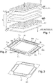
- interconnector support element 50 An example of the interconnector support element 50 is illustrated in figure 2 .
- the interconnector is intended to be integrated into an electrochemical device, in particular of the electrolyser type such as for example a high temperature water vapor electrolyser with solid oxide (SOEC) or else of the fuel cell type such as for example a solid oxide fuel cell (SOFC).
- the electrolyser type such as for example a high temperature water vapor electrolyser with solid oxide (SOEC) or else of the fuel cell type such as for example a solid oxide fuel cell (SOFC).
- SOEC high temperature water vapor electrolyser with solid oxide
- SOFC solid oxide fuel cell
- the interconnector can thus fulfill the same functions as that of the interconnectors 5.1, 5.2 described previously in connection with the figure 1 .
- the support element 50 is based on an electrically conductive material, and may be in the form of a sheet or an assembly of several sheets.
- the material of the support member 50 is typically metallic and preferably able to resist corrosion and high temperatures.
- a ferric stainless steel is used, such as a steel of grade K41X (designated according to the standard EP 10088-2 by: X2CrTiNb18 1.4509, or according to the US standard by: 43932, Type 441), or for example nickel-based steels such as a steel of the Inconel 600 type, registered trademark of the company Special Metals Corporation.
- the support element 50 implemented according to the invention comprises a face 50A provided with a localized rough region 52.
- the rough region 52 has in particular an arithmetic mean roughness parameter Ra corresponding to the arithmetic mean roughness of its profile which is greater than the rest of the face 51 or at least other areas 53 of the face 51 located around the rough region 52.
- the roughness of the region is a signature of a type of machining.
- the roughness can take on the appearance of streaks or furrows.
- the rough region 52 has a Ra parameter of 3.2 to 50 ⁇ m (micrometers) or belongs to a roughness class between N8 and N12 if we consider the old afnor NF E 05-051 standard.
- the other zones 53 of the first face 50A around the localized rough region 52 have a lower average roughness than that of the rough region 52. If we consider for example a support 50 of cold rolled steel of thickness 1. of the order of 0.2 mm, the other zones 53 have an average roughness of between 0.2 and 0.5 ⁇ m (micrometers).
- the rough region 52 is arranged on the support element 50 as a function of the arrangement of a seal and more particularly of that of an insulating material (not shown in this figure) called “connecting”, therefore. seal.
- This connecting material is typically based on glass or glass-ceramic and designed to accommodate the thermal expansions of different elements, in particular metal support elements connected by this seal and which belong to different interconnectors.
- the rough region 52 on the support element 50 forms a first pattern producing a closed contour C1 disposed in a peripheral zone of the support element 50.
- the rough region 52 can also include other patterns arranged around the first pattern and also forming other closed contours C11, C12, C13, C14. These other patterns have in this particular example a part in common with the first pattern and are respectively arranged around openings 55a, 55b, 55c, 55d provided in the support element 50.
- the rough region 52 results from a localized treatment on a specific place of the support element 50 aimed at locally increasing the roughness of the material constituting this element 50, in particular at a place of the first face 50A intended to receive the material. glass or ceramic glass type connection of the gasket sealing. Compared to the usually smooth surfaces of the interconnectors implemented according to the prior art, this rough region 52 makes it possible to improve the bond with the glass or the glass-ceramic material so as to allow better anchoring of the insulation joint and seal at this point.
- a support element 50 for example in the form of a sheet or an assembly of stacked sheets, or of a plate or an assembly of stacked plates, comprising at least one face of which the surface condition is locally modified, in particular by mechanical wear or abrasion.
- This type of treatment is preferred over, for example, a more expensive laser treatment and which, in certain cases could modify by heating the internal structure of the material of the support element.
- the modification of the surface state is carried out by spraying elements such as particles or balls, in particular microbeads onto at least one face 50A of the support element 50.
- the particles or balls can be abrasives in order to achieve an alteration by friction.
- particles or grains of sand or balls made of steel, glass or ceramic, or for example coridon (Al 2 O 3 or ⁇ -Al 2 O 3 ) are used.
- Abrasive particles are typically used which may have a particle size of, for example, between 0.1 and 2 mm.
- the size ranges of the particles or beads used, the composition of these particles, are determined by a person skilled in the art as a function of the desired surface condition, in particular of the required Ra parameter of the surface profile.
- grains of sand with a diameter of the order of 0.1 mm can be used, for example, in order to increase the parameter Ra from 0.6 to 3.2 on the surface to be treated of a steel sheet of the order of 0.2 mm thick.
- the treatment can optionally be carried out with abrasive particles of different sizes.
- the projection of particles for the purpose of abrading can be carried out by a shot peening or sandblasting technique.
- the particles can be projected by means of an air flow, the pressure of which is adjusted according to the desired roughness.
- the particles are preferably projected at a high speed, for example of the order of 100 m / s, and continuously for a period which may be for example between 1 and 3 seconds, on the surface to be treated.
- the duration and the speed of projection are determined by a person skilled in the art according to the desired surface condition.
- the treated surface Under a hammering or matting or work hardening action, the treated surface exceeds its elastic limit and undergoes plastic deformation over a thickness which may be very small and for example between several hundredths and several tenths of a millimeter.
- a thickness which may be very small and for example between several hundredths and several tenths of a millimeter.
- the rough region 52 can be obtained by another technique, called “microbeading”, in which glass or ceramic microbeads are projected. With such a technique, it is possible to modify the roughness without damaging or at least without excessively altering the surface subjected to the treatment.
- a roughness measurement implemented using a roughness meter can be carried out once the surface treatment has been carried out. Depending on the result of this measurement, the step of modifying the surface state of the region 52 of the support element 50 may or may not be repeated.
- this projection is preferably carried out using a protective mask.
- the mask 100 comprises at least one hole in this example in the form of at least one slit 101, the pattern of which corresponds to that which is to be attributed to the rough region 52.
- the mask 100 is typically placed in direct contact with the support element 50.
- the rough region 52 may have an arrangement corresponding to that of the insulating bonding material 77 of the seal intended to be affixed to the face 51 of the support element 50.
- the protective mask 100 has a slot 101 reproducing the contours C1, C11, C12, C13, C14.
- An interconnector can be formed from a single-piece support element or result from an assembly of several conductive or metallic support elements, for example in the form of assembled metal sheets or plates.
- the treatment can be carried out to form the rough region, either on the final assembly or else on one or more elements (sheet (s)) intended to receive a sealing material before carrying out this assembly.
- the treatment to form the rough region or regions can even be implemented before one or more machining steps, in particular by laser, used during the manufacture of the interconnector.
- the treatment aimed at locally increasing the roughness can be carried out before cutting the sheets or before machining the sheets once cut.
- a cleaning step can advantageously be carried out in order to avoid the presence of particles in the final device.
- This cleaning can be carried out by blowing using, for example, a flow of compressed air.
- FIGS. 4A, 4B showing (in respectively global and partial perspective views) a support 60, made of an electrically insulating material making it possible to ensure mechanical cohesion while fulfilling an electrical insulation function.
- This support 60 is able to be assembled with an interconnector or interconnector support element as described above.
- the support 60 is in the form of a frame, for example made of mica.
- Lights 68 are provided in the insulating support 60 and make it possible to receive an insulating connecting material 77 mentioned above and which is intended to be brought into contact with the rough region 52 disposed on the first face 50A.
- This first face 50A and the associated rough region 52 are not visible in the top view of the figure 4B but shown on the bottom view and in perspective of the figure 4C .
- the slots 68 allow the insulating bonding material 77 to be present at the level of opposite main faces 60A, 60B of the insulating support 60.
- the insulating bonding material 77 of the glass or glass-ceramic type, fills the openings 68 made in the support. insulation 60 to form watertight partitions.
- the insulating connecting material 77 is in this example in the form of one or more strips or beads of glass or of glass-ceramic material arranged in the openings 68 of the support 60 and forming one or more continuous contours.
- the binding material 77 is typically deposited in the lumens 68 in the form of a glass paste or glass-ceramic, for example using a robot.
- the insulating support 60 can be provided with a central opening 61 adapted to receive at least one electrochemical cell or a stack of electrochemical cells, for example of the SOEC or SOFC type.
- the insulating support 60 is also provided with peripheral openings 62, 63, 64, 65, in particular of elongated shape distributed around the central opening 61.
- the arrangement of the insulating bonding material 77 disposed in the lumen (s) 68 thus follows a particular pattern in the insulating support 60 which can reproduce that of the rough region 52.
- the slots 68 filled with insulating material 77 meet and are interconnected to form a continuous central contour C'1 around the central opening 61 and other closed contours arranged C'11, C '12, C'13, C'14 around the central contour C'1 and respectively around the peripheral openings 62, 63, 64, 65.
- the contours C'1, C'11, C'12, C '13, C'14 have an arrangement similar to that of the contours C1, C11, C12, C13, C14 of the rough region 52 of the interconnector described above.
- the support or insulating frame 60 described above is made to be interposed between two interconnectors preferably with each of the interconnectors or support member 50 comprising a rough region 52 disposed against the insulating bonding material 77 based on glass or glass-ceramic.
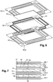
- the figures 5 and 6 illustrate through exploded views such an assembly, with an electrochemical cell 40 SOEC or SOFC arranged inside the insulating frame 60 and arranged between interconnectors 50.2, 50.3.
- the cell 40 may itself be coated near its edges with a material 41 of the glass or glass-ceramic type forming an insulation and sealing gasket.
- an interconnector 50.2 may itself be interposed between two insulating supports 60.1, 60.2 of the type of those described above.
- the same interconnector 50.2 can be provided with a rough region 52 on its first face 50A (in the example illustrated its upper face), and with a rough region on a second face 50B (here its lower face) opposite to the first face 50A, each of these rough regions 52 being in contact with a material 77 of glass or glass-ceramic type forming an insulation and sealing joint.
Landscapes
- Chemical & Material Sciences (AREA)
- Sustainable Energy (AREA)
- Life Sciences & Earth Sciences (AREA)
- Engineering & Computer Science (AREA)
- Manufacturing & Machinery (AREA)
- Sustainable Development (AREA)
- Chemical Kinetics & Catalysis (AREA)
- Electrochemistry (AREA)
- General Chemical & Material Sciences (AREA)
- Inorganic Chemistry (AREA)
- Fuel Cell (AREA)
- Electrolytic Production Of Non-Metals, Compounds, Apparatuses Therefor (AREA)
- Gasket Seals (AREA)
Applications Claiming Priority (2)
| Application Number | Priority Date | Filing Date | Title |
|---|---|---|---|
| FR1762483A FR3075479B1 (fr) | 2017-12-19 | 2017-12-19 | Interconnecteur a etat de surface degrade pour la tenue des etancheites |
| PCT/FR2018/053296 WO2019122631A1 (fr) | 2017-12-19 | 2018-12-14 | Interconnecteur a etat de surface degrade pour la tenue des etancheites |
Publications (2)
| Publication Number | Publication Date |
|---|---|
| EP3729548A1 EP3729548A1 (fr) | 2020-10-28 |
| EP3729548B1 true EP3729548B1 (fr) | 2021-11-03 |
Family
ID=62091981
Family Applications (1)
| Application Number | Title | Priority Date | Filing Date |
|---|---|---|---|
| EP18842427.9A Active EP3729548B1 (fr) | 2017-12-19 | 2018-12-14 | Interconnecteur à état de surface dégradé pour la tenue des étanchéités |
Country Status (7)
| Country | Link |
|---|---|
| US (1) | US11322753B2 (da) |
| EP (1) | EP3729548B1 (da) |
| JP (1) | JP7241755B2 (da) |
| CA (1) | CA3082392A1 (da) |
| DK (1) | DK3729548T3 (da) |
| FR (1) | FR3075479B1 (da) |
| WO (1) | WO2019122631A1 (da) |
Cited By (2)
| Publication number | Priority date | Publication date | Assignee | Title |
|---|---|---|---|---|
| WO2025088169A1 (fr) * | 2023-10-25 | 2025-05-01 | Commissariat A L'energie Atomique Et Aux Energies Alternatives | Procédé de fabrication de réacteur électrochimique à oxyde solide comportant un support isolant électrique assemblé |
| WO2025088170A1 (fr) * | 2023-10-25 | 2025-05-01 | Commissariat A L'energie Atomique Et Aux Energies Alternatives | Procédé de fabrication de réacteur électrochimique à oxyde solide comportant des assemblages d'étanchéité et d'isolation à triple couche |
Families Citing this family (2)
| Publication number | Priority date | Publication date | Assignee | Title |
|---|---|---|---|---|
| JP7058686B2 (ja) * | 2020-04-03 | 2022-04-22 | コリア インスティテゥート オブ エナジー リサーチ | 一体型集電板を用いた固体酸化物燃料電池及びその製造方法 |
| EP4105360A3 (en) | 2021-05-18 | 2022-12-28 | Bloom Energy Corporation | Electrolyzer system with steam generation and method of operating same |
Family Cites Families (9)
| Publication number | Priority date | Publication date | Assignee | Title |
|---|---|---|---|---|
| DE3226652A1 (de) | 1982-07-16 | 1984-01-19 | Mathias 4815 Schloss Holte Mitter | Verfahren und vorrichtung zum faerben, drucken, behandeln oder beschichten einer warenbahn od.dgl. mit unterschiedlichen faser- oder fadenanteilen |
| JP2004513500A (ja) | 2000-11-08 | 2004-04-30 | グローバル サーモエレクトリック インコーポレイテッド | 電気化学電池の連結装置 |
| US20030194369A1 (en) * | 2002-04-16 | 2003-10-16 | Ravi Prasad | Gas generation system |
| FR2947540B1 (fr) | 2009-07-03 | 2012-01-06 | Commissariat Energie Atomique | Compositions de verre pour joints d'appareils fonctionnant a de hautes temperatures et procede d'assemblage les utilisant. |
| WO2011122010A1 (ja) * | 2010-03-30 | 2011-10-06 | 株式会社日本触媒 | 固体酸化物形燃料電池用電解質シートおよびその製造方法、並びに、固体酸化物形燃料電池用単セルおよび固体酸化物形燃料電池 |
| FR2988916B1 (fr) | 2012-03-27 | 2019-11-08 | Commissariat A L'energie Atomique Et Aux Energies Alternatives | Joint d'etancheite preservant l'integrite de cellules electrochimiques, et ses procedes de fabrication et d'utilisation |
| FR3000108B1 (fr) | 2012-12-21 | 2015-02-27 | Commissariat Energie Atomique | Cadre d'isolation electrique et d'etancheite pour reacteur d'electrolyse de l'eau (soec) ou pile a combustible (sofc). |
| FR3014246B1 (fr) | 2013-12-04 | 2016-01-01 | Commissariat Energie Atomique | Joint d'etancheite pour dispositif electrochimique, procede de fabrication et d'assemblage du joint et ce dispositif. |
| JP2016035810A (ja) * | 2014-08-01 | 2016-03-17 | パナソニックIpマネジメント株式会社 | セパレータ−シール部材接合体及び燃料電池 |
-
2017
- 2017-12-19 FR FR1762483A patent/FR3075479B1/fr active Active
-
2018
- 2018-12-14 EP EP18842427.9A patent/EP3729548B1/fr active Active
- 2018-12-14 WO PCT/FR2018/053296 patent/WO2019122631A1/fr not_active Ceased
- 2018-12-14 JP JP2020533657A patent/JP7241755B2/ja active Active
- 2018-12-14 US US16/769,876 patent/US11322753B2/en active Active
- 2018-12-14 CA CA3082392A patent/CA3082392A1/fr active Pending
- 2018-12-14 DK DK18842427.9T patent/DK3729548T3/da active
Cited By (4)
| Publication number | Priority date | Publication date | Assignee | Title |
|---|---|---|---|---|
| WO2025088169A1 (fr) * | 2023-10-25 | 2025-05-01 | Commissariat A L'energie Atomique Et Aux Energies Alternatives | Procédé de fabrication de réacteur électrochimique à oxyde solide comportant un support isolant électrique assemblé |
| WO2025088170A1 (fr) * | 2023-10-25 | 2025-05-01 | Commissariat A L'energie Atomique Et Aux Energies Alternatives | Procédé de fabrication de réacteur électrochimique à oxyde solide comportant des assemblages d'étanchéité et d'isolation à triple couche |
| FR3154869A1 (fr) * | 2023-10-25 | 2025-05-02 | Commissariat A L'energie Atomique Et Aux Energies Alternatives | Procédé de fabrication de réacteur électrochimique à oxyde solide comportant un support isolant électrique assemblé |
| FR3154867A1 (fr) * | 2023-10-25 | 2025-05-02 | Commissariat A L'energie Atomique Et Aux Energies Alternatives | Procédé de fabrication de réacteur électrochimique à oxyde solide comportant des assemblages d’étanchéité et d’isolation à triple couche |
Also Published As
| Publication number | Publication date |
|---|---|
| EP3729548A1 (fr) | 2020-10-28 |
| CA3082392A1 (fr) | 2019-06-27 |
| US11322753B2 (en) | 2022-05-03 |
| DK3729548T3 (da) | 2022-01-31 |
| FR3075479A1 (fr) | 2019-06-21 |
| US20210175518A1 (en) | 2021-06-10 |
| JP2021508151A (ja) | 2021-02-25 |
| WO2019122631A1 (fr) | 2019-06-27 |
| JP7241755B2 (ja) | 2023-03-17 |
| FR3075479B1 (fr) | 2021-09-03 |
Similar Documents
| Publication | Publication Date | Title |
|---|---|---|
| EP3729548A1 (fr) | Interconnecteur a etat de surface degrade pour la tenue des etancheites | |
| EP1959502A1 (fr) | Module photovoltaïque et modules de production d'énergie ou de lumière | |
| EP3562972B1 (fr) | Système de couplage étanche à haute température d'un empilement à oxydes solides de type soec/sofc | |
| EP2593990B1 (fr) | Dispositif de connexion électrique à conductance ameliorée | |
| EP2501888A1 (fr) | Procede de fabrication d'un vitrage isolant | |
| FR3014246A1 (fr) | Joint d'etancheite pour dispositif electrochimique, procede de fabrication et d'assemblage du joint et ce dispositif. | |
| EP2288832A1 (fr) | ASSEMBLAGE COMPORTANT UN JOINT D'ETANCHEITE INTERCALE ENTRE DEUX COMPOSANTS DE COEFFICIENT DE DILATATION MOYEN THERMIQUE DIFFERENT, JOINT D'ETANCHEITE ASSOCIE, APPLICATION A l'ETANCHEITE D'ELECTROLYSEURS EHT ET DES PILES A COMBUSTIBLE SOFC | |
| CA3084431A1 (fr) | Ensemble d'un empilement a oxydes solides de type soec/sofc, d'un systeme de serrage et d'un systeme de couplage etanche | |
| FR3056337A1 (fr) | Reacteur d'electrolyse de l'eau (soec) ou pile a combustible (sofc) a taux d'utilisation de vapeur d'eau ou respectivement de combustible augmente | |
| WO2011048056A1 (fr) | Joint d'etancheite entre deux elements a coefficients de dilatation thermique differents | |
| EP2231901A1 (fr) | Liaison souple etanche entre un substrat metallique et un substrat ceramique, procede de realisation d'une telle liaison, application du procede a l'etancheite d'electrolyseurs haute temperature et des piles a combustible | |
| JP2015525364A (ja) | 耐久性ソーラーミラーフィルム | |
| EP3071722B1 (fr) | Procédé intégré de frittage pour microfissuration et tenue à l'érosion des barrières thermiques | |
| EP2036101A2 (fr) | Procede de fabrication par brasage diffusion des connexions electriques d'un ensemble de stockage d'energie electrique | |
| JP2015525363A (ja) | 耐久性ソーラーミラーフィルム | |
| EP2914883B1 (fr) | Joint statique métallique annulaire performant a bas coût pour hautes pressions et grands diamètres | |
| EP0615074A1 (fr) | Garnitures de frein à plots à fixation améliorée | |
| WO2020128322A1 (fr) | Plaque bipolaire pour pile a combustible | |
| FR2763963A1 (fr) | Procede et dispositif d'etancheification dans une cellule d'electrolyse | |
| FR3155541A1 (fr) | Unité électrodique réalisée par soudage ultrasonore, cellule électrolytique et électrolyseur en comportant, et procédé de fabrication | |
| WO2025237943A1 (fr) | Procédé de fabrication d'interconnecteurs pour dispositifs électrochimiques à oxyde solide et interconnecteur pour dispositifs électrochimiques à oxyde solide | |
| WO2024056980A1 (fr) | Procédé de soudage par point | |
| TWM503056U (zh) | 用於電漿反應裝置之襯套單元 | |
| EP2211382A2 (fr) | Barrière étanche pour microcomposant et procédé de fabrication d'une telle barrière |
Legal Events
| Date | Code | Title | Description |
|---|---|---|---|
| STAA | Information on the status of an ep patent application or granted ep patent |
Free format text: STATUS: UNKNOWN |
|
| STAA | Information on the status of an ep patent application or granted ep patent |
Free format text: STATUS: THE INTERNATIONAL PUBLICATION HAS BEEN MADE |
|
| PUAI | Public reference made under article 153(3) epc to a published international application that has entered the european phase |
Free format text: ORIGINAL CODE: 0009012 |
|
| STAA | Information on the status of an ep patent application or granted ep patent |
Free format text: STATUS: REQUEST FOR EXAMINATION WAS MADE |
|
| 17P | Request for examination filed |
Effective date: 20200625 |
|
| AK | Designated contracting states |
Kind code of ref document: A1 Designated state(s): AL AT BE BG CH CY CZ DE DK EE ES FI FR GB GR HR HU IE IS IT LI LT LU LV MC MK MT NL NO PL PT RO RS SE SI SK SM TR |
|
| AX | Request for extension of the european patent |
Extension state: BA ME |
|
| DAV | Request for validation of the european patent (deleted) | ||
| DAX | Request for extension of the european patent (deleted) | ||
| GRAP | Despatch of communication of intention to grant a patent |
Free format text: ORIGINAL CODE: EPIDOSNIGR1 |
|
| STAA | Information on the status of an ep patent application or granted ep patent |
Free format text: STATUS: GRANT OF PATENT IS INTENDED |
|
| INTG | Intention to grant announced |
Effective date: 20210708 |
|
| GRAS | Grant fee paid |
Free format text: ORIGINAL CODE: EPIDOSNIGR3 |
|
| GRAA | (expected) grant |
Free format text: ORIGINAL CODE: 0009210 |
|
| STAA | Information on the status of an ep patent application or granted ep patent |
Free format text: STATUS: THE PATENT HAS BEEN GRANTED |
|
| AK | Designated contracting states |
Kind code of ref document: B1 Designated state(s): AL AT BE BG CH CY CZ DE DK EE ES FI FR GB GR HR HU IE IS IT LI LT LU LV MC MK MT NL NO PL PT RO RS SE SI SK SM TR |
|
| REG | Reference to a national code |
Ref country code: GB Ref legal event code: FG4D Free format text: NOT ENGLISH |
|
| REG | Reference to a national code |
Ref country code: AT Ref legal event code: REF Ref document number: 1444789 Country of ref document: AT Kind code of ref document: T Effective date: 20211115 Ref country code: CH Ref legal event code: EP |
|
| REG | Reference to a national code |
Ref country code: DE Ref legal event code: R096 Ref document number: 602018026247 Country of ref document: DE |
|
| REG | Reference to a national code |
Ref country code: IE Ref legal event code: FG4D Free format text: LANGUAGE OF EP DOCUMENT: FRENCH |
|
| REG | Reference to a national code |
Ref country code: DK Ref legal event code: T3 Effective date: 20220128 |
|
| REG | Reference to a national code |
Ref country code: LT Ref legal event code: MG9D |
|
| REG | Reference to a national code |
Ref country code: NL Ref legal event code: MP Effective date: 20211103 |
|
| REG | Reference to a national code |
Ref country code: AT Ref legal event code: MK05 Ref document number: 1444789 Country of ref document: AT Kind code of ref document: T Effective date: 20211103 |
|
| PG25 | Lapsed in a contracting state [announced via postgrant information from national office to epo] |
Ref country code: RS Free format text: LAPSE BECAUSE OF FAILURE TO SUBMIT A TRANSLATION OF THE DESCRIPTION OR TO PAY THE FEE WITHIN THE PRESCRIBED TIME-LIMIT Effective date: 20211103 Ref country code: LT Free format text: LAPSE BECAUSE OF FAILURE TO SUBMIT A TRANSLATION OF THE DESCRIPTION OR TO PAY THE FEE WITHIN THE PRESCRIBED TIME-LIMIT Effective date: 20211103 Ref country code: FI Free format text: LAPSE BECAUSE OF FAILURE TO SUBMIT A TRANSLATION OF THE DESCRIPTION OR TO PAY THE FEE WITHIN THE PRESCRIBED TIME-LIMIT Effective date: 20211103 Ref country code: BG Free format text: LAPSE BECAUSE OF FAILURE TO SUBMIT A TRANSLATION OF THE DESCRIPTION OR TO PAY THE FEE WITHIN THE PRESCRIBED TIME-LIMIT Effective date: 20220203 Ref country code: AT Free format text: LAPSE BECAUSE OF FAILURE TO SUBMIT A TRANSLATION OF THE DESCRIPTION OR TO PAY THE FEE WITHIN THE PRESCRIBED TIME-LIMIT Effective date: 20211103 |
|
| PG25 | Lapsed in a contracting state [announced via postgrant information from national office to epo] |
Ref country code: IS Free format text: LAPSE BECAUSE OF FAILURE TO SUBMIT A TRANSLATION OF THE DESCRIPTION OR TO PAY THE FEE WITHIN THE PRESCRIBED TIME-LIMIT Effective date: 20220303 Ref country code: SE Free format text: LAPSE BECAUSE OF FAILURE TO SUBMIT A TRANSLATION OF THE DESCRIPTION OR TO PAY THE FEE WITHIN THE PRESCRIBED TIME-LIMIT Effective date: 20211103 Ref country code: PT Free format text: LAPSE BECAUSE OF FAILURE TO SUBMIT A TRANSLATION OF THE DESCRIPTION OR TO PAY THE FEE WITHIN THE PRESCRIBED TIME-LIMIT Effective date: 20220303 Ref country code: PL Free format text: LAPSE BECAUSE OF FAILURE TO SUBMIT A TRANSLATION OF THE DESCRIPTION OR TO PAY THE FEE WITHIN THE PRESCRIBED TIME-LIMIT Effective date: 20211103 Ref country code: NO Free format text: LAPSE BECAUSE OF FAILURE TO SUBMIT A TRANSLATION OF THE DESCRIPTION OR TO PAY THE FEE WITHIN THE PRESCRIBED TIME-LIMIT Effective date: 20220203 Ref country code: NL Free format text: LAPSE BECAUSE OF FAILURE TO SUBMIT A TRANSLATION OF THE DESCRIPTION OR TO PAY THE FEE WITHIN THE PRESCRIBED TIME-LIMIT Effective date: 20211103 Ref country code: LV Free format text: LAPSE BECAUSE OF FAILURE TO SUBMIT A TRANSLATION OF THE DESCRIPTION OR TO PAY THE FEE WITHIN THE PRESCRIBED TIME-LIMIT Effective date: 20211103 Ref country code: HR Free format text: LAPSE BECAUSE OF FAILURE TO SUBMIT A TRANSLATION OF THE DESCRIPTION OR TO PAY THE FEE WITHIN THE PRESCRIBED TIME-LIMIT Effective date: 20211103 Ref country code: GR Free format text: LAPSE BECAUSE OF FAILURE TO SUBMIT A TRANSLATION OF THE DESCRIPTION OR TO PAY THE FEE WITHIN THE PRESCRIBED TIME-LIMIT Effective date: 20220204 Ref country code: ES Free format text: LAPSE BECAUSE OF FAILURE TO SUBMIT A TRANSLATION OF THE DESCRIPTION OR TO PAY THE FEE WITHIN THE PRESCRIBED TIME-LIMIT Effective date: 20211103 |
|
| PG25 | Lapsed in a contracting state [announced via postgrant information from national office to epo] |
Ref country code: SM Free format text: LAPSE BECAUSE OF FAILURE TO SUBMIT A TRANSLATION OF THE DESCRIPTION OR TO PAY THE FEE WITHIN THE PRESCRIBED TIME-LIMIT Effective date: 20211103 Ref country code: SK Free format text: LAPSE BECAUSE OF FAILURE TO SUBMIT A TRANSLATION OF THE DESCRIPTION OR TO PAY THE FEE WITHIN THE PRESCRIBED TIME-LIMIT Effective date: 20211103 Ref country code: RO Free format text: LAPSE BECAUSE OF FAILURE TO SUBMIT A TRANSLATION OF THE DESCRIPTION OR TO PAY THE FEE WITHIN THE PRESCRIBED TIME-LIMIT Effective date: 20211103 Ref country code: EE Free format text: LAPSE BECAUSE OF FAILURE TO SUBMIT A TRANSLATION OF THE DESCRIPTION OR TO PAY THE FEE WITHIN THE PRESCRIBED TIME-LIMIT Effective date: 20211103 Ref country code: CZ Free format text: LAPSE BECAUSE OF FAILURE TO SUBMIT A TRANSLATION OF THE DESCRIPTION OR TO PAY THE FEE WITHIN THE PRESCRIBED TIME-LIMIT Effective date: 20211103 |
|
| REG | Reference to a national code |
Ref country code: DE Ref legal event code: R097 Ref document number: 602018026247 Country of ref document: DE |
|
| PG25 | Lapsed in a contracting state [announced via postgrant information from national office to epo] |
Ref country code: MC Free format text: LAPSE BECAUSE OF FAILURE TO SUBMIT A TRANSLATION OF THE DESCRIPTION OR TO PAY THE FEE WITHIN THE PRESCRIBED TIME-LIMIT Effective date: 20211103 |
|
| PLBE | No opposition filed within time limit |
Free format text: ORIGINAL CODE: 0009261 |
|
| STAA | Information on the status of an ep patent application or granted ep patent |
Free format text: STATUS: NO OPPOSITION FILED WITHIN TIME LIMIT |
|
| REG | Reference to a national code |
Ref country code: BE Ref legal event code: MM Effective date: 20211231 |
|
| 26N | No opposition filed |
Effective date: 20220804 |
|
| PG25 | Lapsed in a contracting state [announced via postgrant information from national office to epo] |
Ref country code: LU Free format text: LAPSE BECAUSE OF NON-PAYMENT OF DUE FEES Effective date: 20211214 Ref country code: IE Free format text: LAPSE BECAUSE OF NON-PAYMENT OF DUE FEES Effective date: 20211214 Ref country code: AL Free format text: LAPSE BECAUSE OF FAILURE TO SUBMIT A TRANSLATION OF THE DESCRIPTION OR TO PAY THE FEE WITHIN THE PRESCRIBED TIME-LIMIT Effective date: 20211103 |
|
| PG25 | Lapsed in a contracting state [announced via postgrant information from national office to epo] |
Ref country code: SI Free format text: LAPSE BECAUSE OF FAILURE TO SUBMIT A TRANSLATION OF THE DESCRIPTION OR TO PAY THE FEE WITHIN THE PRESCRIBED TIME-LIMIT Effective date: 20211103 Ref country code: BE Free format text: LAPSE BECAUSE OF NON-PAYMENT OF DUE FEES Effective date: 20211231 |
|
| P01 | Opt-out of the competence of the unified patent court (upc) registered |
Effective date: 20230518 |
|
| PG25 | Lapsed in a contracting state [announced via postgrant information from national office to epo] |
Ref country code: CY Free format text: LAPSE BECAUSE OF FAILURE TO SUBMIT A TRANSLATION OF THE DESCRIPTION OR TO PAY THE FEE WITHIN THE PRESCRIBED TIME-LIMIT Effective date: 20211103 |
|
| PG25 | Lapsed in a contracting state [announced via postgrant information from national office to epo] |
Ref country code: HU Free format text: LAPSE BECAUSE OF FAILURE TO SUBMIT A TRANSLATION OF THE DESCRIPTION OR TO PAY THE FEE WITHIN THE PRESCRIBED TIME-LIMIT; INVALID AB INITIO Effective date: 20181214 |
|
| REG | Reference to a national code |
Ref country code: GB Ref legal event code: 732E Free format text: REGISTERED BETWEEN 20240111 AND 20240117 |
|
| PG25 | Lapsed in a contracting state [announced via postgrant information from national office to epo] |
Ref country code: MK Free format text: LAPSE BECAUSE OF FAILURE TO SUBMIT A TRANSLATION OF THE DESCRIPTION OR TO PAY THE FEE WITHIN THE PRESCRIBED TIME-LIMIT Effective date: 20211103 |
|
| PG25 | Lapsed in a contracting state [announced via postgrant information from national office to epo] |
Ref country code: TR Free format text: LAPSE BECAUSE OF FAILURE TO SUBMIT A TRANSLATION OF THE DESCRIPTION OR TO PAY THE FEE WITHIN THE PRESCRIBED TIME-LIMIT Effective date: 20211103 |
|
| PG25 | Lapsed in a contracting state [announced via postgrant information from national office to epo] |
Ref country code: MT Free format text: LAPSE BECAUSE OF FAILURE TO SUBMIT A TRANSLATION OF THE DESCRIPTION OR TO PAY THE FEE WITHIN THE PRESCRIBED TIME-LIMIT Effective date: 20211103 |
|
| REG | Reference to a national code |
Ref country code: CH Ref legal event code: U11 Free format text: ST27 STATUS EVENT CODE: U-0-0-U10-U11 (AS PROVIDED BY THE NATIONAL OFFICE) Effective date: 20260101 |
|
| PGFP | Annual fee paid to national office [announced via postgrant information from national office to epo] |
Ref country code: GB Payment date: 20251229 Year of fee payment: 8 |
|
| PGFP | Annual fee paid to national office [announced via postgrant information from national office to epo] |
Ref country code: DK Payment date: 20251217 Year of fee payment: 8 |
|
| PGFP | Annual fee paid to national office [announced via postgrant information from national office to epo] |
Ref country code: FR Payment date: 20251222 Year of fee payment: 8 |
|
| PGFP | Annual fee paid to national office [announced via postgrant information from national office to epo] |
Ref country code: DE Payment date: 20251222 Year of fee payment: 8 |
|
| PGFP | Annual fee paid to national office [announced via postgrant information from national office to epo] |
Ref country code: IT Payment date: 20251231 Year of fee payment: 8 |
|
| PGFP | Annual fee paid to national office [announced via postgrant information from national office to epo] |
Ref country code: CH Payment date: 20260101 Year of fee payment: 8 |