EP3729604B1 - Ensemble comprenant un boîtier et un stator inséré à l'intérieur dudit boîtier - Google Patents
Ensemble comprenant un boîtier et un stator inséré à l'intérieur dudit boîtier Download PDFInfo
- Publication number
- EP3729604B1 EP3729604B1 EP18811449.0A EP18811449A EP3729604B1 EP 3729604 B1 EP3729604 B1 EP 3729604B1 EP 18811449 A EP18811449 A EP 18811449A EP 3729604 B1 EP3729604 B1 EP 3729604B1
- Authority
- EP
- European Patent Office
- Prior art keywords
- point
- symmetry
- plane
- stator
- housing
- Prior art date
- Legal status (The legal status is an assumption and is not a legal conclusion. Google has not performed a legal analysis and makes no representation as to the accuracy of the status listed.)
- Active
Links
Images


Classifications
-
- H—ELECTRICITY
- H02—GENERATION; CONVERSION OR DISTRIBUTION OF ELECTRIC POWER
- H02K—DYNAMO-ELECTRIC MACHINES
- H02K1/00—Details of the magnetic circuit
- H02K1/06—Details of the magnetic circuit characterised by the shape, form or construction
- H02K1/12—Stationary parts of the magnetic circuit
- H02K1/18—Means for mounting or fastening magnetic stationary parts on to, or to, the stator structures
- H02K1/185—Means for mounting or fastening magnetic stationary parts on to, or to, the stator structures to outer stators
-
- B—PERFORMING OPERATIONS; TRANSPORTING
- B63—SHIPS OR OTHER WATERBORNE VESSELS; RELATED EQUIPMENT
- B63H—MARINE PROPULSION OR STEERING
- B63H5/00—Arrangements on vessels of propulsion elements directly acting on water
- B63H5/07—Arrangements on vessels of propulsion elements directly acting on water of propellers
- B63H5/125—Arrangements on vessels of propulsion elements directly acting on water of propellers movably mounted with respect to hull, e.g. adjustable in direction, e.g. podded azimuthing thrusters
-
- H—ELECTRICITY
- H02—GENERATION; CONVERSION OR DISTRIBUTION OF ELECTRIC POWER
- H02K—DYNAMO-ELECTRIC MACHINES
- H02K5/00—Casings; Enclosures; Supports
- H02K5/04—Casings or enclosures characterised by the shape, form or construction thereof
-
- B—PERFORMING OPERATIONS; TRANSPORTING
- B63—SHIPS OR OTHER WATERBORNE VESSELS; RELATED EQUIPMENT
- B63H—MARINE PROPULSION OR STEERING
- B63H5/00—Arrangements on vessels of propulsion elements directly acting on water
- B63H5/07—Arrangements on vessels of propulsion elements directly acting on water of propellers
- B63H5/125—Arrangements on vessels of propulsion elements directly acting on water of propellers movably mounted with respect to hull, e.g. adjustable in direction, e.g. podded azimuthing thrusters
- B63H2005/1254—Podded azimuthing thrusters, i.e. podded thruster units arranged inboard for rotation about vertical axis
- B63H2005/1258—Podded azimuthing thrusters, i.e. podded thruster units arranged inboard for rotation about vertical axis with electric power transmission to propellers, i.e. with integrated electric propeller motors
-
- H—ELECTRICITY
- H02—GENERATION; CONVERSION OR DISTRIBUTION OF ELECTRIC POWER
- H02K—DYNAMO-ELECTRIC MACHINES
- H02K1/00—Details of the magnetic circuit
- H02K1/06—Details of the magnetic circuit characterised by the shape, form or construction
- H02K1/22—Rotating parts of the magnetic circuit
- H02K1/27—Rotor cores with permanent magnets
- H02K1/2706—Inner rotors
- H02K1/272—Inner rotors the magnetisation axis of the magnets being perpendicular to the rotor axis
- H02K1/2726—Inner rotors the magnetisation axis of the magnets being perpendicular to the rotor axis the rotor consisting of a single magnet or two or more axially juxtaposed single magnets
- H02K1/2733—Annular magnets
-
- H—ELECTRICITY
- H02—GENERATION; CONVERSION OR DISTRIBUTION OF ELECTRIC POWER
- H02K—DYNAMO-ELECTRIC MACHINES
- H02K15/00—Processes or apparatus specially adapted for manufacturing, assembling, maintaining or repairing of dynamo-electric machines
- H02K15/02—Processes or apparatus specially adapted for manufacturing, assembling, maintaining or repairing of dynamo-electric machines of stator or rotor bodies
-
- H—ELECTRICITY
- H02—GENERATION; CONVERSION OR DISTRIBUTION OF ELECTRIC POWER
- H02K—DYNAMO-ELECTRIC MACHINES
- H02K15/00—Processes or apparatus specially adapted for manufacturing, assembling, maintaining or repairing of dynamo-electric machines
- H02K15/02—Processes or apparatus specially adapted for manufacturing, assembling, maintaining or repairing of dynamo-electric machines of stator or rotor bodies
- H02K15/028—Fastening stator or rotor bodies to casings, supports, shafts or hubs
-
- H—ELECTRICITY
- H02—GENERATION; CONVERSION OR DISTRIBUTION OF ELECTRIC POWER
- H02K—DYNAMO-ELECTRIC MACHINES
- H02K15/00—Processes or apparatus specially adapted for manufacturing, assembling, maintaining or repairing of dynamo-electric machines
- H02K15/14—Casings; Enclosures; Supports
-
- H—ELECTRICITY
- H02—GENERATION; CONVERSION OR DISTRIBUTION OF ELECTRIC POWER
- H02K—DYNAMO-ELECTRIC MACHINES
- H02K2213/00—Specific aspects, not otherwise provided for and not covered by codes H02K2201/00 - H02K2211/00
- H02K2213/03—Machines characterised by numerical values, ranges, mathematical expressions or similar information
Definitions
- the present invention relates to an assembly comprising a hollow housing and a stator inserted inside said housing, and more particularly such an assembly intended to be incorporated into a nacelle thruster.
- a nacelle thruster conventionally comprises an electric motor.
- the electric motor notably comprises a rotor rotatably mounted relative to a stator.
- the stator forms an integral assembly with a nacelle propeller housing.
- a housing comprising a cylindrical cavity is heated so as to cause the volume of the cylindrical cavity to increase.
- the stator is inserted inside the housing cavity. When the case cools, the stator is shrunk in the cavity and made integral with the case.
- the housing is likely to be subjected to significant shocks.
- a housing intended for a thruster in the nacelle of an ice-breaking ship is likely to frequently come into contact with blocks of ice. This results in the appearance of significant deformations and vibrations on the housing. These deformations and/or these vibrations are transmitted to the shrouded stator inside the housing. The resulting deformations and/or vibrations of the stator can lead to failure of the electric motor.
- the invention aims to enable the production of an integral assembly comprising a housing and a stator, easy to assemble, removable and in which the impact of shocks on the housing generates as little damage as possible. deformations and vibrations on the stator.
- an assembly comprising a housing and a stator inserted inside a cylindrical cavity of said housing, according to claim 1.
- the present invention is particularly advantageous when the assembly is intended to be incorporated into a propeller in a marine vehicle nacelle.
- the thruster housings are particularly subject to shocks on the lateral faces tending to give the housing an oval shape.
- four zones deform slightly and constitute ideal zones for incorporating a point fixing means.
- the invention can be applied to other fields of application.
- said point fixing means is capable of implementing a holding force directed in the radial direction and/or a holding force directed in the tangential direction.
- the assembly further comprises a first plane of symmetry, said point fixing means being located in an angular sector forming an angle between 0° and 40° with said first plane of symmetry or in an angular sector forming an angle of between 140° and 180° with said first plane of symmetry.
- Such angular sectors correspond to zones of minimal deformation when the housing is affected by shocks occurring on its lateral surfaces. By choosing such angular sectors, the transmission of deformations and/or vibrations from the housing to the stator is thus minimized.
- Such an assembly is therefore particularly suitable for being incorporated into nacelle thrusters intended for icebreaker ships.
- At least one pressure bolt located in an angular sector forming an angle of between 1.5° and 6.5° with said first plane of symmetry, and at least one pressure surface located in an angular sector forming an angle between 155° and 180° with said first plane of symmetry.
- This pressure bolt and this pressure surface make it possible to increase the robustness of the holding force directed in the radial direction. Furthermore, their location in the aforementioned angular sectors makes it easier for an operator to access the pressure bolts.
- the stator comprises two end flanges respectively located at the two axial ends of the stator, said assembly comprising, for each end flange of the stator, a first point fixing means located in an angular sector forming an angle between 0° and 40° with said first plane of symmetry, a second point fixing means located to be symmetrical to the first point fixing means with respect to the first plane of symmetry, a third point fixing means located in an angular sector forming an angle between 140° and 180° with said first plane of symmetry, and a fourth point fixing means located to be the symmetrical of the third point fixing means relative to the first plane of symmetry.
- the embedding connection between the housing and the stator is made robust while minimizing the transmission of deformations and/or vibrations from the housing to the stator. Furthermore, it is possible to ventilate the stator due to the small surface area of the stator in contact with the housing.
- the point fixing means located at a flange at an axial end of the stator are made easy to access.
- the stator comprises at least one intermediate flange axially located between the end flanges, said assembly comprising, for each intermediate flange of the stator, a first point fixing means located in an angular sector forming an angle between 0° and 40° with said first plane of symmetry and a second point fixing means located to be symmetrical to the first point fixing means with respect to the first plane of symmetry.
- said point fixing means comprises a main body and an angled wedge system capable of selectively securing the main body with the housing and with the stator.
- Such a fixing means can easily be put in place or dismantled, or even tightened. This makes it easier to install, remove or adjust the mounting connection of the housing and the stator.
- said main body comprises a plate and a part with a trapezoidal section
- said point fixing means comprising two pairs of biased wedges respectively located on either side of a second plane of symmetry of the main body, each biased wedge being able to move in translation by relative to the main body in a first direction perpendicular to the plane of the plate, the inclined surface of each biased wedge cooperating with an inclined surface of the part with a trapezoidal section such that the movement in translation along the first direction of said wedge biases by relative to the main body in a direction tending to move said biased wedge away from the plate causes a movement of the biased wedge in translation relative to the main body in a second direction perpendicular to the second plane of symmetry in a direction tending to move it away from the second plane of symmetry.
- each biased wedge the movement of said biased wedge relative to the main body is implemented by means of a respective tightening screw.
- a method according to claim 8 is proposed in which the deformation of the housing of an assembly as defined previously is simulated, said simulation being implemented by means of a finite element model, we determines at least one location of minimum deformation of the cylindrical housing, and the point fixing means is placed at said location of minimum deformation.
- propeller 2 It is schematically represented on the figures 1 to 4 a propeller in a nacelle 2.
- the propeller 2 is intended to be incorporated on a marine vehicle (not shown) such as a ship, a submarine or an oil platform.
- Nacelle thrusters are also known by the Anglo-Saxon name “propulsion oriented drive”, or by the corresponding acronym “POD”.
- the thruster 2 comprises in particular a housing 4 shown in radial section on the figure 1 .
- the base 6 consists of a vector x , of a vector y and a vector z .
- the plane formed by the vectors x And y is horizontal, the vector z being oriented from bottom to top.
- the terms “upper” and “lower” will be understood in this application as being defined in relation to the direction and sense of the vector z .
- the housing 4 is symmetrical with respect to the cutting plane II of the figure 1 .
- Plane II is the plane perpendicular to the vector y containing axis 12.
- Only half of the housing 4 has therefore been represented, the other half being able to be deduced by symmetry with respect to plane II.
- the housing 4 is notably made up of an upper connection portion 8 and a cylindrical portion 10.
- the portion 8 is connected to a part of the marine vehicle, for example to the hull of a ship. More precisely, portion 8 can be secured to a ring of a steering bearing (not shown), the other ring of the steering bearing being secured to the hull of the ship.
- Portion 10 is axisymmetric around an axis 12 parallel to the vector x .
- Portion 10 is radially delimited by a cylindrical wall (not referenced) comprising an interior surface 11.
- Interior surface 11 delimits a cylindrical cavity (not referenced) around the axis 12.
- the portion 10 is axially delimited by a first front wall 14 and by a second front wall 16.
- Each front wall 14, 16 respectively comprises a cylindrical bore 18, 20.
- the bores 18 and 20 are coaxial around the axis 12. of axis 12.
- Bores 18 and 20 are designed to receive a propulsion shaft (not shown).
- the shaft supports a propulsion means which may in particular be a propeller (not shown) or a pump rotor (not shown).
- the housing 4 has three annular flanges 22, 24 and 26.
- the flanges 22, 24 and 26 are substantially identical and extend radially inward from the surface 11.
- the axial offset between the flanges 22 and 24 is substantially equal to the axial offset between flanges 24 and 26.
- the sectional plan of the figure 2 is the plane perpendicular to the vector x containing the flange 22.
- the cutting plane of the Figure 3 is the plane perpendicular to the vector x containing the flange 24.
- the cutting plane of the Figure 4 is the plane perpendicular to the vector x containing the flange 26.
- the thruster 2 comprises an electric motor 28.
- the motor 28 is designed to rotate the propulsion shaft relative to the housing 4.
- the motor 28 comprises a stator 29 and a rotor 32.
- the stator 29 and the rotor 32 are coaxial around the axis 12.
- the stator 29 and the rotor 32 comprise windings of electrically conductive material making it possible to generate an electromagnetic force causing the rotational movement of the rotor 32 relative to the stator 29 around the axis 12.
- the windings constituting the rotor 29 and the stator 32 are impregnated in a matrix by a vacuum and pressure impregnation process. This process is also known by the Anglo-Saxon name “vacuum pressure impregnation”, or by the corresponding acronym “VPI”.
- the stator 29 notably comprises a first portion 30 and a second portion 31.
- the first and second portions 30 and 31 are substantially identical, coaxial around the axis 12.
- the stator 29 comprises a first end flange 34, an intermediate flange 36 and a second end flange 38.
- the flanges 34, 36 and 38 are substantially identical.
- the flange 36 is axially disposed between the portions 30 and 31.
- the flange 34 is disposed at an axial end of the stator 29 adjacent to the portion 30.
- the flange 38 is disposed at an axial end of the stator 29 adjacent to the portion 31.
- flanges 34, 36 and 38 are respectively visible on the figure 2 , 3 And 4 .
- the housing 4 and the stator 29 constitute an integral assembly (E).
- the means will now be described making it possible to produce an integral assembly comprising in particular the housing 4 and the stator 29.
- the thruster 2 comprises four axial stopping means 40.
- two axial stopping means 40 are visible in the sectional view of the figure 1 .
- Each means 40 consists of a plate 42 fixed to the surface 11.
- the plate 42 is secured to a rod 44 in axial contact with the flange 34.
- the four means 40 are designed so as to be able to withstand a maximum axial force of 125 tonnes, or 1250 N. In this way, the axial force tending to move the stator 29 in the direction opposite to that of the vector x , resulting from the action of the propulsion means on the water, is prevented by the four means 40.
- ten point fixing means 46 are provided.
- four means 46 are radially placed between the flanges 22 and 34
- two means 46 are radially placed between the flanges 24 and 36
- four means 46 are radially placed between the flanges 26 and 38.
- the operation of the means 46 is detailed further below.
- the propeller 2 further comprises six radial bores 48.
- the bores 48 receive a bolt pressure 50.
- two bores 48 and two bolts 50 are provided.
- Each bolt 50 can be moved radially relative to the housing 4 so as to exert a radial force on one of the flanges 34 , 36 and 38.
- the flange 26 comprises a pressure surface 52.
- the surface 52 consists of a protuberance extending radially inwardly from the interior cylindrical surface of the flange 26. Due to the small thickness of the protuberance constituting the surface 52, the pressure surfaces 52 of the flanges 22 and 24 are not visible on the figures 1 to 4 .
- the flange 22 comprises two pressure surfaces 52 identical to the surfaces 52 of the Figure 6 and located opposite the two respective bores 48.
- the flange 24 comprises two pressure surfaces 52 which are also identical to the surfaces 52 of the flanges 22 and 26.
- the means 46 located in an upper half of the portion 10 are respectively located in an angular sector oriented between 0° and 40°, and in an angular sector oriented between 0° and -40°, around the axis 12 considering that the vector z corresponds to the zero angle.
- these means 46 are respectively located in an oriented angular sector between 5° and 30° and in an oriented angular sector between -5° and -30°. Even more preferably, these means 46 are respectively located in an oriented angular sector between 8° and 20° and in an oriented angular sector between -8° and -20°.
- the means 46 located in the lower part of the portion 10 are located respectively located in an angular sector oriented between 140° and 180°, and in an angular sector oriented between 180° and 220°, around the axis 12 in considering that the vector z corresponds to the zero angle.
- these means 46 are respectively located in an oriented angular sector between 140° and 166° and in an oriented angular sector between 194° and 220°.
- these means 46 are respectively located in an oriented angular sector between 145° and 162° and in an oriented angular sector between 198° and 215°. More precisely, each means 46 is received in a groove made in the corresponding flange 22, 24 or 26.
- This groove extends radially outwards from the interior cylindrical surface of said flange 22, 24 or 26.
- Said means 46 is also received in a groove made in the corresponding flange 34, 36 or 38. This groove extends radially inwards from the exterior cylindrical surface of said flange 34, 36 or 38.
- an orifice 48 and a bolt 50 are located in an angular sector oriented between 1.5° and 6.5°, around the axis 12 considering that the vector z corresponds to the zero angle, and an orifice 48 and a bolt 50 are located in an oriented angular sector between -1.5° and -6.5°, around the axis 12 considering that the vector z corresponds to the zero angle.
- the couples consisting of an orifice 48 and a bolt 50 are respectively located in an oriented angular sector of between 3° and 5° and in an oriented angular sector of between -3° and - 5°.
- a pressure surface 52 is located in an angular sector oriented between 155° and 180°, around the axis 12 considering that the vector z corresponds to the zero angle, and a pressure surface is located in an oriented angular sector between 180° and 205°, around axis 12 considering that the vector z corresponds to the zero angle.
- the pressure surfaces 52 are respectively located in an oriented angular sector between 160° and 172° and in an oriented angular sector between 188° and 200°.
- the means 46 comprises a main body 54.
- An orthonormal vector base 56 is defined attached to the body 54.
- the base 56 is consisting of a vector u , of a vector v and a vector w .
- the body 54 admits a plane of symmetry P symmetry perpendicular to the vector u .
- the body 54 notably comprises a plate 58 perpendicular to the vector v .
- the plate 58 includes two through holes 60.
- the holes 60 are cylindrical around the direction of the vector v .
- the holes 60 are of the same diameter.
- the plate 58 includes four cylindrical openings 62 around the direction of the vector v .
- the holes 62 are of the same smaller diameter than the holes 60.
- the through holes 62 include an internal thread.
- the main body 54 further comprises a part with a trapezoidal section 64.
- the section of the part 64 according to a cutting plane perpendicular to the vector w is a trapezoid whose short side is adjacent to plate 58 and the long side is opposite to plate 58.
- part 64 is delimited by a small rectangular face (not referenced) and by a large rectangular face (not referenced).
- the part 64 is held in contact by its small rectangular surface with the plate 58 by two fixing screws 66.
- the part 64 is kept in contact by its large rectangular surface with a secondary plate 68 by a secondary fixing screw 70.
- the part 64 is delimited by a first inclined surface 72 and by a second inclined surface 74 (referenced on the Figure 7 ).
- the inclined surfaces 72 and 74 form with the vector v two opposite angles.
- the angle formed by the inclined surfaces 72 and 74 with respect to the vector v is between 2.8° and 3.2° in absolute value.
- the means 46 comprises a first pair of biased shims comprising a biased shim 76 and a biased shim 78.
- the shims 76 and 78 are identical. In particular, their section relative to a cutting plane perpendicular to the vector w is a right trapezoid.
- the wedges 76 and 78 include an inclined surface 80 (referenced on the Figure 7 ) forming an angle with respect to the vector v substantially equal to the opposite of the angle between the inclined surface 72 and the vector v .
- the wedges 76 and 78 are respectively located opposite two through-holes 62. Each wedge 76 and 78 can move in translation according to the direction of the vector v relative to the body 54, thanks to four pins 82.
- the pins 82 have sufficient clearance with the wedges 76 and 78 so that the wedges 76 and 78 can also move in translation in the direction of the vector u over a travel width ⁇ u.
- the wedges 76 and 78 are respectively placed opposite two orifices 62.
- a clamping screw (not shown) is used whose shank diameter and thread are adapted to cooperate with the holes 62.
- the bias wedge then moves in the direction of the vector v towards the plate 68.
- this movement causes another movement of the biased wedge in the direction of the vector u and in the opposite direction to that of the vector u .
- you unscrew the tightening screw the bias wedge is free to move in opposite directions.
- the means 46 comprises a second pair of biased wedges consisting of a biased wedge 84 and a biased wedge 86 (not visible in the figures).
- Bias wedges 84 and 86 are identical in design to wedges 76 and 78, and are mechanically connected to the main body in the same manner.
- the wedges 84 and 86 are located on the other side of the wedges 76 and 78 relative to the plane of symmetry P symmetry .
- the fixing means 46 are initially configured as illustrated on the figures 7 to 9 .
- the wedges 76, 78, 84 and 86 are adjacent to the plate 58.
- an operator introduces the means 46 into the grooves of the flanges 22, 24, 26 and into the grooves of the flanges 34, 36 and 38.
- Concerning the means 46 represented on the figures 7 to 9 the means 46 is inserted inside a groove of the flange 26 and a groove of the flange 38. More precisely, the wedges 76 and 84 are introduced into the groove of the flange 26 while the biased wedges 78 and 86 are inserted into the groove of flange 38.
- the wedges 76, 78, 84 and 86 move according to the direction and direction of the vector v until it abuts against the plate 68. Thanks to the inclined surfaces 72 and 80, the wedges 76, 78, 84 and 86 move in the direction of the vector u so as to move away from the plane of symmetry of the main body 54. In fact, the wedges 76 and 78 move in the opposite direction to the direction of the vector u while the wedges 84 and 86 move in the direction of the vector u . We thus increase the thickness of the means 46 according to the direction of the vector u with a value of up to 2* ⁇ u.
- the wedges 76 and 84 then exert a normal force on the walls of the groove of the flange 26. A tangential friction force is produced fixing the fixing means 46 to the housing 4. Likewise, the wedges 78 and 86 exert a force normal on the groove of the flange 38. The tangential friction force appearing fixes the means 46 to the stator 29. Thanks to the contacts of the wedges 76 and 84 with the flange 26 and of the wedges 78 and 86 with the flange 38, we adjust a to a fixing means 46 so as to fix the stator 29 on the housing 4 while avoiding hyperstatism.
- Shims 76, 78, 84 and 86 will return to their initial position as illustrated on the figures 7 to 9 .
- the means 46 can then be easily removed.
- the propeller 2 With the propeller 2, it is possible to produce the integral assembly (E) consisting in particular of the housing 4 and the stator 29.
- the point fixing means producing the assembly (E) are placed in judiciously chosen locations, namely on upper and lower portions of the end flanges and on upper portions of the intermediate flange, and in precise angular sectors around axis 12.
- the transmission of deformations and/or vibrations from the housing 4 to the stator 29 are made minimal.
- the production of the assembly (E) is facilitated, it is possible to dismantle the assembly (E) and readjust the robustness of the mounting connection between the stator 29 and the housing 4.
- a first step we simulate the deformation of the propeller 2 following an impact.
- a second step we determine, for any point of the housing 4, the variation of the relative position of this point with respect to the axis 12. In this way, we can find a location of minimum deformation of the cylindrical housing following of simulated shock. It is advantageous to compare the variations in relative position with respect to the axis 12, because we take into account an overall movement of the propeller 2 so that the minimum deformation locations are identified more quickly.
- ten locations of minimum deformation are determined. Four locations of minimum deformation are located on the flange 22, two locations of minimum deformation are located on the flange 24 and two locations of minimum deformation are located on the flange 26.
- the point fixing means 46 are placed at each location of minimum deformation. More particularly, grooves are made in the flanges 22, 24 and 26 at the locations of minimum deformation. Grooves are then made in the flanges 34, 36 and 38 in angular sectors corresponding to the angular sectors of the minimum deformation locations. Point fixing means are then placed in the grooves made.
Landscapes
- Engineering & Computer Science (AREA)
- Power Engineering (AREA)
- Manufacturing & Machinery (AREA)
- Chemical & Material Sciences (AREA)
- Combustion & Propulsion (AREA)
- Mechanical Engineering (AREA)
- Ocean & Marine Engineering (AREA)
- Motor Or Generator Frames (AREA)
- Iron Core Of Rotating Electric Machines (AREA)
- Clamps And Clips (AREA)
- Connection Of Plates (AREA)
- Manufacture Of Motors, Generators (AREA)
Description
- La présente invention concerne un ensemble comprenant un boîtier creux et un stator inséré à l'intérieur dudit boîtier, et plus particulièrement un tel ensemble destiné à être incorporé dans un propulseur en nacelle.
- Dans de nombreuses applications, il est nécessaire de réaliser un ensemble solidaire comprenant un boîtier et un stator inséré à l'intérieur du boîtier.
- Par exemple, dans des véhicules marins tels que les navires, les sous-marins ou les plates-formes pétrolières, un propulseur en nacelle comprend de manière classique un moteur électrique. Le moteur électrique comporte notamment un rotor monté rotatif par rapport à un stator. Le stator forme un ensemble solidaire avec un boîtier du propulseur en nacelle.
- De manière classique, pour réaliser un tel ensemble solidaire, on chauffe un boîtier comprenant une cavité cylindrique de sorte à entraîner l'augmentation du volume de la cavité cylindrique. On insère le stator à l'intérieur de la cavité du boîtier. Lors du refroidissement du boîtier, le stator est fretté dans la cavité et rendu solidaire du boîtier.
- De tels ensembles solidaires présentent toutefois l'inconvénient de ne pas être démontables.
- Par ailleurs, dans beaucoup d'applications, le boîtier est susceptible d'être soumis à des chocs importants. Par exemple, un boîtier destiné à un propulseur en nacelle de navire brise-glace est susceptible d'entrer fréquemment en contact avec des blocs de glace. Il en résulte l'apparition de déformations et de vibrations importantes sur le boîtier. Ces déformations et/ou ces vibrations sont transmises au stator fretté à l'intérieur du boîtier. Les déformations et/ou les vibrations du stator qui en résultent peuvent conduire à une défaillance du moteur électrique.
- On peut également se référer aux documents
US 3 708 707 ,US 2005/236924 ) etUS 4 634 909 qui proposent une fixation par clavette d'un stator dans un logement. - Au vu de ce qui précède, l'invention a pour but de permettre la réalisation d'un ensemble solidaire comprenant un boîtier et un stator, facile à monter, démontable et dans lequel l'impact des chocs sur le boîtier engendre le moins possible de déformations et de vibrations sur le stator.
- À cet effet, il est proposé un ensemble comprenant un boîtier et un stator inséré à l'intérieur d'une cavité cylindrique dudit boîtier, selon la revendication 1.
- Grâce à de tels moyens de fixation ponctuels, il est possible de disposer les moyens de fixation dans des zones de déformation minimale du boîtier. On minimise ainsi la transmission des déformations et/ou des vibrations du boîtier au stator. On préserve ainsi au maximum le stator de sorte à limiter le risque d'une défaillance du stator à la suite d'un choc particulièrement fort ou d'une répétition de chocs.
- La présente invention est tout particulièrement avantageuse lorsque l'ensemble est destiné à être incorporé dans un propulseur en nacelle de véhicule marin. En effet, dans une telle application, les boîtiers de propulseur sont particulièrement soumis à des chocs sur les faces latérales tendant à donner au boitier une forme ovale. Dans ce cas, quatre zones se déforment faiblement et constituent des zones idéales pour y incorporer un moyen de fixation ponctuel. Toutefois, on gardera à l'esprit que l'invention peut s'appliquer à d'autres domaines d'application.
- De manière avantageuse, ledit moyen de fixation ponctuel est apte à mettre en oeuvre un effort de maintien dirigé selon la direction radiale et/ou un effort de maintien dirigé selon la direction tangentielle.
- La mise en oeuvre de ces efforts de maintien peut aisément être assurée par un même moyen de fixation ponctuelle. Sauf indication contraire, les termes « axial », « radial » et « tangentiel » doivent être compris comme se référant à un axe de cylindricité du stator.
- Dans un mode de réalisation, l'ensemble comprend en outre un premier plan de symétrie, ledit moyen de fixation ponctuel étant localisé dans un secteur angulaire formant un angle compris entre 0 ° et 40 ° avec ledit premier plan de symétrie ou dans un secteur angulaire formant un angle compris entre 140 ° et 180 ° avec ledit premier plan de symétrie.
- De tels secteurs angulaires correspondent à des zones de déformation minimale lorsque le boîtier est atteint par des chocs se produisant sur ses surfaces latérales. En choisissant de tels secteurs angulaires, on minimise ainsi la transmission des déformations et/ou des vibrations du boîtier sur le stator. Un tel ensemble est donc particulièrement adapté pour être incorporé dans des propulseurs en nacelle destinés à des navires brise glace.
- On peut également prévoir au moins un boulon de pression localisé dans un secteur angulaire formant un angle compris entre 1,5 ° et 6,5 ° avec ledit premier plan de symétrie, et au moins une surface de pression localisée dans un secteur angulaire formant un angle compris entre 155 ° et 180 ° avec ledit premier plan de symétrie.
- Ce boulon de pression et cette surface de pression permettent d'augmenter la robustesse de l'effort de maintien dirigé selon la direction radiale. Par ailleurs, leur localisation dans les secteurs angulaires précités permet de faciliter l'accès d'un opérateur aux boulons de pression.
- Dans un mode de réalisation, le stator comprend deux brides d'extrémité respectivement situées aux deux extrémités axiales du stator, ledit ensemble comprenant, pour chaque bride d'extrémité du stator, un premier moyen de fixation ponctuel localisé dans un secteur angulaire formant un angle compris entre 0 ° et 40 ° avec ledit premier plan de symétrie, un deuxième moyen de fixation ponctuel localisé pour être le symétrique du premier moyen de fixation ponctuel par rapport au premier plan de symétrie, un troisième moyen de fixation ponctuel localisé dans un secteur angulaire formant un angle compris entre 140 ° et 180 ° avec ledit premier plan de symétrie, et un quatrième moyen de fixation ponctuel localisé pour être le symétrique du troisième moyen de fixation ponctuel par rapport au premier plan de symétrie.
- Dans un tel mode de réalisation, la liaison d'encastrement entre le boîtier et le stator est rendue robuste tout en minimisant la transmission des déformations et/ou des vibrations du boîtier au stator. Par ailleurs, il est possible de ventiler le stator du fait de la faible surface du stator en contact avec le boîtier. En outre, les moyens de fixation ponctuels situés au niveau d'une bride à une extrémité axiale du stator sont rendus faciles d'accès.
- Le stator comprend au moins une bride intermédiaire axialement située entre les brides d'extrémité, ledit ensemble comprenant, pour chaque bride intermédiaire du stator, un premier moyen de fixation ponctuel localisé dans un secteur angulaire formant un angle compris entre 0 ° et 40 ° avec ledit premier plan de symétrie et un deuxième moyen de fixation ponctuel localisé pour être le symétrique du premier moyen de fixation ponctuel par rapport au premier plan de symétrie.
- De ce fait, on renforce encore davantage la robustesse de la liaison d'encastrement entre le boîtier et le stator. Du fait que seuls deux moyens de fixation ponctuels sont prévus pour chaque bride intermédiaire, on facilite l'accès à ces moyens de fixation ponctuels.
- Dans un mode de réalisation selon l'invention, ledit moyen de fixation ponctuel comprend un corps principal et un système de cale biaise apte à solidariser de manière sélective le corps principal avec le boîtier et avec le stator.
- Un tel moyen de fixation peut facilement être mis en place ou démonté, ou encore resserré. On facilite ainsi la mise en place, la suppression ou le réglage de la liaison d'encastrement du boîtier et du stator.
- Dans un mode de réalisation selon l'invention, ledit corps principal comprend une platine et une pièce à section trapézoïdale, ledit moyen de fixation ponctuel comprenant deux paires de cales biaises respectivement situées de part et d'autre d'un second plan de symétrie du corps principal, chaque cale biaise étant apte à se déplacer en translation par rapport au corps principal selon une première direction perpendiculaire au plan de la platine, la surface inclinée de chaque cale biaise coopérant avec une surface inclinée de la pièce à section trapézoïdale de telle sorte que le déplacement en translation selon la première direction de ladite cale biaise par rapport au corps principal dans un sens tendant à éloigner ladite cale biaise de la platine occasionne un déplacement de la cale biaise en translation par rapport au corps principal selon une seconde direction perpendiculaire au second plan de symétrie dans un sens tendant à l'éloigner du second plan de symétrie.
- De manière avantageuse, pour chaque cale biaise, le déplacement de ladite cale biaise par rapport au corps principal est mis en oeuvre au moyen d'une vis de serrage respective.
- Selon un autre aspect, il est proposé un procédé selon la revendication 8 dans lequel on simule la déformation du boitier d'un ensemble tel que défini précédemment, ladite simulation étant mise en oeuvre au moyen d'un modèle par éléments finis, l'on détermine au moins une localisation de déformation minimale du boîtier cylindrique, et l'on place le moyen de fixation ponctuel à ladite localisation de déformation minimale.
- D'autres buts, caractéristiques et avantages de l'invention apparaîtront à la lecture de la description suivante, donnée uniquement à titre d'exemple non limitatif, et faite en référence aux dessins annexés sur lesquels :
- la
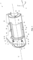
figure 1 est une vue en perspective d'un ensemble selon l'invention, - les
figures 2 ,3 et4 sont respectivement trois vues en coupe de l'ensemble de lafigure 1 , - les
figures 5 et 6 sont deux vues de détail de lafigure 4 , - la
figure 7 est une vue en perspective d'un moyen de fixation ponctuel de l'ensemble desfigures 1 à 6 , - la
figure 8 est une vue de face du moyen de fixation de lafigure 7 , et - la
figure 9 est une vue en coupe selon le plan de coupe IX-IX du moyen de fixation desfigures 7 et8 . - Il est schématiquement représenté sur les
figures 1 à 4 un propulseur en nacelle 2. Le propulseur 2 est destiné à être incorporé sur un véhicule marin (non représenté) tel qu'un navire, un sous-marin ou une plate-forme pétrolière. Les propulseurs en nacelle sont également connus sous la dénomination anglo-saxonne « propulsion oriented drive », ou sous l'acronyme correspondant « POD ». - Le propulseur 2 comporte notamment un boîtier 4 représenté en coupe radiale sur la
figure 1 . On définit une base vectorielle orthonormale 6 attachée au boîtier 4. La base 6 est constituée d'un vecteurx , d'un vecteury et d'un vecteurz . Lorsque le propulseur est normalement incorporé sur un véhicule marin tel qu'un navire en cale sèche, le plan formé par les vecteursx ety est horizontal, le vecteurz étant orienté du bas vers le haut. Sauf indication contraire, les termes « supérieur » et « inférieur » seront compris dans la présente demande comme étant définis par rapport à la direction et au sens du vecteurz . - Le boîtier 4 est symétrique par rapport au plan de coupe I-I de la
figure 1 . Le plan I-I est le plan perpendiculaire au vecteury contenant l'axe 12. Dans un souci de clarté de lafigure 1 , seule la moitié du boîtier 4 a donc été représentée, l'autre moitié pouvant être déduite par symétrie par rapport au plan I-I. - Comme illustré sur la
figure 1 , le boîtier 4 est notamment constitué d'une portion supérieure de raccordement 8 et d'une portion cylindrique 10. La portion 8 est raccordée à une pièce du véhicule marin, par exemple à la coque d'un navire. Plus précisément, la portion 8 peut être solidaire d'une bague d'un palier de gouverne (non représenté), l'autre bague du palier de gouverne étant solidaire de la coque du navire. - La portion 10 est axisymétrique autour d'un axe 12 parallèle au vecteur
x . La portion 10 est radialement délimitée par une paroi cylindrique (non référencée) comprenant une surface intérieure 11. La surface intérieure 11 délimite une cavité cylindrique (non référencée) autour de l'axe 12. La portion 10 est axialement délimitée par une première paroi frontale 14 et par une seconde paroi frontale 16. Chaque paroi frontale 14, 16 comprend respectivement un alésage cylindrique 18, 20. Les alésages 18 et 20 sont coaxiaux autour de l'axe 12. - Les alésages 18 et 20 sont prévus pour recevoir un arbre de propulsion (non représenté). L'arbre supporte un moyen de propulsion pouvant notamment être une hélice (non représentée) ou un rotor de pompe (non représenté).
- Le boîtier 4 comporte trois brides annulaires 22, 24 et 26. Les brides 22, 24 et 26 sont sensiblement identiques et s'étendent radialement vers l'intérieur depuis la surface 11. Le décalage axial entre les brides 22 et 24 est sensiblement égal au décalage axial entre les brides 24 et 26.
- On a schématiquement représenté sur les
figures 2 ,3 et4 des vues en coupe du propulseur 2. Le plan de coupe de lafigure 2 est le plan perpendiculaire au vecteurx contenant la bride 22. Le plan de coupe de lafigure 3 est le plan perpendiculaire au vecteurx contenant la bride 24. Le plan de coupe de lafigure 4 est le plan perpendiculaire au vecteurx contenant la bride 26. - Le propulseur 2 comporte un moteur électrique 28. Le moteur 28 est prévu pour entraîner en rotation l'arbre de propulsion par rapport au boîtier 4. Le moteur 28 comporte un stator 29 et un rotor 32. Le stator 29 et le rotor 32 sont coaxiaux autour de l'axe 12. De manière classique en soi, le stator 29 et le rotor 32 comprennent des enroulements en matériau électriquement conducteur permettant de générer un effort électromagnétique entraînant le déplacement en rotation du rotor 32 par rapport au stator 29 autour de l'axe 12. Dans l'exemple illustré, les enroulements constituant le rotor 29 et le stator 32 sont imprégnés dans une matrice par un procédé d'imprégnation sous vide et sous pression. Ce procédé est également connu sous la dénomination anglo-saxonne « vacuum pressure imprégnation », ou sous l'acronyme correspondant « VPI ».
- Plus particulièrement, dans l'exemple illustré, le stator 29 comprend notamment une première portion 30 et une seconde portion 31. Les première et seconde portions 30 et 31 sont sensiblement identiques, coaxiales autour de l'axe 12.
- Le stator 29 comporte une première bride d'extrémité 34, une bride intermédiaire 36 et une deuxième bride d'extrémité 38. Les brides 34, 36 et 38 sont sensiblement identiques. La bride 36 est axialement disposée entre les portions 30 et 31. La bride 34 est disposée à une extrémité axiale du stator 29 adjacente à la portion 30. La bride 38 est disposée à une extrémité axiale du stator 29 adjacente à la portion 31. Les brides 34, 36 et 38 sont respectivement visibles sur les
figures 2 ,3 et4 . - Selon l'invention, le boîtier 4 et le stator 29 constituent un ensemble solidaire (E). Il va maintenant être décrit les moyens permettant de réaliser un ensemble solidaire comprenant notamment le boîtier 4 et le stator 29.
- Le propulseur 2 comprend quatre moyens d'arrêt axial 40. En l'espèce, deux moyens d'arrêt axial 40 sont visibles sur la vue en coupe de la
figure 1 . Chaque moyen 40 se compose d'une platine 42 fixée à la surface 11. La platine 42 est solidaire d'une tige 44 en contact axial avec la bride 34. Les quatre moyens 40 sont conçus de manière à pouvoir supporter un effort axial maximal de 125 tonnes, ou 1250 N. De cette manière, l'effort axial tendant à déplacer le stator 29 dans le sens opposé à celui du vecteurx , résultant de l'action du moyen de propulsion sur l'eau, est empêché par les quatre moyens 40. - Afin d'assurer le verrouillage selon la direction radiale et selon la direction tangentielle de l'ensemble solidaire, il est prévu dix moyens de fixation ponctuels 46. En l'espèce, quatre moyens 46 sont radialement placés entre les brides 22 et 34, deux moyens 46 sont radialement placés entre les brides 24 et 36 et quatre moyens 46 sont radialement placés entre les brides 26 et 38. Le fonctionnement des moyens 46 est détaillé davantage par la suite.
- Comme illustré sur les
figures 2 à 5 , le propulseur 2 comporte en outre six alésages radiaux 48. Les alésages 48 reçoivent un boulon de pression 50. Pour chaque bride 22, 24 et 26, il est prévu deux alésages 48 et deux boulons 50. Chaque boulon 50 peut être déplacé radialement par rapport au boîtier 4 de manière à exercer un effort radial sur l'une des brides 34, 36 et 38. - Comme illustré sur la
figure 6 , la bride 26 comporte une surface de pression 52. La surface 52 consiste en une protubérance s'étendant en saillie radiale vers l'intérieur depuis la surface cylindrique intérieure de la bride 26. Du fait de la faible épaisseur de la protubérance constituant la surface 52, les surfaces de pression 52 des brides 22 et 24 ne sont pas visibles sur lesfigures 1 à 4 . Toutefois, la bride 22 comprend deux surfaces de pression 52 identiques aux surfaces 52 de lafigure 6 et situées en regard des deux alésages 48 respectifs. De même, la bride 24 comprend deux surfaces de pression 52 elles aussi identiques aux surfaces 52 des brides 22 et 26. - Comme visible sur les
figures 2 à 4 , les moyens 46 situés dans une moitié supérieure de la portion 10 sont respectivement localisés dans un secteur angulaire orienté compris entre 0 ° et 40 °, et dans un secteur angulaire orienté compris entre 0 ° et -40 °, autour de l'axe 12 en considérant que le vecteurz correspond à l'angle nul. De préférence, ces moyens 46 sont respectivement situés dans un secteur angulaire orienté compris entre 5 ° et 30 ° et dans un secteur angulaire orienté compris entre -5 ° et -30 °. De manière encore plus préférentielle, ces moyens 46 sont respectivement situés dans un secteur angulaire orienté compris entre 8 ° et 20 ° et dans un secteur angulaire orienté compris entre -8 ° et -20 °. Les moyens 46 situés dans la partie inférieure de la portion 10 sont localisés respectivement localisées dans un secteur angulaire orienté compris entre 140 ° et 180 °, et dans un secteur angulaire orienté compris entre 180 ° et 220 °, autour de l'axe 12 en considérant que le vecteurz correspond à l'angle nul. De préférence, ces moyens 46 sont respectivement situés dans un secteur angulaire orienté compris entre 140 ° et 166 ° et dans un secteur angulaire orienté compris entre 194 ° et 220 °. De manière encore plus préférentielle, ces moyens 46 sont respectivement situés dans un secteur angulaire orienté compris entre 145 ° et 162 ° et dans un secteur angulaire orienté compris entre 198 ° et 215 °. Plus précisément, chaque moyen 46 est reçu dans une rainure pratiquée dans la bride 22, 24 ou 26 correspondante. Cette rainure s'étend radialement vers l'extérieur depuis la surface cylindrique intérieure de ladite bride 22, 24 ou 26. Ledit moyen 46 est également reçu dans une rainure pratiquée dans la bride 34, 36 ou 38 correspondante. Cette rainure s'étend radialement vers l'intérieur depuis la surface cylindrique extérieure de ladite bride 34, 36 ou 38. - Pour chaque bride 22, 24 ou 26, un orifice 48 et un boulon 50 sont situés dans un secteur angulaire orienté compris entre 1,5 ° et 6,5 °, autour de l'axe 12 en considérant que le vecteur
z correspond à l'angle nul, et un orifice 48 et un boulon 50 sont situés dans un secteur angulaire orienté compris entre -1,5 ° et -6,5 °, autour de l'axe 12 en considérant que le vecteurz correspond à l'angle nul. De préférence, les couples constitués d'un orifice 48 et d'un boulon 50 sont respectivement situés dans un secteur angulaire orienté compris entre 3 ° et 5 ° et dans un secteur angulaire orienté compris entre -3 ° et - 5 °. - Pour chaque bride 22, 24 ou 26, une surface de pression 52 est située dans un secteur angulaire orienté compris entre 155 ° et 180 °, autour de l'axe 12 en considérant que le vecteur
z correspond à l'angle nul, et une surface de pression est située dans un secteur angulaire orienté compris entre 180 ° et 205 °, autour de l'axe 12 en considérant que le vecteurz correspond à l'angle nul. De préférence, les surfaces de pression 52 sont respectivement situées dans un secteur angulaire orienté compris entre 160 ° et 172 ° et dans un secteur angulaire orienté compris entre 188 ° et 200 °. - En référence aux
figures 7 à 9 , on va maintenant détailler un moyen de fixation ponctuel 46. Dans un souci de clarté de la description, on suppose que le moyen 46 représenté sur lesfigures 7 à 9 correspond à un des moyens 46 radialement incorporés entre la bride 26 et la bride 38. - Le moyen 46 comprend un corps principal 54. On définit une base vectorielle orthonormale 56 attachée au corps 54. La base 56 est constituée d'un vecteur
u , d'un vecteurv et d'un vecteurw . Le corps 54 admet un plan de symétrie Psymétrie perpendiculaire au vecteuru . - Le corps 54 comprend notamment une platine 58 perpendiculaire au vecteur
v . La platine 58 comprend deux perçages traversant 60. Les perçages 60 sont cylindriques autour de la direction du vecteurv . Les perçages 60 sont de même diamètre. La platine 58 comprend quatre perçages débouchant 62 cylindriques autour de la direction du vecteurv . Les perçages 62 sont de même diamètre plus petit que celui les perçages 60. Les perçages traversant 62 comprennent un taraudage intérieur. - Le corps principal 54 comporte en outre une pièce à section trapézoïdale 64. La section de la pièce 64 selon un plan de coupe perpendiculaire au vecteur
w est un trapèze dont le petit côté est adjacent à la platine 58 et le grand côté est opposé à la platine 58. En d'autres termes, par rapport à la direction du vecteurv , la pièce 64 est délimitée par une petite face rectangulaire (non référencée) et par une grande face rectangulaire (non référencée). La pièce 64 et maintenue en contact par sa petite face rectangulaire avec la platine 58 par deux vis de fixation 66. La pièce 64 est maintenue en contact par sa grande surface rectangulaire avec une platine secondaire 68 par une vis de fixation secondaire 70. - Par rapport à la direction du vecteur
u , la pièce 64 est délimitée par une première surface inclinée 72 et par une seconde surface inclinée 74 (référencées sur lafigure 7 ). Les surfaces inclinées 72 et 74 forment avec le vecteurv deux angles opposés. Dans l'exemple illustré, l'angle formé par les surfaces inclinées 72 et 74 par rapport au vecteurv est compris entre 2,8 ° et 3,2 ° en valeur absolue. - Le moyen 46 comporte une première paire de cales biaises comprenant une cale biaise 76 et une cale biaise 78. Les cales 76 et 78 sont identiques. En particulier, leur section par rapport à un plan de coupe perpendiculaire au vecteur
w est un trapèze rectangle. Les cales 76 et 78 comportent une surface inclinée 80 (référencée sur lafigure 7 ) formant un angle par rapport au vecteurv sensiblement égal à l'opposé de l'angle entre la surface inclinée 72 et le vecteurv . - Les cales 76 et 78 sont respectivement situées en face de deux perçages traversant 62. Chaque cale 76 et 78 peut se déplacer en translation selon la direction du vecteur
v par rapport au corps 54, grâce à quatre goupilles 82. Les goupilles 82 présentent avec les cales 76 et 78 un jeu suffisant pour que les cales 76 et 78 puissent aussi se déplacer en translation selon la direction du vecteuru sur une largeur de débattement Δu. - Les cales 76 et 78 sont respectivement placées en face de deux orifices 62. Pour déplacer les cales 76 et 78, on utilise une vis de serrage (non représentée) dont le diamètre de tige et le filetage sont adaptées pour coopérer avec les perçages 62. En vissant la vis de serrage, on exerce une pression sur la cale biaise selon le sens et la direction du vecteur
v . La cale biaise se déplace alors dans la direction du vecteurv vers la platine 68. Par la coopération des surfaces inclinées 80 et 72, ce déplacement occasionne un autre déplacement de la cale biaise dans la direction du vecteuru et en sens opposé à celui du vecteuru . Lorsque l'on dévisse la vis de serrage, la cale biaise est libre de se déplacer selon les déplacements opposés. - Le moyen 46 comprend une deuxième paire de cales biaises constituée d'une cale biaise 84 et d'une cale biaise 86 (non visible sur les figures). Les cales biaises 84 et 86 sont de conception identique aux cales 76 et 78, et sont mécaniquement reliées au corps principal de la même manière. Les cales 84 et 86 sont situés de l'autre côté des cales 76 et 78 par rapport au plan de symétrie Psymétrie.
- Pour fixer le stator 29 sur le boîtier 4 en vue de la réalisation de l'ensemble solidaire (E), les moyens de fixation 46 sont initialement configurés comme illustré sur les
figures 7 à 9 . En d'autres termes, les cales 76, 78, 84 et 86 sont adjacentes à la platine 58. - Lorsque le stator est placé à l'intérieur de la portion 10, un opérateur introduit les moyens 46 dans les rainures des brides 22, 24, 26 et dans les rainures des brides 34, 36 et 38. Concernant le moyen 46 représenté sur les
figures 7 à 9 , le moyen 46 est inséré à l'intérieur d'une rainure de la bride 26 et d'une rainure de la bride 38. Plus précisément, les cales 76 et 84 sont introduites dans la rainure de la bride 26 tandis que les cales biaises 78 et 86 sont insérées dans la rainure de la bride 38. - L'opérateur introduit ensuite les vis de serrage dans les orifices 62. L'opérateur visse les vis de serrage. Les cales 76, 78, 84 et 86 se déplacent selon la direction et le sens du vecteur
v jusqu'à arriver en butée contre la platine 68. Grâce aux surfaces inclinées 72 et 80, les cales 76, 78, 84 et 86 se déplacent selon la direction du vecteuru de sorte à s'éloigner du plan de symétrie du corps principal 54. En fait, les cales 76 et 78 se déplacent en sens opposé au sens du vecteuru tandis que les cales 84 et 86 se déplacent dans le sens du vecteuru . On augmente ainsi l'épaisseur du moyen 46 selon la direction du vecteuru d'une valeur pouvant atteindre 2*Δu. Les cales 76 et 84 exercent alors un effort normal sur les parois de la rainure de la bride 26. Il se produit un effort tangentiel de friction fixant le moyen de fixation 46 au boîtier 4. De même, les cales 78 et 86 exercent un effort normal sur la rainure de la bride 38. L'effort de friction tangentiel apparaissant fixe le moyen 46 au stator 29. Grâce aux contacts des cales 76 et 84 avec la bride 26 et des cales 78 et 86 avec la bride 38, on ajuste un à un les moyens de fixation 46 de sorte à fixer le stator 29 sur le boîtier 4 en évitant l'hyperstatisme. - Pour démonter le moyen 46, l'opérateur n'a seulement qu'à effectuer les manipulations inverses. Les cales 76, 78, 84 et 86 retourneront dans leur position initiale telle qu'illustrée sur les
figures 7 à 9 . Le moyen 46 pourra alors être enlevé facilement. - Avec le propulseur 2, il est possible de réaliser l'ensemble solidaire (E) constitué notamment du boîtier 4 et du stator 29. Les moyens de fixation ponctuels réalisant l'ensemble (E) sont placés dans des endroits judicieusement choisis, à savoir sur des portions supérieures et inférieures des brides d'extrémité et sur des portions supérieures de la bride intermédiaire, et dans des secteurs angulaires précis autour de l'axe 12. De ce fait, la transmission des déformations et/ou des vibrations du boîtier 4 au stator 29 est rendue minimale. En outre, la réalisation de l'ensemble (E) est facilitée, il est possible de démonter l'ensemble (E) et de réajuster la robustesse de la liaison d'encastrement entre le stator 29 et le boîtier 4.
- Ces avantages sont cruciaux dans de nombreux domaines d'application. Dans le domaine des propulseurs en nacelle, par exemple, on limite le risque d'une défaillance du moteur électrique, et il est possible de remplacer le stator indépendamment du boîtier, et vice versa, ou encore de resserrer le stator après un choc extrême.
- Il va maintenant être détaillé un exemple de procédé pouvant être mis en oeuvre pour concevoir et fabriquer le propulseur 2.
- Dans une première étape, on simule la déformation du propulseur 2 suite à un choc. En l'espèce, on simule l'apparition d'un choc sur une des faces latérales du boîtier 4. Pour mettre en oeuvre cette simulation, on utilise un modèle par éléments finis du propulseur 2.
- Dans une seconde étape, on détermine, pour tout point du boîtier 4, la variation de la position relative de ce point par rapport à l'axe 12. De cette manière, on peut trouver une localisation de déformation minimale du boîtier cylindrique à la suite du choc simulé. Il est avantageux de comparer les variations de position relative par rapport à l'axe 12, car on tient compte d'un déplacement global du propulseur 2 de sorte que l'on identifie plus rapidement les localisations de déformation minimales. Dans l'exemple de réalisation illustré, on détermine dix localisations de déformation minimale. Quatre localisations de déformation minimale sont situées sur la bride 22, deux localisations de déformation minimale sont situées sur la bride 24 et deux localisations de déformation minimale sont situées sur la bride 26.
- Dans une dernière étape du procédé, l'on place les moyens de fixation ponctuels 46 à chaque localisation de déformation minimale. Plus particulièrement, on pratique des rainures dans les brides 22, 24 et 26 aux localisations de déformation minimale. On pratique ensuite des rainures dans les brides 34, 36 et 38 dans des secteurs angulaires correspondant aux secteurs angulaires des localisations de déformation minimale. On place ensuite des moyens de fixation ponctuels dans les rainures pratiquées.
- Au moyen du procédé qui vient d'être décrit, il est possible de concevoir et de fabriquer un ensemble solidaire présentant les avantages du propulseur 2.
Claims (8)
- Ensemble (E) comprenant un boîtier (4) et un stator (29) inséré à l'intérieur d'une cavité cylindrique dudit boîtier (4), ledit ensemble comprenant un moyen de fixation ponctuel (40, 46) du stator (29) par rapport au boîtier (4), ledit moyen de fixation ponctuel (46) comprenant un corps principal (54) et un système de cale biaise apte à solidariser de manière sélective le corps principal (54) avec le boîtier (4) et avec le stator (29), une base vectorielle orthonormale (56) constituée d'une direction (u), d'une direction (v) et d'une direction (w) étant attachée au corps principal (54), caractérisé en ce que ledit corps principal (54) comprend une platine (58) perpendiculaire à la direction (v) et une pièce à section trapézoïdale (64) dans un plan de coupe perpendiculaire à la direction (w), ledit moyen de fixation ponctuel (46) comprenant deux paires de cales biaises (76, 78, 84, 86) respectivement situées de part et d'autre d'un second plan de symétrie (Psymétrie) du corps principal (54) perpendiculaire à la direction (u), chaque cale biaise (76, 78, 84, 86) étant apte à se déplacer en translation par rapport au corps principal (54) selon une première direction (
v ) perpendiculaire au plan de la platine (58), la surface inclinée (80) de chaque cale biaise (76, 78, 84, 86) coopérant avec une surface inclinée (72, 74) de la pièce à section trapézoïdale (64) de telle sorte que le déplacement en translation selon la première direction (v ) de ladite cale biaise (76, 78, 84, 86) par rapport au corps principal (54) dans un sens tendant à éloigner ladite cale biaise (76, 78, 84, 86) de la platine (58) occasionne un déplacement de la cale biaise (76, 78, 84, 86) en translation par rapport au corps principal (54) selon une seconde direction (u ) perpendiculaire au second plan de symétrie (Psymétrie) dans un sens tendant à l'éloigner du second plan de symétrie (Psymétrie). - Ensemble (E) selon la revendication 1, dans lequel ledit moyen de fixation ponctuel (46) est apte à mettre en oeuvre un effort de maintien dirigé selon la direction radiale et/ou un effort de maintien dirigé selon la direction tangentielle.
- Ensemble (E) selon la revendication 1 ou 2, comprenant en outre un premier plan de symétrie (I-I), ledit moyen de fixation ponctuel (46) étant localisé dans un secteur angulaire formant un angle compris entre 0 ° et 40 ° avec ledit premier plan de symétrie (I-I) ou dans un secteur angulaire formant un angle compris entre 140 ° et 180 ° avec ledit premier plan de symétrie (I-I).
- Ensemble (E) selon la revendication 3, comprenant en outre au moins un boulon de pression (50) localisé dans un secteur angulaire formant un angle compris entre 1,5 ° et 6,5 ° avec ledit premier plan de symétrie (I-I), et au moins une surface de pression (52) localisée dans un secteur angulaire formant un angle compris entre 155 ° et 180 ° avec ledit premier plan de symétrie (I-I).
- Ensemble (E) selon la revendication 3 ou 4, dans lequel le stator (29) comprend deux brides d'extrémité (34, 38) respectivement situées aux deux extrémités axiales du stator (29), ledit ensemble (E) comprenant, pour chaque bride d'extrémité (34, 38) du stator, un premier moyen de fixation ponctuel (46) localisé dans un secteur angulaire formant un angle compris entre 0 ° et 40 ° avec ledit premier plan de symétrie (I-I), un deuxième moyen de fixation ponctuel (46) localisé pour être le symétrique du premier moyen de fixation ponctuel (46) par rapport au premier plan de symétrie (I-I), un troisième moyen de fixation ponctuel (46) localisé dans un secteur angulaire formant un angle compris entre 140 ° et 180 ° avec ledit premier plan de symétrie (I-I), et un quatrième moyen de fixation ponctuel (46) localisé pour être le symétrique du troisième moyen de fixation ponctuel (46) par rapport au premier plan de symétrie (I-I).
- Ensemble (E) selon la revendication 5, dans lequel le stator (29) comprend au moins une bride intermédiaire (36) axialement située entre les brides d'extrémité (34, 38), ledit ensemble (E) comprenant, pour chaque bride intermédiaire (36) du stator (29), un premier moyen de fixation ponctuel (46) localisé dans un secteur angulaire formant un angle compris entre 0 ° et 40 ° avec ledit premier plan de symétrie (I-I) et un deuxième moyen de fixation ponctuel (46) localisé pour être le symétrique du premier moyen de fixation ponctuel (46) par rapport au premier plan de symétrie (I-I).
- Ensemble (E) selon la revendication 6, dans lequel, pour chaque cale biaise (76, 78, 84, 86), le déplacement de ladite cale biaise (76, 78, 84, 86) par rapport au corps principal (54) est mis en oeuvre au moyen d'une vis de serrage respective.
- Procédé dans lequel on simule la déformation du boîtier d'un ensemble (E) selon l'une quelconque des revendications 1 à 7, ladite simulation (E) étant mise en oeuvre au moyen d'un modèle par éléments finis, l'on détermine au moins une localisation de déformation minimale du boîtier (4), et l'on place le moyen de fixation ponctuel (46) à ladite localisation de déformation minimale.
Applications Claiming Priority (2)
| Application Number | Priority Date | Filing Date | Title |
|---|---|---|---|
| FR1763022A FR3076115B1 (fr) | 2017-12-22 | 2017-12-22 | Stator insere a l'interieur dudit boitier |
| PCT/EP2018/080726 WO2019120742A1 (fr) | 2017-12-22 | 2018-11-09 | Ensemble comprenant un boîtier et un stator inséré à l'intérieur dudit boîtier |
Publications (2)
| Publication Number | Publication Date |
|---|---|
| EP3729604A1 EP3729604A1 (fr) | 2020-10-28 |
| EP3729604B1 true EP3729604B1 (fr) | 2024-02-21 |
Family
ID=62017421
Family Applications (1)
| Application Number | Title | Priority Date | Filing Date |
|---|---|---|---|
| EP18811449.0A Active EP3729604B1 (fr) | 2017-12-22 | 2018-11-09 | Ensemble comprenant un boîtier et un stator inséré à l'intérieur dudit boîtier |
Country Status (8)
| Country | Link |
|---|---|
| US (1) | US11502560B2 (fr) |
| EP (1) | EP3729604B1 (fr) |
| KR (1) | KR102629726B1 (fr) |
| CN (1) | CN111869051B (fr) |
| FI (1) | FI3729604T3 (fr) |
| FR (1) | FR3076115B1 (fr) |
| RU (1) | RU2748761C1 (fr) |
| WO (1) | WO2019120742A1 (fr) |
Families Citing this family (5)
| Publication number | Priority date | Publication date | Assignee | Title |
|---|---|---|---|---|
| FR3076115B1 (fr) | 2017-12-22 | 2020-11-20 | Ge Energy Power Conversion Technology Ltd | Stator insere a l'interieur dudit boitier |
| JP7185152B2 (ja) * | 2021-03-19 | 2022-12-07 | ダイキン工業株式会社 | ステータコアの固定構造、遠心式圧縮機、及び固定方法 |
| DE102022122420B3 (de) | 2022-09-05 | 2024-02-08 | Dr. Ing. H.C. F. Porsche Aktiengesellschaft | Anordnung zur Montage und/oder Demontage eines Stators einer elektrischen Maschine in ein Antriebsgehäuse |
| CN116260294B (zh) * | 2023-05-15 | 2023-08-11 | 长沙锐博特科技有限公司 | 一种汽车电机定子自动压装设备 |
| KR102786955B1 (ko) * | 2023-06-15 | 2025-03-28 | 에이치디현대삼호 주식회사 | 선박의 사프트 발전기 고정용 사이드 스토퍼를 갖춘 발전 구조 어셈블리와 분해 방법 |
Citations (3)
| Publication number | Priority date | Publication date | Assignee | Title |
|---|---|---|---|---|
| US3708707A (en) * | 1970-05-21 | 1973-01-02 | Bbc Brown Boveri & Cie | Frame and core-type dynamo-electric machine |
| US4634909A (en) * | 1984-08-08 | 1987-01-06 | Bbc Brown, Boveri & Company Limited | Electric machine |
| US20050236924A1 (en) * | 2004-04-26 | 2005-10-27 | Siemens Westinghouse Power Corporation | Method and apparatus for the mounting of and circumferential displacement of radial forces in a stator core assembly |
Family Cites Families (13)
| Publication number | Priority date | Publication date | Assignee | Title |
|---|---|---|---|---|
| CH633392A5 (de) * | 1978-05-03 | 1982-11-30 | Zschokke Wartmann Ag | Statorgehaeuse fuer eine luftgekuehlte elektrische maschine. |
| US5783892A (en) * | 1995-06-26 | 1998-07-21 | Kabushiki Kaisha Toshiba | Stator for dynamoelectric machines |
| DE19743610A1 (de) * | 1997-10-02 | 1999-04-08 | Abb Patent Gmbh | Elektrische Großmaschine |
| EP1421666B1 (fr) * | 2001-08-30 | 2006-10-11 | Siemens Aktiengesellschaft | Groupe de vaisseau electrique resistant aux chocs, par ex. moteur ou generateur |
| US6582257B1 (en) * | 2001-12-17 | 2003-06-24 | Alstom | Propulsion unit |
| CA2847390C (fr) * | 2011-09-13 | 2020-08-04 | Rolls-Royce Ab | Procede et dispositif permettant de proteger le moteur d'une nacelle contre les chocs pliant l'arbre |
| US20130099600A1 (en) * | 2011-10-24 | 2013-04-25 | Lg Innotek Co., Ltd. | Linear vibrator |
| KR101926222B1 (ko) * | 2012-06-27 | 2018-12-06 | 지멘스 악티엔게젤샤프트 | 전기 기계의 스테이터의 진동 공학적 분리 |
| KR20140078819A (ko) * | 2012-12-18 | 2014-06-26 | 엘지이노텍 주식회사 | 모터 |
| US20140190001A1 (en) * | 2013-01-04 | 2014-07-10 | Michael P. Jaszcar | Rail system for installing a stator core in a frame |
| EP3073612B1 (fr) * | 2015-03-26 | 2019-10-09 | Skf Magnetic Mechatronics | Ensemble stator et palier magnétique ou moteur électrique comportant un tel ensemble stator |
| EP3073613B1 (fr) * | 2015-03-26 | 2019-10-09 | Skf Magnetic Mechatronics | Ensemble stator et palier magnétique ou moteur électrique comportant un tel ensemble stator |
| FR3076115B1 (fr) | 2017-12-22 | 2020-11-20 | Ge Energy Power Conversion Technology Ltd | Stator insere a l'interieur dudit boitier |
-
2017
- 2017-12-22 FR FR1763022A patent/FR3076115B1/fr active Active
-
2018
- 2018-11-09 WO PCT/EP2018/080726 patent/WO2019120742A1/fr not_active Ceased
- 2018-11-09 EP EP18811449.0A patent/EP3729604B1/fr active Active
- 2018-11-09 CN CN201880082964.1A patent/CN111869051B/zh active Active
- 2018-11-09 RU RU2020124177A patent/RU2748761C1/ru active
- 2018-11-09 KR KR1020207017794A patent/KR102629726B1/ko active Active
- 2018-11-09 FI FIEP18811449.0T patent/FI3729604T3/fi active
- 2018-11-09 US US16/956,955 patent/US11502560B2/en active Active
Patent Citations (3)
| Publication number | Priority date | Publication date | Assignee | Title |
|---|---|---|---|---|
| US3708707A (en) * | 1970-05-21 | 1973-01-02 | Bbc Brown Boveri & Cie | Frame and core-type dynamo-electric machine |
| US4634909A (en) * | 1984-08-08 | 1987-01-06 | Bbc Brown, Boveri & Company Limited | Electric machine |
| US20050236924A1 (en) * | 2004-04-26 | 2005-10-27 | Siemens Westinghouse Power Corporation | Method and apparatus for the mounting of and circumferential displacement of radial forces in a stator core assembly |
Also Published As
| Publication number | Publication date |
|---|---|
| US11502560B2 (en) | 2022-11-15 |
| CN111869051B (zh) | 2023-05-12 |
| FI3729604T3 (fi) | 2024-05-15 |
| EP3729604A1 (fr) | 2020-10-28 |
| RU2748761C1 (ru) | 2021-05-31 |
| KR102629726B1 (ko) | 2024-01-25 |
| FR3076115A1 (fr) | 2019-06-28 |
| FR3076115B1 (fr) | 2020-11-20 |
| WO2019120742A1 (fr) | 2019-06-27 |
| KR20200104301A (ko) | 2020-09-03 |
| US20210006104A1 (en) | 2021-01-07 |
| CN111869051A (zh) | 2020-10-30 |
Similar Documents
| Publication | Publication Date | Title |
|---|---|---|
| EP3729604B1 (fr) | Ensemble comprenant un boîtier et un stator inséré à l'intérieur dudit boîtier | |
| EP0608675B1 (fr) | Moteur électrique de puissance élevée et à vitesse de rotation élevée | |
| EP3623646B1 (fr) | Dispositif de liaison a simple cisaillement pourvu d'un axe excentrique et d'un manchon excentrique, ensemble mécanique comportant un tel dispositif et procédé d'assemblage | |
| FR2953158A1 (fr) | Procede pour realiser une jonction etanche entre des pieces d'aeronef | |
| WO2019179881A1 (fr) | Flotteur semi-submersible, notamment pour une éolienne flottante | |
| WO2010109092A2 (fr) | Dispositif d'accrochage à gain mécanique variable | |
| FR3034694A1 (fr) | Utilisation d’une bague de frettage etagee pour assembler un moteur d’assistance de direction dans un carter de direction | |
| EP4072937B1 (fr) | Perfectionnement au verrouillage radial d'un pivot d'aube à orientation réglable pour moyeu de soufflante de turbomachine | |
| EP3782264B1 (fr) | Ensemble statorique | |
| EP3959141B1 (fr) | Structure déployable de grande dimension | |
| EP4100309B1 (fr) | Dispositif de liaison de deux parties d'une coque d'un navire, et coque de navire comportant un tel dispositif | |
| FR3015955A1 (fr) | Structure segmentee, en particulier pour reflecteur d'antenne de satellite, pourvue d'au moins un dispositif de deploiement a rotation et translation | |
| US4413865A (en) | Marine propulsion device including bearing head retention means | |
| FR2676260A1 (fr) | Paliers du type auto-alignant notamment pour meche de safran. | |
| EP3762625B1 (fr) | Accouplement flexible comprenant des soufflets et des dents de reprise de couple | |
| FR2991289A1 (fr) | Dispositif d'attache rapide a jeux reduits des pales sur rotors d'aeronefs ou eoliennes | |
| FR2489237A1 (fr) | Dispositif pour la fixation d'un mat notamment sur une planche a voile et mat equipe d'un tel dispositif | |
| EP4342781A1 (fr) | Mecanisme de positionnement d'une piece mobile par rapport a un support, entre une configuration deployee ou la piece mobile est a distance du support et une configuration retractee ou la piece mobile se trouve a fleur du support, et vehicule marin comportant un tel mecanisme | |
| WO2024217887A1 (fr) | Cale de maintien d'un bobinage d'un rotor, rotor bobiné et moteur électrique comprenant une telle cale | |
| EP4689433A1 (fr) | Dispositif de fixation d'un roulement dans un carter d'un véhicule automobile et groupe motopropulseur | |
| FR3156753A1 (fr) | Hélice comprenant au moins un système de maintien de pale comportant au moins une gorge transversale | |
| WO2024094945A1 (fr) | Dispositif de suspension pour roulement | |
| WO2025168634A1 (fr) | Pale pour hélice, hélice et véhicule doté d'une telle hélice | |
| FR3134081A1 (fr) | Support d’installation d’équipements destiné à être installé dans une baie avionique, et procédé d’obtention associé. | |
| FR2816886A1 (fr) | Procede de fabrication d'une fusee a plateau, et fusee a plateau susceptible d'etre obtenue par mise en oeuvre de ce procede |
Legal Events
| Date | Code | Title | Description |
|---|---|---|---|
| STAA | Information on the status of an ep patent application or granted ep patent |
Free format text: STATUS: UNKNOWN |
|
| STAA | Information on the status of an ep patent application or granted ep patent |
Free format text: STATUS: THE INTERNATIONAL PUBLICATION HAS BEEN MADE |
|
| PUAI | Public reference made under article 153(3) epc to a published international application that has entered the european phase |
Free format text: ORIGINAL CODE: 0009012 |
|
| STAA | Information on the status of an ep patent application or granted ep patent |
Free format text: STATUS: REQUEST FOR EXAMINATION WAS MADE |
|
| 17P | Request for examination filed |
Effective date: 20200716 |
|
| AK | Designated contracting states |
Kind code of ref document: A1 Designated state(s): AL AT BE BG CH CY CZ DE DK EE ES FI FR GB GR HR HU IE IS IT LI LT LU LV MC MK MT NL NO PL PT RO RS SE SI SK SM TR |
|
| AX | Request for extension of the european patent |
Extension state: BA ME |
|
| DAV | Request for validation of the european patent (deleted) | ||
| DAX | Request for extension of the european patent (deleted) | ||
| STAA | Information on the status of an ep patent application or granted ep patent |
Free format text: STATUS: EXAMINATION IS IN PROGRESS |
|
| 17Q | First examination report despatched |
Effective date: 20220113 |
|
| GRAP | Despatch of communication of intention to grant a patent |
Free format text: ORIGINAL CODE: EPIDOSNIGR1 |
|
| STAA | Information on the status of an ep patent application or granted ep patent |
Free format text: STATUS: GRANT OF PATENT IS INTENDED |
|
| RIC1 | Information provided on ipc code assigned before grant |
Ipc: B63H 5/125 20060101ALN20231027BHEP Ipc: H02K 15/14 20060101ALN20231027BHEP Ipc: H02K 15/02 20060101ALN20231027BHEP Ipc: H02K 1/2733 20220101ALI20231027BHEP Ipc: H02K 5/04 20060101ALI20231027BHEP Ipc: H02K 1/18 20060101AFI20231027BHEP |
|
| INTG | Intention to grant announced |
Effective date: 20231115 |
|
| GRAS | Grant fee paid |
Free format text: ORIGINAL CODE: EPIDOSNIGR3 |
|
| GRAA | (expected) grant |
Free format text: ORIGINAL CODE: 0009210 |
|
| STAA | Information on the status of an ep patent application or granted ep patent |
Free format text: STATUS: THE PATENT HAS BEEN GRANTED |
|
| AK | Designated contracting states |
Kind code of ref document: B1 Designated state(s): AL AT BE BG CH CY CZ DE DK EE ES FI FR GB GR HR HU IE IS IT LI LT LU LV MC MK MT NL NO PL PT RO RS SE SI SK SM TR |
|
| REG | Reference to a national code |
Ref country code: GB Ref legal event code: FG4D Free format text: NOT ENGLISH |
|
| REG | Reference to a national code |
Ref country code: CH Ref legal event code: EP |
|
| REG | Reference to a national code |
Ref country code: IE Ref legal event code: FG4D Free format text: LANGUAGE OF EP DOCUMENT: FRENCH |
|
| REG | Reference to a national code |
Ref country code: DE Ref legal event code: R096 Ref document number: 602018065591 Country of ref document: DE |
|
| REG | Reference to a national code |
Ref country code: FI Ref legal event code: FGE |
|
| REG | Reference to a national code |
Ref country code: LT Ref legal event code: MG9D |
|
| REG | Reference to a national code |
Ref country code: NL Ref legal event code: MP Effective date: 20240221 |
|
| PG25 | Lapsed in a contracting state [announced via postgrant information from national office to epo] |
Ref country code: IS Free format text: LAPSE BECAUSE OF FAILURE TO SUBMIT A TRANSLATION OF THE DESCRIPTION OR TO PAY THE FEE WITHIN THE PRESCRIBED TIME-LIMIT Effective date: 20240621 |
|
| PG25 | Lapsed in a contracting state [announced via postgrant information from national office to epo] |
Ref country code: LT Free format text: LAPSE BECAUSE OF FAILURE TO SUBMIT A TRANSLATION OF THE DESCRIPTION OR TO PAY THE FEE WITHIN THE PRESCRIBED TIME-LIMIT Effective date: 20240221 |
|
| PG25 | Lapsed in a contracting state [announced via postgrant information from national office to epo] |
Ref country code: GR Free format text: LAPSE BECAUSE OF FAILURE TO SUBMIT A TRANSLATION OF THE DESCRIPTION OR TO PAY THE FEE WITHIN THE PRESCRIBED TIME-LIMIT Effective date: 20240522 |
|
| REG | Reference to a national code |
Ref country code: AT Ref legal event code: MK05 Ref document number: 1659967 Country of ref document: AT Kind code of ref document: T Effective date: 20240221 |
|
| PG25 | Lapsed in a contracting state [announced via postgrant information from national office to epo] |
Ref country code: RS Free format text: LAPSE BECAUSE OF FAILURE TO SUBMIT A TRANSLATION OF THE DESCRIPTION OR TO PAY THE FEE WITHIN THE PRESCRIBED TIME-LIMIT Effective date: 20240521 Ref country code: HR Free format text: LAPSE BECAUSE OF FAILURE TO SUBMIT A TRANSLATION OF THE DESCRIPTION OR TO PAY THE FEE WITHIN THE PRESCRIBED TIME-LIMIT Effective date: 20240221 Ref country code: NL Free format text: LAPSE BECAUSE OF FAILURE TO SUBMIT A TRANSLATION OF THE DESCRIPTION OR TO PAY THE FEE WITHIN THE PRESCRIBED TIME-LIMIT Effective date: 20240221 |
|
| PG25 | Lapsed in a contracting state [announced via postgrant information from national office to epo] |
Ref country code: ES Free format text: LAPSE BECAUSE OF FAILURE TO SUBMIT A TRANSLATION OF THE DESCRIPTION OR TO PAY THE FEE WITHIN THE PRESCRIBED TIME-LIMIT Effective date: 20240221 |
|
| PG25 | Lapsed in a contracting state [announced via postgrant information from national office to epo] |
Ref country code: AT Free format text: LAPSE BECAUSE OF FAILURE TO SUBMIT A TRANSLATION OF THE DESCRIPTION OR TO PAY THE FEE WITHIN THE PRESCRIBED TIME-LIMIT Effective date: 20240221 |
|
| PG25 | Lapsed in a contracting state [announced via postgrant information from national office to epo] |
Ref country code: RS Free format text: LAPSE BECAUSE OF FAILURE TO SUBMIT A TRANSLATION OF THE DESCRIPTION OR TO PAY THE FEE WITHIN THE PRESCRIBED TIME-LIMIT Effective date: 20240521 Ref country code: NO Free format text: LAPSE BECAUSE OF FAILURE TO SUBMIT A TRANSLATION OF THE DESCRIPTION OR TO PAY THE FEE WITHIN THE PRESCRIBED TIME-LIMIT Effective date: 20240521 Ref country code: NL Free format text: LAPSE BECAUSE OF FAILURE TO SUBMIT A TRANSLATION OF THE DESCRIPTION OR TO PAY THE FEE WITHIN THE PRESCRIBED TIME-LIMIT Effective date: 20240221 Ref country code: LT Free format text: LAPSE BECAUSE OF FAILURE TO SUBMIT A TRANSLATION OF THE DESCRIPTION OR TO PAY THE FEE WITHIN THE PRESCRIBED TIME-LIMIT Effective date: 20240221 Ref country code: IS Free format text: LAPSE BECAUSE OF FAILURE TO SUBMIT A TRANSLATION OF THE DESCRIPTION OR TO PAY THE FEE WITHIN THE PRESCRIBED TIME-LIMIT Effective date: 20240621 Ref country code: HR Free format text: LAPSE BECAUSE OF FAILURE TO SUBMIT A TRANSLATION OF THE DESCRIPTION OR TO PAY THE FEE WITHIN THE PRESCRIBED TIME-LIMIT Effective date: 20240221 Ref country code: GR Free format text: LAPSE BECAUSE OF FAILURE TO SUBMIT A TRANSLATION OF THE DESCRIPTION OR TO PAY THE FEE WITHIN THE PRESCRIBED TIME-LIMIT Effective date: 20240522 Ref country code: ES Free format text: LAPSE BECAUSE OF FAILURE TO SUBMIT A TRANSLATION OF THE DESCRIPTION OR TO PAY THE FEE WITHIN THE PRESCRIBED TIME-LIMIT Effective date: 20240221 Ref country code: BG Free format text: LAPSE BECAUSE OF FAILURE TO SUBMIT A TRANSLATION OF THE DESCRIPTION OR TO PAY THE FEE WITHIN THE PRESCRIBED TIME-LIMIT Effective date: 20240221 Ref country code: AT Free format text: LAPSE BECAUSE OF FAILURE TO SUBMIT A TRANSLATION OF THE DESCRIPTION OR TO PAY THE FEE WITHIN THE PRESCRIBED TIME-LIMIT Effective date: 20240221 |
|
| PG25 | Lapsed in a contracting state [announced via postgrant information from national office to epo] |
Ref country code: PL Free format text: LAPSE BECAUSE OF FAILURE TO SUBMIT A TRANSLATION OF THE DESCRIPTION OR TO PAY THE FEE WITHIN THE PRESCRIBED TIME-LIMIT Effective date: 20240221 Ref country code: PT Free format text: LAPSE BECAUSE OF FAILURE TO SUBMIT A TRANSLATION OF THE DESCRIPTION OR TO PAY THE FEE WITHIN THE PRESCRIBED TIME-LIMIT Effective date: 20240621 |
|
| PG25 | Lapsed in a contracting state [announced via postgrant information from national office to epo] |
Ref country code: SE Free format text: LAPSE BECAUSE OF FAILURE TO SUBMIT A TRANSLATION OF THE DESCRIPTION OR TO PAY THE FEE WITHIN THE PRESCRIBED TIME-LIMIT Effective date: 20240221 Ref country code: PT Free format text: LAPSE BECAUSE OF FAILURE TO SUBMIT A TRANSLATION OF THE DESCRIPTION OR TO PAY THE FEE WITHIN THE PRESCRIBED TIME-LIMIT Effective date: 20240621 Ref country code: PL Free format text: LAPSE BECAUSE OF FAILURE TO SUBMIT A TRANSLATION OF THE DESCRIPTION OR TO PAY THE FEE WITHIN THE PRESCRIBED TIME-LIMIT Effective date: 20240221 Ref country code: LV Free format text: LAPSE BECAUSE OF FAILURE TO SUBMIT A TRANSLATION OF THE DESCRIPTION OR TO PAY THE FEE WITHIN THE PRESCRIBED TIME-LIMIT Effective date: 20240221 |
|
| PG25 | Lapsed in a contracting state [announced via postgrant information from national office to epo] |
Ref country code: DK Free format text: LAPSE BECAUSE OF FAILURE TO SUBMIT A TRANSLATION OF THE DESCRIPTION OR TO PAY THE FEE WITHIN THE PRESCRIBED TIME-LIMIT Effective date: 20240221 |
|
| PG25 | Lapsed in a contracting state [announced via postgrant information from national office to epo] |
Ref country code: SM Free format text: LAPSE BECAUSE OF FAILURE TO SUBMIT A TRANSLATION OF THE DESCRIPTION OR TO PAY THE FEE WITHIN THE PRESCRIBED TIME-LIMIT Effective date: 20240221 |
|
| PG25 | Lapsed in a contracting state [announced via postgrant information from national office to epo] |
Ref country code: CZ Free format text: LAPSE BECAUSE OF FAILURE TO SUBMIT A TRANSLATION OF THE DESCRIPTION OR TO PAY THE FEE WITHIN THE PRESCRIBED TIME-LIMIT Effective date: 20240221 Ref country code: EE Free format text: LAPSE BECAUSE OF FAILURE TO SUBMIT A TRANSLATION OF THE DESCRIPTION OR TO PAY THE FEE WITHIN THE PRESCRIBED TIME-LIMIT Effective date: 20240221 |
|
| PG25 | Lapsed in a contracting state [announced via postgrant information from national office to epo] |
Ref country code: SK Free format text: LAPSE BECAUSE OF FAILURE TO SUBMIT A TRANSLATION OF THE DESCRIPTION OR TO PAY THE FEE WITHIN THE PRESCRIBED TIME-LIMIT Effective date: 20240221 |
|
| PG25 | Lapsed in a contracting state [announced via postgrant information from national office to epo] |
Ref country code: SM Free format text: LAPSE BECAUSE OF FAILURE TO SUBMIT A TRANSLATION OF THE DESCRIPTION OR TO PAY THE FEE WITHIN THE PRESCRIBED TIME-LIMIT Effective date: 20240221 Ref country code: SK Free format text: LAPSE BECAUSE OF FAILURE TO SUBMIT A TRANSLATION OF THE DESCRIPTION OR TO PAY THE FEE WITHIN THE PRESCRIBED TIME-LIMIT Effective date: 20240221 Ref country code: RO Free format text: LAPSE BECAUSE OF FAILURE TO SUBMIT A TRANSLATION OF THE DESCRIPTION OR TO PAY THE FEE WITHIN THE PRESCRIBED TIME-LIMIT Effective date: 20240221 Ref country code: EE Free format text: LAPSE BECAUSE OF FAILURE TO SUBMIT A TRANSLATION OF THE DESCRIPTION OR TO PAY THE FEE WITHIN THE PRESCRIBED TIME-LIMIT Effective date: 20240221 Ref country code: DK Free format text: LAPSE BECAUSE OF FAILURE TO SUBMIT A TRANSLATION OF THE DESCRIPTION OR TO PAY THE FEE WITHIN THE PRESCRIBED TIME-LIMIT Effective date: 20240221 Ref country code: CZ Free format text: LAPSE BECAUSE OF FAILURE TO SUBMIT A TRANSLATION OF THE DESCRIPTION OR TO PAY THE FEE WITHIN THE PRESCRIBED TIME-LIMIT Effective date: 20240221 |
|
| REG | Reference to a national code |
Ref country code: DE Ref legal event code: R097 Ref document number: 602018065591 Country of ref document: DE |
|
| PLBE | No opposition filed within time limit |
Free format text: ORIGINAL CODE: 0009261 |
|
| STAA | Information on the status of an ep patent application or granted ep patent |
Free format text: STATUS: NO OPPOSITION FILED WITHIN TIME LIMIT |
|
| 26N | No opposition filed |
Effective date: 20241122 |
|
| PG25 | Lapsed in a contracting state [announced via postgrant information from national office to epo] |
Ref country code: SI Free format text: LAPSE BECAUSE OF FAILURE TO SUBMIT A TRANSLATION OF THE DESCRIPTION OR TO PAY THE FEE WITHIN THE PRESCRIBED TIME-LIMIT Effective date: 20240221 |
|
| REG | Reference to a national code |
Ref country code: CH Ref legal event code: PL |
|
| PG25 | Lapsed in a contracting state [announced via postgrant information from national office to epo] |
Ref country code: MC Free format text: LAPSE BECAUSE OF FAILURE TO SUBMIT A TRANSLATION OF THE DESCRIPTION OR TO PAY THE FEE WITHIN THE PRESCRIBED TIME-LIMIT Effective date: 20240221 |
|
| PG25 | Lapsed in a contracting state [announced via postgrant information from national office to epo] |
Ref country code: LU Free format text: LAPSE BECAUSE OF NON-PAYMENT OF DUE FEES Effective date: 20241109 |
|
| REG | Reference to a national code |
Ref country code: CH Ref legal event code: PL |
|
| PG25 | Lapsed in a contracting state [announced via postgrant information from national office to epo] |
Ref country code: CH Free format text: LAPSE BECAUSE OF NON-PAYMENT OF DUE FEES Effective date: 20241130 |
|
| REG | Reference to a national code |
Ref country code: BE Ref legal event code: MM Effective date: 20241130 |
|
| PG25 | Lapsed in a contracting state [announced via postgrant information from national office to epo] |
Ref country code: BE Free format text: LAPSE BECAUSE OF NON-PAYMENT OF DUE FEES Effective date: 20241130 |
|
| PG25 | Lapsed in a contracting state [announced via postgrant information from national office to epo] |
Ref country code: IE Free format text: LAPSE BECAUSE OF NON-PAYMENT OF DUE FEES Effective date: 20241109 |
|
| PGFP | Annual fee paid to national office [announced via postgrant information from national office to epo] |
Ref country code: DE Payment date: 20251117 Year of fee payment: 8 |
|
| PGFP | Annual fee paid to national office [announced via postgrant information from national office to epo] |
Ref country code: GB Payment date: 20251126 Year of fee payment: 8 |
|
| PGFP | Annual fee paid to national office [announced via postgrant information from national office to epo] |
Ref country code: FI Payment date: 20251024 Year of fee payment: 8 Ref country code: IT Payment date: 20251107 Year of fee payment: 8 |
|
| PGFP | Annual fee paid to national office [announced via postgrant information from national office to epo] |
Ref country code: FR Payment date: 20251128 Year of fee payment: 8 |
|
| PG25 | Lapsed in a contracting state [announced via postgrant information from national office to epo] |
Ref country code: HU Free format text: LAPSE BECAUSE OF FAILURE TO SUBMIT A TRANSLATION OF THE DESCRIPTION OR TO PAY THE FEE WITHIN THE PRESCRIBED TIME-LIMIT; INVALID AB INITIO Effective date: 20181109 |
|
| PG25 | Lapsed in a contracting state [announced via postgrant information from national office to epo] |
Ref country code: CY Free format text: LAPSE BECAUSE OF FAILURE TO SUBMIT A TRANSLATION OF THE DESCRIPTION OR TO PAY THE FEE WITHIN THE PRESCRIBED TIME-LIMIT; INVALID AB INITIO Effective date: 20181109 |