EP3729605B1 - Pompe à rotor humide - Google Patents
Pompe à rotor humide Download PDFInfo
- Publication number
- EP3729605B1 EP3729605B1 EP18811512.5A EP18811512A EP3729605B1 EP 3729605 B1 EP3729605 B1 EP 3729605B1 EP 18811512 A EP18811512 A EP 18811512A EP 3729605 B1 EP3729605 B1 EP 3729605B1
- Authority
- EP
- European Patent Office
- Prior art keywords
- permanent magnet
- magnet carrier
- motor shaft
- wet
- electric drive
- Prior art date
- Legal status (The legal status is an assumption and is not a legal conclusion. Google has not performed a legal analysis and makes no representation as to the accuracy of the status listed.)
- Active
Links
Images



Classifications
-
- H—ELECTRICITY
- H02—GENERATION; CONVERSION OR DISTRIBUTION OF ELECTRIC POWER
- H02K—DYNAMO-ELECTRIC MACHINES
- H02K1/00—Details of the magnetic circuit
- H02K1/06—Details of the magnetic circuit characterised by the shape, form or construction
- H02K1/22—Rotating parts of the magnetic circuit
- H02K1/28—Means for mounting or fastening rotating magnetic parts on to, or to, the rotor structures
- H02K1/30—Means for mounting or fastening rotating magnetic parts on to, or to, the rotor structures using intermediate parts, e.g. spiders
-
- H—ELECTRICITY
- H02—GENERATION; CONVERSION OR DISTRIBUTION OF ELECTRIC POWER
- H02K—DYNAMO-ELECTRIC MACHINES
- H02K1/00—Details of the magnetic circuit
- H02K1/06—Details of the magnetic circuit characterised by the shape, form or construction
- H02K1/22—Rotating parts of the magnetic circuit
- H02K1/27—Rotor cores with permanent magnets
-
- F—MECHANICAL ENGINEERING; LIGHTING; HEATING; WEAPONS; BLASTING
- F01—MACHINES OR ENGINES IN GENERAL; ENGINE PLANTS IN GENERAL; STEAM ENGINES
- F01P—COOLING OF MACHINES OR ENGINES IN GENERAL; COOLING OF INTERNAL-COMBUSTION ENGINES
- F01P5/00—Pumping cooling-air or liquid coolants
- F01P5/10—Pumping liquid coolant; Arrangements of coolant pumps
- F01P5/12—Pump-driving arrangements
-
- F—MECHANICAL ENGINEERING; LIGHTING; HEATING; WEAPONS; BLASTING
- F04—POSITIVE - DISPLACEMENT MACHINES FOR LIQUIDS; PUMPS FOR LIQUIDS OR ELASTIC FLUIDS
- F04D—NON-POSITIVE-DISPLACEMENT PUMPS
- F04D13/00—Pumping installations or systems
- F04D13/02—Units comprising pumps and their driving means
- F04D13/06—Units comprising pumps and their driving means the pump being electrically driven
- F04D13/0606—Canned motor pumps
- F04D13/0633—Details of the bearings
-
- F—MECHANICAL ENGINEERING; LIGHTING; HEATING; WEAPONS; BLASTING
- F04—POSITIVE - DISPLACEMENT MACHINES FOR LIQUIDS; PUMPS FOR LIQUIDS OR ELASTIC FLUIDS
- F04D—NON-POSITIVE-DISPLACEMENT PUMPS
- F04D13/00—Pumping installations or systems
- F04D13/02—Units comprising pumps and their driving means
- F04D13/06—Units comprising pumps and their driving means the pump being electrically driven
- F04D13/0606—Canned motor pumps
- F04D13/064—Details of the magnetic circuit
-
- H—ELECTRICITY
- H02—GENERATION; CONVERSION OR DISTRIBUTION OF ELECTRIC POWER
- H02K—DYNAMO-ELECTRIC MACHINES
- H02K1/00—Details of the magnetic circuit
- H02K1/06—Details of the magnetic circuit characterised by the shape, form or construction
- H02K1/22—Rotating parts of the magnetic circuit
- H02K1/27—Rotor cores with permanent magnets
- H02K1/2706—Inner rotors
- H02K1/272—Inner rotors the magnetisation axis of the magnets being perpendicular to the rotor axis
- H02K1/2726—Inner rotors the magnetisation axis of the magnets being perpendicular to the rotor axis the rotor consisting of a single magnet or two or more axially juxtaposed single magnets
- H02K1/2733—Annular magnets
-
- H—ELECTRICITY
- H02—GENERATION; CONVERSION OR DISTRIBUTION OF ELECTRIC POWER
- H02K—DYNAMO-ELECTRIC MACHINES
- H02K1/00—Details of the magnetic circuit
- H02K1/06—Details of the magnetic circuit characterised by the shape, form or construction
- H02K1/22—Rotating parts of the magnetic circuit
- H02K1/27—Rotor cores with permanent magnets
- H02K1/2706—Inner rotors
- H02K1/272—Inner rotors the magnetisation axis of the magnets being perpendicular to the rotor axis
- H02K1/274—Inner rotors the magnetisation axis of the magnets being perpendicular to the rotor axis the rotor consisting of two or more circumferentially positioned magnets
- H02K1/2753—Inner rotors the magnetisation axis of the magnets being perpendicular to the rotor axis the rotor consisting of two or more circumferentially positioned magnets the rotor consisting of magnets or groups of magnets arranged with alternating polarity
- H02K1/278—Surface mounted magnets; Inset magnets
-
- H—ELECTRICITY
- H02—GENERATION; CONVERSION OR DISTRIBUTION OF ELECTRIC POWER
- H02K—DYNAMO-ELECTRIC MACHINES
- H02K1/00—Details of the magnetic circuit
- H02K1/06—Details of the magnetic circuit characterised by the shape, form or construction
- H02K1/22—Rotating parts of the magnetic circuit
- H02K1/28—Means for mounting or fastening rotating magnetic parts on to, or to, the rotor structures
-
- H—ELECTRICITY
- H02—GENERATION; CONVERSION OR DISTRIBUTION OF ELECTRIC POWER
- H02K—DYNAMO-ELECTRIC MACHINES
- H02K21/00—Synchronous motors having permanent magnets; Synchronous generators having permanent magnets
- H02K21/12—Synchronous motors having permanent magnets; Synchronous generators having permanent magnets with stationary armatures and rotating magnets
- H02K21/14—Synchronous motors having permanent magnets; Synchronous generators having permanent magnets with stationary armatures and rotating magnets with magnets rotating within the armatures
-
- H—ELECTRICITY
- H02—GENERATION; CONVERSION OR DISTRIBUTION OF ELECTRIC POWER
- H02K—DYNAMO-ELECTRIC MACHINES
- H02K5/00—Casings; Enclosures; Supports
- H02K5/04—Casings or enclosures characterised by the shape, form or construction thereof
- H02K5/12—Casings or enclosures characterised by the shape, form or construction thereof specially adapted for operating in liquid or gas
-
- H—ELECTRICITY
- H02—GENERATION; CONVERSION OR DISTRIBUTION OF ELECTRIC POWER
- H02K—DYNAMO-ELECTRIC MACHINES
- H02K5/00—Casings; Enclosures; Supports
- H02K5/04—Casings or enclosures characterised by the shape, form or construction thereof
- H02K5/12—Casings or enclosures characterised by the shape, form or construction thereof specially adapted for operating in liquid or gas
- H02K5/128—Casings or enclosures characterised by the shape, form or construction thereof specially adapted for operating in liquid or gas using air-gap sleeves or air-gap discs
-
- H—ELECTRICITY
- H02—GENERATION; CONVERSION OR DISTRIBUTION OF ELECTRIC POWER
- H02K—DYNAMO-ELECTRIC MACHINES
- H02K5/00—Casings; Enclosures; Supports
- H02K5/04—Casings or enclosures characterised by the shape, form or construction thereof
- H02K5/16—Means for supporting bearings, e.g. insulating supports or means for fitting bearings in the bearing-shields
- H02K5/167—Means for supporting bearings, e.g. insulating supports or means for fitting bearings in the bearing-shields using sliding-contact or spherical cap bearings
-
- H—ELECTRICITY
- H02—GENERATION; CONVERSION OR DISTRIBUTION OF ELECTRIC POWER
- H02K—DYNAMO-ELECTRIC MACHINES
- H02K5/00—Casings; Enclosures; Supports
- H02K5/04—Casings or enclosures characterised by the shape, form or construction thereof
- H02K5/16—Means for supporting bearings, e.g. insulating supports or means for fitting bearings in the bearing-shields
- H02K5/167—Means for supporting bearings, e.g. insulating supports or means for fitting bearings in the bearing-shields using sliding-contact or spherical cap bearings
- H02K5/1675—Means for supporting bearings, e.g. insulating supports or means for fitting bearings in the bearing-shields using sliding-contact or spherical cap bearings radially supporting the rotary shaft at only one end of the rotor
Definitions
- the invention relates to a wet rotor pump with an impeller and an electric drive motor according to the preamble of claim 1.
- the EP 2 908 407 A2 describes an electric drive motor for a pump, having an electrically controllable stator winding and a rotor which is rotatably mounted in the field of the stator winding while leaving an annular gap, which has a motor shaft, a magnet carrier seated on the motor shaft and a plurality of permanent magnets distributed around at least one lateral surface of the magnet carrier, which each have at least one outer surface and which are fastened to the magnet carrier by means of a plastic body produced by injection molding around the magnet carrier, the permanent magnets being held in a positive and/or non-positive manner by the plastic body on their outer surfaces facing the annular gap in such a way that at least part of these outer surfaces is exposed.
- the object of the invention is to create a wet rotor pump, in particular a household appliance with in particular a brushless DC motor, the permanent magnet rotor of which is improved.
- the object of the invention is achieved by a wet rotor pump with an impeller and an electric drive motor according to claim 1.
- a wet rotor pump can be understood as meaning a pump unit which, in addition to a pump wheel and a pump housing, also includes an electric drive motor, in particular a brushless DC motor, the permanent magnet rotor of which rotates in the liquid pumped medium.
- the pumped medium is the liquid pumped by the impeller of the wet-running pump.
- the conveying medium can be the so-called washing liquor.
- the conveying medium can be the so-called washing liquor.
- the permanent magnet rotor rotating in the pumped medium is separated from the stator of the electric drive motor in a liquid-tight manner by means of the pump chamber wall.
- the stator is located in a dry area of the wet rotor pump, i.e. hydraulically separated from the wet area in which the permanent magnet rotor rotates.
- the stator has a predetermined number of pole pieces, ie stator poles.
- the stator can have, for example, nine pole shoes.
- the permanent magnet rotor has an assigned number of permanent magnetic rotor poles. The number of rotor poles does not have to be equal to the number of stator poles. In the case of nine stator poles, for example, six rotor poles can be provided on the permanent magnet rotor. Regardless of the number of rotor poles, the permanent magnet rotor can have a single, two, three or more Have individual permanent magnets. Each individual permanent magnet can form a single rotor pole. Alternatively, each individual permanent magnet can have several, for example two or three, rotor poles. In the most extreme development, the permanent magnet rotor can only have a single individual permanent magnet in the form of a ring permanent magnet, this single ring permanent magnet having a number of rotor poles that matches the stator.
- the permanent magnet carrier is pot-shaped with a pot bottom section attached to the second axial end section of the motor shaft and extending at least substantially radially to the motor shaft and a circular cylinder wall section immediately adjoining the outer circumference of the pot bottom section and coaxially surrounding the motor shaft, the pot bottom section and the circular cylinder wall section having at least one have approximately the same or exactly the same wall thickness, a particularly short permanent magnet carrier can be created, which enables a particularly compact and therefore stable structure of the electric drive motor and thus a particularly compact and therefore stable structure of the entire wet rotor pump, which in particular ensures the smooth running of the electric drive motor and also the entire wet rotor pump improved.
- the permanent magnet rotor can be balanced particularly precisely and any minor imbalances may not have such a significant impact. Overall, the overall height of the electric drive motor and/or the wet-running pump can therefore be kept very low, so that only a small installation space is required for the electric drive motor.
- the wall thickness is constant over the entire circular cylinder wall section and/or the wall thickness of the pot bottom section is ideally constant over its entire area. This is particularly the case, for example, when the pot bottom section and the circular cylinder wall section are deep-drawn or deep-pressed as a one-piece component made from a flat sheet of uniform sheet thickness.
- the pot bottom section and the circular cylinder wall section can each have slightly different wall thicknesses without losing the effects and advantages according to the invention.
- “slightly different wall thicknesses” means that a deviation in the wall thicknesses on the pot bottom section and on the circular cylinder wall section is up to twice the wall thickness.
- At least the circular cylinder wall section of the permanent magnet carrier or the entire permanent magnet carrier, comprising the pot bottom section and the circular cylinder wall section can be made of ferromagnetic material. It is of particular relevance here if at least the circular cylinder wall section of the permanent magnet carrier is made of ferromagnetic material, since in such a case the circular cylinder wall section can form a magnetic return iron for the permanent magnets.
- the circular cylinder wall section of the permanent magnet carrier, or the pot bottom section of the permanent magnet carrier, or the entire permanent magnet carrier, comprising the pot bottom section and the circular cylinder wall section can accordingly be made of stainless steel, in particular magnetic stainless steel, a soft magnetic composite material, a sintered magnetic material and / or a soft magnetic plastic compound.
- the one-piece permanent magnet carrier can in this respect be made from a composite material or composite material, which can be a mixture, for example, of a plastic and soft magnetic, metallic powder or granules.
- the plastic can be a particularly pure thermoplastic and the soft magnetic, metallic powder or granules can be added to the thermoplastic, and in particular be made available as a masterbatch, whereby the permanent magnet carrier can then be produced from such a masterbatch, for example using the plastic injection molding process .
- the magnetic stainless steel can therefore be, for example, a ferritic chrome steel.
- the ferritic chrome steel can in particular be a chrome steel of the type X6Cr17 (AISI 430).
- the at least one permanent magnet can be attached to an outer circumferential jacket wall of the circular cylinder wall section of the permanent magnet carrier by means of an adhesive connection.
- An adhesive connection is characterized in particular by the fact that an adhesive layer is introduced between the outer circumferential jacket wall of the circular cylinder wall section of the permanent magnet carrier and the magnetic wall or magnetic walls of the at least one permanent magnet facing the outer circumferential jacket wall, which layer connects the magnetic wall or magnetic walls of the at least one permanent magnet to the outer circumferential jacket wall of the circular cylinder wall section of the Permanent magnet carrier connects.
- the permanent magnet rotor can have a plurality of individual permanent magnets, in particular circular arc permanent magnets, which are arranged evenly over a circumference and which are fastened by means of an adhesive connection to the outer circumferential jacket wall of the circular cylinder wall section of the permanent magnet carrier.
- the individual permanent magnets in particular circular arc permanent magnets, can be magnetized in particular in radial directions, ie the magnetic field lines of the individual permanent magnets, in particular circular arc permanent magnets, preferably run concentrated in radial directions.
- the permanent magnet rotor can have a single ring permanent magnet having a plurality of magnetic pole pairs, which is attached to the outer circumferential jacket wall of the circular cylinder wall section of the permanent magnet carrier by means of an adhesive connection.
- the at least one permanent magnet can be attached to the outer circumferential jacket wall of the circular cylinder wall section of the permanent magnet carrier by means of an adhesive connection which has a magnetically conductive adhesive.
- the magnetically conductive adhesive can, for example, be formed by an adhesive material in which magnetically conductive, in particular soft iron magnetic powder or granules are distributed.
- an adhesive can be used which is enriched in a known manner with a powder of silver, which is usually used as an electrically conductive adhesive mass.
- the circular cylinder wall section of the permanent magnet carrier can have an inner jacket wall which coaxially surrounds the motor shaft and delimits a cavity between the permanent magnet carrier and the motor shaft, into which cavity a bearing bush of the bearing extends.
- the circular cylinder wall section of the permanent magnet carrier can at least partially, preferably predominantly or in particular completely surround the bearing from the outside.
- the circular cylinder wall section of the permanent magnet carrier can have a circular cylindrical inner jacket wall which delimits the cavity in which the bearing is located at least partially, preferably predominantly or in particular completely.
- the pot bottom section can have an approximately circular disk-shaped basic shape, such that the pot bottom section is, on the one hand, attached in its center to the second axial end section of the motor shaft and, on the other hand, has the adjoining circular cylinder wall section of the permanent magnet carrier on its outer peripheral region.
- the pot bottom section of the permanent magnet carrier can have an inner bottom wall which forms an axial bearing surface which directly contacts an end wall of the bearing bush of the bearing for axial support of the motor shaft.
- the can do this Inner bottom wall of the pot bottom section may be slightly shaped and/or surface treated.
- the size, shape and/or surface quality of the inner bottom wall of the pot bottom section can be adapted to the surface of the end wall of the bearing bush, i.e. coordinated, in particular in order to ensure a largely friction-free rotation of the motor shaft even when the pot bottom section of the permanent magnet carrier abuts the bearing bush.
- the pump chamber wall can be pot-shaped with a pump chamber wall pot bottom and the pump chamber wall pot bottom can have a contact surface facing the end face of the second axial end section of the motor shaft, which is designed to support the motor shaft in a direction opposite to the storage direction of the axial bearing of the bearing.
- the contact surface acts in an opposite axial direction than the axial bearing of the wet rotor pump.
- the pot bottom section of the permanent magnet carrier can be connected to the motor shaft by means of a press fit or a welded connection. This means that the motor shaft is connected to the permanent magnet carrier in a rotationally fixed manner.
- At least one radially extending channel is arranged on the inner bottom wall of the pot bottom section of the permanent magnet carrier, and according to the invention, the pot bottom section has a hub in which the motor shaft is accommodated, with at least one groove being introduced on the inner hub wall of the hub, which forms a Liquid overflow channel is fluidly connected to the at least one channel, such that a liquid located in the wet space of the wet rotor pump, which has the electric drive motor, can flow over between one axial side of the permanent magnet carrier and the other axial side of the permanent magnet carrier.
- Each channel can be formed by a deepening deformation or milling in the bottom wall of the pot bottom section of the permanent magnet carrier.
- Each channel can extend in particular in a radial direction from the hub of the Permanent magnet carrier extend radially outwards.
- the at least one groove on the inner wall of the hub can each be formed by a groove or notch which deepens in the axial direction in the inner wall of the hub and extends over the entire thickness of the hub, ie the entire thickness of the pot bottom section of the permanent magnet carrier.
- the at least one groove merges into the at least one channel, such that the groove and the channel are fluidly connected to one another. If there are several channels and grooves, exactly one groove can be assigned to a single channel.
- the pot bottom section of the permanent magnet carrier can be produced together with the circular cylinder wall section of the permanent magnet carrier by machining, by sintering, by casting, by deep drawing and/or deep pressing as a one-piece component.
- the pot bottom section of the permanent magnet carrier can be produced together with the circular cylinder wall section of the permanent magnet carrier as a one-piece component in that the circular cylinder wall section is formed from a tube section of a first semi-finished product and the pot bottom section is formed from a punched circular disk of a substantially plate-shaped second semi-finished product, and the tube section with the Circular disc is connected to the one-piece component by welding or soldering.
- the motor shaft can generally be rotatably mounted within the wet room by means of a bearing, which supports the motor shaft on an intermediate section of the motor shaft arranged axially between the first end section of the motor shaft and the second end section of the motor shaft.
- a bearing which supports the motor shaft on an intermediate section of the motor shaft arranged axially between the first end section of the motor shaft and the second end section of the motor shaft.
- This means in particular that the bearing arranged in the intermediate section of the motor shaft is the only bearing that rotatably supports the motor shaft within the wet room.
- the motor shaft is accordingly guided and rotatably supported relative to the pump housing exclusively by this single bearing, which carries the motor shaft at its intermediate section.
- the permanent magnet rotor is only mounted on one side.
- the bearing may include a single radial plain bearing configured to rotatably support the intermediate portion of the motor shaft and a single thrust bearing configured to support the motor shaft in a single axial direction.
- the radial plain bearing secures the motor shaft in an exact coaxial position to the pump chamber wall and the stator.
- the bearing completely surrounds the intermediate section of the motor shaft. Due to the function of the pump wheel, when the pump wheel rotates and thus when the motor shaft rotates, an axial force is introduced into the motor shaft in an axial direction by the pump wheel arranged in the pumped medium within the wet room. This axial force in an axial direction is absorbed by the thrust bearing.
- the bearing can have a bearing plate that is firmly connected to the pump chamber wall and carries a bearing seat on which a bearing bush is formed, which includes a hub in which the intermediate section of the motor shaft is rotatably mounted.
- the end shield can be designed as a component that is separate from the pump chamber wall and/or from the pump housing, wherein the end shield can be inserted, in particular pressed, into a circular cylindrical inner seat.
- the end shield can be firmly connected to the pump chamber wall as a separate component.
- the bearing seat can be formed by a circular cylindrical and/or cup-shaped receptacle into which the bearing bush, which is particularly designed separately, is inserted.
- the bearing bush can optionally also be formed in one piece with the bearing seat and/or the end shield.
- the bearing bushing has the hub, or in other words, the hub can be formed by the bearing bushing.
- the motor shaft runs in the bearing bush or in the hub and is mounted at its intermediate section in the hub.
- the wet rotor pump can have a pump housing to which the pump chamber wall and the end shield are rigidly attached, the pump chamber wall having a circular cylindrical jacket wall and the bearing seat is arranged concentrically to the circular cylindrical jacket wall of the pump chamber wall within the wet chamber.
- the pump housing or a housing part of a multi-part pump housing can have the pump chamber wall.
- This can mean that the pump chamber wall is attached as a separate component to the pump housing or the housing part.
- this can mean that the pump chamber wall is formed in one piece with the pump housing or with the housing part.
- the wall thickness of the pump chamber wall can be made particularly small.
- the pump chamber wall extends through the annular gap, which separates the stator from the permanent magnet rotor and in which the magnetic field of the electric drive motor functions properly.
- the bearing seat of the end shield can have a circular cylindrical inner wall and the bearing bushing can have a circular cylindrical outer jacket wall corresponding to the circular cylindrical inner wall of the end shield, which is designed in such a way that the bearing bush is inserted into the bearing seat with a precise fit.
- the end shield can form an intermediate wall which separates a first subspace of the wet space, in which the permanent magnet carrier is arranged, from a second subspace of the wet space, in which the pump wheel is arranged.
- both the first subspace and the second subspace are flowed through by the conveying medium.
- the end shield can have corresponding overflow openings through which the conveying medium can pass from the first subspace into the second subspace.
- the bearing plate can have corresponding overflow openings through which the conveying medium can pass from the second subspace into the first subspace.
- the wet-running pump according to the invention preferably has a pump chamber wall which delimits the wet space of the wet-running pump, as well as a pump wheel which is rotatably mounted in the wet space.
- the object is also achieved by a household appliance, in particular a dishwasher or washing machine, having a wet-running pump with an impeller and an electric drive motor according to one version or a combination of several versions, as described.
- the Fig. 1 to Fig. 6 show components of two exemplary embodiments of a wet-running pump 1 of an exemplary household appliance, for example a dishwasher.
- the wet rotor pump 1 includes a pump housing 2 and an electric drive motor 3.
- the wet-running pump 1 has a pump chamber wall 2a, which delimits a wet space N of the wet-running pump 1, a pump wheel 10 rotatably mounted in the wet space N and an electric drive motor 3 driving the pump wheel 10, which is arranged outside the wet space N Stator 5 with pole pieces 6 and at least one electrically controllable stator winding 7, and which has a permanent magnet rotor 8 which is rotatably mounted in the field of the stator winding 7 while leaving an annular gap R within the wet space N.
- the permanent magnet rotor 8 includes a motor shaft 11, on which both a permanent magnet carrier 9 of the permanent magnet rotor 8 and the pump wheel 10 are attached, the pump wheel 10 being attached to a first axial end section 11.1 of the motor shaft 11 and the permanent magnet carrier 9 being attached to one of the first end sections 11.1 of the motor shaft 11 opposite second axial end section 11.2 of the motor shaft 11 is attached.
- the motor shaft 11 is rotatably mounted within the wet space N by means of a bearing 12, which bearing 12 carries the motor shaft 11 on an intermediate section 11.3 of the motor shaft 11 arranged axially between the first end section 11.1 of the motor shaft 11 and the second end section 11.2 of the motor shaft 11.
- a bearing seat 19 of a bearing plate 18 has a circular cylindrical inner wall and a bearing bush 20 has a circular cylindrical inner wall of the bearing plate 18 circular cylindrical outer jacket wall, which, as shown, is designed such that the bearing bush 20 is inserted precisely into the bearing seat 19.
- the bearing plate 18 forms an intermediate wall which separates a first subspace N1 of the wet space N, in which the permanent magnet carrier 8 is arranged, from a second subspace N2 of the wet space N, in which the pump wheel 10 is arranged.
- the permanent magnet carrier 9 is pot-shaped, such that the permanent magnet carrier 9 has a pot bottom section 9.1, via which the permanent magnet carrier 9 is attached to the second axial end section of the motor shaft 11 and the permanent magnet carrier 9 adjoins the pot bottom section 9.1 and coaxially surrounds the motor shaft 11 Circular cylinder wall section 9.2, which delimits a cavity H of the permanent magnet carrier 9, into which cavity H the bearing 12 extends.
- the permanent magnet carrier 9 carries the at least one permanent magnet 13 and is attached to a second axial end section 11.2 of the motor shaft 11 opposite the first end section 11.1 of the motor shaft 11.
- the motor shaft 11 is rotatably mounted within the wet space N by means of the bearing 12, the permanent magnet carrier 9 being pot-shaped with a pot bottom section 9.1 attached to the second axial end section 11.2 of the motor shaft 11 and extending at least substantially radially to the motor shaft 11 and a pot bottom section 9.1
- the outer circumference of the pot bottom section 9.1 immediately adjoins the circular cylinder wall section 9.2 which coaxially surrounds the motor shaft 11, the pot bottom section 9.1 and the circular cylinder wall section 9.2 having an at least approximately the same or exactly the same wall thickness.
- At least the circular cylinder wall section 9.2 of the permanent magnet carrier 9 or the entire permanent magnet carrier 9, comprising the pot bottom section 9.1 and the circular cylinder wall section 9.2, are made of ferromagnetic material.
- the circular cylinder wall section 9.2 of the permanent magnet carrier 9, or the pot bottom section 9.1 of the permanent magnet carrier 9 or the entire permanent magnet carrier 9, comprising the pot bottom section 9.1 and the Circular cylinder wall section 9.2 can be made of stainless steel, in particular magnetic stainless steel, a soft magnetic composite material, a sintered magnetic material and / or a soft magnetic plastic compound.
- the at least one permanent magnet 13 is attached to an outer circumferential jacket wall of the circular cylinder wall section 9.2 of the permanent magnet carrier 9 by means of an adhesive connection.
- the permanent magnet rotor 8 has a plurality of individual permanent magnets 13a, in particular circular arc permanent magnets 13b, which are arranged evenly over a circumference and which are fastened by means of an adhesive connection to the outer circumferential jacket wall 22 of the circular cylinder wall section 9.2 of the permanent magnet carrier 9.
- the permanent magnet rotor 8 has a single ring permanent magnet 13c, which has several magnetic pole pairs and is fastened by means of an adhesive connection to the outer circumferential jacket wall 22 of the circular cylinder wall section 9.2 of the permanent magnet carrier 9.
- the at least one permanent magnet 13 is accordingly attached to the outer circumferential jacket wall 22 of the circular cylinder wall section 9.2 of the permanent magnet carrier 9 by means of an adhesive connection, which in particular has a magnetically conductive adhesive.
- the circular cylinder wall section 9.2 of the permanent magnet carrier 9 has an inner jacket wall 23, which coaxially surrounds the motor shaft 11 and delimits a cavity H between the permanent magnet carrier 9 and the motor shaft 11, into which cavity H the bearing bush 20 of the bearing 12 extends.
- the pot bottom section 9.1 of the permanent magnet carrier 9 also has an inner bottom wall 24, which forms an axial bearing surface which is used to axially support the motor shaft 11 on an end wall of the bearing bush 20 of the bearing 12 directly starts.
- the pump chamber wall 2a is also pot-shaped with a pump chamber wall pot base 2b, the pump chamber wall pot base 2b having a contact surface A facing the end face T of the second axial end section 11.2 of the motor shaft 11, which is designed to support the motor shaft 11 in a Storage direction of the axial bearing 17 or the axial bearing surface of the inner bottom wall 24 is in the opposite direction.
- the pot bottom section 9.1 of the permanent magnet carrier 9 is connected to the motor shaft 11 by means of a press fit or a welded connection.
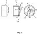
- three radially extending channels 14 are arranged on the inner bottom wall 24 of the pot bottom section 9.1 of the permanent magnet carrier 9 in the case of the exemplary embodiment shown, and the pot bottom section 9.1 has a hub 15 in which the motor shaft 11 is accommodated, being on the inner hub wall of the hub 15 in the case of the illustrated embodiment, three grooves 16 are introduced, which are fluidly connected to the channels 14 to form liquid overflow channels, such that the liquid located in the wet space N between one axial side of the permanent magnet carrier 9 and the other axial side of the permanent magnet carrier 9 can flow over.
- the channels 14 are aligned such that they extend outwards from the hub 15 in radial directions. In this case, the channels 14 are designed to run straight. As opposed to Fig. 6 are the channels 14 according to Fig. 5 However, they are aligned in such a way that they extend outwards from the hub 15. However, the channels 14 are in the case of execution according to Fig. 5 not designed to run straight, but to run curved.
- the curved course of the channels 14 can be according to Fig. 5 be such that in plan view, as in Fig. 5 is shown on the left, the channels extend as shown in this plane perpendicular to the axis of rotation and describe a curve or an arc in this plane.
- An arcuate course of the channels 14 can contribute to reducing noise during the rotation of the permanent magnet rotor 8.
- the pot bottom section 9.1 of the permanent magnet carrier 9 is, as shown, produced together with the circular cylinder wall section 9.2 of the permanent magnet carrier 9, for example by machining, by sintering, by casting, by deep drawing and/or deep pressing as a one-piece component.
- the pot bottom section 9.1 of the permanent magnet carrier 9 can also be manufactured together with the circular cylinder wall section 9.2 of the permanent magnet carrier 9 as a one-piece component by forming the circular cylinder wall section 9.2 from a tube section of a first semi-finished product and the pot bottom section 9.1 from a punched circular disk of a substantially plate-shaped second semi-finished product is formed, and the pipe section is connected to the circular disk by welding or soldering to form the one-piece component.
Landscapes
- Engineering & Computer Science (AREA)
- Power Engineering (AREA)
- Mechanical Engineering (AREA)
- General Engineering & Computer Science (AREA)
- Chemical & Material Sciences (AREA)
- Combustion & Propulsion (AREA)
- Structures Of Non-Positive Displacement Pumps (AREA)
- Connection Of Motors, Electrical Generators, Mechanical Devices, And The Like (AREA)
Claims (15)
- Pompe à rotor humide comprenant une roue de pompe (10) et un moteur d'entraînement électrique (3), le moteur d'entraînement électrique (3) comprenant un rotor à aimant permanent (8), qui comprend un arbre de moteur (11), sur lequel est fixé un support d'aimant permanent (9) du rotor à aimant permanent (8),dans laquelle une première section d'extrémité axiale (11.1) de l'arbre de moteur (11) comprend un logement pour une roue de pompe (10) et le support d'aimant permanent (9) supporte au moins un aimant permanent (13) et est fixé à une deuxième section d'extrémité axiale (11.2) de l'arbre de moteur (11) opposée à la première section d'extrémité (11.1) de l'arbre de moteur (11), etl'arbre de moteur (11) est monté à rotation au moyen d'un palier (12),caractérisée en ce que le support d'aimant permanent (9) est constitué selon une forme de pot, avec une section de fond de pot (9.1) fixée à la deuxième section d'extrémité axiale (11.2) de l'arbre de moteur (11) et s'étendant au moins essentiellement radialement par rapport à l'arbre de moteur (11) et une section de paroi cylindrique circulaire (9.2) directement contiguë au pourtour extérieur de la section de fond de pot (9.1), entourant l'arbre de moteur (11) de façon coaxiale, dans laquelle un écart entre les épaisseurs de paroi au niveau de la section de fond de pot et au niveau de la section de paroi cylindrique circulaire (9.2) va jusqu'à une double épaisseur de paroi ou la section de fond de pot (9.1) et la section de paroi cylindrique circulaire (9.2) ont une épaisseur de paroi exactement égale, etdans laquelle au moins un canal (14) s'étendant radialement est disposé sur une paroi de fond intérieure de la section de fond de pot (9.1) du support d'aimant permanent (9), et la section de fond de pot (9.1) comprend un moyeu (15), dans lequel l'arbre de moteur (11) est logé, et au moins une gorge (16) est incorporée sur la paroi intérieure de moyeu du moyeu (15), qui est reliée fluidiquement avec l'au moins un canal pour former un canal de trop-plein de fluide, de telle manière que le fluide se trouvant dans une chambre humide du moteur d'entraînement électrique de la pompe à rotor humide peut s'écouler entre un côté axial du support d'aimant permanent (9) et l'autre côté axial du support d'aimant permanent (9).
- Pompe à rotor humide comprenant une roue de pompe (10) et un moteur d'entraînement électrique (3) selon la revendication 1, caractérisée en ce qu'au moins la section de paroi cylindrique circulaire (9.2) du support d'aimant permanent (9) ou le support d'aimant permanent (9) entier incluant la section de fond de pot (9.1) et la section de paroi cylindrique circulaire (9.2) est fabriqué(e) en un matériau ferromagnétique.
- Pompe à rotor humide comprenant une roue de pompe (10) et un moteur d'entraînement électrique (3) selon la revendication 1, caractérisée en ce que la section de paroi cylindrique circulaire (9.2) du support d'aimant permanent (9), ou la section de fond de pot (9.1) du support d'aimant permanent (9), ou le support d'aimant permanent (9) entier incluant la section de fond de pot (9.1) et la section de paroi cylindrique circulaire (9.2) est fabriqué(e) en acier spécial, en particulier en un acier spécial magnétique, un matériau composite magnétique doux, un matériau magnétique fritté, et/ou un compound de matière plastique magnétique doux.
- Pompe à rotor humide comprenant une roue de pompe (10) et un moteur d'entraînement électrique (3) selon l'une des revendications 1 à 3, caractérisée en ce que l'au moins un aimant permanent (13) est fixé à une paroi d'enveloppe périphérique extérieure de la section de paroi cylindrique circulaire (9.2) du support d'aimant permanent (9) au moyen d'une liaison par collage.
- Pompe à rotor humide comprenant une roue de pompe (10) et un moteur d'entraînement électrique (3) selon la revendication 4, caractérisée en ce que le rotor à aimant permanent (8) comprend plusieurs aimants permanents individuels (13a) agencés de façon à être répartis régulièrement sur la périphérie, en particulier des aimants permanents en forme d'arcs de cercle (13b), qui sont fixés au moyen d'une liaison par collage à la paroi d'enveloppe périphérique extérieure de la section de paroi cylindrique circulaire (9.2) du support d'aimant permanent (9).
- Pompe à rotor humide comprenant une roue de pompe (10) et un moteur d'entraînement électrique (3) selon la revendication 4, caractérisée en ce que le rotor à aimant permanent (8) comprend un aimant permanent annulaire unique (13c) comprenant plusieurs paires de pôles magnétiques, qui est fixé par une liaison par collage à la paroi d'enveloppe périphérique extérieure de la section de paroi cylindrique circulaire (9.2) du support d'aimant permanent (9).
- Pompe à rotor humide comprenant une roue de pompe (10) et un moteur d'entraînement électrique (3) selon l'une des revendications 4 à 6, caractérisée en ce que l'au moins un aimant permanent (13) est fixé à la paroi d'enveloppe périphérique extérieure de la section de paroi cylindrique circulaire (9.2) du support d'aimant permanent (9) au moyen d'une liaison par collage, qui comprend une colle magnétiquement conductrice.
- Pompe à rotor humide comprenant une roue de pompe (10) et un moteur d'entraînement électrique (3) selon l'une des revendications 1 à 7, caractérisée en ce que la section de paroi cylindrique circulaire (9.2) du support d'aimant permanent (9) comprend une paroi d'enveloppe intérieure, qui entoure l'arbre de moteur (11) de façon coaxiale et délimite un espace creux (H) entre le support d'aimant permanent (9) et l'arbre de moteur (11), à l'intérieur duquel espace creux (H) un coussinet (20) du palier (12) s'étend.
- Pompe à rotor humide comprenant une roue de pompe (10) et un moteur d'entraînement électrique (3) selon la revendication 8, caractérisée en ce que la section de fond de pot (9.1) du support d'aimant permanent (9) comprend une paroi de fond intérieure, qui forme une surface de palier de butée, qui s'adosse directement contre une paroi d'extrémité du coussinet (20) du palier (12) pour supporter axialement l'arbre de moteur (11).
- Pompe à rotor humide comprenant une roue de pompe (10) et un moteur d'entraînement électrique (3) selon l'une des revendications 1 à 9, caractérisée en ce que la section de fond de pot (9.1) du support d'aimant permanent (9) est reliée à l'arbre de moteur (11) au moyen d'un assemblage à ajustement serti ou d'un assemblage soudé.
- Pompe à rotor humide comprenant une roue de pompe (10) et un moteur d'entraînement électrique (3) selon l'une des revendications 1 à 10, caractérisée en ce que la section de fond de pot (9.1) du support d'aimant permanent (9) est fabriquée ensemble avec la section de paroi cylindrique circulaire (9.2) du support d'aimants permanent (9) par usinage par enlèvement de copeaux, par frittage, par coulée, par emboutissage profond et/ou par pressage profond sous forme d'un composant monobloc.
- Pompe à rotor humide comprenant une roue de pompe (10) et un moteur d'entraînement électrique (3) selon l'une des revendications 1 à 10, caractérisée en ce que la section de fond de pot (9.1) du support d'aimant permanent (9) est fabriquée ensemble avec la section de paroi cylindrique circulaire (9.2) du support d'aimants permanent (9) sous forme d'un composant monobloc,
en formant la section de paroi cylindrique circulaire (9.2) à partir d'une section de tube d'un premier demi-produit et en formant la section de fond de pot (9.1) à partir d'un disque circulaire estampé d'un deuxième demi-produit essentiellement en forme de plaque, et en assemblant la section de tube avec le disque circulaire par soudage ou brasage pour former une pièce monobloc. - Pompe à rotor humide comprenant une roue de pompe (10) et un moteur d'entraînement électrique (3) selon l'une des revendications 1 à 12, comprenant une paroi de chambre de pompage (2a), qui délimite la chambre humide (N) de la pompe à rotor humide (1), dans laquelle la roue de pompe (10) est montée à rotation dans la chambre humide (N).
- Pompe à rotor humide comprenant une roue de pompe (10) et un moteur d'entraînement électrique (3) selon les revendications 9 et 13, caractérisée en ce que la paroi de chambre de pompage (2a) est configurée en forme de pot avec un fond de pot - de paroi de chambre de pompage (2b) et le fond de pot - de paroi de chambre de pompage (2b) comprend une surface de butée (A) tournée vers le côté frontal (T) de la deuxième section axiale (11.2) de l'arbre de moteur (11), qui est configurée pour supporter l'arbre de moteur (11) dans une direction opposée à une direction de palier de la surface de palier de butée (17) du palier (12).
- Appareil électroménager, en particulier lave-vaisselle ou machine à laver comprenant une pompe à rotor humide comprenant une roue de pompe (10) et un moteur d'entraînement électrique (3) selon l'une des revendications 1 à 14.
Applications Claiming Priority (2)
| Application Number | Priority Date | Filing Date | Title |
|---|---|---|---|
| DE102017223256.0A DE102017223256A1 (de) | 2017-12-19 | 2017-12-19 | Elektrischer Antriebsmotor, Nassläufer-Pumpe und Haushaltsgerät |
| PCT/EP2018/082829 WO2019120912A1 (fr) | 2017-12-19 | 2018-11-28 | Moteur d'entraînement électrique, pompe à rotor humide et appareil ménager |
Publications (2)
| Publication Number | Publication Date |
|---|---|
| EP3729605A1 EP3729605A1 (fr) | 2020-10-28 |
| EP3729605B1 true EP3729605B1 (fr) | 2023-11-08 |
Family
ID=64559686
Family Applications (1)
| Application Number | Title | Priority Date | Filing Date |
|---|---|---|---|
| EP18811512.5A Active EP3729605B1 (fr) | 2017-12-19 | 2018-11-28 | Pompe à rotor humide |
Country Status (6)
| Country | Link |
|---|---|
| US (1) | US12212187B2 (fr) |
| EP (1) | EP3729605B1 (fr) |
| CN (1) | CN111480282B (fr) |
| DE (1) | DE102017223256A1 (fr) |
| PL (1) | PL3729605T3 (fr) |
| WO (1) | WO2019120912A1 (fr) |
Families Citing this family (1)
| Publication number | Priority date | Publication date | Assignee | Title |
|---|---|---|---|---|
| EP3993228A1 (fr) | 2020-10-27 | 2022-05-04 | BSH Hausgeräte GmbH | Noyau de rotor, rotor à aimant permanent, moteur électrique et pompe électrique pour un appareil ménager |
Family Cites Families (25)
| Publication number | Priority date | Publication date | Assignee | Title |
|---|---|---|---|---|
| DE1638272B2 (de) * | 1968-03-02 | 1975-05-28 | Siemens Ag, 1000 Berlin Und 8000 Muenchen | Pumpe mit Spaltrohrmotor |
| JPH1113682A (ja) * | 1997-06-19 | 1999-01-19 | Japan Servo Co Ltd | Dcキャンドモータポンプ |
| DE19949082B4 (de) * | 1999-10-12 | 2006-03-02 | Ti Automotive (Neuss) Gmbh | Brennstoffpumpe für Brennkraftmaschinen |
| US20020158544A1 (en) * | 2001-04-26 | 2002-10-31 | Bobay Dennis P. | External rotor cup with annular flange extending therefrom |
| JP4774888B2 (ja) * | 2005-09-27 | 2011-09-14 | 日本電産株式会社 | モータ |
| DE102005052626A1 (de) * | 2005-11-02 | 2007-05-16 | Lsp Innovative Automotive Sys | Elektrischer Linearantrieb mit topfförmigem Läufer und innenliegenden Magnetelementen |
| JP4605202B2 (ja) | 2007-10-10 | 2011-01-05 | パナソニック電工株式会社 | モータ一体型ポンプのロータ部の製造方法 |
| CN101255868B (zh) | 2007-12-10 | 2010-11-24 | 兰州理工大学 | 电机内嵌叶片泵 |
| JP2011032923A (ja) * | 2009-07-31 | 2011-02-17 | Yamada Seisakusho Co Ltd | ウォータポンプ |
| NZ582764A (en) * | 2010-01-20 | 2012-04-27 | Wellington Drive Technologies Ltd | Rotor or stator with magnets contacting flux returns |
| DE102010019502B4 (de) * | 2010-05-06 | 2023-03-23 | Bühler Motor GmbH | Pumpe mit integriertem elektronisch kommutierten Gleichstrommotor |
| JP2012120395A (ja) | 2010-12-03 | 2012-06-21 | Denso Corp | モータ、および、これを用いた電動ポンプ |
| JP2014173585A (ja) | 2013-03-13 | 2014-09-22 | Hitachi Automotive Systems Ltd | 電動流体ポンプ |
| DE102014006568A1 (de) * | 2013-05-08 | 2014-11-13 | Ksb Aktiengesellschaft | Pumpenanordnung und Verfahren zum Herstellen eines Spalttopfes der Pumpenanordnung |
| DE102013211573A1 (de) | 2013-06-19 | 2014-12-24 | BSH Bosch und Siemens Hausgeräte GmbH | Pumpe mit einer Verdrehsicherung und Haushaltsgerät mit einer solchen Pumpe |
| CN105940235B (zh) * | 2014-01-10 | 2019-10-01 | 利滕斯汽车合伙公司 | 利用来自马达的磁力对离合装置进行控制 |
| EP2899855B1 (fr) * | 2014-01-23 | 2022-08-24 | Pierburg Pump Technology GmbH | Pompe de liquide de refroidissement électrique pour véhicule automobile |
| DE102014202572A1 (de) | 2014-02-12 | 2015-08-13 | BSH Hausgeräte GmbH | Elektrischer Antriebsmotor, Pumpe und Haushaltsgerät mit einer solchen Pumpe |
| DE102014207209A1 (de) * | 2014-04-15 | 2015-10-15 | Schaeffler Technologies AG & Co. KG | Wälzlager mit integriertem Klauenpolgenerator und Klauenpolgenerator |
| EP2977615A1 (fr) * | 2014-07-24 | 2016-01-27 | Aisin Seiki Kabushiki Kaisha | Pompe electrique |
| US9920764B2 (en) * | 2015-09-30 | 2018-03-20 | Peopleflo Manufacturing, Inc. | Pump devices |
| FR3043164B1 (fr) * | 2015-10-29 | 2018-04-13 | CRYODIRECT Limited | Pompe de transfert d'un gaz liquefie |
| CN109416058B (zh) * | 2016-07-04 | 2021-05-07 | 阿莫泰克有限公司 | 水泵 |
| CN206397719U (zh) | 2016-11-30 | 2017-08-11 | 深圳华星恒泰泵阀有限公司 | 一种可测流量的电磁水泵 |
| DE102017203736A1 (de) * | 2017-03-07 | 2018-09-13 | Mahle International Gmbh | Elektromotor |
-
2017
- 2017-12-19 DE DE102017223256.0A patent/DE102017223256A1/de not_active Withdrawn
-
2018
- 2018-11-28 WO PCT/EP2018/082829 patent/WO2019120912A1/fr not_active Ceased
- 2018-11-28 EP EP18811512.5A patent/EP3729605B1/fr active Active
- 2018-11-28 CN CN201880082034.6A patent/CN111480282B/zh active Active
- 2018-11-28 US US16/954,645 patent/US12212187B2/en active Active
- 2018-11-28 PL PL18811512.5T patent/PL3729605T3/pl unknown
Also Published As
| Publication number | Publication date |
|---|---|
| US20200313476A1 (en) | 2020-10-01 |
| WO2019120912A1 (fr) | 2019-06-27 |
| DE102017223256A1 (de) | 2019-06-19 |
| PL3729605T3 (pl) | 2024-03-11 |
| US12212187B2 (en) | 2025-01-28 |
| CN111480282A (zh) | 2020-07-31 |
| EP3729605A1 (fr) | 2020-10-28 |
| CN111480282B (zh) | 2022-07-08 |
Similar Documents
| Publication | Publication Date | Title |
|---|---|---|
| DE102011079226B4 (de) | Flüssigkeitspumpe, insbesondere Wasserpumpe | |
| DE60023782T2 (de) | Kleinstmotor und sein Herstellungsverfahren | |
| EP2457309B1 (fr) | Ensemble pour le découplage acoustique d'un stator d'un moteur électrique | |
| WO2018162282A1 (fr) | Moteur électrique | |
| EP2610497B1 (fr) | Groupe motopompe | |
| EP3105838B1 (fr) | Moteur d'entraînement électrique, pompe et appareil ménager équipé d'une telle pompe | |
| EP3610557B1 (fr) | Moteur d'entraînement électrique, pompe à rotor humide et appareil domestique, et procédé de fabrication d'un tel moteur à entraînement électrique | |
| DE68905377T2 (de) | Einstueckiger traeger und lagerschild-anordnung fuer elektrische motoren. | |
| DE102011079224B3 (de) | Kreiselpumpenlaufrad einer durch einen elektronisch kommutierten Gleichstrommotor angetriebenen Kreiselpumpe | |
| DE102008064132B4 (de) | Elektrische Maschine | |
| DE102016002832A1 (de) | Lüfter | |
| EP3729605B1 (fr) | Pompe à rotor humide | |
| EP3804093B1 (fr) | Moteur d'entraînement électrique, pompe à rotor noyé et appareil ménager | |
| EP1079112A2 (fr) | Pompe centrifuge entraínée par un moteur électrique à rotor extérieur | |
| EP1816729A2 (fr) | Moteur électrique | |
| DE102005032631B4 (de) | Fluiddynamisches Lagersystem | |
| DE102011079225A1 (de) | Flüssigkeitspumpe, insbesondere Wasserpumpe | |
| DE102017206089B4 (de) | Nassläufer-Pumpe und Haushaltsgerät | |
| DE102015014075B4 (de) | Spindelmotor zum Antrieb eines Lüfters | |
| EP4089284B1 (fr) | Pompe à rotor noyé | |
| DE102021115837A1 (de) | Elektromotor und Verfahren zum Herstellen eines Elektromotors | |
| DE102005062866A1 (de) | Elektrische Maschine mit Axialspielausgleich, sowie Herstellungsverfahren einer solchen | |
| DE102006005604B4 (de) | Fluiddynamisches Lagersystem | |
| DE102005044310B4 (de) | Spindelmotor mit einem Rotor und einem fluiddynamischen Lagersystem | |
| DE102019206548A1 (de) | Fluidpumpe |
Legal Events
| Date | Code | Title | Description |
|---|---|---|---|
| STAA | Information on the status of an ep patent application or granted ep patent |
Free format text: STATUS: UNKNOWN |
|
| STAA | Information on the status of an ep patent application or granted ep patent |
Free format text: STATUS: THE INTERNATIONAL PUBLICATION HAS BEEN MADE |
|
| PUAI | Public reference made under article 153(3) epc to a published international application that has entered the european phase |
Free format text: ORIGINAL CODE: 0009012 |
|
| STAA | Information on the status of an ep patent application or granted ep patent |
Free format text: STATUS: REQUEST FOR EXAMINATION WAS MADE |
|
| 17P | Request for examination filed |
Effective date: 20200720 |
|
| AK | Designated contracting states |
Kind code of ref document: A1 Designated state(s): AL AT BE BG CH CY CZ DE DK EE ES FI FR GB GR HR HU IE IS IT LI LT LU LV MC MK MT NL NO PL PT RO RS SE SI SK SM TR |
|
| AX | Request for extension of the european patent |
Extension state: BA ME |
|
| DAV | Request for validation of the european patent (deleted) | ||
| DAX | Request for extension of the european patent (deleted) | ||
| STAA | Information on the status of an ep patent application or granted ep patent |
Free format text: STATUS: EXAMINATION IS IN PROGRESS |
|
| 17Q | First examination report despatched |
Effective date: 20210722 |
|
| REG | Reference to a national code |
Ref country code: DE Ref legal event code: R079 Free format text: PREVIOUS MAIN CLASS: H02K0001270000 Ipc: F04D0013060000 Ref country code: DE Ref legal event code: R079 Ref document number: 502018013618 Country of ref document: DE Free format text: PREVIOUS MAIN CLASS: H02K0001270000 Ipc: F04D0013060000 |
|
| RIC1 | Information provided on ipc code assigned before grant |
Ipc: H02K 5/128 20060101ALI20230505BHEP Ipc: H02K 5/167 20060101ALI20230505BHEP Ipc: F04D 13/06 20060101AFI20230505BHEP |
|
| GRAP | Despatch of communication of intention to grant a patent |
Free format text: ORIGINAL CODE: EPIDOSNIGR1 |
|
| STAA | Information on the status of an ep patent application or granted ep patent |
Free format text: STATUS: GRANT OF PATENT IS INTENDED |
|
| INTG | Intention to grant announced |
Effective date: 20230627 |
|
| GRAS | Grant fee paid |
Free format text: ORIGINAL CODE: EPIDOSNIGR3 |
|
| P01 | Opt-out of the competence of the unified patent court (upc) registered |
Effective date: 20230828 |
|
| GRAA | (expected) grant |
Free format text: ORIGINAL CODE: 0009210 |
|
| STAA | Information on the status of an ep patent application or granted ep patent |
Free format text: STATUS: THE PATENT HAS BEEN GRANTED |
|
| AK | Designated contracting states |
Kind code of ref document: B1 Designated state(s): AL AT BE BG CH CY CZ DE DK EE ES FI FR GB GR HR HU IE IS IT LI LT LU LV MC MK MT NL NO PL PT RO RS SE SI SK SM TR |
|
| REG | Reference to a national code |
Ref country code: GB Ref legal event code: FG4D Free format text: NOT ENGLISH |
|
| REG | Reference to a national code |
Ref country code: CH Ref legal event code: EP |
|
| REG | Reference to a national code |
Ref country code: DE Ref legal event code: R096 Ref document number: 502018013618 Country of ref document: DE |
|
| REG | Reference to a national code |
Ref country code: IE Ref legal event code: FG4D Free format text: LANGUAGE OF EP DOCUMENT: GERMAN |
|
| REG | Reference to a national code |
Ref country code: LT Ref legal event code: MG9D |
|
| REG | Reference to a national code |
Ref country code: NL Ref legal event code: MP Effective date: 20231108 |
|
| PG25 | Lapsed in a contracting state [announced via postgrant information from national office to epo] |
Ref country code: GR Free format text: LAPSE BECAUSE OF FAILURE TO SUBMIT A TRANSLATION OF THE DESCRIPTION OR TO PAY THE FEE WITHIN THE PRESCRIBED TIME-LIMIT Effective date: 20240209 |
|
| PG25 | Lapsed in a contracting state [announced via postgrant information from national office to epo] |
Ref country code: IS Free format text: LAPSE BECAUSE OF FAILURE TO SUBMIT A TRANSLATION OF THE DESCRIPTION OR TO PAY THE FEE WITHIN THE PRESCRIBED TIME-LIMIT Effective date: 20240308 |
|
| PG25 | Lapsed in a contracting state [announced via postgrant information from national office to epo] |
Ref country code: LT Free format text: LAPSE BECAUSE OF FAILURE TO SUBMIT A TRANSLATION OF THE DESCRIPTION OR TO PAY THE FEE WITHIN THE PRESCRIBED TIME-LIMIT Effective date: 20231108 |
|
| PG25 | Lapsed in a contracting state [announced via postgrant information from national office to epo] |
Ref country code: NL Free format text: LAPSE BECAUSE OF FAILURE TO SUBMIT A TRANSLATION OF THE DESCRIPTION OR TO PAY THE FEE WITHIN THE PRESCRIBED TIME-LIMIT Effective date: 20231108 |
|
| PG25 | Lapsed in a contracting state [announced via postgrant information from national office to epo] |
Ref country code: ES Free format text: LAPSE BECAUSE OF FAILURE TO SUBMIT A TRANSLATION OF THE DESCRIPTION OR TO PAY THE FEE WITHIN THE PRESCRIBED TIME-LIMIT Effective date: 20231108 |
|
| PG25 | Lapsed in a contracting state [announced via postgrant information from national office to epo] |
Ref country code: NL Free format text: LAPSE BECAUSE OF FAILURE TO SUBMIT A TRANSLATION OF THE DESCRIPTION OR TO PAY THE FEE WITHIN THE PRESCRIBED TIME-LIMIT Effective date: 20231108 Ref country code: LT Free format text: LAPSE BECAUSE OF FAILURE TO SUBMIT A TRANSLATION OF THE DESCRIPTION OR TO PAY THE FEE WITHIN THE PRESCRIBED TIME-LIMIT Effective date: 20231108 Ref country code: IS Free format text: LAPSE BECAUSE OF FAILURE TO SUBMIT A TRANSLATION OF THE DESCRIPTION OR TO PAY THE FEE WITHIN THE PRESCRIBED TIME-LIMIT Effective date: 20240308 Ref country code: GR Free format text: LAPSE BECAUSE OF FAILURE TO SUBMIT A TRANSLATION OF THE DESCRIPTION OR TO PAY THE FEE WITHIN THE PRESCRIBED TIME-LIMIT Effective date: 20240209 Ref country code: ES Free format text: LAPSE BECAUSE OF FAILURE TO SUBMIT A TRANSLATION OF THE DESCRIPTION OR TO PAY THE FEE WITHIN THE PRESCRIBED TIME-LIMIT Effective date: 20231108 Ref country code: BG Free format text: LAPSE BECAUSE OF FAILURE TO SUBMIT A TRANSLATION OF THE DESCRIPTION OR TO PAY THE FEE WITHIN THE PRESCRIBED TIME-LIMIT Effective date: 20240208 Ref country code: PT Free format text: LAPSE BECAUSE OF FAILURE TO SUBMIT A TRANSLATION OF THE DESCRIPTION OR TO PAY THE FEE WITHIN THE PRESCRIBED TIME-LIMIT Effective date: 20240308 |
|
| PG25 | Lapsed in a contracting state [announced via postgrant information from national office to epo] |
Ref country code: SE Free format text: LAPSE BECAUSE OF FAILURE TO SUBMIT A TRANSLATION OF THE DESCRIPTION OR TO PAY THE FEE WITHIN THE PRESCRIBED TIME-LIMIT Effective date: 20231108 Ref country code: RS Free format text: LAPSE BECAUSE OF FAILURE TO SUBMIT A TRANSLATION OF THE DESCRIPTION OR TO PAY THE FEE WITHIN THE PRESCRIBED TIME-LIMIT Effective date: 20231108 Ref country code: NO Free format text: LAPSE BECAUSE OF FAILURE TO SUBMIT A TRANSLATION OF THE DESCRIPTION OR TO PAY THE FEE WITHIN THE PRESCRIBED TIME-LIMIT Effective date: 20240208 Ref country code: LV Free format text: LAPSE BECAUSE OF FAILURE TO SUBMIT A TRANSLATION OF THE DESCRIPTION OR TO PAY THE FEE WITHIN THE PRESCRIBED TIME-LIMIT Effective date: 20231108 Ref country code: HR Free format text: LAPSE BECAUSE OF FAILURE TO SUBMIT A TRANSLATION OF THE DESCRIPTION OR TO PAY THE FEE WITHIN THE PRESCRIBED TIME-LIMIT Effective date: 20231108 |
|
| REG | Reference to a national code |
Ref country code: CH Ref legal event code: PL |
|
| PG25 | Lapsed in a contracting state [announced via postgrant information from national office to epo] |
Ref country code: DK Free format text: LAPSE BECAUSE OF FAILURE TO SUBMIT A TRANSLATION OF THE DESCRIPTION OR TO PAY THE FEE WITHIN THE PRESCRIBED TIME-LIMIT Effective date: 20231108 |
|
| PG25 | Lapsed in a contracting state [announced via postgrant information from national office to epo] |
Ref country code: LU Free format text: LAPSE BECAUSE OF NON-PAYMENT OF DUE FEES Effective date: 20231128 |
|
| PG25 | Lapsed in a contracting state [announced via postgrant information from national office to epo] |
Ref country code: CH Free format text: LAPSE BECAUSE OF NON-PAYMENT OF DUE FEES Effective date: 20231130 |
|
| PG25 | Lapsed in a contracting state [announced via postgrant information from national office to epo] |
Ref country code: SK Free format text: LAPSE BECAUSE OF FAILURE TO SUBMIT A TRANSLATION OF THE DESCRIPTION OR TO PAY THE FEE WITHIN THE PRESCRIBED TIME-LIMIT Effective date: 20231108 |
|
| PG25 | Lapsed in a contracting state [announced via postgrant information from national office to epo] |
Ref country code: SM Free format text: LAPSE BECAUSE OF FAILURE TO SUBMIT A TRANSLATION OF THE DESCRIPTION OR TO PAY THE FEE WITHIN THE PRESCRIBED TIME-LIMIT Effective date: 20231108 Ref country code: SK Free format text: LAPSE BECAUSE OF FAILURE TO SUBMIT A TRANSLATION OF THE DESCRIPTION OR TO PAY THE FEE WITHIN THE PRESCRIBED TIME-LIMIT Effective date: 20231108 Ref country code: RO Free format text: LAPSE BECAUSE OF FAILURE TO SUBMIT A TRANSLATION OF THE DESCRIPTION OR TO PAY THE FEE WITHIN THE PRESCRIBED TIME-LIMIT Effective date: 20231108 Ref country code: LU Free format text: LAPSE BECAUSE OF NON-PAYMENT OF DUE FEES Effective date: 20231128 Ref country code: IT Free format text: LAPSE BECAUSE OF FAILURE TO SUBMIT A TRANSLATION OF THE DESCRIPTION OR TO PAY THE FEE WITHIN THE PRESCRIBED TIME-LIMIT Effective date: 20231108 Ref country code: EE Free format text: LAPSE BECAUSE OF FAILURE TO SUBMIT A TRANSLATION OF THE DESCRIPTION OR TO PAY THE FEE WITHIN THE PRESCRIBED TIME-LIMIT Effective date: 20231108 Ref country code: DK Free format text: LAPSE BECAUSE OF FAILURE TO SUBMIT A TRANSLATION OF THE DESCRIPTION OR TO PAY THE FEE WITHIN THE PRESCRIBED TIME-LIMIT Effective date: 20231108 Ref country code: CH Free format text: LAPSE BECAUSE OF NON-PAYMENT OF DUE FEES Effective date: 20231130 |
|
| REG | Reference to a national code |
Ref country code: BE Ref legal event code: MM Effective date: 20231130 |
|
| REG | Reference to a national code |
Ref country code: DE Ref legal event code: R097 Ref document number: 502018013618 Country of ref document: DE |
|
| PG25 | Lapsed in a contracting state [announced via postgrant information from national office to epo] |
Ref country code: MC Free format text: LAPSE BECAUSE OF FAILURE TO SUBMIT A TRANSLATION OF THE DESCRIPTION OR TO PAY THE FEE WITHIN THE PRESCRIBED TIME-LIMIT Effective date: 20231108 |
|
| PG25 | Lapsed in a contracting state [announced via postgrant information from national office to epo] |
Ref country code: MC Free format text: LAPSE BECAUSE OF FAILURE TO SUBMIT A TRANSLATION OF THE DESCRIPTION OR TO PAY THE FEE WITHIN THE PRESCRIBED TIME-LIMIT Effective date: 20231108 |
|
| REG | Reference to a national code |
Ref country code: IE Ref legal event code: MM4A |
|
| PLBE | No opposition filed within time limit |
Free format text: ORIGINAL CODE: 0009261 |
|
| STAA | Information on the status of an ep patent application or granted ep patent |
Free format text: STATUS: NO OPPOSITION FILED WITHIN TIME LIMIT |
|
| PG25 | Lapsed in a contracting state [announced via postgrant information from national office to epo] |
Ref country code: IE Free format text: LAPSE BECAUSE OF NON-PAYMENT OF DUE FEES Effective date: 20231128 |
|
| PG25 | Lapsed in a contracting state [announced via postgrant information from national office to epo] |
Ref country code: BE Free format text: LAPSE BECAUSE OF NON-PAYMENT OF DUE FEES Effective date: 20231130 |
|
| 26N | No opposition filed |
Effective date: 20240809 |
|
| PG25 | Lapsed in a contracting state [announced via postgrant information from national office to epo] |
Ref country code: SI Free format text: LAPSE BECAUSE OF FAILURE TO SUBMIT A TRANSLATION OF THE DESCRIPTION OR TO PAY THE FEE WITHIN THE PRESCRIBED TIME-LIMIT Effective date: 20231108 |
|
| PG25 | Lapsed in a contracting state [announced via postgrant information from national office to epo] |
Ref country code: SI Free format text: LAPSE BECAUSE OF FAILURE TO SUBMIT A TRANSLATION OF THE DESCRIPTION OR TO PAY THE FEE WITHIN THE PRESCRIBED TIME-LIMIT Effective date: 20231108 Ref country code: IE Free format text: LAPSE BECAUSE OF NON-PAYMENT OF DUE FEES Effective date: 20231128 Ref country code: BE Free format text: LAPSE BECAUSE OF NON-PAYMENT OF DUE FEES Effective date: 20231130 |
|
| REG | Reference to a national code |
Ref country code: AT Ref legal event code: MM01 Ref document number: 1629832 Country of ref document: AT Kind code of ref document: T Effective date: 20231128 |
|
| PG25 | Lapsed in a contracting state [announced via postgrant information from national office to epo] |
Ref country code: AT Free format text: LAPSE BECAUSE OF NON-PAYMENT OF DUE FEES Effective date: 20231128 |
|
| PG25 | Lapsed in a contracting state [announced via postgrant information from national office to epo] |
Ref country code: AT Free format text: LAPSE BECAUSE OF NON-PAYMENT OF DUE FEES Effective date: 20231128 |
|
| PG25 | Lapsed in a contracting state [announced via postgrant information from national office to epo] |
Ref country code: FI Free format text: LAPSE BECAUSE OF FAILURE TO SUBMIT A TRANSLATION OF THE DESCRIPTION OR TO PAY THE FEE WITHIN THE PRESCRIBED TIME-LIMIT Effective date: 20231108 |
|
| PG25 | Lapsed in a contracting state [announced via postgrant information from national office to epo] |
Ref country code: CY Free format text: LAPSE BECAUSE OF FAILURE TO SUBMIT A TRANSLATION OF THE DESCRIPTION OR TO PAY THE FEE WITHIN THE PRESCRIBED TIME-LIMIT; INVALID AB INITIO Effective date: 20181128 |
|
| PG25 | Lapsed in a contracting state [announced via postgrant information from national office to epo] |
Ref country code: HU Free format text: LAPSE BECAUSE OF FAILURE TO SUBMIT A TRANSLATION OF THE DESCRIPTION OR TO PAY THE FEE WITHIN THE PRESCRIBED TIME-LIMIT; INVALID AB INITIO Effective date: 20181128 |
|
| PGFP | Annual fee paid to national office [announced via postgrant information from national office to epo] |
Ref country code: DE Payment date: 20251130 Year of fee payment: 8 |
|
| PGFP | Annual fee paid to national office [announced via postgrant information from national office to epo] |
Ref country code: GB Payment date: 20251120 Year of fee payment: 8 |
|
| PGFP | Annual fee paid to national office [announced via postgrant information from national office to epo] |
Ref country code: FR Payment date: 20251125 Year of fee payment: 8 |
|
| PGFP | Annual fee paid to national office [announced via postgrant information from national office to epo] |
Ref country code: TR Payment date: 20251124 Year of fee payment: 8 |
|
| PGFP | Annual fee paid to national office [announced via postgrant information from national office to epo] |
Ref country code: CZ Payment date: 20251118 Year of fee payment: 8 |
|
| PGFP | Annual fee paid to national office [announced via postgrant information from national office to epo] |
Ref country code: PL Payment date: 20251117 Year of fee payment: 8 |