EP3729953B1 - Schneidvorrichtung - Google Patents
Schneidvorrichtung Download PDFInfo
- Publication number
- EP3729953B1 EP3729953B1 EP20000118.8A EP20000118A EP3729953B1 EP 3729953 B1 EP3729953 B1 EP 3729953B1 EP 20000118 A EP20000118 A EP 20000118A EP 3729953 B1 EP3729953 B1 EP 3729953B1
- Authority
- EP
- European Patent Office
- Prior art keywords
- cutting
- switching
- coupling
- switching shaft
- cutting device
- Prior art date
- Legal status (The legal status is an assumption and is not a legal conclusion. Google has not performed a legal analysis and makes no representation as to the accuracy of the status listed.)
- Active
Links
Images




Classifications
-
- B—PERFORMING OPERATIONS; TRANSPORTING
- B26—HAND CUTTING TOOLS; CUTTING; SEVERING
- B26D—CUTTING; DETAILS COMMON TO MACHINES FOR PERFORATING, PUNCHING, CUTTING-OUT, STAMPING-OUT OR SEVERING
- B26D5/00—Arrangements for operating and controlling machines or devices for cutting, cutting-out, stamping-out, punching, perforating, or severing by means other than cutting
-
- A—HUMAN NECESSITIES
- A01—AGRICULTURE; FORESTRY; ANIMAL HUSBANDRY; HUNTING; TRAPPING; FISHING
- A01D—HARVESTING; MOWING
- A01D90/00—Vehicles for carrying harvested crops with means for selfloading or unloading
- A01D90/02—Loading means
- A01D90/04—Loading means with additional cutting means
- A01D90/06—Loading means with additional cutting means with chaff cutters, i.e. choppers used as loading and cutting means
-
- A—HUMAN NECESSITIES
- A01—AGRICULTURE; FORESTRY; ANIMAL HUSBANDRY; HUNTING; TRAPPING; FISHING
- A01F—PROCESSING OF HARVESTED PRODUCE; HAY OR STRAW PRESSES; DEVICES FOR STORING AGRICULTURAL OR HORTICULTURAL PRODUCE
- A01F15/00—Baling presses for straw, hay or the like
- A01F15/08—Details
- A01F15/10—Feeding devices for the crop material e.g. precompression devices
-
- B—PERFORMING OPERATIONS; TRANSPORTING
- B26—HAND CUTTING TOOLS; CUTTING; SEVERING
- B26D—CUTTING; DETAILS COMMON TO MACHINES FOR PERFORATING, PUNCHING, CUTTING-OUT, STAMPING-OUT OR SEVERING
- B26D5/00—Arrangements for operating and controlling machines or devices for cutting, cutting-out, stamping-out, punching, perforating, or severing by means other than cutting
- B26D5/02—Means for moving the cutting member into its operative position for cutting
-
- A—HUMAN NECESSITIES
- A01—AGRICULTURE; FORESTRY; ANIMAL HUSBANDRY; HUNTING; TRAPPING; FISHING
- A01F—PROCESSING OF HARVESTED PRODUCE; HAY OR STRAW PRESSES; DEVICES FOR STORING AGRICULTURAL OR HORTICULTURAL PRODUCE
- A01F15/00—Baling presses for straw, hay or the like
- A01F15/08—Details
- A01F15/10—Feeding devices for the crop material e.g. precompression devices
- A01F2015/107—Means for withdrawing knives, rotor or walls of the feeding chamber in case of plugging or congestion
-
- A—HUMAN NECESSITIES
- A01—AGRICULTURE; FORESTRY; ANIMAL HUSBANDRY; HUNTING; TRAPPING; FISHING
- A01F—PROCESSING OF HARVESTED PRODUCE; HAY OR STRAW PRESSES; DEVICES FOR STORING AGRICULTURAL OR HORTICULTURAL PRODUCE
- A01F15/00—Baling presses for straw, hay or the like
- A01F15/08—Details
- A01F15/10—Feeding devices for the crop material e.g. precompression devices
- A01F2015/108—Cutting devices comprising cutter and counter-cutter
Definitions
- the invention relates to a cutting device for conveying and cutting, in particular, agricultural material to be cut.
- the cutting device has a conveying channel and at least one pivotably mounted cutting element.
- the cutting element can be moved from a rest position into a cutting position by moving it in a first pivoting direction. In the cutting position, the cutting element for cutting the material to be cut is at least partially positioned within the conveying channel.
- the cutting device has an actuating device which comprises an actuating element which, at least in the cutting position of the cutting element, rests on the cutting element during operation and is in particular mounted so as to be pivotable about an actuating pivot axis.
- the cutting device has a shift shaft which can be converted into different shift positions and is rotatably mounted about a shift shaft axis. With the Shift shaft, the actuating element is coupled in at least one of the shift positions of the shift shaft.
- the cutting device has a restoring element for returning the cutting element into the cutting position and for holding the cutting element in the cutting position.
- an agricultural harvesting machine is known with a cutting device as described above. Due to the possibility of transferring the cutting element from the rest position into the cutting position, a cut length of the material to be cut can be set.
- the selector shaft makes it possible to choose whether the cutting element should be positioned in the rest or in the cutting position during operation, or which cutting elements of a plurality of cutting elements should be positioned in the rest or in the cutting position during operation.
- the object of the present invention is to provide a cutting device of the generic type with a smaller space requirement and the greatest possible operational reliability.
- the object is achieved in that the actuating element has a switching contact area which is in contact with the switching shaft in one switching position during operation.
- the actuating element is coupled to it at least in the one switching position of the switching shaft by being in direct contact with the switching shaft.
- the conveyor channel of the cutting device is delimited in particular by a conveyor channel wall.
- the conveying channel wall has in particular slot-shaped recesses through which the cutting element extends in particular at least in the cutting position.
- the conveyor channel is in particular delimited by a conveyor and cutting rotor.
- the cutting element In the rest position, the cutting element is not or only to a small extent arranged within the conveying channel. In contrast, in the cutting position of the cutting element, a larger proportion, in particular a cutting edge of the cutting element, is arranged in the conveying channel.
- the cutting element is preferably pivoted upwards from the rest position into the operating position.
- the adjusting element which is in contact with the cutting element at least during operation, acts on the cutting element with a force.
- This force is at least partially provided by the restoring element, which is in particular arranged directly on the actuating element.
- the cutting element is firstly guided into the cutting position and secondly held therein.
- the force for holding the cutting element in the cutting position is so great during operation that reliable cutting of the material to be cut moving through the conveying channel is possible.
- the force is so small that if there is a foreign body such as a stone in the material to be cut, the cutting element can move away from the foreign body, i.e. can pivot back against the force applied by the adjusting element. If the foreign body has then passed through the conveying channel, the cutting element is returned to the cutting position by the adjusting device and the restoring element.
- the switching shaft can be used, in particular, to set the position in which the cutting element should be in the subsequent operation between two operating phases. In each of its possible switching positions, the switching shaft defines whether the cutting element should be in the cutting position or in the rest position.
- the switching shaft is designed such that the actuating element rests against the switching shaft when the cutting device is in operation, either in the cutting position or in the rest position.
- the selector shaft has, in particular, different geometries along its circumference, through which the position of the cutting element is ultimately predefined.
- the cutting device is in operation when material to be cut is conveyed through the conveying channel and, if necessary, cut by the cutting element.
- the actuating element is designed to rest against the cutting element as well as to rest against the selector shaft, there are further components for power transmission between the selector shaft and the actuating element is no longer necessary. As a result, the installation space of the cutting device is minimized and the number of components necessary for its functioning is reduced to a minimum. As a result, downtimes of the cutting device can be significantly reduced.
- the switching shaft axis runs in particular transversely to the conveying direction of the crop in the conveying channel.
- the selector shaft is designed in particular to adjust a plurality of adjusting elements and thus cutting elements.
- the selector shaft preferably has a selector shaft body extending through in the direction of the selector shaft axis as well as a plurality of selector shaft attachments adjoining one another in the direction of the selector shaft axis, which are designed at least in one switch position to rest on the switch contact area of the actuating element.
- the adjusting element is preferably mounted so as to be pivotable about the adjusting pivot axis.
- the switching contact area is particularly preferably encompassed by a first leg of the actuating element.
- the first leg extends away from the setting pivot axis and away from the cutting element.
- the adjusting element consists of two legs that are rigid with respect to one another and each extend essentially radially away from the adjusting pivot axis. Due to the arrangement of the switching contact area on the leg facing away from the cutting element, the adjusting device can be set up easily despite the multiple function of the adjusting element and component collisions can be avoided. In particular, a larger radial extension of the adjusting element from the adjusting pivot axis, which with the arrangement of the switching contact area on the Cutting element facing legs would necessarily be avoided.
- the switching contact area preferably has a recess into which a switching element of the switching shaft extends in the switching position during operation.
- the switching element is in particular a cam, preferably comprised by a switching shaft attachment, which extends radially away from the switching shaft axis.
- the actuating element preferably has at least one pin which, in the switching position, extends into a recess in the switching shaft during operation. The pairing of recess and switching element / pin enables reliable engagement of the switching shaft and actuating element in one another in the switching position and thus preventing the switching position from being left unintentionally.
- the resetting element presses, in particular, the actuating element against the switching shaft, in particular against the switching element.
- the cutting device has a coupling element which is designed to release the actuating element from the switching shaft.
- the coupling element rests in a coupling position on a coupling contact area of the actuating element.
- the coupling element ensures that essentially no torque has to be overcome in order to transfer the shift shaft into another shift position, which torque resulted from the actuating element resting against the shift shaft. Instead, the coupling element separates the actuating element from the switching element before the switching shaft moves into another switching position is convicted. This results in lower component loads and thus fewer downtimes.
- the coupling element is in particular pivotably mounted. When it is moved into the coupling position, it preferably rests against the coupling contact area of the actuating element.
- the coupling contact area is particularly preferably at a greater distance from the adjusting pivot axis than the switching contact area.
- the coupling contact area is preferably part of the first leg of the adjusting element.
- the actuating element is preferably released by moving the coupling element into the coupling position both from the switching shaft and from the cutting element.
- the coupling element counteracts the restoring element with regard to the pivoting direction of the adjusting element.
- the restoring element ensures, in particular after the coupling element has been transferred back from the coupling position, that the actuating element is in contact with the cutting element and / or the selector shaft.
- the coupling element is preferably mounted so as to be pivotable, in particular, about the stationary adjusting pivot axis. Due to the type of storage, the coupling function can be implemented particularly reliably. In that the adjusting element and the coupling element are arranged pivotably about the same axis, the cutting device is also particularly compact and when the coupling element is transferred into the coupling position, friction between the coupling and adjusting element is avoided.
- a coupling return element which returns the coupling element from the coupling position is preferably arranged on the coupling element.
- the coupling return element is designed in particular as a tension spring.
- a single-acting hydraulic cylinder is arranged on the coupling element, by means of which the coupling element can preferably be transferred into the coupling position.
- the restoring element is preferably arranged on a second leg of the actuating element. In the cutting position of the cutting element, the second leg extends from the adjusting pivot axis to the cutting element.
- the restoring element is designed in particular as a tension spring.
- One end of the restoring element is preferably arranged in a stationary manner on the machine frame.
- the restoring element extends at least partially behind the cutting element, at least in the cutting position of the cutting element and viewed in a side view or in a longitudinal section of the cutting device.
- the restoring element is arranged in a particularly space-saving manner.
- the restoring force acts at least essentially in the radial direction on the adjusting element.
- the restoring force of the restoring element is introduced into the area in the adjusting element with which the adjusting element is also in contact with the cutting element.
- the actuating device is designed in such a way that the cutting element is arranged in the rest position during operation and when the switching contact area is in contact with the switching shaft.
- the actuating element rests either on the cutting element or on the selector shaft during operation. This avoids extreme component loads that were associated with simultaneous contact with both the cutting element and the selector shaft.
- the cutting device preferably has a drive device for continuous rotation of the selector shaft by more than 360 °.
- the drive device has a hydraulic motor, an electric motor or a pneumatically operated motor.
- the drive device enables uninterrupted rotation at, in particular, constant rotational speed, with no manual force having to be introduced by an operator for this purpose.
- the drive device is designed for continuous, multiple and uninterrupted rotation of the selector shaft. It is also possible to start the rotation quickly and then slow it down and vice versa. In addition to its switching function, a cleaning function can be achieved by the switching shaft through the drive device.
- the drive device comprises an angle sensor. This allows the drive device to automatically move to any preselected switch positions without having to interrupt the continuous rotation.
- the cutting device preferably has a locking device which is designed to lock the drive device when the switching contact area is in contact with the switching shaft, in particular when the coupling element is not arranged in the coupling position.
- the locking device comprises in particular a sensor for determining the position of the adjusting element or the coupling element.
- the drive device is particularly preferably designed to provide a switching shaft rotation speed in a range from 10 to 80 revolutions per minute. Due to these rotational speeds of the selector shaft, agricultural cuttings deposits such as hay or straw deposits can be conveyed out in a particularly effective manner, thereby enabling optimal protection of the cutting device components in this area of activity.
- the drive device preferably has a gear for reducing a drive speed that deviates from a shift shaft speed, in particular of the hydraulic motor or an alternative electric motor.
- the transmission comprises a pair of spur gears, by means of which the drive speed with its transmission to the shift shaft is reduced to the shift shaft speed.
- the transmission enables drive motors with sufficient drive power to be used, the installation space of which is small due to a large speed-torque ratio.
- a radial extension of the shift element from the shift shaft axis is preferably at least 1.3 times, in particular at least 1.5 times as large as the radial extension of an at least essentially cylindrical section of the shift shaft from the shift shaft axis.
- the shift shaft has a plurality of shift elements which are spaced apart from one another in the direction of the shift shaft axis and are each assigned to a cutting element.
- the essentially cylindrical section of the shift shaft is located between two of these shift shaft elements. Due to the significantly larger radius of the switching elements compared to this section, they achieve a particularly large conveying function and thus ensure quick cleaning of the cutting device.
- the shift shaft particularly preferably has at least one, in particular, elastic conveying element between two shift elements spaced apart from one another in the direction of the shift shaft axis.
- the conveying element is arranged between the switching elements to the extent that it is arranged on an axial switching shaft section which is arranged between the axial switching shaft sections with the switching elements.
- the conveying element is designed in particular as a brush, a rigid driver or a similar attachment.
- the radial extension of the conveying element from the shift shaft axis is in particular greater than the radial extension of the shift elements from the shift shaft axis.
- the conveying function is further increased by this large radius and, in particular, the deposits of items to be cut which are arranged between two adjusting elements or between two cutting elements can also be conveyed out.
- the cutting device has at least one cleaning element which is coupled to the switching shaft and rotating depending on its rotation, the cleaning rotation axis of which is arranged in particular parallel to the switching shaft axis.
- the cleaning element is coupled to the selector shaft in particular via a pair of spur gears and is preferred also driven by the drive device. With the separate cleaning element, areas of the cutting device that are further apart from the selector shaft can also be automatically cleaned.
- the object is also achieved by an agricultural machine with a cutting device according to one of the preceding claims.
- the agricultural machine is preferably a baling press or a loading wagon, by means of which, during operation, in particular hay or straw can be picked up and cut directly from the ground.
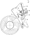
- the Figs. 1 to 3 show a cutting device 2 according to the invention in a longitudinal section.
- the cutting device 2 forms a conveying channel 4 through which, during operation, in particular agricultural material to be cut is conveyed and in particular cut.
- the conveying channel 4 is delimited by a conveying and cutting rotor 54 on the one hand and a conveying channel wall 56 on the other hand.
- the cutting device 2 has a plurality of pivotably mounted cutting elements 6 (see also Fig. 4 ), of which in the Figs. 1 to 3 each one is shown.
- the cutting element 6 is moved in a first pivoting direction 8 from a rest position (cf. Fig. 3 ) into a cutting position (cf. Fig. 1 ) transferable. In the cutting position, the cutting element 6 is positioned in the conveying channel 4 for cutting the material to be cut with a cutting edge.
- the cutting device 2 has an adjusting device (I) for returning the cutting element 6 into the cutting position and for holding the cutting element 6 in the cutting position.
- the adjusting device (I) comprises an adjusting element 22 and a restoring element 10.
- the adjusting element 22 is mounted pivotably about an adjusting pivot axis 36.
- the restoring element 10 is fixedly arranged at one end on a machine frame and at the other end on a second leg 44 of the adjusting element 22.
- the adjusting element 22 rests with a roller on a first surface section 18 of the cutting element 6.
- a tensile force of the restoring element 10 pulls the adjusting element 22 into a recess in the cutting element 6, whereby the cutting element 6 remains in the cutting position as far as possible during operation.
- the actuating element 22 is moved from its in Fig. 3 position shown applied to the first surface section 18.
- a first torque is applied to the cutting element 6 in the pivoting direction 8.
- the cutting element can be released regularly from the rest position and slides upwards and along the adjusting element 22. Due to the convergence of the second leg 44 of the adjusting element 22 to the pivot axis of the cutting element 6 and the associated shortening of the restoring element 10, the torque applied to the cutting element 6 decreases with the upward pivoting of the cutting element 6, starting from the first torque.
- the adjusting device (I) enables the cutting element 6 to be pivoted back from the cutting position against the tensile force of the restoring element 10. After the foreign body has passed, the restoring element 10 causes the cutting element to be reset 6 in the cutting position.
- a coupling element 26 and the switching shaft 28 serve to transfer the cutting element 6 from the cutting position to the rest position.
- the coupling element 26 can first be pivoted against a coupling contact area 40 of the actuating element 22 (cf. Fig. 2 ). This pivoting is possible in particular with a hydraulic cylinder 24 coupled to the coupling element (cf. Fig. 5 ) bring about.
- the coupling contact area 40 is arranged on a first leg 34 of the actuating element 22.
- the coupling position shown is the adjusting element 22 both of the cutting element 6 and of the shift shaft 28 spaced apart.
- the shift shaft 28 is rotatably mounted about a shift shaft axis 58 and comprises a plurality of shift elements 38 along its circumference.
- the shift shaft 28 is shown in FIG Fig. 1 a first switching position for positioning the cutting element 6 in the cutting position.
- the switching shaft 28 can be pivoted through ⁇ 360 ° into further switching positions such as, for example, in FIG Fig. 2 transferable.
- a switching element 38 for positioning the cutting element 6 in the rest position faces the switching contact area 32, contrary to the first switching positions.
- the coupling element 26 can be moved out of the coupling position (cf. Fig. 2 ) into a release position (cf. Fig. 3 ) transfer back from a coupling restoring element 42.
- the actuating element 22 follows the movement of the coupling element 26 until the actuating element 22 rests with a switch contact area on one of the switching elements 38 of the switching shaft 28.
- the switching contact area 32 is arranged on the first leg 34 of the actuating element 22.
- the switch contact area 32 has a recess into which the one switch element 38 partially extends in the further switch position and after the coupling element 26 has been released (cf. Fig. 3 ). This avoids contact between the cutting element 6 and the adjusting element 22, as a result of which the cutting element 6 remains in the rest position.
- a transfer of the switching shaft 28 from the further switching position into a first switching position can be brought about in an analogous manner.
- a second adjusting element 16 of a second adjusting device (II) is rigidly connected to the coupling element 26.
- the second adjusting element 16 like the coupling element 26, can thus be pivoted about the adjusting pivot axis 36.
- the second setting element 16 is to be brought into contact with a second surface section 20 of the cutting element 6.
- the second setting element 16 is used to pivot the cutting element 6 from the rest position into the first pivoting direction 8.
- the second setting element 16 is designed to apply a second torque to the cutting element 6 in the rest position, the second torque being greater than that of the setting device (I) first torque to be applied to the cutting element 6 in the rest position.
- the second torque is so great that the cutting element 6 can be reliably pivoted from the rest position into the first pivoting direction 8 even if there are deposits of material to be cut between the cutting element 6 and the conveying channel wall 56, if such pivoting can no longer be achieved due to the smaller first torque is.
- the second setting element 16 extends below a plurality of cutting elements 6 (cf. Fig. 5 ).
- An adjusting device (I), each with an adjusting element 22, is assigned to each cutting element 6.
- the coupling element 26, like the second actuating element 16, has a width that essentially corresponds to a width of the conveying channel 4, whereby all actuating elements 22 can be released from the respective cutting element 6 as well as from the switching shaft 28 by the coupling element 26.
- the cutting device 2 has a drive device having a hydraulic motor 46 for continuous rotation of the selector shaft 28 by more than 360 ° (cf. Fig. 4 and 5 ).
- the cutting device 2 has a locking device, not shown, for locking the drive device when the switching contact area 32 is in contact with the switching shaft 28, in particular when the coupling element 26 is not arranged in the coupling position.
- the hydraulic motor 46 is coupled to the shift shaft 28 via a gear (not shown) to reduce its drive speed.
- the drive device for the automatic setting of different switching positions of the switching shaft 28 is designed by an angle sensor.
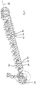
- the shift elements 38 of the shift shaft 28 have a radial extension from the shift shaft axis 58 which is more than 1.3 times as large as the radial extension of a cylindrical section 50 of the shift shaft 28 from the shift shaft axis 58 (cf. Fig. 6 ). Between two adjacent shift elements 38 in the direction of the shift shaft axis 58, the shift shaft 28 has, in particular, a conveying element 52.
- Fig. 6 shows exemplary conveying elements 52 only on a section of the switching shaft 28. Such conveying elements 52 are preferably arranged along the entire switching shaft length on the switching shaft 28.
- Fig. 7 shows a baling press 30 with a cutting device 2 according to the invention.
- the baling press 30 is moved in a direction of travel 60 and in the process agricultural cuttings such as hay or straw picked up from the ground - and conveyed, among other things, by the conveying and cutting rotor 54 through the conveying channel 4. Among other things, it is cut by the cutting element shown in the cutting position and then fed to a bale chamber to form a round bale.
Landscapes
- Life Sciences & Earth Sciences (AREA)
- Forests & Forestry (AREA)
- Engineering & Computer Science (AREA)
- Mechanical Engineering (AREA)
- Environmental Sciences (AREA)
- Threshing Machine Elements (AREA)
- Harvester Elements (AREA)
Priority Applications (1)
| Application Number | Priority Date | Filing Date | Title |
|---|---|---|---|
| PL20000118T PL3729953T3 (pl) | 2019-03-21 | 2020-03-19 | Urządzenie tnące |
Applications Claiming Priority (1)
| Application Number | Priority Date | Filing Date | Title |
|---|---|---|---|
| DE102019002029 | 2019-03-21 |
Publications (2)
| Publication Number | Publication Date |
|---|---|
| EP3729953A1 EP3729953A1 (de) | 2020-10-28 |
| EP3729953B1 true EP3729953B1 (de) | 2021-12-22 |
Family
ID=69941124
Family Applications (1)
| Application Number | Title | Priority Date | Filing Date |
|---|---|---|---|
| EP20000118.8A Active EP3729953B1 (de) | 2019-03-21 | 2020-03-19 | Schneidvorrichtung |
Country Status (3)
| Country | Link |
|---|---|
| EP (1) | EP3729953B1 (pl) |
| DE (1) | DE102019005937A1 (pl) |
| PL (1) | PL3729953T3 (pl) |
Families Citing this family (1)
| Publication number | Priority date | Publication date | Assignee | Title |
|---|---|---|---|---|
| GB2625328A (en) * | 2022-12-14 | 2024-06-19 | Kuhn Geldrop Bv | Cutter device for an agricultural harvester |
Family Cites Families (2)
| Publication number | Priority date | Publication date | Assignee | Title |
|---|---|---|---|---|
| US6912835B1 (en) * | 2004-06-25 | 2005-07-05 | Deere & Company | Knife selecting arrangement of crop cutting device for use with agricultural machines having a pick-up |
| DE202014006083U1 (de) | 2014-07-30 | 2015-11-04 | Maschinenfabrik Bernard Krone Gmbh | Schneideinrichtung für landwirtschaftliche Erntemaschinen |
-
2019
- 2019-08-22 DE DE102019005937.9A patent/DE102019005937A1/de not_active Ceased
-
2020
- 2020-03-19 EP EP20000118.8A patent/EP3729953B1/de active Active
- 2020-03-19 PL PL20000118T patent/PL3729953T3/pl unknown
Also Published As
| Publication number | Publication date |
|---|---|
| DE102019005937A1 (de) | 2020-09-24 |
| EP3729953A1 (de) | 2020-10-28 |
| PL3729953T3 (pl) | 2022-04-25 |
Similar Documents
| Publication | Publication Date | Title |
|---|---|---|
| DE69707050T2 (de) | Ernteaufsammeleinrichtung | |
| EP2979535B1 (de) | Schneideinrichtung für landwirtschaftliche erntemaschinen | |
| DE69323738T2 (de) | Ballenpresszuführmechanismus | |
| EP0903077A1 (de) | Aufnahmeeinheit für Erntegut | |
| EP2653025B1 (de) | Schneidvorrichtung für landwirtschaftliches Erntegut | |
| EP3732953B1 (de) | Schneidvorrichtung | |
| DE19534138C1 (de) | Ballenpresse für Erntegut | |
| EP0499064B1 (de) | Maschine zum Aufnehmen und Pressen von landwirtschaftlichem Erntegut | |
| DE2620036C3 (de) | Abstreifeinrichtung für Förderbänder | |
| DE2262826A1 (de) | Maehwerkhaspel mit zinkensteuerung | |
| EP1864567B1 (de) | Gutaufnehmer | |
| AT396861B (de) | Ladewagen | |
| EP3729953A1 (de) | Schneidvorrichtung | |
| EP1306003A1 (de) | Ballenpresse für landwirtschaftliches Erntegut | |
| EP3932177B1 (de) | Aufnahmevorrichtung mit auf einer trommel befestigten förderzinken | |
| DE3000564A1 (de) | Heuwerbungsmaschine | |
| EP2661952A1 (de) | Heuwerbungsmaschine | |
| DE3028140A1 (de) | Ladewagen fuer landwirtschaftliche massengueter | |
| EP0073900B1 (de) | Heuwerbungsmaschine | |
| DE1940172C3 (de) | Heuwerbungsmaschine | |
| DE102020001828B4 (de) | Aufnahmevorrichtung an einer Erntemaschine | |
| DE2904244A1 (de) | Heuwerbungsmaschine | |
| EP4056026A1 (de) | Fördervorrichtung für eine ballenpresse | |
| DE69107369T2 (de) | Einrückmechanismus für Hüllvorrichtung. | |
| DE20016238U1 (de) | Garnkuppler |
Legal Events
| Date | Code | Title | Description |
|---|---|---|---|
| PUAI | Public reference made under article 153(3) epc to a published international application that has entered the european phase |
Free format text: ORIGINAL CODE: 0009012 |
|
| STAA | Information on the status of an ep patent application or granted ep patent |
Free format text: STATUS: THE APPLICATION HAS BEEN PUBLISHED |
|
| AK | Designated contracting states |
Kind code of ref document: A1 Designated state(s): AL AT BE BG CH CY CZ DE DK EE ES FI FR GB GR HR HU IE IS IT LI LT LU LV MC MK MT NL NO PL PT RO RS SE SI SK SM TR |
|
| AX | Request for extension of the european patent |
Extension state: BA ME |
|
| STAA | Information on the status of an ep patent application or granted ep patent |
Free format text: STATUS: REQUEST FOR EXAMINATION WAS MADE |
|
| 17P | Request for examination filed |
Effective date: 20210407 |
|
| RBV | Designated contracting states (corrected) |
Designated state(s): AL AT BE BG CH CY CZ DE DK EE ES FI FR GB GR HR HU IE IS IT LI LT LU LV MC MK MT NL NO PL PT RO RS SE SI SK SM TR |
|
| GRAP | Despatch of communication of intention to grant a patent |
Free format text: ORIGINAL CODE: EPIDOSNIGR1 |
|
| STAA | Information on the status of an ep patent application or granted ep patent |
Free format text: STATUS: GRANT OF PATENT IS INTENDED |
|
| RIC1 | Information provided on ipc code assigned before grant |
Ipc: A01D 90/06 20060101ALI20210812BHEP Ipc: A01F 15/10 20060101AFI20210812BHEP |
|
| INTG | Intention to grant announced |
Effective date: 20210915 |
|
| GRAS | Grant fee paid |
Free format text: ORIGINAL CODE: EPIDOSNIGR3 |
|
| GRAA | (expected) grant |
Free format text: ORIGINAL CODE: 0009210 |
|
| STAA | Information on the status of an ep patent application or granted ep patent |
Free format text: STATUS: THE PATENT HAS BEEN GRANTED |
|
| AK | Designated contracting states |
Kind code of ref document: B1 Designated state(s): AL AT BE BG CH CY CZ DE DK EE ES FI FR GB GR HR HU IE IS IT LI LT LU LV MC MK MT NL NO PL PT RO RS SE SI SK SM TR |
|
| REG | Reference to a national code |
Ref country code: GB Ref legal event code: FG4D Free format text: NOT ENGLISH |
|
| REG | Reference to a national code |
Ref country code: CH Ref legal event code: EP |
|
| REG | Reference to a national code |
Ref country code: DE Ref legal event code: R096 Ref document number: 502020000452 Country of ref document: DE |
|
| REG | Reference to a national code |
Ref country code: AT Ref legal event code: REF Ref document number: 1456482 Country of ref document: AT Kind code of ref document: T Effective date: 20220115 |
|
| REG | Reference to a national code |
Ref country code: IE Ref legal event code: FG4D Free format text: LANGUAGE OF EP DOCUMENT: GERMAN |
|
| REG | Reference to a national code |
Ref country code: NL Ref legal event code: FP |
|
| REG | Reference to a national code |
Ref country code: LT Ref legal event code: MG9D |
|
| PG25 | Lapsed in a contracting state [announced via postgrant information from national office to epo] |
Ref country code: RS Free format text: LAPSE BECAUSE OF FAILURE TO SUBMIT A TRANSLATION OF THE DESCRIPTION OR TO PAY THE FEE WITHIN THE PRESCRIBED TIME-LIMIT Effective date: 20211222 Ref country code: LT Free format text: LAPSE BECAUSE OF FAILURE TO SUBMIT A TRANSLATION OF THE DESCRIPTION OR TO PAY THE FEE WITHIN THE PRESCRIBED TIME-LIMIT Effective date: 20211222 Ref country code: FI Free format text: LAPSE BECAUSE OF FAILURE TO SUBMIT A TRANSLATION OF THE DESCRIPTION OR TO PAY THE FEE WITHIN THE PRESCRIBED TIME-LIMIT Effective date: 20211222 Ref country code: BG Free format text: LAPSE BECAUSE OF FAILURE TO SUBMIT A TRANSLATION OF THE DESCRIPTION OR TO PAY THE FEE WITHIN THE PRESCRIBED TIME-LIMIT Effective date: 20220322 |
|
| PG25 | Lapsed in a contracting state [announced via postgrant information from national office to epo] |
Ref country code: SE Free format text: LAPSE BECAUSE OF FAILURE TO SUBMIT A TRANSLATION OF THE DESCRIPTION OR TO PAY THE FEE WITHIN THE PRESCRIBED TIME-LIMIT Effective date: 20211222 Ref country code: NO Free format text: LAPSE BECAUSE OF FAILURE TO SUBMIT A TRANSLATION OF THE DESCRIPTION OR TO PAY THE FEE WITHIN THE PRESCRIBED TIME-LIMIT Effective date: 20220322 Ref country code: LV Free format text: LAPSE BECAUSE OF FAILURE TO SUBMIT A TRANSLATION OF THE DESCRIPTION OR TO PAY THE FEE WITHIN THE PRESCRIBED TIME-LIMIT Effective date: 20211222 Ref country code: HR Free format text: LAPSE BECAUSE OF FAILURE TO SUBMIT A TRANSLATION OF THE DESCRIPTION OR TO PAY THE FEE WITHIN THE PRESCRIBED TIME-LIMIT Effective date: 20211222 Ref country code: GR Free format text: LAPSE BECAUSE OF FAILURE TO SUBMIT A TRANSLATION OF THE DESCRIPTION OR TO PAY THE FEE WITHIN THE PRESCRIBED TIME-LIMIT Effective date: 20220323 |
|
| PG25 | Lapsed in a contracting state [announced via postgrant information from national office to epo] |
Ref country code: SM Free format text: LAPSE BECAUSE OF FAILURE TO SUBMIT A TRANSLATION OF THE DESCRIPTION OR TO PAY THE FEE WITHIN THE PRESCRIBED TIME-LIMIT Effective date: 20211222 Ref country code: SK Free format text: LAPSE BECAUSE OF FAILURE TO SUBMIT A TRANSLATION OF THE DESCRIPTION OR TO PAY THE FEE WITHIN THE PRESCRIBED TIME-LIMIT Effective date: 20211222 Ref country code: RO Free format text: LAPSE BECAUSE OF FAILURE TO SUBMIT A TRANSLATION OF THE DESCRIPTION OR TO PAY THE FEE WITHIN THE PRESCRIBED TIME-LIMIT Effective date: 20211222 Ref country code: PT Free format text: LAPSE BECAUSE OF FAILURE TO SUBMIT A TRANSLATION OF THE DESCRIPTION OR TO PAY THE FEE WITHIN THE PRESCRIBED TIME-LIMIT Effective date: 20220422 Ref country code: ES Free format text: LAPSE BECAUSE OF FAILURE TO SUBMIT A TRANSLATION OF THE DESCRIPTION OR TO PAY THE FEE WITHIN THE PRESCRIBED TIME-LIMIT Effective date: 20211222 Ref country code: EE Free format text: LAPSE BECAUSE OF FAILURE TO SUBMIT A TRANSLATION OF THE DESCRIPTION OR TO PAY THE FEE WITHIN THE PRESCRIBED TIME-LIMIT Effective date: 20211222 Ref country code: CZ Free format text: LAPSE BECAUSE OF FAILURE TO SUBMIT A TRANSLATION OF THE DESCRIPTION OR TO PAY THE FEE WITHIN THE PRESCRIBED TIME-LIMIT Effective date: 20211222 |
|
| REG | Reference to a national code |
Ref country code: DE Ref legal event code: R097 Ref document number: 502020000452 Country of ref document: DE |
|
| PG25 | Lapsed in a contracting state [announced via postgrant information from national office to epo] |
Ref country code: IS Free format text: LAPSE BECAUSE OF FAILURE TO SUBMIT A TRANSLATION OF THE DESCRIPTION OR TO PAY THE FEE WITHIN THE PRESCRIBED TIME-LIMIT Effective date: 20220422 |
|
| PLBE | No opposition filed within time limit |
Free format text: ORIGINAL CODE: 0009261 |
|
| STAA | Information on the status of an ep patent application or granted ep patent |
Free format text: STATUS: NO OPPOSITION FILED WITHIN TIME LIMIT |
|
| PG25 | Lapsed in a contracting state [announced via postgrant information from national office to epo] |
Ref country code: MC Free format text: LAPSE BECAUSE OF FAILURE TO SUBMIT A TRANSLATION OF THE DESCRIPTION OR TO PAY THE FEE WITHIN THE PRESCRIBED TIME-LIMIT Effective date: 20211222 Ref country code: DK Free format text: LAPSE BECAUSE OF FAILURE TO SUBMIT A TRANSLATION OF THE DESCRIPTION OR TO PAY THE FEE WITHIN THE PRESCRIBED TIME-LIMIT Effective date: 20211222 Ref country code: AL Free format text: LAPSE BECAUSE OF FAILURE TO SUBMIT A TRANSLATION OF THE DESCRIPTION OR TO PAY THE FEE WITHIN THE PRESCRIBED TIME-LIMIT Effective date: 20211222 |
|
| 26N | No opposition filed |
Effective date: 20220923 |
|
| PG25 | Lapsed in a contracting state [announced via postgrant information from national office to epo] |
Ref country code: LU Free format text: LAPSE BECAUSE OF NON-PAYMENT OF DUE FEES Effective date: 20220319 |
|
| PG25 | Lapsed in a contracting state [announced via postgrant information from national office to epo] |
Ref country code: SI Free format text: LAPSE BECAUSE OF FAILURE TO SUBMIT A TRANSLATION OF THE DESCRIPTION OR TO PAY THE FEE WITHIN THE PRESCRIBED TIME-LIMIT Effective date: 20211222 |
|
| P01 | Opt-out of the competence of the unified patent court (upc) registered |
Effective date: 20230517 |
|
| REG | Reference to a national code |
Ref country code: CH Ref legal event code: PL |
|
| PG25 | Lapsed in a contracting state [announced via postgrant information from national office to epo] |
Ref country code: LI Free format text: LAPSE BECAUSE OF NON-PAYMENT OF DUE FEES Effective date: 20230331 Ref country code: CH Free format text: LAPSE BECAUSE OF NON-PAYMENT OF DUE FEES Effective date: 20230331 |
|
| PG25 | Lapsed in a contracting state [announced via postgrant information from national office to epo] |
Ref country code: MK Free format text: LAPSE BECAUSE OF FAILURE TO SUBMIT A TRANSLATION OF THE DESCRIPTION OR TO PAY THE FEE WITHIN THE PRESCRIBED TIME-LIMIT Effective date: 20211222 Ref country code: CY Free format text: LAPSE BECAUSE OF FAILURE TO SUBMIT A TRANSLATION OF THE DESCRIPTION OR TO PAY THE FEE WITHIN THE PRESCRIBED TIME-LIMIT Effective date: 20211222 |
|
| PG25 | Lapsed in a contracting state [announced via postgrant information from national office to epo] |
Ref country code: HU Free format text: LAPSE BECAUSE OF FAILURE TO SUBMIT A TRANSLATION OF THE DESCRIPTION OR TO PAY THE FEE WITHIN THE PRESCRIBED TIME-LIMIT; INVALID AB INITIO Effective date: 20200319 |
|
| PG25 | Lapsed in a contracting state [announced via postgrant information from national office to epo] |
Ref country code: TR Free format text: LAPSE BECAUSE OF FAILURE TO SUBMIT A TRANSLATION OF THE DESCRIPTION OR TO PAY THE FEE WITHIN THE PRESCRIBED TIME-LIMIT Effective date: 20211222 |
|
| PG25 | Lapsed in a contracting state [announced via postgrant information from national office to epo] |
Ref country code: MT Free format text: LAPSE BECAUSE OF FAILURE TO SUBMIT A TRANSLATION OF THE DESCRIPTION OR TO PAY THE FEE WITHIN THE PRESCRIBED TIME-LIMIT Effective date: 20211222 |
|
| GBPC | Gb: european patent ceased through non-payment of renewal fee |
Effective date: 20240319 |
|
| PG25 | Lapsed in a contracting state [announced via postgrant information from national office to epo] |
Ref country code: GB Free format text: LAPSE BECAUSE OF NON-PAYMENT OF DUE FEES Effective date: 20240319 |
|
| PG25 | Lapsed in a contracting state [announced via postgrant information from national office to epo] |
Ref country code: GB Free format text: LAPSE BECAUSE OF NON-PAYMENT OF DUE FEES Effective date: 20240319 |
|
| PGFP | Annual fee paid to national office [announced via postgrant information from national office to epo] |
Ref country code: IT Payment date: 20250331 Year of fee payment: 6 |
|
| PGFP | Annual fee paid to national office [announced via postgrant information from national office to epo] |
Ref country code: DE Payment date: 20260320 Year of fee payment: 7 Ref country code: IE Payment date: 20260323 Year of fee payment: 7 |
|
| PGFP | Annual fee paid to national office [announced via postgrant information from national office to epo] |
Ref country code: AT Payment date: 20260319 Year of fee payment: 7 |
|
| PGFP | Annual fee paid to national office [announced via postgrant information from national office to epo] |
Ref country code: BE Payment date: 20260323 Year of fee payment: 7 |
|
| PGFP | Annual fee paid to national office [announced via postgrant information from national office to epo] |
Ref country code: NL Payment date: 20260323 Year of fee payment: 7 |
|
| PGFP | Annual fee paid to national office [announced via postgrant information from national office to epo] |
Ref country code: FR Payment date: 20260325 Year of fee payment: 7 |
|
| PGFP | Annual fee paid to national office [announced via postgrant information from national office to epo] |
Ref country code: PL Payment date: 20260306 Year of fee payment: 7 |