EP3730002A1 - Dispositif à rebond pour rails coulissants - Google Patents
Dispositif à rebond pour rails coulissants Download PDFInfo
- Publication number
- EP3730002A1 EP3730002A1 EP20169152.4A EP20169152A EP3730002A1 EP 3730002 A1 EP3730002 A1 EP 3730002A1 EP 20169152 A EP20169152 A EP 20169152A EP 3730002 A1 EP3730002 A1 EP 3730002A1
- Authority
- EP
- European Patent Office
- Prior art keywords
- energy
- latch
- groove
- driven
- accessing
- Prior art date
- Legal status (The legal status is an assumption and is not a legal conclusion. Google has not performed a legal analysis and makes no representation as to the accuracy of the status listed.)
- Withdrawn
Links
- 230000007246 mechanism Effects 0.000 claims abstract description 60
- 230000033001 locomotion Effects 0.000 claims abstract description 39
- 230000007704 transition Effects 0.000 claims abstract description 24
- 230000004044 response Effects 0.000 claims abstract description 4
- 230000005540 biological transmission Effects 0.000 claims description 12
- 230000000994 depressogenic effect Effects 0.000 description 3
- 230000009471 action Effects 0.000 description 1
- 238000013459 approach Methods 0.000 description 1
- 230000000881 depressing effect Effects 0.000 description 1
- 230000004048 modification Effects 0.000 description 1
- 238000012986 modification Methods 0.000 description 1
Images







Classifications
-
- A—HUMAN NECESSITIES
- A47—FURNITURE; DOMESTIC ARTICLES OR APPLIANCES; COFFEE MILLS; SPICE MILLS; SUCTION CLEANERS IN GENERAL
- A47B—TABLES; DESKS; OFFICE FURNITURE; CABINETS; DRAWERS; GENERAL DETAILS OF FURNITURE
- A47B88/00—Drawers for tables, cabinets or like furniture; Guides for drawers
- A47B88/40—Sliding drawers; Slides or guides therefor
- A47B88/453—Actuated drawers
- A47B88/46—Actuated drawers operated by mechanically-stored energy, e.g. by springs
- A47B88/463—Actuated drawers operated by mechanically-stored energy, e.g. by springs self-opening
-
- A—HUMAN NECESSITIES
- A47—FURNITURE; DOMESTIC ARTICLES OR APPLIANCES; COFFEE MILLS; SPICE MILLS; SUCTION CLEANERS IN GENERAL
- A47B—TABLES; DESKS; OFFICE FURNITURE; CABINETS; DRAWERS; GENERAL DETAILS OF FURNITURE
- A47B88/00—Drawers for tables, cabinets or like furniture; Guides for drawers
- A47B88/40—Sliding drawers; Slides or guides therefor
- A47B88/453—Actuated drawers
- A47B88/46—Actuated drawers operated by mechanically-stored energy, e.g. by springs
- A47B88/467—Actuated drawers operated by mechanically-stored energy, e.g. by springs self-closing
-
- A—HUMAN NECESSITIES
- A47—FURNITURE; DOMESTIC ARTICLES OR APPLIANCES; COFFEE MILLS; SPICE MILLS; SUCTION CLEANERS IN GENERAL
- A47B—TABLES; DESKS; OFFICE FURNITURE; CABINETS; DRAWERS; GENERAL DETAILS OF FURNITURE
- A47B88/00—Drawers for tables, cabinets or like furniture; Guides for drawers
- A47B88/40—Sliding drawers; Slides or guides therefor
- A47B88/453—Actuated drawers
- A47B88/46—Actuated drawers operated by mechanically-stored energy, e.g. by springs
-
- A—HUMAN NECESSITIES
- A47—FURNITURE; DOMESTIC ARTICLES OR APPLIANCES; COFFEE MILLS; SPICE MILLS; SUCTION CLEANERS IN GENERAL
- A47B—TABLES; DESKS; OFFICE FURNITURE; CABINETS; DRAWERS; GENERAL DETAILS OF FURNITURE
- A47B88/00—Drawers for tables, cabinets or like furniture; Guides for drawers
- A47B88/40—Sliding drawers; Slides or guides therefor
- A47B88/473—Braking devices, e.g. linear or rotational dampers or friction brakes; Buffers; End stops
- A47B88/477—Buffers; End stops
-
- A—HUMAN NECESSITIES
- A47—FURNITURE; DOMESTIC ARTICLES OR APPLIANCES; COFFEE MILLS; SPICE MILLS; SUCTION CLEANERS IN GENERAL
- A47B—TABLES; DESKS; OFFICE FURNITURE; CABINETS; DRAWERS; GENERAL DETAILS OF FURNITURE
- A47B88/00—Drawers for tables, cabinets or like furniture; Guides for drawers
- A47B88/40—Sliding drawers; Slides or guides therefor
- A47B88/497—Sliding drawers; Slides or guides therefor with other guiding mechanisms, e.g. scissor mechanisms
-
- F—MECHANICAL ENGINEERING; LIGHTING; HEATING; WEAPONS; BLASTING
- F16—ENGINEERING ELEMENTS AND UNITS; GENERAL MEASURES FOR PRODUCING AND MAINTAINING EFFECTIVE FUNCTIONING OF MACHINES OR INSTALLATIONS; THERMAL INSULATION IN GENERAL
- F16C—SHAFTS; FLEXIBLE SHAFTS; ELEMENTS OR CRANKSHAFT MECHANISMS; ROTARY BODIES OTHER THAN GEARING ELEMENTS; BEARINGS
- F16C29/00—Bearings for parts moving only linearly
- F16C29/02—Sliding-contact bearings
-
- A—HUMAN NECESSITIES
- A47—FURNITURE; DOMESTIC ARTICLES OR APPLIANCES; COFFEE MILLS; SPICE MILLS; SUCTION CLEANERS IN GENERAL
- A47B—TABLES; DESKS; OFFICE FURNITURE; CABINETS; DRAWERS; GENERAL DETAILS OF FURNITURE
- A47B2210/00—General construction of drawers, guides and guide devices
- A47B2210/0002—Guide construction for drawers
- A47B2210/0051—Guide position
- A47B2210/0059—Guide located at the side of the drawer
Definitions
- the disclosure relates to a rebound device for slide rails, and more particularly to a rebound device with an accessing mechanism.
- An article of furniture may include a housing and a drawer.
- the drawer is operable to be opened (i.e., being drawn out from the housing) or closed (i.e., being pushed into the housing) relative to the housing.
- Two conventional slide rail devices may be respectively provided at two opposite lateral sides of the drawer. Each of the conventional slide rail devices may include two or three interengaged rails that are movable relative to each other.
- the drawer has a front panel.
- the conventional slide rail device functions in such a way that the drawer can be automatically opened by depressing the front panel thereof.
- U.S. Patent No. 5, 040, 833 and Taiwanese Patent Application Publication No. 201242540 disclose some examples of such slide rail device.
- an object of the disclosure is to provide a novel rebound device.
- the rebound device is for use in a slide rail mechanism.
- the slide rail mechanism includes a fixed rail unit, and a movable rail unit that is movable along the fixed rail unit in an energy-storing direction and an energy-release direction different from the energy-storing direction.
- the rebound device includes a push mechanism, a motion guide mechanism, a force-creating mechanism and an accessing mechanism.
- the push mechanism includes a push member.
- the motion guide mechanism includes a latch member and a latch groove unit.
- the latch groove unit includes an energy-release groove, a positioning portion and a transition groove.
- the latch member has a latch pin portion. The latch pin portion engages the positioning portion when the movable rail unit is in an energy-stored state.
- the force-creating mechanism is able to store elastic energy for providing at least one restoring force that is oriented in the energy-release direction.
- the accessing mechanism includes an accessing member that has an urging portion.
- an embodiment of the rebound device according to the disclosure is for use in an article of furniture, such as a cabinet or a closet.
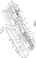
- the article of furniture includes a housing (not shown), a drawer (not shown) that is operable to be opened (i.e., being drawn out from the housing) or closed (i.e., being pushed into the housing) relative to the housing, and a slide rail mechanism 1.
- the slide rail mechanism 1 includes a fixed rail unit 11 that is fixedly connected to the housing, and a movable rail unit 12 that is co-movably connected to the drawer.
- the movable rail unit 12 is reciprocally movable along the fixed rail unit 11 in an energy-storing direction 91 and an energy-release direction 92 that is different from the energy-storing direction 91.
- the energy-storing direction 91 is the direction in which the drawer is pushed into the housing, and is oriented toward a rear side of the housing.
- the energy-release direction 92 is parallel to and opposite to the energy-storing direction 91, is the direction in which the drawer is drawn out from the housing, and is oriented toward a front side of the housing.
- This embodiment is exemplified to be used in a drawer, but may be used in any article that is movable along a rail.
- the first embodiment of the rebound device includes a push mechanism 2, a motion guide mechanism 3, a force-creating mechanism 4 and an accessing mechanism 7.
- the push mechanism 2 includes a push member 23, an urge unit 28 that is co-movably mounted to the movable rail unit 12, and an auxiliary push member 29 that is pivotally connected to the push member 23.
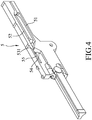
- the push member 23 has a guide groove 237 that is formed in a bottom surface of the push member 23 and that has an entrance 238 at an end thereof, a push surface 235 that is located at another end of the guide groove 237 distal from the entrance 238, and an urge surface 236 that faces toward the energy-release direction 92.
- the urge unit 28 is connected to the drawer via the movable rail unit 12, and is for pushing the urge surface 236 of the push member 23 to move the push member 23 in the energy-storing direction 91.
- the auxiliary push member 29 has an auxiliary connecting portion 291 that is pivotally connected to the push member 23, and an auxiliary guide pin 293 that extends downwardly.
- the auxiliary push member 29 is movable along with the push member 23, and is pivotable relative to the push member 23.
- the motion guide mechanism 3 includes a movable slide cover 31, a base seat 32 that is fixedly connected to the fixed rail unit 11, a latch member 33 that is pivotally connected to the base seat 32, and a driven member 34 that is pivotally connected to the slide cover 31.
- the slide cover 31 is slidably disposed on the base seat 32, and has a driven connecting portion 316, and a latch groove unit 5 that is formed in a bottom surface thereof.
- the push member 23 is slidably mounted to the slide cover 31.
- the latch groove unit 5 includes an energy-storing groove 51, an energy-release groove 52, a positioning portion 531 that is disposed between the energy-storing groove 51 and the energy-release groove 52, a transition block 54 (see Figure 7 ) that corresponds to the positioning portion 531 and that has an inclined surface, and a transition groove 55 that is located at one side of the transition block 54 and that is in spatial communication with the positioning portion 531.
- the base seat 32 has a bottom wall 321, a driven groove unit 6 that is formed in a top surface of the bottom wall 321, and an auxiliary groove 35 that is formed in the top surface of the bottom wall 321.
- the driven groove unit 6 includes an energy-storing groove 61 that extends in the energy-storing direction 91, a bent groove 62 that is located at an end of the energy-storing groove 61, an energy-release groove 63, and a block member 64 that is surrounded by the energy-storing groove 61, the bent groove 62 and the energy-release groove 63.
- the energy-release groove 63 has a first portion that extends from the bent groove 62 in the energy-release direction 92, and a second portion that is bent from the first portion and that extends to the other end of the energy-storing groove 61 distal from the bent groove 62.
- the driven groove unit 6 defines an energy-storing initial point (X) at an end of the energy-storing groove 61, and an energy-storing end point (Y) at the bent groove 62.
- the auxiliary groove 35 permits the auxiliary guide pin 293 of the auxiliary push member 29 to move therealong, so as to guide pivotal movement of the auxiliary push member 29 relative to the push member 23.
- the latch member 33 is pivotally mounted to the base seat 32, and has a latch body 331 that is located above the base seat 32 and that is formed with a pushed surface 334 (see Figures 6 and 7 ), a latch pivoted portion 332 that protrudes from a bottom surface of the latch body 331 and that is pivotally connected to the base seat 32, and a latch pin portion 333 that protrudes upwardly from the latch body 331 and that is movable within the latch groove unit 5.
- the driven member 34 is pivotally mounted to the slide cover 31, and has a driven body 341 that is located below the slide cover 31, a driven pivoted portion 342 that protrudes from the driven body 341 and that is pivotally connected to the driven connecting portion 316 of the slide cover 31, a driven projection 343 that projects from the driven body 341 and that is located on the path of movement of the push member 23, a first driven pin portion 344 that protrudes downwardly from the driven body 341, and a pushing portion 345 that is adjacent to the first driven pin portion 344.
- the driven projection 343 has a second driven pin portion 346 that protrudes upwardly and that is movable within the guide groove 237 of the push member 23.
- the first driven pin portion 344 is movable along the energy-storing groove 61, the bent groove 62 and the energy-release groove 63 of the driven groove unit 6.
- the driven member 34 of this embodiment pivots relative to the slide cover 31 about the driven connecting portion 316.
- the force-creating mechanism 4 interconnects the base seat 32 and the slide cover 31, and is able to store elastic energy for providing at least one restoring force that is oriented in the energy-release direction 92.
- the force-creating mechanism 4 is operable to provide a first-stage restoring force and a second-stage restoring force that are sequentially applied on the slide cover 31 and that are oriented in the energy-release direction 92.
- the force-creating mechanism 4 includes a plurality of springs 41. Each of the springs 41 is configured as an extension spring, extends in the energy-storing direction 91, and has a first end 411 that is connected to the base seat 32, and a second end 412 that is connected to the slide cover 31.
- the accessing mechanism 7 includes a transmission member 71, an accessing member 72 and an accessing resilient member 73.
- the transmission member 71 is pivotably mounted to the base seat 32, and has a first pivoted portion 710 that is pivoted to the base seat 32, a pushed portion 711 and a pushing portion 712 that are respectively located at two opposite sides of the first pivoted portion 710.
- the accessing member 72 is elongated, extends in the energy-storing direction 91, and has a first end portion 721 that is proximate to the pushing portion 712 of the transmission member 71, a second end portion 722 that is opposite to the first end portion 721, and an urging portion 723 that is located between the first end portion 721 and the second end portion 722 and that protrudes toward the latch member 33.
- the urging portion 723 of the accessing member 72 is for pushing the pushed surface 334 of the latch member 33.
- the accessing resilient member 73 is disposed between a wall section of the base seat 32 and the second end portion 722 of the accessing member 72, and resiliently biases the accessing member 72 in the energy-storing direction 91.
- the drawer, the movable rail unit 12 (see Figure 1 ) and the push mechanism 2 are operable to switch between an energy-storing initial state (see Figures 5 , 6 and 7 ), and an energy-stored state (see Figure 11 ) .
- the drawer in the energy-storing initial state, the drawer is opened, the slide cover 31 is at an energy-storing initial position, the latch pin portion 333 of the latch member 33 is at an energy-storing initial point of the energy-storing groove 51 of the latch groove unit 5, the first driven pin portion 344 of the driven member 34 is at the energy-storing initial point (X) of the driven groove unit 6, and the second driven pin portion 346 of the driven member 34 is at the entrance 238 of the guide groove 237 of the push member 23.
- the drawer is pushed in the energy-storing direction 91 (as shown by the arrow (A) in Figure 5 ) so that the movable rail unit 12 (see Figure 2 ) and the urge unit 28 are moved in the energy-storing direction 91.
- the urge unit 28 pushes and moves the push member 23 in the energy-storing direction 91, so that the second driven pin portion 346 of the driven member 34 enters the entrance 238 of the guide groove 237 of the push member 23, and that the push member 23 pushes the driven projection 343 of the driven member 34 to move the driven member 34 in the energy-storing direction 91.
- the first driven pin portion 344 of the driven member 34 moves along the energy-storing groove 61 of the driven groove unit 6 and moves relative to the latch pin portion 333 of the latch member 33. Since the driven pivoted portion 342 of the driven member 34 is pivotally connected to the driven connecting portion 316 of the slide cover 31, the movement of the driven member 34 in the energy-storing direction 91 drives movement of the slide cover 31 in the energy-storing direction 91.
- the springs 41 of the force-creating mechanism 4 are stretched to store elastic energy.
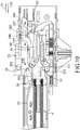
- the latch pin portion 333 of the latch member 33 Since the latch member 33 is pivotally connected to the base seat 32 and since the latch pin portion 333 of the latch member 33 moves in the energy-storing groove 51 of the latch groove unit 5, during the movement of the slide cover 31 relative to the base seat 32 in the energy-storing direction 91, the latch pin portion 333 of the latch member 33 gradually approaches the transition groove 55 from an end of the energy-storing groove 51 distal from the transition groove 55 (i.e., the energy-storing initial point) . In Figures 8 and 9 , the latch pin portion 333 is in contact with the transition block 54.
- the latch pin portion 333 of the latch member 33 then moves past the transition block 54 and enters the transition groove 55.
- the force-creating mechanism 4 is configured to generate the first-stage restoring force after the abovementioned operation.
- the movement of the push member 23 also drives movement of the auxiliary push member 29.
- the movement of the second driven pin portion 346 of the driven member 34 transverse to the energy-storing direction 91 is limited by the guide groove 237 of the push member 23, so the first driven pin portion 344 of the driven member 34 is temporarily positioned relative to the bent groove 62.
- the push member 23 is continuously driven by the urge unit 28 to move in the energy-storing direction 91.
- the abovementioned movement of the push member 23 in the energy-storing direction 91 does not drive movement of the driven member 34.
- the movement of the push member 23 in the energy-storing direction 91 may be buffered by a ratchet mechanism so that the drawer can be prevented from being closed fiercely.
- the first driven pin portion 344 of the driven member 34 is permitted to move within the bent groove 62 of the driven groove unit 6, the first-stage restoring force generated by the force-creating mechanism 4 immediately moves the slide cover 31 relative to the latch member 33 in the energy-release direction 92, so that the latch pin portion 333 of the latch member 33 engages the positioning portion 531 and that the first driven pin portion 344 of the driven member 34 moves along the bent groove 62 to rotate the driven member 34 relative to the slide cover 31.
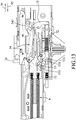
- the slide cover 31 is at an energy-stored position after the abovementioned operation ( Figure 11 ).
- the movable rail unit 12 is in the energy-stored state, and the first driven pin portion 344 of the driven member 34 is at the energy-storing end point (Y).
- the distance of the abovementioned movement of the slide cover 31, in which the slider cover 31 moves the latch pin portion 333 of the latch member 33 relative to the slide cover 31 from the transition groove 55 to the positioning portion 531, is about a few millimeters.
- the rebound device provides two manners in which the drawer is opened. The first one is to directly draw the drawer forwardly in the energy-release direction 92, and the second one is to depress the drawer rearwardly in the energy-storing direction 91 so that the drawer can be opened by the restoring force generated by the springs 41 of the force-creating mechanism 4.
- the pushing portion 345 of the driven member 34 moves in the energy-storing direction 91 to push the pushed portion 711 of the transmission member 71 so as to rotate the transmission member 71 clockwise, and then the pushing portion 712 of the transmission member 71 pushes the first end portion 721 of the accessing member 72 to move the accessing member 72 in the energy-release direction 92 against the biasing action of the accessing resilient member 73, so that the urging portion 723 of the accessing member 72 pushes the pushed surface 334 of the latch member 33 to rotate the latch member 33 clockwise.
- the latch pin portion 333 of the latch member 33 moves toward the transition block 54 rather than toward the transition groove 55 that is aligned with the positioning portion 531 (i.e., the latch pin portion 333 is moved away from the transition groove 55).
- the springs 41 of the force-creating mechanism 4 is further stretched to generate the second-stage restoring force after the abovementioned operation.
- the rebound device is configured such that further movement of the driven member 34 in the energy-storing direction 91 (also further movement of the movable rail unit 12 in the energy-storing direction 91) drives the latch pin portion 333 to further move away from the transition groove 55 by virtue of the accessing mechanism 7.
- a distance between the latch pin portion 333 and the positioning portion 531 is 1.5 millimeters.
- the distance between the latch pin portion 333 and the positioning portion 531 is 5 millimeters.
- the driven projection 343 of the driven member 34 pushes the push surface 235 of the push member 23 so that the push member 23 pushes and moves the urge unit 28 in the energy-release direction 92, and the first driven pin portion 344 of the driven member 34 moves back to the energy-storing initial point (X) at the energy-storing groove 61 of the driven groove unit 6 via the energy-release groove 63.
- the auxiliary push member 29 moves back onto the path of movement of the urge unit 28.
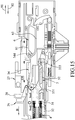
- the urge unit 28 has the tendency to move in the energy-release direction 92 (as shown by the arrow (B) in Figure 15 ), so as to hit and move the auxiliary push member 29 in the energy-release direction 92.
- the auxiliary push member 29 drives the push member 23 to move in the energy-release direction 92, and the second driven pin portion 346 of the driven member 34 is guided by the guide groove 237 (see Figure 4 ) of the push member 23 to rotate the driven member 34 such that the first driven pin portion 344 of the driven member 34 moves from the energy-release groove 63 into the energy-storing groove 61.
- the slide cover 31 is moved by the force-creating mechanism 4 again back to the energy-storing initial position, the latch pin portion 333 of the latch member 33 moves back to the energy-storing initial point of the energy-storing groove 51 of the latch groove unit 5, the first driven pin portion 344 of the driven member 34 moves back to the energy-storing initial point (X) of the driven groove unit 6, and the auxiliary push member 29 is retracted into the slide cover 31, as shown in Figure 5 .
- the urge unit 28 can therefore freely move past the auxiliary push member 29 for fully opening the drawer.
- the accessing member 72 is biased by the accessing resilient member 73 to move to its original position (see Figures 5 and 6 ).
- the following closing operation of the drawer is the same as the above.
- the movement of the slide cover 31 in the energy-release direction 92 may be buffered by a ratchet mechanism.
- the latch pin portion 333 engages the positioning portion 531.
- the latch pin portion 333 is disengaged from the positioning portion 531, and the accessing member 72 moves away from an original position in response to the movement of the movable rail unit 12 such that the urging portion 723 of the accessing member 72 pushes the latch member 33 to move the latch pin portion 333 away from the transition groove 55.
- the latch pin portion 333 of the latch member 33 is configured to move into the transition groove 55. After the external force is removed, the latch pin portion 333 moves to re-engage the positioning portion 531.
- the concept in this disclosure is to store energy by relative movement between two objects, and to drive relative movement between two objects by releasing the stored energy.
- either of the two objects need not be limited to be fixed, and the two objects are not limited to move toward each other or move away from each other.
- the positioning portion 531 of the latch groove unit 5 is configured to be aligned with the transition groove 55 in the energy-release direction 92.
- the positioning portion 531 may have other configuration.
Landscapes
- Engineering & Computer Science (AREA)
- Mechanical Engineering (AREA)
- General Engineering & Computer Science (AREA)
- Drawers Of Furniture (AREA)
- Seats For Vehicles (AREA)
- Vehicle Step Arrangements And Article Storage (AREA)
Applications Claiming Priority (1)
| Application Number | Priority Date | Filing Date | Title |
|---|---|---|---|
| TW108114444A TWI788558B (zh) | 2019-04-25 | 2019-04-25 | 反彈滑軌解鎖結構 |
Publications (1)
| Publication Number | Publication Date |
|---|---|
| EP3730002A1 true EP3730002A1 (fr) | 2020-10-28 |
Family
ID=70285559
Family Applications (1)
| Application Number | Title | Priority Date | Filing Date |
|---|---|---|---|
| EP20169152.4A Withdrawn EP3730002A1 (fr) | 2019-04-25 | 2020-04-09 | Dispositif à rebond pour rails coulissants |
Country Status (6)
| Country | Link |
|---|---|
| US (1) | US11406186B2 (fr) |
| EP (1) | EP3730002A1 (fr) |
| JP (1) | JP2020179165A (fr) |
| KR (1) | KR20200125903A (fr) |
| CN (1) | CN111839042B (fr) |
| TW (1) | TWI788558B (fr) |
Families Citing this family (9)
| Publication number | Priority date | Publication date | Assignee | Title |
|---|---|---|---|---|
| DE102021106384B4 (de) * | 2021-03-16 | 2023-11-02 | Titus D.O.O. Dekani | Bewegungsanordnung |
| TWI796973B (zh) * | 2022-03-18 | 2023-03-21 | 川湖科技股份有限公司 | 鎖裝置 |
| DE102023110428A1 (de) * | 2023-04-24 | 2024-10-24 | Grass Gmbh | Vorrichtung für die Bewegungssteuerung einer Schienenführung, Schienenführung und Möbel |
| TWM652071U (zh) * | 2023-06-29 | 2024-03-01 | 百富股份有限公司 | 抽屜自彈緩關裝置 |
| US12514366B2 (en) | 2023-09-01 | 2026-01-06 | Haier Us Appliance Solutions, Inc. | Mount assembly for a soft close mechanism of a slide assembly |
| US12564305B2 (en) | 2023-10-17 | 2026-03-03 | Haier Us Appliance Solutions, Inc. | Trigger assembly for a slide assembly of a dishwashing appliance |
| US12599228B2 (en) | 2023-10-17 | 2026-04-14 | Haier Us Appliance Solutions, Inc. | Locating slot for a trigger support arm of a slide assembly |
| US12599283B2 (en) | 2023-11-03 | 2026-04-14 | Haier Us Appliance Solutions, Inc. | Universal trigger assembly for a slide assembly |
| KR102923827B1 (ko) * | 2023-11-07 | 2026-02-09 | (주)세고스 | 푸쉬 오픈 장치 |
Citations (4)
| Publication number | Priority date | Publication date | Assignee | Title |
|---|---|---|---|---|
| US5040833A (en) | 1989-05-10 | 1991-08-20 | Julius Blum Gesellschaft M.B.H. | Closing device for drawers |
| TW201242540A (en) | 2011-04-27 | 2012-11-01 | King Slide Works Co Ltd | Closing device with an engaging configuration |
| WO2013073489A1 (fr) * | 2011-11-16 | 2013-05-23 | 中西金属工業株式会社 | Unité de mécanisme combinant un mécanisme de fermeture douce et un mécanisme d'ouverture par poussée |
| EP3295828A1 (fr) * | 2016-09-19 | 2018-03-21 | Slide Mei Yao International Co., Ltd. | Dispositif à ouverture par pression |
Family Cites Families (12)
| Publication number | Priority date | Publication date | Assignee | Title |
|---|---|---|---|---|
| JP2004154322A (ja) * | 2002-11-06 | 2004-06-03 | Thk Co Ltd | スライドレールの自動引出し機構及び引出し装置 |
| CN100482961C (zh) * | 2006-06-02 | 2009-04-29 | 鸿富锦精密工业(深圳)有限公司 | 滑轨定位装置 |
| US8393693B2 (en) * | 2008-12-30 | 2013-03-12 | Sun Chain Metal Industry Co., Ltd. | Return device for a drawer |
| US8485616B2 (en) * | 2011-02-09 | 2013-07-16 | King Slide Works Co., Ltd. | Slide assembly with buffering member for reducing impact and noise |
| US9750347B2 (en) * | 2012-04-30 | 2017-09-05 | Hardware Resources, Inc. | Pressure release slide latch mechanism |
| US9648952B2 (en) * | 2012-04-30 | 2017-05-16 | Hardware Resources, Inc. | Pressure release slide latch mechanism |
| US8939525B1 (en) * | 2014-01-27 | 2015-01-27 | Martas Precision Slide Co., Ltd. | Self-closing buffer and automatic rebound mechanism for slide rail |
| TWI601499B (zh) * | 2015-09-25 | 2017-10-11 | Side lock slide automatic opening device | |
| TWI528920B (zh) * | 2015-11-12 | 2016-04-11 | 川湖科技股份有限公司 | 用於滑軌總成的驅動機構及導引配件 |
| CN105996493B (zh) * | 2016-07-28 | 2018-06-19 | 青岛三维海容机电有限公司 | 一种抽屉及包含该抽屉的柜体 |
| TW201811231A (zh) * | 2016-09-19 | 2018-04-01 | 陳崇堯 | 自開彈壓裝置 |
| CN106760987B (zh) * | 2017-01-09 | 2018-08-28 | 东莞市怡丰锁业有限公司 | 一种密码扣锁 |
-
2019
- 2019-04-25 TW TW108114444A patent/TWI788558B/zh active
-
2020
- 2020-02-18 CN CN202010099428.1A patent/CN111839042B/zh active Active
- 2020-04-08 US US16/843,170 patent/US11406186B2/en active Active
- 2020-04-09 EP EP20169152.4A patent/EP3730002A1/fr not_active Withdrawn
- 2020-04-20 JP JP2020074487A patent/JP2020179165A/ja active Pending
- 2020-04-23 KR KR1020200049443A patent/KR20200125903A/ko not_active Withdrawn
Patent Citations (4)
| Publication number | Priority date | Publication date | Assignee | Title |
|---|---|---|---|---|
| US5040833A (en) | 1989-05-10 | 1991-08-20 | Julius Blum Gesellschaft M.B.H. | Closing device for drawers |
| TW201242540A (en) | 2011-04-27 | 2012-11-01 | King Slide Works Co Ltd | Closing device with an engaging configuration |
| WO2013073489A1 (fr) * | 2011-11-16 | 2013-05-23 | 中西金属工業株式会社 | Unité de mécanisme combinant un mécanisme de fermeture douce et un mécanisme d'ouverture par poussée |
| EP3295828A1 (fr) * | 2016-09-19 | 2018-03-21 | Slide Mei Yao International Co., Ltd. | Dispositif à ouverture par pression |
Also Published As
| Publication number | Publication date |
|---|---|
| CN111839042A (zh) | 2020-10-30 |
| JP2020179165A (ja) | 2020-11-05 |
| US20200337456A1 (en) | 2020-10-29 |
| TW202038813A (zh) | 2020-11-01 |
| US11406186B2 (en) | 2022-08-09 |
| CN111839042B (zh) | 2024-07-02 |
| TWI788558B (zh) | 2023-01-01 |
| KR20200125903A (ko) | 2020-11-05 |
Similar Documents
| Publication | Publication Date | Title |
|---|---|---|
| US11406186B2 (en) | Rebound device for slide rails | |
| US11122893B2 (en) | Self-opening device | |
| US5344226A (en) | Safety device for drawers | |
| US20200084905A1 (en) | Pull-out aiding device and chassis-wall module with pull-out aiding function | |
| US20040227438A1 (en) | Automatic return guiding device for a track device | |
| US4170042A (en) | Readily releasable powered visor-and-lock assembly for helmet | |
| KR20110083625A (ko) | 특히 이동 가구 부재용 자동 개폐장치 | |
| CA2103478A1 (fr) | Verrouillage pour tiroir de classeur | |
| US4156499A (en) | Magazine latching assembly for a compact tacker | |
| TW201711600A (zh) | 側鎖式滑軌的自動開啟裝置 | |
| EP3295828A1 (fr) | Dispositif à ouverture par pression | |
| US20240065438A1 (en) | Slide rail assembly and slide rail kit | |
| CN109984496A (zh) | 自开弹出装置 | |
| CN211212135U (zh) | 滑轨组件、抽屉组件及家具 | |
| US20240164522A1 (en) | Drawer divider | |
| EP2371241B1 (fr) | Ensemble de rails de tiroir avec dispositif d'ouverture | |
| JP3154197U (ja) | 家具用可動部材の自動移動装置 | |
| CN107912898B (zh) | 一种家具抽屉的按压反弹防脱机构 | |
| EP3756508A1 (fr) | Dispositif à ouverture automatique | |
| JP2004065701A (ja) | 引出し装置 | |
| CN219289040U (zh) | 一种钢珠轨的阻尼反弹装置 | |
| CN201119590Y (zh) | 滑轨的制动装置 | |
| CN216256230U (zh) | 一种钢珠轨阻尼反弹装置 | |
| US12383060B2 (en) | Device for self-bouncing and slowly closing drawer | |
| US20240360870A1 (en) | Slide rail assembly |
Legal Events
| Date | Code | Title | Description |
|---|---|---|---|
| PUAI | Public reference made under article 153(3) epc to a published international application that has entered the european phase |
Free format text: ORIGINAL CODE: 0009012 |
|
| STAA | Information on the status of an ep patent application or granted ep patent |
Free format text: STATUS: THE APPLICATION HAS BEEN PUBLISHED |
|
| AK | Designated contracting states |
Kind code of ref document: A1 Designated state(s): AL AT BE BG CH CY CZ DE DK EE ES FI FR GB GR HR HU IE IS IT LI LT LU LV MC MK MT NL NO PL PT RO RS SE SI SK SM TR |
|
| AX | Request for extension of the european patent |
Extension state: BA ME |
|
| STAA | Information on the status of an ep patent application or granted ep patent |
Free format text: STATUS: REQUEST FOR EXAMINATION WAS MADE |
|
| 17P | Request for examination filed |
Effective date: 20210426 |
|
| RBV | Designated contracting states (corrected) |
Designated state(s): AL AT BE BG CH CY CZ DE DK EE ES FI FR GB GR HR HU IE IS IT LI LT LU LV MC MK MT NL NO PL PT RO RS SE SI SK SM TR |
|
| STAA | Information on the status of an ep patent application or granted ep patent |
Free format text: STATUS: EXAMINATION IS IN PROGRESS |
|
| 17Q | First examination report despatched |
Effective date: 20211111 |
|
| STAA | Information on the status of an ep patent application or granted ep patent |
Free format text: STATUS: THE APPLICATION IS DEEMED TO BE WITHDRAWN |
|
| 18D | Application deemed to be withdrawn |
Effective date: 20220524 |