EP3730101A1 - Capuchon de protection ventilé pour un distributeur de liquide - Google Patents
Capuchon de protection ventilé pour un distributeur de liquide Download PDFInfo
- Publication number
- EP3730101A1 EP3730101A1 EP19171379.1A EP19171379A EP3730101A1 EP 3730101 A1 EP3730101 A1 EP 3730101A1 EP 19171379 A EP19171379 A EP 19171379A EP 3730101 A1 EP3730101 A1 EP 3730101A1
- Authority
- EP
- European Patent Office
- Prior art keywords
- layer
- surface structure
- protective cap
- ventilation
- liquid
- Prior art date
- Legal status (The legal status is an assumption and is not a legal conclusion. Google has not performed a legal analysis and makes no representation as to the accuracy of the status listed.)
- Granted
Links
Images





Classifications
-
- A—HUMAN NECESSITIES
- A61—MEDICAL OR VETERINARY SCIENCE; HYGIENE
- A61J—CONTAINERS SPECIALLY ADAPTED FOR MEDICAL OR PHARMACEUTICAL PURPOSES; DEVICES OR METHODS SPECIALLY ADAPTED FOR BRINGING PHARMACEUTICAL PRODUCTS INTO PARTICULAR PHYSICAL OR ADMINISTERING FORMS; DEVICES FOR ADMINISTERING FOOD OR MEDICINES ORALLY; BABY COMFORTERS; DEVICES FOR RECEIVING SPITTLE
- A61J1/00—Containers specially adapted for medical or pharmaceutical purposes
- A61J1/05—Containers specially adapted for medical or pharmaceutical purposes for collecting, storing or administering blood, plasma or medical fluids ; Infusion or perfusion containers
- A61J1/06—Ampoules or carpules
- A61J1/067—Flexible ampoules, the contents of which are expelled by squeezing
-
- B—PERFORMING OPERATIONS; TRANSPORTING
- B65—CONVEYING; PACKING; STORING; HANDLING THIN OR FILAMENTARY MATERIAL
- B65D—CONTAINERS FOR STORAGE OR TRANSPORT OF ARTICLES OR MATERIALS, e.g. BAGS, BARRELS, BOTTLES, BOXES, CANS, CARTONS, CRATES, DRUMS, JARS, TANKS, HOPPERS, FORWARDING CONTAINERS; ACCESSORIES, CLOSURES, OR FITTINGS THEREFOR; PACKAGING ELEMENTS; PACKAGES
- B65D47/00—Closures with filling and discharging, or with discharging, devices
- B65D47/04—Closures with discharging devices other than pumps
- B65D47/06—Closures with discharging devices other than pumps with pouring spouts or tubes; with discharge nozzles or passages
- B65D47/18—Closures with discharging devices other than pumps with pouring spouts or tubes; with discharge nozzles or passages for discharging drops; Droppers
-
- B—PERFORMING OPERATIONS; TRANSPORTING
- B65—CONVEYING; PACKING; STORING; HANDLING THIN OR FILAMENTARY MATERIAL
- B65D—CONTAINERS FOR STORAGE OR TRANSPORT OF ARTICLES OR MATERIALS, e.g. BAGS, BARRELS, BOTTLES, BOXES, CANS, CARTONS, CRATES, DRUMS, JARS, TANKS, HOPPERS, FORWARDING CONTAINERS; ACCESSORIES, CLOSURES, OR FITTINGS THEREFOR; PACKAGING ELEMENTS; PACKAGES
- B65D47/00—Closures with filling and discharging, or with discharging, devices
- B65D47/04—Closures with discharging devices other than pumps
- B65D47/32—Closures with discharging devices other than pumps with means for venting
-
- A—HUMAN NECESSITIES
- A61—MEDICAL OR VETERINARY SCIENCE; HYGIENE
- A61F—FILTERS IMPLANTABLE INTO BLOOD VESSELS; PROSTHESES; DEVICES PROVIDING PATENCY TO, OR PREVENTING COLLAPSING OF, TUBULAR STRUCTURES OF THE BODY, e.g. STENTS; ORTHOPAEDIC, NURSING OR CONTRACEPTIVE DEVICES; FOMENTATION; TREATMENT OR PROTECTION OF EYES OR EARS; BANDAGES, DRESSINGS OR ABSORBENT PADS; FIRST-AID KITS
- A61F9/00—Methods or devices for treatment of the eyes; Devices for putting in contact-lenses; Devices to correct squinting; Apparatus to guide the blind; Protective devices for the eyes, carried on the body or in the hand
- A61F9/0008—Introducing ophthalmic products into the ocular cavity or retaining products therein
-
- A—HUMAN NECESSITIES
- A61—MEDICAL OR VETERINARY SCIENCE; HYGIENE
- A61J—CONTAINERS SPECIALLY ADAPTED FOR MEDICAL OR PHARMACEUTICAL PURPOSES; DEVICES OR METHODS SPECIALLY ADAPTED FOR BRINGING PHARMACEUTICAL PRODUCTS INTO PARTICULAR PHYSICAL OR ADMINISTERING FORMS; DEVICES FOR ADMINISTERING FOOD OR MEDICINES ORALLY; BABY COMFORTERS; DEVICES FOR RECEIVING SPITTLE
- A61J1/00—Containers specially adapted for medical or pharmaceutical purposes
- A61J1/14—Details; Accessories therefor
- A61J1/1412—Containers with closing means, e.g. caps
-
- A—HUMAN NECESSITIES
- A61—MEDICAL OR VETERINARY SCIENCE; HYGIENE
- A61J—CONTAINERS SPECIALLY ADAPTED FOR MEDICAL OR PHARMACEUTICAL PURPOSES; DEVICES OR METHODS SPECIALLY ADAPTED FOR BRINGING PHARMACEUTICAL PRODUCTS INTO PARTICULAR PHYSICAL OR ADMINISTERING FORMS; DEVICES FOR ADMINISTERING FOOD OR MEDICINES ORALLY; BABY COMFORTERS; DEVICES FOR RECEIVING SPITTLE
- A61J1/00—Containers specially adapted for medical or pharmaceutical purposes
- A61J1/14—Details; Accessories therefor
- A61J1/1443—Containers with means for dispensing liquid medicaments in a filtered or sterile way, e.g. with bacterial filters
- A61J1/145—Containers with means for dispensing liquid medicaments in a filtered or sterile way, e.g. with bacterial filters using air filters
-
- A—HUMAN NECESSITIES
- A61—MEDICAL OR VETERINARY SCIENCE; HYGIENE
- A61M—DEVICES FOR INTRODUCING MEDIA INTO, OR ONTO, THE BODY; DEVICES FOR TRANSDUCING BODY MEDIA OR FOR TAKING MEDIA FROM THE BODY; DEVICES FOR PRODUCING OR ENDING SLEEP OR STUPOR
- A61M11/00—Sprayers or atomisers specially adapted for therapeutic purposes
- A61M11/006—Sprayers or atomisers specially adapted for therapeutic purposes operated by applying mechanical pressure to the liquid to be sprayed or atomised
-
- B—PERFORMING OPERATIONS; TRANSPORTING
- B01—PHYSICAL OR CHEMICAL PROCESSES OR APPARATUS IN GENERAL
- B01D—SEPARATION
- B01D46/00—Filters or filtering processes specially modified for separating dispersed particles from gases or vapours
- B01D46/0027—Filters or filtering processes specially modified for separating dispersed particles from gases or vapours with additional separating or treating functions
- B01D46/0028—Filters or filtering processes specially modified for separating dispersed particles from gases or vapours with additional separating or treating functions provided with antibacterial or antifungal means
-
- B—PERFORMING OPERATIONS; TRANSPORTING
- B01—PHYSICAL OR CHEMICAL PROCESSES OR APPARATUS IN GENERAL
- B01D—SEPARATION
- B01D46/00—Filters or filtering processes specially modified for separating dispersed particles from gases or vapours
- B01D46/54—Particle separators, e.g. dust precipitators, using ultra-fine filter sheets or diaphragms
- B01D46/543—Particle separators, e.g. dust precipitators, using ultra-fine filter sheets or diaphragms using membranes
-
- B—PERFORMING OPERATIONS; TRANSPORTING
- B29—WORKING OF PLASTICS; WORKING OF SUBSTANCES IN A PLASTIC STATE IN GENERAL
- B29C—SHAPING OR JOINING OF PLASTICS; SHAPING OF MATERIAL IN A PLASTIC STATE, NOT OTHERWISE PROVIDED FOR; AFTER-TREATMENT OF THE SHAPED PRODUCTS, e.g. REPAIRING
- B29C45/00—Injection moulding, i.e. forcing the required volume of moulding material through a nozzle into a closed mould; Apparatus therefor
- B29C45/14—Injection moulding, i.e. forcing the required volume of moulding material through a nozzle into a closed mould; Apparatus therefor incorporating preformed parts or layers, e.g. injection moulding around inserts or for coating articles
-
- B—PERFORMING OPERATIONS; TRANSPORTING
- B29—WORKING OF PLASTICS; WORKING OF SUBSTANCES IN A PLASTIC STATE IN GENERAL
- B29C—SHAPING OR JOINING OF PLASTICS; SHAPING OF MATERIAL IN A PLASTIC STATE, NOT OTHERWISE PROVIDED FOR; AFTER-TREATMENT OF THE SHAPED PRODUCTS, e.g. REPAIRING
- B29C45/00—Injection moulding, i.e. forcing the required volume of moulding material through a nozzle into a closed mould; Apparatus therefor
- B29C45/14—Injection moulding, i.e. forcing the required volume of moulding material through a nozzle into a closed mould; Apparatus therefor incorporating preformed parts or layers, e.g. injection moulding around inserts or for coating articles
- B29C45/1418—Injection moulding, i.e. forcing the required volume of moulding material through a nozzle into a closed mould; Apparatus therefor incorporating preformed parts or layers, e.g. injection moulding around inserts or for coating articles the inserts being deformed or preformed, e.g. by the injection pressure
-
- B—PERFORMING OPERATIONS; TRANSPORTING
- B65—CONVEYING; PACKING; STORING; HANDLING THIN OR FILAMENTARY MATERIAL
- B65D—CONTAINERS FOR STORAGE OR TRANSPORT OF ARTICLES OR MATERIALS, e.g. BAGS, BARRELS, BOTTLES, BOXES, CANS, CARTONS, CRATES, DRUMS, JARS, TANKS, HOPPERS, FORWARDING CONTAINERS; ACCESSORIES, CLOSURES, OR FITTINGS THEREFOR; PACKAGING ELEMENTS; PACKAGES
- B65D51/00—Closures not otherwise provided for
- B65D51/16—Closures not otherwise provided for with means for venting air or gas
- B65D51/1605—Closures not otherwise provided for with means for venting air or gas whereby the interior of the container is maintained in permanent gaseous communication with the exterior
- B65D51/1611—Closures not otherwise provided for with means for venting air or gas whereby the interior of the container is maintained in permanent gaseous communication with the exterior by means of an orifice, capillary or labyrinth passage
-
- B—PERFORMING OPERATIONS; TRANSPORTING
- B65—CONVEYING; PACKING; STORING; HANDLING THIN OR FILAMENTARY MATERIAL
- B65D—CONTAINERS FOR STORAGE OR TRANSPORT OF ARTICLES OR MATERIALS, e.g. BAGS, BARRELS, BOTTLES, BOXES, CANS, CARTONS, CRATES, DRUMS, JARS, TANKS, HOPPERS, FORWARDING CONTAINERS; ACCESSORIES, CLOSURES, OR FITTINGS THEREFOR; PACKAGING ELEMENTS; PACKAGES
- B65D51/00—Closures not otherwise provided for
- B65D51/16—Closures not otherwise provided for with means for venting air or gas
- B65D51/1605—Closures not otherwise provided for with means for venting air or gas whereby the interior of the container is maintained in permanent gaseous communication with the exterior
- B65D51/1616—Closures not otherwise provided for with means for venting air or gas whereby the interior of the container is maintained in permanent gaseous communication with the exterior by means of a filter
-
- B—PERFORMING OPERATIONS; TRANSPORTING
- B65—CONVEYING; PACKING; STORING; HANDLING THIN OR FILAMENTARY MATERIAL
- B65D—CONTAINERS FOR STORAGE OR TRANSPORT OF ARTICLES OR MATERIALS, e.g. BAGS, BARRELS, BOTTLES, BOXES, CANS, CARTONS, CRATES, DRUMS, JARS, TANKS, HOPPERS, FORWARDING CONTAINERS; ACCESSORIES, CLOSURES, OR FITTINGS THEREFOR; PACKAGING ELEMENTS; PACKAGES
- B65D83/00—Containers or packages with special means for dispensing contents
- B65D83/14—Containers for dispensing liquid or semi-liquid contents by internal gaseous pressure, i.e. aerosol containers comprising propellant
- B65D83/40—Closure caps
-
- A—HUMAN NECESSITIES
- A61—MEDICAL OR VETERINARY SCIENCE; HYGIENE
- A61M—DEVICES FOR INTRODUCING MEDIA INTO, OR ONTO, THE BODY; DEVICES FOR TRANSDUCING BODY MEDIA OR FOR TAKING MEDIA FROM THE BODY; DEVICES FOR PRODUCING OR ENDING SLEEP OR STUPOR
- A61M2205/00—General characteristics of the apparatus
- A61M2205/02—General characteristics of the apparatus characterised by a particular materials
- A61M2205/0205—Materials having antiseptic or antimicrobial properties, e.g. silver compounds, rubber with sterilising agent
-
- A—HUMAN NECESSITIES
- A61—MEDICAL OR VETERINARY SCIENCE; HYGIENE
- A61M—DEVICES FOR INTRODUCING MEDIA INTO, OR ONTO, THE BODY; DEVICES FOR TRANSDUCING BODY MEDIA OR FOR TAKING MEDIA FROM THE BODY; DEVICES FOR PRODUCING OR ENDING SLEEP OR STUPOR
- A61M2207/00—Methods of manufacture, assembly or production
- A61M2207/10—Device therefor
-
- B—PERFORMING OPERATIONS; TRANSPORTING
- B29—WORKING OF PLASTICS; WORKING OF SUBSTANCES IN A PLASTIC STATE IN GENERAL
- B29C—SHAPING OR JOINING OF PLASTICS; SHAPING OF MATERIAL IN A PLASTIC STATE, NOT OTHERWISE PROVIDED FOR; AFTER-TREATMENT OF THE SHAPED PRODUCTS, e.g. REPAIRING
- B29C45/00—Injection moulding, i.e. forcing the required volume of moulding material through a nozzle into a closed mould; Apparatus therefor
- B29C45/14—Injection moulding, i.e. forcing the required volume of moulding material through a nozzle into a closed mould; Apparatus therefor incorporating preformed parts or layers, e.g. injection moulding around inserts or for coating articles
- B29C45/1418—Injection moulding, i.e. forcing the required volume of moulding material through a nozzle into a closed mould; Apparatus therefor incorporating preformed parts or layers, e.g. injection moulding around inserts or for coating articles the inserts being deformed or preformed, e.g. by the injection pressure
- B29C2045/14237—Injection moulding, i.e. forcing the required volume of moulding material through a nozzle into a closed mould; Apparatus therefor incorporating preformed parts or layers, e.g. injection moulding around inserts or for coating articles the inserts being deformed or preformed, e.g. by the injection pressure the inserts being deformed or preformed outside the mould or mould cavity
-
- B—PERFORMING OPERATIONS; TRANSPORTING
- B65—CONVEYING; PACKING; STORING; HANDLING THIN OR FILAMENTARY MATERIAL
- B65D—CONTAINERS FOR STORAGE OR TRANSPORT OF ARTICLES OR MATERIALS, e.g. BAGS, BARRELS, BOTTLES, BOXES, CANS, CARTONS, CRATES, DRUMS, JARS, TANKS, HOPPERS, FORWARDING CONTAINERS; ACCESSORIES, CLOSURES, OR FITTINGS THEREFOR; PACKAGING ELEMENTS; PACKAGES
- B65D2205/00—Venting means
Definitions
- the invention relates to a ventilated protective cap, a ventilation insert, in particular for such a protective cap, and a liquid dispenser with such a protective cap.
- the invention also relates to corresponding production methods.
- Ventilated protective caps are used in liquid dispensers for pharmaceutical liquids in order to allow air to be exchanged between a cap interior and an environment after initial use. This serves the purpose of faster drying of liquid residues that have remained beyond the discharge opening of a dispenser. This prevents bacterial growth.
- the ventilation openings of ventilated protective caps also lead to the risk of germs entering from the environment, so that it has already been proposed to provide the ventilation opening with a sterile filter.
- the object of the invention is to provide a ventilated protective cap or a ventilation insert, in particular for such a protective cap, which allows adaptation to specific requirements at low cost.
- a ventilated protective cap for a liquid dispenser which has a cap wall which surrounds a cap interior.
- the cap wall has a ventilation opening that is spanned by a flexible surface structure. An edge area of the surface structure is fixed all around on an edge of the ventilation opening.
- planar structure of a protective cap according to the invention consists of at least two layers which are in direct contact with one another, but are not firmly connected to one another at least in a central area of the planar structure.
- the surface structure spans the at least one ventilation opening and thus ensures that an exchange of air between a cap interior and the surroundings is only possible through the surface structure when the protective cap is in place.
- the surface structure has a plurality of layers which preferably fulfill different functions. These layers are handled separately during production and are not directly connected to one another at least in a central area of preferably at least 9 mm 2 . In an edge area, however, they can be connected to one another in the course of production, in particular by joint injection molding with plastic or thermal joining to one another.
- the at least two layers which do not come together from a composite material, but are each produced individually from surfaces or webs of their specific type, provide a high degree of flexibility.
- the multiple layers can also be put together for small series of dispensers according to requirements.
- a layer which is designed as a sterile filter is usually included. This preferably has a separation limit of at most 1 ⁇ m, particularly preferably a separation limit of at most 0.5 ⁇ m. Even better sterility can be achieved with a cut-off limit of a maximum of 0.2 ⁇ m. Such a sterile filter prevents germs from entering through the ventilation opening.
- the filter layer can be designed as a depth filter or as a membrane filter.
- the depth filter has a three-dimensional structure, which bacteria can enter, but which separates the bacteria from the air flowing through.
- pores of a defined size are provided, by means of which germs are deposited before they enter the layer.
- One layer of the surface structure can be designed as an absorbent layer, which is provided for receiving a residual drop from a discharge opening of the dispenser, this layer preferably representing the first layer of the surface structure starting from the interior of the cap.
- this absorbent layer can lie directly on the end face of the main unit of the dispenser or be at a small distance from this end face.
- the layers can have a hydrophilic surface or a hydrophobic surface.
- a hydrophilic surface For example, it can be useful to make an absorbent layer hydrophilic in order to accelerate the absorption of liquid.
- a plurality of layers can also be designed to be hydrophilic to different degrees in order to absorb residual liquid through this and to conduct it to a particularly hydrophilic core layer.
- One layer of the surface structure can also be designed as a support layer, in particular an outermost layer.
- a support layer can give the surface structure mechanical stability. In this way, further layers of the surface structure can be protected against accidental and willful injuries.
- it can be a type of solid fabric.
- a design with several support layers, in particular a sterile filter layer on both sides, can also be expedient.
- a further layer which is expedient in some cases is a privacy protection layer that conceals at least one layer underneath. This is particularly useful for protective caps that are designed in color. Since sterile filters are usually colored for technical reasons and are often white, they are immediately noticeable on colored protective caps and may cause the misunderstanding that the corresponding layer should be removed as intended. A visual protection layer in the color of the plastic of the protective cap hides the sterile filter and therefore prevents the misunderstanding mentioned.
- a protective cap In a first variant of a protective cap according to the invention, it is provided that the at least two layers of the surface structure are held by a common molded support structure on the edge of the ventilation opening. It is provided here that the support structure protrudes over the edge region of the surface structure on one side or in particular preferably in one piece on both sides of the surface structure.
- two circumferential webs of the support structure protrude above and below the flexible surface structure over this and thereby fix the surface structure.
- the production is preferably carried out in that the multilayer surface structure is first introduced into an injection-molded cavity and then encapsulated with plastic, which forms the aforementioned two circumferential webs.
- a support structure with an annular fastening surface is provided on the edge of the ventilation opening.
- a first layer of the surface structure is thermally fastened to this fastening surface in an edge region.
- a second layer of the planar structure is thermally attached in an edge area, at least also to the edge area of the first layer.
- the layers of the planar structure are not overmolded, but rather thermally fastened to the aforementioned fastening surface or to one another.
- the connection is preferably produced by means of a hollow die which compresses the respective layers in the edge area and melts out, so that they enter into an intimate connection with one another or with the fastening surface.
- Other joining techniques such as laser welding and ultrasonic welding are also possible here.
- the protective cap can have a main component which at least for the most part forms a jacket wall of the cap wall and on which the support structure is provided in one piece. In such a case, with the exception of the layers of the surface structure above the ventilation opening, the cap can thus be produced in one piece.
- the protective cap has a main component which at least for the most part forms a jacket wall of the cap wall and has an opening for receiving a ventilation insert.
- the protective cap has, as a further component, a ventilation insert which is inserted sealingly into the opening and which comprises the surrounding support structure and the surface structure held and surrounded by it.
- the protective cap has a protective structure to protect the surface structure, the protective structure being designed as a component separate from the supporting structure and being connected to the supporting structure in a force-fitting or form-fitting manner.
- This protective structure which is preferably produced as a separate plastic part, can protect the surface structure to an even more secure extent than the above-mentioned support layer.
- the invention also relates to the ventilation insert already described, in particular for use in a cap according to the invention.
- the ventilation insert has a ventilation opening which is surrounded by a support structure and that the ventilation opening is spanned by a flexible surface structure, the edge area of which is fixed all around the support structure.
- the surface structure consists of the at least two layers already described, which lie directly against one another, but are not firmly connected to one another at least in a central area of the surface structure.
- the layers possible here include all the layers mentioned above with regard to the protective cap.
- the protective cap described can also be provided with a corresponding ventilation insert that the two layers of the surface structure are held by a common molded support structure at the edge of the ventilation opening, which protrudes over the edge area of the surface structure on one side or in one piece on both sides of the surface structure.
- a support structure with an annular fastening surface is provided at the edge of the ventilation opening, a first layer of the surface structure being thermally connected to the fastening surface in an edge region and a second layer of the surface structure being thermally connected to the edge region in an edge region the first layer is connected.
- connection of the ventilation insert can be fastened in a receptacle, in particular the protective cap described, by means of different connection techniques.
- a preferred design provides that the ventilation insert has a tapering and preferably at least partially conical jacket surface which allows easy insertion and, if necessary, the production of a self-locking press fit with the receptacle.
- the ventilation insert is fastened by means of a snap connection and accordingly has an external geometry that can be snapped behind.
- a threaded connection or an adhesive or welded connection are also possible. In the case of a welded connection, this can in particular be produced by means of laser welding or ultrasonic welding.
- the invention also relates to a liquid dispenser, in particular for pharmaceutical liquids.
- This liquid dispenser has a main unit, which in turn comprises a liquid reservoir, a conveying device and a discharge opening for dispensing the liquid.
- the delivery device can in particular be designed as a pumping device for delivering pressurelessly stored liquid or as a valve device for delivering pressurized fluid stored in a pressure accumulator.
- the conveying device is operated manually, liquid passes from the liquid reservoir to the discharge opening.
- the liquid reservoir can also be provided with a squeeze bottle, that is to say a bottle that can be compressed by manual application of force, which thus itself represents the conveying device.
- the liquid dispenser can be designed as a drop dispenser, that is to say for dispensing individual drops, in particular for application in the nose, in the ears or in the eyes.
- a drop dispenser preferably has a drop formation geometry surrounding the discharge opening, for example in the form of a concave or flat drop formation surface, which is preferably surrounded by a sharp-edged tear-off edge.
- a discharge valve is connected upstream of the discharge opening, which prevents the entry of germs here, but at the same time also prevents a residual drop from being sucked back.
- the liquid dispenser according to the invention has a ventilated protective cap of the type described above, which can be placed on the main unit and protects the discharge opening in the attached state.
- a ventilation insert of the type described above can be provided on this protective cap or in the case of an alternative use elsewhere on a liquid dispenser.
- a protective cap according to the invention and / or a ventilation unit according to the invention can also be expedient for other dispensers, for example also for spray dispensers for the atomized discharge of liquid.
- the protective cap is preferably provided with a surface structure with an absorbent or antibacterial layer, this layer being arranged directly above the discharge opening when the protective cap is in place, so that a residual drop remaining at the discharge opening can be picked up and / or decontaminated.
- the liquid dispenser When delivered, the liquid dispenser is filled with a pharmaceutical liquid.
- these are pharmaceutical liquids for the treatment of increased intraocular pressure (glaucoma treatment), for the treatment of dry eyes and for the treatment of allergies and inflammations.
- the groups of molecules alpha-2 agonists play here, e.g. B. brimonidine, prostaglandin analogs (tafluprost, latanoprost, bimatoprost, travoprost), beta-blockers, e.g. B. timolol, and carbonic anhydrase inhibitors, e.g. B. dorzolamide or hyaluronic acid compounds, film formers, e.g. B.
- methylcellulose compounds and cyclosporine or antihistamines z. B. olopatadine and levocabastine, steroids, e.g. B. Loteprdnol and dexamethasone, and NSAID, z. B. Keterolac, a role.
- the dispenser according to the invention can advantageously be used for liquids with molecules of one or more of the following types: trichloroacetic acid, trioxysalen, urea, zinc oxide, tacrolimus, clobetasol propionate, mometasone furoate, betamethasone dipropionate, fluocinonide, deoximetasone, ketonazone propionate, acetonazisonolone, triamcinazisonolone, clotrimone propionate, acetonazisonolone, ketonazone propionate, acetonazone propionate, acetonazone propionate, acetonazone propionate, acetonazisonolone , Miconazole, undecylenic acid, terbinafine, cyclopirox, tolnaftate, akziklovir, imiquimod, docosanol, finasteride, minoxidil, dexamet
- the invention also relates to a method for producing a protective cap of the type described above or a ventilation insert of the type described above.
- a protective cap whereby the method steps can also be used accordingly for producing a separate ventilation insert, which is then particularly shown in the inclusion of a protective cap is used.
- a first layer of a first flat material and a second layer of a second flat material are supplied continuously in the form of flat strips. If more layers are to be used, further flat strips must be provided accordingly.
- the at least two layers are pressed together by an upper-side punch and a lower-side punch and a cut is made surrounding the punch with a cutting contour, with which the two layers of the surface structure provided for the protective cap or the ventilation insert are separated from the flat Ribbons is separated.
- the two layers that are not firmly connected to one another are held between the two stamps.
- This multilayer surface structure is then inserted into an injection-molded cavity in a state fixed by the stamp.
- a plastic material for example an HDPE or PP, is then injected into the injection molding cavity, which forms a common support structure that is one-sided or in one piece on both sides of the surface structure protrudes over the edge area of the surface structure and fixes the layers of the surface structure.
- the two-sided stamps are spaced apart from the surface structure and in this case release the paths from an external environment to the surface structure and from the surface structure to an inner region of the protective cap.
- the special feature of the method described is, in particular, that the same means, namely the two mentioned punches, are used to press the at least two layers that are not connected to one another at this point in time and to position them in the cavity in such a way that they are attached to the desired location and are surrounded by plastic there.
- the stamps themselves keep the ventilation opening on both sides of the surface structure free of plastic.
- a base body of a ventilated protective cap or a ventilation insert which has a ventilation opening that is surrounded by a support structure with an annular fastening surface.
- a first layer of the surface structure and a second layer of the surface structure are placed one after the other or together in the ventilation opening in such a way that the edge area of the first layer comes into contact with the annular fastening surface and that the edge area of the second layer comes into contact with the edge area of the first layer .
- a heated stamp is used to thermally join the edge regions of the first layer and the second layer to one another after the second layer has been inserted.
- the heated stamp can be used once after the second layer has been applied.
- the first layer is then also indirectly fastened to the annular fastening area.
- the heated stamp can also be used several times, in particular once per layer.
- the edge region of the first layer is thus thermally connected to the annular fastening surface after the first layer has been placed and before the second layer has been placed by means of the heated stamp.
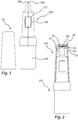
- the Figs. 1 and 2 show a liquid dispenser 100 according to the invention.
- This comprises a main unit 102 in which a liquid reservoir 104, a conveying device 106 and a discharge opening 108 are provided.
- the delivery device 106 is provided for guiding liquid from the liquid reservoir 104 to the discharge opening 108.
- Various technical designs are conceivable here, in particular a design of the dispenser with a Pressure accumulator 104 and a delivery device 106 designed as a switching valve.As soon as a user presses an actuating button 107, the switching valve is opened and the liquid under pressure in the liquid reservoir 104 flows to the discharge opening 108.
- the delivery device 106 can be designed as a pumping device 106.
- the liquid in the liquid reservoir 104 is stored without pressure and is pumped to the discharge opening 108 by actuating the pumping device 106 by means of the actuating button 107.
- the liquid dispenser of the Figs. 1 and 2 is a drop dispenser and as such has a drop formation geometry 110 surrounding the discharge opening 108, for example a planar or concave annular surface to which a drop can adhere in an overhead position of the dispenser until it detaches itself from the drop formation geometry 110 due to gravity.
- a drop formation geometry 110 surrounding the discharge opening 108, for example a planar or concave annular surface to which a drop can adhere in an overhead position of the dispenser until it detaches itself from the drop formation geometry 110 due to gravity.
- the liquid dispenser 100 has a protective cap 10, which is designed as a ventilated protective cap.
- a cap interior 14 is connected to a surrounding atmosphere via a ventilation opening 16 which, in the case of the configuration of this exemplary embodiment, is provided on an end face of the cap wall 12 of the protective cap 10.
- the ventilation opening 16 is provided with a surface structure 18, which is a flexible surface structure which is composed of several flexible layers with different properties, as will be explained below.
- the exemplary surface structure 18 shown has two layers, of which an inner layer 22 is designed as an absorbent pad and is able, after the protective cap 10 has been placed on the main unit 102, to absorb a residual drop remaining in the area of the drop formation geometry 110 and, if necessary, through an antibacterial design therein kill germs contained.
- the side of the surface structure 18 facing away from the discharge opening 108 is formed by an outer layer 20, which can be designed as a sterile filter, for example, so that germs are prevented from entering the interior of the cap 14 when the protective cap 10 is in place.
- FIGS 3A to 3C show three variants of the protective cap 10, of which the variants of Figures 3A and 3C are explained in more detail below with regard to their respective production.
- the protective cap 10 When designing according to Figure 3A the protective cap 10 has a base body 8 which forms both the jacket surfaces of the protective cap 10 and a support structure 24 which forms the ventilation opening 16 is provided surrounding it, and which extends over the surface structure 18 on both sides and thus secures the two layers 20, 22.
- the layers 20, 22 are not firmly connected to one another.
- a slight distance between the layers 20, 22 is shown to illustrate this.
- the layers 20, 22 will rest against one another at least in their edge regions 20A, 22A, in particular, however, completely. However, at least in a central area, they are not directly connected to one another and, as will be explained below, are usually not connected to one another before being attached to the base body of the protective cap. Only in the assembled state, for example in Figure 3A is shown, the layers 20, 22 are secured to one another by the support structure 24.
- the support structure 24 is configured differently, since it extends only on one side, in the present case below the surface structure 18, over its edge region 18A. Above the surface structure 18, however, the support structure 24 does not protrude beyond the layers 20, 22. Instead, the layers 20, 22, but in particular the outer layer 20, are attached to the base body 8 of the protective cap in that the latter is injection-molded onto the layer 20 previously placed in a cavity, with an edge region 20A the layer 20 is firmly connected to the base body 8.
- a special feature of the design of the Figure 3C consists of a protective structure 29 designed as a separate component, which is pushed into the ventilation opening 16 on the outside and holds there with a force fit.
- This protective structure protects the surface structure and in particular prevents damage to a layer acting as a sterile filter.
- the protective structure 29 is only exemplary in the design of the Figure 3C and could also be provided for the other cap designs described here.
- the Figures 4A to 4D show in terms of the designs of the Figures 3A and 3C two different designs each.
- the designs of the Figures 4A and 4C correspond to those of Figures 3A and 3C .
- the variant of the Figure 4B shows a design in which a ventilation insert 34, which in turn has the ventilation opening 16 and the surface structure 18, is attached at the end of a main component 32 of the protective cap 10, which in particular also forms the jacket walls.
- the ventilation insert 34 is fastened in the main component 32 of the protective cap 10 by means of a press fit.
- Alternative fastenings such as adhesive connections, welded connections and threaded connections are also possible here.
- a separate ventilation insert 34 is provided, which provides the support structure 26 with the fastening surface 28 and which is in the same way as the ventilation insert 34 of FIG Figure 4B is inserted into the main component 32 of the protective cap 10 by means of a press fit.
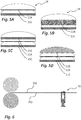
- the Figures 5A to 5D illustrate different configurations of individual layers which together form the surface structure 18. Since it is provided according to the invention that the layers of the surface structure are not connected to one another or at least not connected in a central area, it is advantageously possible to easily provide special combinations of layers for special applications. A technically complex and economical production of a composite tape from which the surface structure is removed only in the case of large numbers is therefore not necessary.
- the configurations shown here as an example each have a sterile filter.
- the separation limit of these sterile filters is preferably a maximum of 1 ⁇ m, preferably a maximum of 0.5 ⁇ m. An even finer separation limit of a maximum of 0.5 ⁇ m can also be advantageous.
- the Figure 5A shows a design in which a sterile filter 21A and an absorbent layer 21C together form the surface structure 18.
- the sterile filter 21A is shown very thin in order to make it clear that in this case it is a membrane filter, i.e. a filter that comprises a large number of pores, each of which is smaller than a predetermined separation limit, so that certain components such as bacteria are not to let through.
- a sterile filter 21B is also provided.
- this is designed as a depth filter. This means that although not every single pore of the filter is smaller than the intended separation limit, the filter is nevertheless able, due to its thickness, to reliably filter out components which are larger than the separation limit.
- a privacy protection layer 21E is provided in addition to a sterile filter 21A and an absorbent pad 21C. This primarily fulfills the function of concealing the sterile filter 21A. Since the sterile filter 21A usually has a different color than the rest of the protective cap 10, it has been found that users erroneously assume that the sterile filter 21A should be removed when the dispenser is started up. The presence of a clearly differently colored sterile filter 21A is concealed by the mentioned visual protection layer 21E, which is otherwise designed in the same color as the protective cap 10, so that the user does not get the idea of damaging the surface structure 18.
- a sterile filter layer 21A and an absorbent layer 21C for receiving a residual drop are again provided.
- a support layer 21D is still provided, which is comparatively solid and thus mechanically protects the sterile filter 21A against accidental or willful injuries.
- FIGS Figure 3A and 4A show a first method for producing a protective cap of the type described, in this case the protective cap that is also used in FIGS Figure 3A and 4A is shown.
- FIG. 6 the basic structure is shown schematically. Two strips 220, 222 are fed to a combined punching and injection molding tool 70.
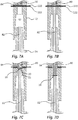
- the Figures 7A to 7H show the processing of these strips 220, 222 and the production of the protective cap 10 in the area of this punching and injection molding tool 70.
- Figure 7A shows an initial state.
- a cavity 90 which is primarily delimited by an upper shell 72 and a lower shell 74, is still open.
- the belts 220, 222 described above are inserted into two slots in the upper shell 72.
- the lower shell 74 is provided centrally with a vertically displaceable punch 82 in an opening in the lower shell 74.
- the upper shell 72 is provided with a likewise vertically displaceable punch 80 and a cutting contour 84 that is movable independently of this and that surrounds the punch 80.
- the punch 80 and the cutting contour 84 are arranged in an opening in the upper shell 72.
- the punch 82 is first moved vertically from the bottom to the top until it rests on the underside of the lower track 222.
- the upper punch 80 and the cutting contour 84 press simultaneously from above onto the band 220, so that the bands 220, 222 are pressed against one another. It arises the state of the Figure 7B one.
- the punches 80, 82 and the cutting contour 84 then move vertically downwards together, whereby the surface structure 18 consisting of two layers 20, 22 is separated from the surrounding strips 220, 222 by the cutting contour 84 at the edge of the opening in the Upper shell 72 shears off.
- the punches 80, 82 and the cutting contour 84 move together down to the position shown in Figure 7D is shown.
- the punches 80, 82 move a little further, while the lower shell 74 and the upper shell 72 are moved towards one another at the same time or separately therefrom, so that the cavity 90 is closed.
- the cutting contour 84 is no longer moved, so that for the first time there is a relative displacement between the cutting contour 84 and the punch 80.
- the cutting contour 84 remains further up and thus forms part of the delimiting wall of the cavity 90 with its end face pointing downwards.
- the step mentioned, in which the punches 80, 82 are displaced relative to the cutting contour is regarded as advantageous, it is not mandatory.
- the design of the Figure 3B can be generated by means of a method which is largely the same as the method described here, but does not provide for the aforementioned relative displacement.
- a tool can be provided in which the cutting contour 84 and the punch 80 are designed as a common component.
- liquid plastic for example PP or HDPE
- PP or HDPE is then fed into the cavity 90 through a feed opening (not shown), as in FIG Figure 7F can be seen.
- the plastic 92 hardens in the cavity 90, so that subsequently in the through the Figures 7G and 7H As illustrated, after the lower shell 74 and the upper shell 72 have been spaced apart, the finished protective cap 10 can be removed.
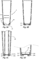
- FIG. 8A through 8D An alternative method is in the Figures 8A through 8D shown. This method is based on a base body 8 of the protective cap 10 which has already been manufactured by injection molding and in which a ventilation opening 16 is provided on the end face. This breaks through a support structure 26 which is primarily formed by a fastening surface 28.
- the two layers 20, 22 of the surface structure 18 are inserted individually into this base body 8. These are not permanently connected to each other at this point, but can of course deviate from Figure 8A be introduced in already superimposed form.
- the two layers 20, 22 have an area which is larger than the cross-sectional area of the ventilation opening 16, so that they come to rest on the fastening surface 28, such as Figure 8B shows.
- a heated die 86 is then inserted into the base body 8 from above.
- the annular end face of the die is used to press the edge regions 20A, 22A of the layers 20, 22 against the fastening surface 28 and thereby thermally connect them to one another and to the fastening surface 28.
- the result is the two-layer structure that is used in Figure 8D can be seen.
- FIG. 9A through 9F An alternative method to this arises from the Figures 9A through 9F .
- the two layers 20, 22 are inserted one after the other.
- a first layer 20 is first placed on the fastening surface 28 and thermally fastened there by means of the die 86. Only then is the second layer 22 introduced, which is then passed through Figure 9E The illustrated manner is also attached by means of the heated die 86, namely on the previously attached layer 20.
Landscapes
- Health & Medical Sciences (AREA)
- Engineering & Computer Science (AREA)
- Mechanical Engineering (AREA)
- Life Sciences & Earth Sciences (AREA)
- Animal Behavior & Ethology (AREA)
- General Health & Medical Sciences (AREA)
- Public Health (AREA)
- Veterinary Medicine (AREA)
- Chemical & Material Sciences (AREA)
- Pharmacology & Pharmacy (AREA)
- Biomedical Technology (AREA)
- Heart & Thoracic Surgery (AREA)
- Hematology (AREA)
- Manufacturing & Machinery (AREA)
- Chemical Kinetics & Catalysis (AREA)
- Anesthesiology (AREA)
- Dispersion Chemistry (AREA)
- Vascular Medicine (AREA)
- Ophthalmology & Optometry (AREA)
- Closures For Containers (AREA)
Priority Applications (4)
| Application Number | Priority Date | Filing Date | Title |
|---|---|---|---|
| EP19171379.1A EP3730101B1 (fr) | 2019-04-26 | 2019-04-26 | Capuchon de protection ventilé pour un distributeur de liquide |
| JP2020071480A JP7550528B2 (ja) | 2019-04-26 | 2020-04-13 | 液体ディスペンサーのための通気式保護キャップ、特に保護キャップのための通気インサート、かかる保護キャップ又は通気インサートを持つ液体ディスペンサー、及び保護キャップ又は通気インサートの製造方法 |
| US16/857,964 US11618618B2 (en) | 2019-04-26 | 2020-04-24 | Vented protective cap for a liquid dispenser, venting insert, in particular for a protective cap, liquid dispenser having such a protective cap or such a venting insert, and method for producing a protective cap or a venting insert |
| CN202010333927.2A CN111840065B (zh) | 2019-04-26 | 2020-04-24 | 排气式保护帽和排气插入件以及其生产方法 |
Applications Claiming Priority (1)
| Application Number | Priority Date | Filing Date | Title |
|---|---|---|---|
| EP19171379.1A EP3730101B1 (fr) | 2019-04-26 | 2019-04-26 | Capuchon de protection ventilé pour un distributeur de liquide |
Publications (2)
| Publication Number | Publication Date |
|---|---|
| EP3730101A1 true EP3730101A1 (fr) | 2020-10-28 |
| EP3730101B1 EP3730101B1 (fr) | 2024-08-21 |
Family
ID=66597469
Family Applications (1)
| Application Number | Title | Priority Date | Filing Date |
|---|---|---|---|
| EP19171379.1A Active EP3730101B1 (fr) | 2019-04-26 | 2019-04-26 | Capuchon de protection ventilé pour un distributeur de liquide |
Country Status (4)
| Country | Link |
|---|---|
| US (1) | US11618618B2 (fr) |
| EP (1) | EP3730101B1 (fr) |
| JP (1) | JP7550528B2 (fr) |
| CN (1) | CN111840065B (fr) |
Families Citing this family (3)
| Publication number | Priority date | Publication date | Assignee | Title |
|---|---|---|---|---|
| USD1054024S1 (en) * | 2021-06-24 | 2024-12-10 | Sanofi | Assembly tool |
| CN121913229A (zh) * | 2021-11-19 | 2026-04-24 | 西尔格定量泵(海默)有限公司 | 用于分配器的带通气口的帽及其使用方法 |
| EP4338774A1 (fr) * | 2022-09-16 | 2024-03-20 | Aptar Radolfzell GmbH | Tête de distribution pour un distributeur de liquide et distributeur de liquide doté d'une telle tête de distribution |
Citations (4)
| Publication number | Priority date | Publication date | Assignee | Title |
|---|---|---|---|---|
| DE1218305B (de) * | 1963-11-14 | 1966-06-02 | Soc D Verreries Ind Reunies Du | Stopfen zum Verschliessen von Faessern und anderen Behaeltern |
| US6174576B1 (en) * | 1998-02-12 | 2001-01-16 | Van De Ponseele Joseph | Permeable element, bag and cover means |
| DE102013226253B4 (de) | 2013-12-17 | 2016-03-24 | Aptar Radolfzell Gmbh | Schutzkappe für einen Spender und Spender zum Austrag von pharmazeutischen und/oder kosmetischen Flüssigkeiten |
| DE102016210992B3 (de) * | 2016-06-20 | 2017-05-11 | Aptar Radolfzell Gmbh | Flüssigkeitsspender |
Family Cites Families (13)
| Publication number | Priority date | Publication date | Assignee | Title |
|---|---|---|---|---|
| JP4405775B2 (ja) | 2003-10-09 | 2010-01-27 | 大成化工株式会社 | フィルター付き吐出容器 |
| FR2937018B1 (fr) * | 2008-10-15 | 2012-06-01 | Rexam Pharma La Verpilliere | Dispositif de distribution de liquide muni d'un organe d'etancheite deplacable sous l'effet de la pression d'un utilisateur |
| IN2012DN01794A (fr) * | 2009-09-03 | 2015-06-05 | Vito | |
| KR101221314B1 (ko) * | 2010-10-19 | 2013-01-10 | 김준배 | 약액 적하용기 |
| DE102011086755A1 (de) * | 2011-11-21 | 2013-05-23 | Aptar Radolfzell Gmbh | Spender zum Austrag von pharmazeutischen Flüssigkeiten |
| ES2569244T3 (es) * | 2011-11-25 | 2016-05-09 | Hoffmann Neopac Ag | Pitorro de tubo de distribución de gotas con un inserto |
| FR2988015B1 (fr) * | 2012-03-19 | 2015-12-11 | Rexam Healthcare La Verpillier | Dispositif de distribution de liquide muni d'un capuchon amovible |
| DE102012214426B3 (de) | 2012-08-14 | 2013-08-01 | Aptar Radolfzell Gmbh | Tropfenspender |
| DE102013215294A1 (de) * | 2013-08-02 | 2015-02-05 | GEMÜ Gebr. Müller Apparatebau GmbH & Co. KG | Membrananordnung für eine Ventileinrichtung |
| US9669974B2 (en) * | 2013-12-17 | 2017-06-06 | Aptar Radolfzell Gmbh | Protective cap for a dispenser, and discharge device for discharging pharmaceutical and/or cosmetical liquids |
| DE202015103406U1 (de) * | 2015-06-29 | 2015-07-15 | Sartorius Stedim Biotech Gmbh | Verbindungssystem |
| FR3067011B1 (fr) * | 2017-05-31 | 2019-08-02 | Nemera La Verpilliere | Embout et dispositif de distribution de liquide comprenant un capuchon |
| JP6347904B1 (ja) * | 2017-08-16 | 2018-06-27 | 株式会社悠心 | シート状ノズルキャップ |
-
2019
- 2019-04-26 EP EP19171379.1A patent/EP3730101B1/fr active Active
-
2020
- 2020-04-13 JP JP2020071480A patent/JP7550528B2/ja active Active
- 2020-04-24 US US16/857,964 patent/US11618618B2/en active Active
- 2020-04-24 CN CN202010333927.2A patent/CN111840065B/zh active Active
Patent Citations (4)
| Publication number | Priority date | Publication date | Assignee | Title |
|---|---|---|---|---|
| DE1218305B (de) * | 1963-11-14 | 1966-06-02 | Soc D Verreries Ind Reunies Du | Stopfen zum Verschliessen von Faessern und anderen Behaeltern |
| US6174576B1 (en) * | 1998-02-12 | 2001-01-16 | Van De Ponseele Joseph | Permeable element, bag and cover means |
| DE102013226253B4 (de) | 2013-12-17 | 2016-03-24 | Aptar Radolfzell Gmbh | Schutzkappe für einen Spender und Spender zum Austrag von pharmazeutischen und/oder kosmetischen Flüssigkeiten |
| DE102016210992B3 (de) * | 2016-06-20 | 2017-05-11 | Aptar Radolfzell Gmbh | Flüssigkeitsspender |
Also Published As
| Publication number | Publication date |
|---|---|
| JP7550528B2 (ja) | 2024-09-13 |
| US11618618B2 (en) | 2023-04-04 |
| JP2020183282A (ja) | 2020-11-12 |
| CN111840065B (zh) | 2024-11-26 |
| US20200339315A1 (en) | 2020-10-29 |
| CN111840065A (zh) | 2020-10-30 |
| EP3730101B1 (fr) | 2024-08-21 |
Similar Documents
| Publication | Publication Date | Title |
|---|---|---|
| DE68905881T2 (de) | Verfahren zum herstellen von beutelspendern, entsprechende teile und spender. | |
| DE68905656T2 (de) | Geneigt-spray-aerosol-antriebskopf und matrizen. | |
| DE69811305T2 (de) | Ausgabekopf mit Luftaufnahme, und mit einem solchen Kopf ausgestattete Verpackungs- und Ausgabeeinheit | |
| DE69308489T2 (de) | Flüssigkeitsauftragegerät mit zerbrechlicher Ampulle und Gehäuse | |
| DE69715476T2 (de) | Vorrichtung zur biphasischen abgabe einer einzeldosis | |
| EP1321160A2 (fr) | Méthode et distributeur pour mélange et distribution de substances | |
| DE102008014878A1 (de) | Doppelwandiger Becher | |
| EP3730101B1 (fr) | Capuchon de protection ventilé pour un distributeur de liquide | |
| DE102016210992B3 (de) | Flüssigkeitsspender | |
| WO2014202278A1 (fr) | Distributeur pour liquides | |
| DE3346351C2 (fr) | ||
| EP2089084B1 (fr) | Garniture pour seringue ou ampoule | |
| DE1284045B (de) | Injektionsspritze | |
| DE102010013543B3 (de) | Austragvorrichtung für Flüssigkeiten | |
| EP3730220B1 (fr) | Distributeur destiné à la sortie des liquides pharmaceutiques | |
| EP3275558B1 (fr) | Ensemble de pulverisation et distributeur comprenant un tel ensemble de pulverisation et tete distributrice pour un tel distributeur | |
| EP3441324B1 (fr) | Distributeur de liquide permettant de distribuer un liquide pourvu d'un réservoir supplémentaire pour un milieu supplémentaire | |
| DE3719252C2 (de) | Spender zur Ausgabe pastöser Massen | |
| DE2425951B2 (de) | Einstueckig ausgebildeter spruehkopf fuer eine aerosol-druckdose und form zu seiner herstellung | |
| WO2023213455A1 (fr) | Tête de distribution pour liquides pharmaceutiques ou cosmétiques | |
| EP4190192A1 (fr) | Distributeur de liquide et cartouches de liquide pour un tel distributeur de liquide | |
| EP2955011B1 (fr) | Procédé et dispositif de fabrication d'un gobelet | |
| EP3730219B1 (fr) | Distributeur destiné à la sortie des liquides pharmaceutiques | |
| WO2005090168A1 (fr) | Procede pour produire un emballage composite carton/matiere plastique pourvu d'un element verseur et emballage produit selon ce procede | |
| WO2012167781A1 (fr) | Procédé de fabrication d'emballages tubulaires |
Legal Events
| Date | Code | Title | Description |
|---|---|---|---|
| PUAI | Public reference made under article 153(3) epc to a published international application that has entered the european phase |
Free format text: ORIGINAL CODE: 0009012 |
|
| STAA | Information on the status of an ep patent application or granted ep patent |
Free format text: STATUS: THE APPLICATION HAS BEEN PUBLISHED |
|
| AK | Designated contracting states |
Kind code of ref document: A1 Designated state(s): AL AT BE BG CH CY CZ DE DK EE ES FI FR GB GR HR HU IE IS IT LI LT LU LV MC MK MT NL NO PL PT RO RS SE SI SK SM TR |
|
| AX | Request for extension of the european patent |
Extension state: BA ME |
|
| STAA | Information on the status of an ep patent application or granted ep patent |
Free format text: STATUS: REQUEST FOR EXAMINATION WAS MADE |
|
| 17P | Request for examination filed |
Effective date: 20201127 |
|
| RBV | Designated contracting states (corrected) |
Designated state(s): AL AT BE BG CH CY CZ DE DK EE ES FI FR GB GR HR HU IE IS IT LI LT LU LV MC MK MT NL NO PL PT RO RS SE SI SK SM TR |
|
| GRAP | Despatch of communication of intention to grant a patent |
Free format text: ORIGINAL CODE: EPIDOSNIGR1 |
|
| STAA | Information on the status of an ep patent application or granted ep patent |
Free format text: STATUS: GRANT OF PATENT IS INTENDED |
|
| RIC1 | Information provided on ipc code assigned before grant |
Ipc: B65D 47/18 20060101ALI20240304BHEP Ipc: B65D 51/16 20060101ALI20240304BHEP Ipc: A61F 9/00 20060101AFI20240304BHEP |
|
| INTG | Intention to grant announced |
Effective date: 20240319 |
|
| GRAS | Grant fee paid |
Free format text: ORIGINAL CODE: EPIDOSNIGR3 |
|
| GRAA | (expected) grant |
Free format text: ORIGINAL CODE: 0009210 |
|
| STAA | Information on the status of an ep patent application or granted ep patent |
Free format text: STATUS: THE PATENT HAS BEEN GRANTED |
|
| AK | Designated contracting states |
Kind code of ref document: B1 Designated state(s): AL AT BE BG CH CY CZ DE DK EE ES FI FR GB GR HR HU IE IS IT LI LT LU LV MC MK MT NL NO PL PT RO RS SE SI SK SM TR |
|
| REG | Reference to a national code |
Ref country code: GB Ref legal event code: FG4D Free format text: NOT ENGLISH |
|
| REG | Reference to a national code |
Ref country code: CH Ref legal event code: EP |
|
| P01 | Opt-out of the competence of the unified patent court (upc) registered |
Free format text: CASE NUMBER: APP_44149/2024 Effective date: 20240730 |
|
| REG | Reference to a national code |
Ref country code: DE Ref legal event code: R096 Ref document number: 502019011918 Country of ref document: DE |
|
| REG | Reference to a national code |
Ref country code: IE Ref legal event code: FG4D Free format text: LANGUAGE OF EP DOCUMENT: GERMAN |
|
| REG | Reference to a national code |
Ref country code: LT Ref legal event code: MG9D |
|
| REG | Reference to a national code |
Ref country code: NL Ref legal event code: MP Effective date: 20240821 |
|
| PG25 | Lapsed in a contracting state [announced via postgrant information from national office to epo] |
Ref country code: NO Free format text: LAPSE BECAUSE OF FAILURE TO SUBMIT A TRANSLATION OF THE DESCRIPTION OR TO PAY THE FEE WITHIN THE PRESCRIBED TIME-LIMIT Effective date: 20241121 |
|
| PG25 | Lapsed in a contracting state [announced via postgrant information from national office to epo] |
Ref country code: NL Free format text: LAPSE BECAUSE OF FAILURE TO SUBMIT A TRANSLATION OF THE DESCRIPTION OR TO PAY THE FEE WITHIN THE PRESCRIBED TIME-LIMIT Effective date: 20240821 Ref country code: PL Free format text: LAPSE BECAUSE OF FAILURE TO SUBMIT A TRANSLATION OF THE DESCRIPTION OR TO PAY THE FEE WITHIN THE PRESCRIBED TIME-LIMIT Effective date: 20240821 Ref country code: FI Free format text: LAPSE BECAUSE OF FAILURE TO SUBMIT A TRANSLATION OF THE DESCRIPTION OR TO PAY THE FEE WITHIN THE PRESCRIBED TIME-LIMIT Effective date: 20240821 Ref country code: GR Free format text: LAPSE BECAUSE OF FAILURE TO SUBMIT A TRANSLATION OF THE DESCRIPTION OR TO PAY THE FEE WITHIN THE PRESCRIBED TIME-LIMIT Effective date: 20241122 Ref country code: PT Free format text: LAPSE BECAUSE OF FAILURE TO SUBMIT A TRANSLATION OF THE DESCRIPTION OR TO PAY THE FEE WITHIN THE PRESCRIBED TIME-LIMIT Effective date: 20241223 |
|
| PG25 | Lapsed in a contracting state [announced via postgrant information from national office to epo] |
Ref country code: BG Free format text: LAPSE BECAUSE OF FAILURE TO SUBMIT A TRANSLATION OF THE DESCRIPTION OR TO PAY THE FEE WITHIN THE PRESCRIBED TIME-LIMIT Effective date: 20240821 |
|
| PG25 | Lapsed in a contracting state [announced via postgrant information from national office to epo] |
Ref country code: LV Free format text: LAPSE BECAUSE OF FAILURE TO SUBMIT A TRANSLATION OF THE DESCRIPTION OR TO PAY THE FEE WITHIN THE PRESCRIBED TIME-LIMIT Effective date: 20240821 |
|
| PG25 | Lapsed in a contracting state [announced via postgrant information from national office to epo] |
Ref country code: IS Free format text: LAPSE BECAUSE OF FAILURE TO SUBMIT A TRANSLATION OF THE DESCRIPTION OR TO PAY THE FEE WITHIN THE PRESCRIBED TIME-LIMIT Effective date: 20241221 |
|
| PG25 | Lapsed in a contracting state [announced via postgrant information from national office to epo] |
Ref country code: HR Free format text: LAPSE BECAUSE OF FAILURE TO SUBMIT A TRANSLATION OF THE DESCRIPTION OR TO PAY THE FEE WITHIN THE PRESCRIBED TIME-LIMIT Effective date: 20240821 |
|
| PG25 | Lapsed in a contracting state [announced via postgrant information from national office to epo] |
Ref country code: RS Free format text: LAPSE BECAUSE OF FAILURE TO SUBMIT A TRANSLATION OF THE DESCRIPTION OR TO PAY THE FEE WITHIN THE PRESCRIBED TIME-LIMIT Effective date: 20241121 Ref country code: ES Free format text: LAPSE BECAUSE OF FAILURE TO SUBMIT A TRANSLATION OF THE DESCRIPTION OR TO PAY THE FEE WITHIN THE PRESCRIBED TIME-LIMIT Effective date: 20240821 |
|
| PG25 | Lapsed in a contracting state [announced via postgrant information from national office to epo] |
Ref country code: RS Free format text: LAPSE BECAUSE OF FAILURE TO SUBMIT A TRANSLATION OF THE DESCRIPTION OR TO PAY THE FEE WITHIN THE PRESCRIBED TIME-LIMIT Effective date: 20241121 Ref country code: PT Free format text: LAPSE BECAUSE OF FAILURE TO SUBMIT A TRANSLATION OF THE DESCRIPTION OR TO PAY THE FEE WITHIN THE PRESCRIBED TIME-LIMIT Effective date: 20241223 Ref country code: PL Free format text: LAPSE BECAUSE OF FAILURE TO SUBMIT A TRANSLATION OF THE DESCRIPTION OR TO PAY THE FEE WITHIN THE PRESCRIBED TIME-LIMIT Effective date: 20240821 Ref country code: NO Free format text: LAPSE BECAUSE OF FAILURE TO SUBMIT A TRANSLATION OF THE DESCRIPTION OR TO PAY THE FEE WITHIN THE PRESCRIBED TIME-LIMIT Effective date: 20241121 Ref country code: NL Free format text: LAPSE BECAUSE OF FAILURE TO SUBMIT A TRANSLATION OF THE DESCRIPTION OR TO PAY THE FEE WITHIN THE PRESCRIBED TIME-LIMIT Effective date: 20240821 Ref country code: LV Free format text: LAPSE BECAUSE OF FAILURE TO SUBMIT A TRANSLATION OF THE DESCRIPTION OR TO PAY THE FEE WITHIN THE PRESCRIBED TIME-LIMIT Effective date: 20240821 Ref country code: IS Free format text: LAPSE BECAUSE OF FAILURE TO SUBMIT A TRANSLATION OF THE DESCRIPTION OR TO PAY THE FEE WITHIN THE PRESCRIBED TIME-LIMIT Effective date: 20241221 Ref country code: HR Free format text: LAPSE BECAUSE OF FAILURE TO SUBMIT A TRANSLATION OF THE DESCRIPTION OR TO PAY THE FEE WITHIN THE PRESCRIBED TIME-LIMIT Effective date: 20240821 Ref country code: GR Free format text: LAPSE BECAUSE OF FAILURE TO SUBMIT A TRANSLATION OF THE DESCRIPTION OR TO PAY THE FEE WITHIN THE PRESCRIBED TIME-LIMIT Effective date: 20241122 Ref country code: FI Free format text: LAPSE BECAUSE OF FAILURE TO SUBMIT A TRANSLATION OF THE DESCRIPTION OR TO PAY THE FEE WITHIN THE PRESCRIBED TIME-LIMIT Effective date: 20240821 Ref country code: ES Free format text: LAPSE BECAUSE OF FAILURE TO SUBMIT A TRANSLATION OF THE DESCRIPTION OR TO PAY THE FEE WITHIN THE PRESCRIBED TIME-LIMIT Effective date: 20240821 Ref country code: BG Free format text: LAPSE BECAUSE OF FAILURE TO SUBMIT A TRANSLATION OF THE DESCRIPTION OR TO PAY THE FEE WITHIN THE PRESCRIBED TIME-LIMIT Effective date: 20240821 |
|
| PG25 | Lapsed in a contracting state [announced via postgrant information from national office to epo] |
Ref country code: SM Free format text: LAPSE BECAUSE OF FAILURE TO SUBMIT A TRANSLATION OF THE DESCRIPTION OR TO PAY THE FEE WITHIN THE PRESCRIBED TIME-LIMIT Effective date: 20240821 Ref country code: DK Free format text: LAPSE BECAUSE OF FAILURE TO SUBMIT A TRANSLATION OF THE DESCRIPTION OR TO PAY THE FEE WITHIN THE PRESCRIBED TIME-LIMIT Effective date: 20240821 Ref country code: RO Free format text: LAPSE BECAUSE OF FAILURE TO SUBMIT A TRANSLATION OF THE DESCRIPTION OR TO PAY THE FEE WITHIN THE PRESCRIBED TIME-LIMIT Effective date: 20240821 |
|
| PG25 | Lapsed in a contracting state [announced via postgrant information from national office to epo] |
Ref country code: EE Free format text: LAPSE BECAUSE OF FAILURE TO SUBMIT A TRANSLATION OF THE DESCRIPTION OR TO PAY THE FEE WITHIN THE PRESCRIBED TIME-LIMIT Effective date: 20240821 |
|
| PG25 | Lapsed in a contracting state [announced via postgrant information from national office to epo] |
Ref country code: CZ Free format text: LAPSE BECAUSE OF FAILURE TO SUBMIT A TRANSLATION OF THE DESCRIPTION OR TO PAY THE FEE WITHIN THE PRESCRIBED TIME-LIMIT Effective date: 20240821 |
|
| PG25 | Lapsed in a contracting state [announced via postgrant information from national office to epo] |
Ref country code: SK Free format text: LAPSE BECAUSE OF FAILURE TO SUBMIT A TRANSLATION OF THE DESCRIPTION OR TO PAY THE FEE WITHIN THE PRESCRIBED TIME-LIMIT Effective date: 20240821 |
|
| REG | Reference to a national code |
Ref country code: DE Ref legal event code: R097 Ref document number: 502019011918 Country of ref document: DE |
|
| PLBE | No opposition filed within time limit |
Free format text: ORIGINAL CODE: 0009261 |
|
| STAA | Information on the status of an ep patent application or granted ep patent |
Free format text: STATUS: NO OPPOSITION FILED WITHIN TIME LIMIT |
|
| PGFP | Annual fee paid to national office [announced via postgrant information from national office to epo] |
Ref country code: DE Payment date: 20250423 Year of fee payment: 7 |
|
| PGFP | Annual fee paid to national office [announced via postgrant information from national office to epo] |
Ref country code: GB Payment date: 20250423 Year of fee payment: 7 |
|
| PGFP | Annual fee paid to national office [announced via postgrant information from national office to epo] |
Ref country code: IT Payment date: 20250430 Year of fee payment: 7 |
|
| PGFP | Annual fee paid to national office [announced via postgrant information from national office to epo] |
Ref country code: FR Payment date: 20250428 Year of fee payment: 7 |
|
| PGFP | Annual fee paid to national office [announced via postgrant information from national office to epo] |
Ref country code: CH Payment date: 20250501 Year of fee payment: 7 |
|
| 26N | No opposition filed |
Effective date: 20250522 |
|
| PG25 | Lapsed in a contracting state [announced via postgrant information from national office to epo] |
Ref country code: SE Free format text: LAPSE BECAUSE OF FAILURE TO SUBMIT A TRANSLATION OF THE DESCRIPTION OR TO PAY THE FEE WITHIN THE PRESCRIBED TIME-LIMIT Effective date: 20240821 |
|
| PG25 | Lapsed in a contracting state [announced via postgrant information from national office to epo] |
Ref country code: LU Free format text: LAPSE BECAUSE OF NON-PAYMENT OF DUE FEES Effective date: 20250426 |
|
| PG25 | Lapsed in a contracting state [announced via postgrant information from national office to epo] |
Ref country code: MC Free format text: LAPSE BECAUSE OF FAILURE TO SUBMIT A TRANSLATION OF THE DESCRIPTION OR TO PAY THE FEE WITHIN THE PRESCRIBED TIME-LIMIT Effective date: 20240821 |
|
| REG | Reference to a national code |
Ref country code: BE Ref legal event code: MM Effective date: 20250430 |
|
| PG25 | Lapsed in a contracting state [announced via postgrant information from national office to epo] |
Ref country code: BE Free format text: LAPSE BECAUSE OF NON-PAYMENT OF DUE FEES Effective date: 20250430 |
|
| PG25 | Lapsed in a contracting state [announced via postgrant information from national office to epo] |
Ref country code: IE Free format text: LAPSE BECAUSE OF NON-PAYMENT OF DUE FEES Effective date: 20250426 |