EP3730158A1 - Appareil respiratoire - Google Patents
Appareil respiratoire Download PDFInfo
- Publication number
- EP3730158A1 EP3730158A1 EP20000156.8A EP20000156A EP3730158A1 EP 3730158 A1 EP3730158 A1 EP 3730158A1 EP 20000156 A EP20000156 A EP 20000156A EP 3730158 A1 EP3730158 A1 EP 3730158A1
- Authority
- EP
- European Patent Office
- Prior art keywords
- light
- ventilator
- light source
- particle filter
- light sources
- Prior art date
- Legal status (The legal status is an assumption and is not a legal conclusion. Google has not performed a legal analysis and makes no representation as to the accuracy of the status listed.)
- Granted
Links
Images




Classifications
-
- A—HUMAN NECESSITIES
- A61—MEDICAL OR VETERINARY SCIENCE; HYGIENE
- A61M—DEVICES FOR INTRODUCING MEDIA INTO, OR ONTO, THE BODY; DEVICES FOR TRANSDUCING BODY MEDIA OR FOR TAKING MEDIA FROM THE BODY; DEVICES FOR PRODUCING OR ENDING SLEEP OR STUPOR
- A61M16/00—Devices for influencing the respiratory system of patients by gas treatment, e.g. ventilators; Tracheal tubes
- A61M16/10—Preparation of respiratory gases or vapours
- A61M16/105—Filters
- A61M16/1055—Filters bacterial
-
- A—HUMAN NECESSITIES
- A61—MEDICAL OR VETERINARY SCIENCE; HYGIENE
- A61M—DEVICES FOR INTRODUCING MEDIA INTO, OR ONTO, THE BODY; DEVICES FOR TRANSDUCING BODY MEDIA OR FOR TAKING MEDIA FROM THE BODY; DEVICES FOR PRODUCING OR ENDING SLEEP OR STUPOR
- A61M16/00—Devices for influencing the respiratory system of patients by gas treatment, e.g. ventilators; Tracheal tubes
-
- A—HUMAN NECESSITIES
- A61—MEDICAL OR VETERINARY SCIENCE; HYGIENE
- A61M—DEVICES FOR INTRODUCING MEDIA INTO, OR ONTO, THE BODY; DEVICES FOR TRANSDUCING BODY MEDIA OR FOR TAKING MEDIA FROM THE BODY; DEVICES FOR PRODUCING OR ENDING SLEEP OR STUPOR
- A61M16/00—Devices for influencing the respiratory system of patients by gas treatment, e.g. ventilators; Tracheal tubes
- A61M16/10—Preparation of respiratory gases or vapours
-
- A—HUMAN NECESSITIES
- A61—MEDICAL OR VETERINARY SCIENCE; HYGIENE
- A61L—METHODS OR APPARATUS FOR STERILISING MATERIALS OR OBJECTS IN GENERAL; DISINFECTION, STERILISATION OR DEODORISATION OF AIR; CHEMICAL ASPECTS OF BANDAGES, DRESSINGS, ABSORBENT PADS OR SURGICAL ARTICLES; MATERIALS FOR BANDAGES, DRESSINGS, ABSORBENT PADS OR SURGICAL ARTICLES
- A61L2/00—Disinfection or sterilisation of materials or objects, in general; Accessories therefor
- A61L2/02—Disinfection or sterilisation of materials or objects, in general; Accessories therefor using physical processes
- A61L2/08—Radiation
-
- A—HUMAN NECESSITIES
- A61—MEDICAL OR VETERINARY SCIENCE; HYGIENE
- A61L—METHODS OR APPARATUS FOR STERILISING MATERIALS OR OBJECTS IN GENERAL; DISINFECTION, STERILISATION OR DEODORISATION OF AIR; CHEMICAL ASPECTS OF BANDAGES, DRESSINGS, ABSORBENT PADS OR SURGICAL ARTICLES; MATERIALS FOR BANDAGES, DRESSINGS, ABSORBENT PADS OR SURGICAL ARTICLES
- A61L2/00—Disinfection or sterilisation of materials or objects, in general; Accessories therefor
- A61L2/02—Disinfection or sterilisation of materials or objects, in general; Accessories therefor using physical processes
- A61L2/08—Radiation
- A61L2/084—Visible light
-
- A—HUMAN NECESSITIES
- A61—MEDICAL OR VETERINARY SCIENCE; HYGIENE
- A61L—METHODS OR APPARATUS FOR STERILISING MATERIALS OR OBJECTS IN GENERAL; DISINFECTION, STERILISATION OR DEODORISATION OF AIR; CHEMICAL ASPECTS OF BANDAGES, DRESSINGS, ABSORBENT PADS OR SURGICAL ARTICLES; MATERIALS FOR BANDAGES, DRESSINGS, ABSORBENT PADS OR SURGICAL ARTICLES
- A61L2/00—Disinfection or sterilisation of materials or objects, in general; Accessories therefor
- A61L2/02—Disinfection or sterilisation of materials or objects, in general; Accessories therefor using physical processes
- A61L2/08—Radiation
- A61L2/085—Infrared radiation
-
- A—HUMAN NECESSITIES
- A61—MEDICAL OR VETERINARY SCIENCE; HYGIENE
- A61L—METHODS OR APPARATUS FOR STERILISING MATERIALS OR OBJECTS IN GENERAL; DISINFECTION, STERILISATION OR DEODORISATION OF AIR; CHEMICAL ASPECTS OF BANDAGES, DRESSINGS, ABSORBENT PADS OR SURGICAL ARTICLES; MATERIALS FOR BANDAGES, DRESSINGS, ABSORBENT PADS OR SURGICAL ARTICLES
- A61L2/00—Disinfection or sterilisation of materials or objects, in general; Accessories therefor
- A61L2/02—Disinfection or sterilisation of materials or objects, in general; Accessories therefor using physical processes
- A61L2/08—Radiation
- A61L2/088—Radiation using photocatalysts or photosensitisers
-
- A—HUMAN NECESSITIES
- A61—MEDICAL OR VETERINARY SCIENCE; HYGIENE
- A61L—METHODS OR APPARATUS FOR STERILISING MATERIALS OR OBJECTS IN GENERAL; DISINFECTION, STERILISATION OR DEODORISATION OF AIR; CHEMICAL ASPECTS OF BANDAGES, DRESSINGS, ABSORBENT PADS OR SURGICAL ARTICLES; MATERIALS FOR BANDAGES, DRESSINGS, ABSORBENT PADS OR SURGICAL ARTICLES
- A61L2/00—Disinfection or sterilisation of materials or objects, in general; Accessories therefor
- A61L2/26—Accessories
-
- A—HUMAN NECESSITIES
- A61—MEDICAL OR VETERINARY SCIENCE; HYGIENE
- A61L—METHODS OR APPARATUS FOR STERILISING MATERIALS OR OBJECTS IN GENERAL; DISINFECTION, STERILISATION OR DEODORISATION OF AIR; CHEMICAL ASPECTS OF BANDAGES, DRESSINGS, ABSORBENT PADS OR SURGICAL ARTICLES; MATERIALS FOR BANDAGES, DRESSINGS, ABSORBENT PADS OR SURGICAL ARTICLES
- A61L9/00—Disinfection, sterilisation or deodorisation of air
- A61L9/16—Disinfection, sterilisation or deodorisation of air using physical phenomena
- A61L9/18—Radiation
-
- A—HUMAN NECESSITIES
- A61—MEDICAL OR VETERINARY SCIENCE; HYGIENE
- A61M—DEVICES FOR INTRODUCING MEDIA INTO, OR ONTO, THE BODY; DEVICES FOR TRANSDUCING BODY MEDIA OR FOR TAKING MEDIA FROM THE BODY; DEVICES FOR PRODUCING OR ENDING SLEEP OR STUPOR
- A61M16/00—Devices for influencing the respiratory system of patients by gas treatment, e.g. ventilators; Tracheal tubes
- A61M16/0057—Pumps therefor
-
- A—HUMAN NECESSITIES
- A61—MEDICAL OR VETERINARY SCIENCE; HYGIENE
- A61M—DEVICES FOR INTRODUCING MEDIA INTO, OR ONTO, THE BODY; DEVICES FOR TRANSDUCING BODY MEDIA OR FOR TAKING MEDIA FROM THE BODY; DEVICES FOR PRODUCING OR ENDING SLEEP OR STUPOR
- A61M16/00—Devices for influencing the respiratory system of patients by gas treatment, e.g. ventilators; Tracheal tubes
- A61M16/0087—Environmental safety or protection means, e.g. preventing explosion
-
- A—HUMAN NECESSITIES
- A61—MEDICAL OR VETERINARY SCIENCE; HYGIENE
- A61M—DEVICES FOR INTRODUCING MEDIA INTO, OR ONTO, THE BODY; DEVICES FOR TRANSDUCING BODY MEDIA OR FOR TAKING MEDIA FROM THE BODY; DEVICES FOR PRODUCING OR ENDING SLEEP OR STUPOR
- A61M16/00—Devices for influencing the respiratory system of patients by gas treatment, e.g. ventilators; Tracheal tubes
- A61M16/06—Respiratory or anaesthetic masks
-
- A—HUMAN NECESSITIES
- A61—MEDICAL OR VETERINARY SCIENCE; HYGIENE
- A61M—DEVICES FOR INTRODUCING MEDIA INTO, OR ONTO, THE BODY; DEVICES FOR TRANSDUCING BODY MEDIA OR FOR TAKING MEDIA FROM THE BODY; DEVICES FOR PRODUCING OR ENDING SLEEP OR STUPOR
- A61M16/00—Devices for influencing the respiratory system of patients by gas treatment, e.g. ventilators; Tracheal tubes
- A61M16/08—Bellows; Connecting tubes ; Water traps; Patient circuits
- A61M16/0816—Joints or connectors
-
- A—HUMAN NECESSITIES
- A61—MEDICAL OR VETERINARY SCIENCE; HYGIENE
- A61L—METHODS OR APPARATUS FOR STERILISING MATERIALS OR OBJECTS IN GENERAL; DISINFECTION, STERILISATION OR DEODORISATION OF AIR; CHEMICAL ASPECTS OF BANDAGES, DRESSINGS, ABSORBENT PADS OR SURGICAL ARTICLES; MATERIALS FOR BANDAGES, DRESSINGS, ABSORBENT PADS OR SURGICAL ARTICLES
- A61L2103/00—Materials or objects being the target of disinfection or sterilisation
- A61L2103/15—Laboratory, medical or dentistry appliances, e.g. catheters or sharps
-
- A—HUMAN NECESSITIES
- A61—MEDICAL OR VETERINARY SCIENCE; HYGIENE
- A61L—METHODS OR APPARATUS FOR STERILISING MATERIALS OR OBJECTS IN GENERAL; DISINFECTION, STERILISATION OR DEODORISATION OF AIR; CHEMICAL ASPECTS OF BANDAGES, DRESSINGS, ABSORBENT PADS OR SURGICAL ARTICLES; MATERIALS FOR BANDAGES, DRESSINGS, ABSORBENT PADS OR SURGICAL ARTICLES
- A61L2202/00—Aspects relating to methods or apparatus for disinfecting or sterilising materials or objects
- A61L2202/10—Apparatus features
- A61L2202/11—Apparatus for generating biocidal substances, e.g. vaporisers, UV lamps
-
- A—HUMAN NECESSITIES
- A61—MEDICAL OR VETERINARY SCIENCE; HYGIENE
- A61L—METHODS OR APPARATUS FOR STERILISING MATERIALS OR OBJECTS IN GENERAL; DISINFECTION, STERILISATION OR DEODORISATION OF AIR; CHEMICAL ASPECTS OF BANDAGES, DRESSINGS, ABSORBENT PADS OR SURGICAL ARTICLES; MATERIALS FOR BANDAGES, DRESSINGS, ABSORBENT PADS OR SURGICAL ARTICLES
- A61L2209/00—Aspects relating to disinfection, sterilisation or deodorisation of air
- A61L2209/10—Apparatus features
- A61L2209/11—Apparatus for controlling air treatment
-
- A—HUMAN NECESSITIES
- A61—MEDICAL OR VETERINARY SCIENCE; HYGIENE
- A61L—METHODS OR APPARATUS FOR STERILISING MATERIALS OR OBJECTS IN GENERAL; DISINFECTION, STERILISATION OR DEODORISATION OF AIR; CHEMICAL ASPECTS OF BANDAGES, DRESSINGS, ABSORBENT PADS OR SURGICAL ARTICLES; MATERIALS FOR BANDAGES, DRESSINGS, ABSORBENT PADS OR SURGICAL ARTICLES
- A61L2209/00—Aspects relating to disinfection, sterilisation or deodorisation of air
- A61L2209/10—Apparatus features
- A61L2209/12—Lighting means
-
- A—HUMAN NECESSITIES
- A61—MEDICAL OR VETERINARY SCIENCE; HYGIENE
- A61L—METHODS OR APPARATUS FOR STERILISING MATERIALS OR OBJECTS IN GENERAL; DISINFECTION, STERILISATION OR DEODORISATION OF AIR; CHEMICAL ASPECTS OF BANDAGES, DRESSINGS, ABSORBENT PADS OR SURGICAL ARTICLES; MATERIALS FOR BANDAGES, DRESSINGS, ABSORBENT PADS OR SURGICAL ARTICLES
- A61L2209/00—Aspects relating to disinfection, sterilisation or deodorisation of air
- A61L2209/10—Apparatus features
- A61L2209/14—Filtering means
-
- A—HUMAN NECESSITIES
- A61—MEDICAL OR VETERINARY SCIENCE; HYGIENE
- A61M—DEVICES FOR INTRODUCING MEDIA INTO, OR ONTO, THE BODY; DEVICES FOR TRANSDUCING BODY MEDIA OR FOR TAKING MEDIA FROM THE BODY; DEVICES FOR PRODUCING OR ENDING SLEEP OR STUPOR
- A61M39/00—Tubes, tube connectors, tube couplings, valves, access sites or the like, specially adapted for medical use
- A61M39/02—Access sites
- A61M39/0247—Semi-permanent or permanent transcutaneous or percutaneous access sites to the inside of the body
- A61M2039/0285—Semi-permanent or permanent transcutaneous or percutaneous access sites to the inside of the body with sterilisation means, e.g. antibacterial coatings, disinfecting pads, UV radiation LEDs or heating means in the port
-
- A—HUMAN NECESSITIES
- A61—MEDICAL OR VETERINARY SCIENCE; HYGIENE
- A61M—DEVICES FOR INTRODUCING MEDIA INTO, OR ONTO, THE BODY; DEVICES FOR TRANSDUCING BODY MEDIA OR FOR TAKING MEDIA FROM THE BODY; DEVICES FOR PRODUCING OR ENDING SLEEP OR STUPOR
- A61M2202/00—Special media to be introduced, removed or treated
- A61M2202/20—Pathogenic agents
- A61M2202/203—Bacteria
-
- A—HUMAN NECESSITIES
- A61—MEDICAL OR VETERINARY SCIENCE; HYGIENE
- A61M—DEVICES FOR INTRODUCING MEDIA INTO, OR ONTO, THE BODY; DEVICES FOR TRANSDUCING BODY MEDIA OR FOR TAKING MEDIA FROM THE BODY; DEVICES FOR PRODUCING OR ENDING SLEEP OR STUPOR
- A61M2202/00—Special media to be introduced, removed or treated
- A61M2202/20—Pathogenic agents
- A61M2202/206—Viruses
-
- A—HUMAN NECESSITIES
- A61—MEDICAL OR VETERINARY SCIENCE; HYGIENE
- A61M—DEVICES FOR INTRODUCING MEDIA INTO, OR ONTO, THE BODY; DEVICES FOR TRANSDUCING BODY MEDIA OR FOR TAKING MEDIA FROM THE BODY; DEVICES FOR PRODUCING OR ENDING SLEEP OR STUPOR
- A61M2205/00—General characteristics of the apparatus
- A61M2205/75—General characteristics of the apparatus with filters
- A61M2205/7545—General characteristics of the apparatus with filters for solid matter, e.g. microaggregates
Definitions
- a ventilator is understood to be a device controlled, for example electronically by microprocessors, which is designed to support or maintain or for therapeutic treatment, for example CPAP therapy, the respiratory function of a patient.
- This also includes ventilators that are designed as anesthesia machines and / or for ventilating patients without spontaneous breathing.
- the patient is a human or an air-breathing animal, for example a mammal.
- infectious diseases i.e. through infectious microorganisms such as fungi, fungal spores, bacteria and viruses
- pathogens i.e. through infectious microorganisms such as fungi, fungal spores, bacteria and viruses
- concentration of pathogens and thus the risk of infection is particularly high in the ambient air. People with a weakened immune system are particularly affected.
- One possible route of infection here is via the air applied or admixed by ventilators from compressed gas lines or conveyed by means of a fan from the device environment.
- ventilators including those designed as anesthesia machines, are provided with particle filters to separate pathogens as standard. Since these filters are based on the principle of size exclusion, not all pathogens can be separated. With such ventilators according to the state of the art, the risk of pneumonal infections is therefore not sufficiently averted.
- UV ultraviolet radiation
- US 2016 0271288 A1 described a device which is designed for the sterilization of air by means of UV.
- Another device for disinfecting microorganisms generally by means of polychromatic light is in US Pat WO 2017 023783 A1 disclosed.
- the polychromatic light shows this has a significant wavelength portion of ultraviolet radiation, for the generation of which a single light source is provided.
- WO 2017 023783 A1 A dichroic mirror is therefore required to divert thermal radiation and to reflect antimicrobially effective radiation back.
- WO 2014 159874 A1 teaches a UV irradiation system which comprises optical fibers introduced into medical tubes, for example a tracheal tube, for the emission of UV light.
- the WO 2012 052908 A1 also discloses a tracheal tube with such optical fibers which preferably emit electromagnetic radiation in the UV-C wavelength range.
- the WO 2015 092695 A1 comprises a ventilator, in whose pneumatic circuit system a lighting device for emitting general disinfecting light is integrated, wherein the disinfecting light is preferably given by UV and particularly preferably UV-C and is provided by light sources (LED), among other things.
- the DE 101 07 443 A1 relates to a method for disinfecting breathed air in ventilators by means of strong electromagnetic radiation within their pneumatic circuit systems, the electromagnetic radiation being given by UV or microwaves and applied in pulse form.
- the CN 204233560 U describes, on the other hand, an anesthesia device with disinfecting condensate drainage, with only the exhalation hose being sequentially connected to an exhalation check valve, a photocatalyst sterilizer and a cold trap, complementary to the aforementioned examples.
- the CN 204233560 U Although discloses the general use of UV for disinfection, it does not disclose the nature and mode of operation of the photocatalyst sterilizer.
- Light sources a light-emitting diode is mentioned as an example, are commercially available with emission ranges of different widths and emission maxima in the UV to infrared (IR) range and in almost any design and size. Light sources are inexpensive and have an optimal degree of efficiency compared to other electrical light sources.
- Each light source has an emission surface which is designed to emit light. By designing the shape of the emission surface, a light emission direction as well as the geometric emission shape of the emitted light can be set, for example as a light cone or as a fan of light.
- Light sources each emit polychromatic light over a wavelength interval and have at least one emission maximum for a certain wavelength within such a wavelength interval, each intensity profile corresponding to a Planck distribution with respect to an emission maximum.
- the object of the invention is to provide a ventilation device and / or a corresponding one which is improved in terms of hygiene and operational safety compared to the prior art To provide adapters. According to the invention, this object is achieved by the proposed ventilator with the features of claim 1 or the proposed adapter for a ventilator with the features of claim 17.
- Ventilator with a pneumatic system for conveying ventilation gas in a flow direction to a patient or from a patient, wherein the ventilation device comprises at least one light source, the at least one light source in an emission direction on the ventilation gas and / or on a display surface and / or on the pneumatic system is aligned.
- Ventilator the emitted light being selected from a first wavelength range from 385 nm to 780 nm and / or from a second wavelength range from more than 780 nm to 2000 nm.
- Ventilation device according to at least one of the preceding claims, characterized in that the light source is set up and designed to at least weaken or inactivate germs (viruses, bacteria, fungi) by means of the emitted light.
- Ventilator the pneumatic system comprising at least one air supply to the ventilator and / or a respiratory gas outlet for the patient and / or a patient interface and / or a gas flow line and / or filter.
- Ventilator the at least one light source being arranged in the area of the air supply to the ventilator and / or in the area of the patient's respiratory gas discharge and / or in the area of the patient interface and / or along the gas flow lines.
- Ventilator with a pneumatic circuit system for conveying ventilation gas in a flow direction to a patient, with at least one particle filter being arranged within the pneumatic circuit system, to which at least one light source is aligned in a light emission direction.
- the ventilator is also characterized in that the light source is arranged first in the flow direction and then the particle filter.
- the ventilator is also characterized in that light emitted onto the particle filter is selected from a first wavelength range from 385 nm to 780 nm and / or from a second wavelength range from more than 780 nm to 2000 nm.
- the ventilator is also characterized in that at least one light source is arranged on both sides of the particle filter.
- the ventilator is also characterized in that the particle filter on the side of the light source can be completely illuminated.
- the ventilator is also characterized in that the particle filter can be evenly illuminated all around.
- the ventilator is also characterized in that several types of light sources are aligned circumferentially on the particle filter in alternating order with regard to the types of light sources, the types of light sources differing in the light emitted in each case.
- the ventilator is also characterized in that there is a type of light sources which are designed to emit light with an emission maximum of 405 nm.
- the ventilator is also characterized in that the emitted light from all light sources comprises a wavelength continuum from 385 nm to 2000 nm.
- the ventilator is also characterized in that the particle filter is designed as a glass frit or as a pellet made of glass wool and / or as a filter for retaining pathogens and dust.
- the ventilator is also characterized in that a plurality of particle filters are arranged in the pneumatic circuit system, each with a decreasing pore size in the flow direction.
- Adapter for a ventilator with a pneumatic system for conveying ventilation gas comprising at least one air supply to the ventilator and / or a respiratory gas outlet for the patient and / or a patient interface and / or a gas flow line and / or filter
- the adapter with at least is equipped with a light source and can be connected to the air supply and / or the respiratory gas discharge and / or the patient interface and / or a gas flow line, wherein the at least one light source can be aligned with the ventilation gas and / or the pneumatic system and the at least one light source so is set up and designed to at least weaken or inactivate germs (viruses, bacteria, fungi) through the emitted light.
- the adapter has at least one device for slowing down the flow of the respiratory gas and / or for at least temporary accumulation and / or filtering of germs (viruses, bacteria, fungi) and the at least one light source is directed at this device.
- the at least one device is in the form of a particle filter and / or a baffle and / or a cover.
- the ventilator claimed has a pneumatic circuit system for delivering ventilation gas in a flow direction by means of a gas delivery device through a device outlet via an interface to a patient.
- the gas delivery device is provided by an electric fan for sucking in outside air or by a connection to a compressed air supply device.
- an interface is understood to mean a connection device which pneumatically connects the device outlet to the patient's respiratory organs.
- the interface is provided, for example, through a ventilation hose connected to a tracheal tube, the tracheal tube being led directly to the patient's respiratory organs.
- the ventilation hose is alternatively connected to a ventilation mask, the ventilation mask being placed around the patient's mouth and / or nose and thus connected to the patient's respiratory organs.
- the pneumatic circuit system includes all piping for the flow of ventilation gas, which are pneumatically connected to one another between the gas delivery device and the device outlet.
- the ventilating gas consists of natural or synthetic air or from natural or synthetic air enriched with additional oxygen or from pure oxygen.
- the ventilator claimed is also designed as an anesthetic device, at least one inhalation anesthetic is added to the ventilator gas, at least temporarily.
- gaseous and / or aerosolic water and / or one or more noble gases are optionally added to the ventilating gas.
- the direction of flow of the ventilation gas is set in the direction from the gas delivery device to the device outlet.
- the ventilation gas is typically delivered with a flow of up to 300 ml min -1 by means of the gas delivery device.
- At least one such particle filter is pneumatically switched within the pneumatic circuit system, to which at least one light source is aligned in a light emission direction.
- the particle filter has a front surface and a rear surface, the particle filter being pneumatically switched in the pneumatic circuit system in such a way that, when the ventilator being claimed, the flow of the ventilation gas in the flow direction first penetrates the front surface and then the rear surface of the particle filter.
- the front surface and the rear surface substantially or entirely each correspond to a flow cross section.
- a second inventive idea is therefore in the proposed ventilator realized by aligning at least one light source in a light emission direction on the particle filter in such a way that first the light source and then subsequently the particle filter is fixedly arranged in the flow direction.
- light is emitted onto the front surface of the particle filter by means of the light source. This results in irradiation of both the front surface accumulated pathogens and pathogens deposited on the front surface in the light emission direction of the light source.
- the particle filter is manufactured accordingly from an at least partially translucent material, the light emitted by the light sources can penetrate through the front surface, so that pathogens within the particle filter are also at least partially captured by irradiation.
- the light source it is by no means necessary for the light source to be attached within the piping of the pneumatic circuit system. It is only necessary that the light emission direction of the light source is aligned with the front surface of the particle filter and that irradiation of the front surface is ensured. For example, this can also be achieved by means of a sufficiently transparent light window which is let into the piping in front of the front surface of the particle filter.
- a sufficiently transparent light window is made of quartz or sapphire, for example.
- the light source is fixed on the light window in such a way that the front surface of the particle filter can be irradiated in the light emission direction.
- the proposed ventilator is based on the hierarchy of coupled quantum systems as a third inventive concept with regard to the light emitted by the light source .
- a set of different oscillator states is given for each electronic excitation state of a molecule or a molecular aggregate.
- a pathogen i.e. a virulent microorganism, corresponds in principle to a molecular aggregate.
- Is by an electronic excitation by irradiation with light in such a Molecular aggregate selected from a first wavelength range from 385 nm to 780 nm, but in particular from a first wavelength range from 385 nm to 425 nm, if the bond order of a chemical bond is reduced, this results in energetically reduced oscillator states and thus energetically reduced dissociation energies of the bond in question given a real one Morse potential.
- IR infrared radiation
- the light emitted onto the particle filter is selected from a first wavelength range from 385 nm to 780 nm (sufficient excitation of electronic states) and from a second wavelength range from more than 780 nm to 1700 nm (corresponding to an excitation of oscillator states) .
- At least one light source is arranged on both sides of the particle filter.
- at least one light source is aligned on the particle filter also on its rear surface in its light emission direction, whereby a post-treatment of pathogens penetrating the particle filter by irradiation with light is particularly advantageously possible.
- the particle filter is not only made of a translucent material, but its front and rear surfaces also have a sufficiently small distance from one another, it is also particularly advantageous if the light source has sufficient irradiation power enables irradiation over the entire distance between the rear and front surface.
- the particle filter can be completely illuminated on the side of the light source. This can already be achieved with one light source, for example, in that it is designed to emit light in the geometric shape of a light cone with a sufficiently large light cone angle. This enables all pathogens to be irradiated which, when the proposed ventilator is operated, emerge on the front surface of the particle filter and / or through its rear surface with the flow of the ventilation gas.
- the particle filter can be uniformly illuminated all around with at least one light source. This can be achieved, for example, with a single light source in that its emission surface itself is designed to be circumferential, closed in itself and angled inward. For example, a circumferential, self-contained light window is let into the piping, over which a light source with a circumferential, self-contained and inwardly angled emission surface is pushed and fixed.
- a light source with a circumferential, self-contained and inwardly angled emission surface is pushed and fixed.
- several light sources are arranged around the particle filter at equal distances from one another. Uniform illumination of the front and / or rear surface of the particle filter ensures that all pathogens that hit the particle filter or pass through the particle filter are exposed to the same or at least approximately the same radiation density of the light emitted by the light source or light sources.
- a light source which is designed, for example, to emit light in a wavelength interval of 385 nm to 1700 nm, preferably up to 2000 nm and has only a single emission maximum
- an at least approximately uniform excitation of both electron states and oscillator states can only be achieved if when the emission maximum is located between the wavelength range of the excitations of electronic states and the wavelength range of the excitations of oscillator states. For a sufficiently high excitation, this requires a light source with a very high power level.
- light sources of this type therefore preferably have both the first wavelength range of the excitations of electronic states and the second wavelength range of the excitations of oscillator states each have at least one emission maximum.
- a light source of this type has a total of at least two emission maxima over a wavelength interval from 385 nm to 2000 nm.
- the light sources In a fourth development of the invention with regard to the light sources, several types of light sources are aligned on the particle filter in an alternating sequence with regard to the types of light sources.
- the types of light sources differ in the light emitted in each case. This particularly advantageously allows the selection and combination of such light sources, the light emitted in each case with respect to the wavelength interval and / or emission maximum being matched to the excitation of electron states and / or oscillator states. It is thus also possible to specifically adapt the illumination of the particle filter with regard to the killing and / or inactivation of specific pathogens, such as MRSA, for example.
- By arranging different types of light sources circumferentially around the particle filter and in alternating sequence it is easy to achieve a uniform and complete illumination of the particle filter.
- the proposed ventilator is in no way limited to a particle filter arranged in the pneumatic circuit system, in particular to one or more particle filters of only one type.
- the proposed ventilator is in no way limited to particle filters arranged in the pneumatic circuit system, to which at least one light source is aligned in a light emission direction.
- the number and nature of the particle filters is determined solely by the size of the ventilator being used and by specifying a maximum total flow resistance of, for example, up to 5 hPa min 120 -1 L -1 .
- the particle filter is designed as a glass frit or as a pellet made of glass wool and / or for the retention of pathogens.
- a glass frit or a pellet made of glass wool can be sterilized particularly advantageously by autoclaving at more than 130 ° C and can therefore be reused.
- a type selectivity of the Particle filter can be optimized alternatively or additionally with regard to the retention of specific microorganisms.
- Particle filters of various pore sizes and made of various materials to retain particles and / or microorganisms are commercially available. Permanent retention of particles and / or microorganisms in the particle filter also improves the disinfection of the ventilation gas.
- the glass frit has a pore size of 1 ⁇ m to 200 ⁇ m, preferably 2 to 150 ⁇ m. Such a glass frit does not have any noticeable flow resistance without the accumulation of microorganisms in front of and on the front surface of the glass frit being impaired.
- a plurality of particle filters are arranged in the pneumatic circuit system. With such a combined arrangement, an optimum period of use of the particle filters is guaranteed until they have to be replaced due to saturation with particles and microbes.
- the light sources are supplied with energy via the power supply unit of the ventilator.
- the light sources are integrated into the internal power supply of the ventilator, for example. This integration also enables, for example, the operation of the light sources in the event that the ventilator is supplied with energy via a battery.
- the light sources are supplied with energy via an energy source that is external to the ventilator.
- the light sources can be connected to their own power supply unit or rechargeable batteries or batteries. Connection to an external power supply is conceivable in particular for the adapter according to the invention. A connection of the light sources to an external energy source is also conceivable in the case of light sources that are built into the ventilator.
- the light sources are switchable, ie they can be activated and deactivated.
- the light sources are connected to a switch that can interrupt the energy supply, for example, the light sources can switch off or deactivate.
- a switch is set up in such a way that (renewed) activation or switching on of the light sources is also possible.
- Such a light switch can for example be integrated into the housing of the ventilator, but can also be designed as an extra switch.
- the adapter according to the invention has, for example, a switch that is independent of the ventilator.
- the light sources are set up in such a way that their luminosity can be varied (for example by adapting the operating voltage of the light sources), that is to say can be dimmed, by a control unit which is not described in detail.
- This also means that the luminosity or the operating voltage of the light sources can be regulated down to such an extent that the light sources are switched off.
- the light sources are set up and integrated into the ventilator in such a way that they can be switched on and off by a control system of the ventilator or the light intensity can also be varied. In this way, for example, an automatic switch-off of the lamps can be set up when the ventilator is switched from mains to AC operation.
- the provision of an adapter for ventilators also offers the advantage of inexpensively upgrading ventilators without the described features of the invention with the same features.
- the proposed adapter includes the same features as the proposed ventilator and can be attached or connected to a ventilator subsequently or in addition.
- pathogens germs, and microorganisms are used as synonyms in this application in order to denote, in particular, but not exclusively, viruses, bacteria, fungi, for example.
- the ventilator 1 claimed is designed as an anesthesia machine.
- the ventilation device 1 has a pneumatic circuit system 2 for conveying ventilation gas in a flow direction d by means of an electric fan through a device outlet via an interface to a patient.
- the interface is connected to a tracheal tube via a ventilation hose, the tracheal tube being led directly to the patient's respiratory system.
- the Fig. 1 and the Fig. 2 are not to scale. In the Fig. 1 and in the Fig. 2 the electric fan, the device outlet, the interface, the patient's respiratory system and the patient are not shown.
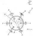
- the Fig. 1 and the Fig. 2 each schematic partial views of the claimed ventilator 1.
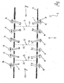
- three particle filters 31, 32 and 33 are pneumatically switched.
- Six light sources are arranged on each side of each particle filter 31, 32 and 33, the light sources including those of a first type 41, a second type 42 and a third type 43.
- the light sources 41, 42 and 43 are each aligned in a light emission direction r on the particle filters 31, 32 and 33.
- the light emission directions r are each illustrated in the form of a double arrow.
- the Fig. 1 shows the claimed ventilator 1 in a schematic partial view of a pneumatic circuit system 2 in longitudinal section.
- the one to three particle filters 31, 32 and 33 are connected pneumatically, for example in a cylindrical piping 21.
- the particle filters 31, 32 and 33 each have a front surface 310, 320 and 330 and each a rear surface 311, 321 and 331, the particle filters 31, 32 and 33 being pneumatically switched in the pneumatic circuit system 2 in such a way that
- the flow of the ventilation gas in flow direction d first penetrates the respective front surface 310, 320 and 330 and then the respective rear surface 311, 321 and 331 of the respective particle filter 31, 32 and 33.
- the flow direction d is in Fig. 1 indicated by an arrow.
- the front surfaces 310, 320 and 330 and the rear surfaces 311, 321 and 331 each substantially correspond to a flow cross section.
- a total of six light windows 22 are firmly embedded in the piping 21 via a tongue and groove connection.
- the light windows 22 are also each designed as a cylindrical tube piece, which in addition to two connecting springs on each connection side the same radius and Has jacket thickness like the piping 21.
- the thus circumferential, self-contained light windows 22 are identical in their design and are made of quartz.
- a light window 22 is arranged in front of and in each case after each particle filter 31, 32 and 33 in the flow direction d.
- Fig. 1 only the light sources of the first type 41 are visible.
- a total of six light sources 41, 42 and 43 are fixed on each light window 21 in such a way that irradiation both of the respective front surface 310, 320 and 330 as well as the rear surface 311, 321 and 331 of the relevant particle filter 31, 32 and 33 is enabled.
- the partial section of the piping 21 shown here is therefore not able to influence a laminar flow of the ventilation gas through the light sources 41, 42 and 43 due to the design.
- irradiation of the pathogens is therefore particularly advantageous due to the design, both when they accumulate in front of the front surface 310, 320 and 330 and when they pass through the rear surface 311, 321 and 331 of the particle filters 31, 32 and 33 allows.
- the particle filter 31 is designed as a glass frit 31, for example. Silver or titanium dioxide, for example, is additionally introduced into the glass frit 31, the titanium dioxide having a mass fraction of 1% platinum.
- the glass frit 31 is designed as a catalyst which accelerates the oxidation of microorganisms by photo- and thermocatalytic means; thus, in this exemplary embodiment, the decomposition, destruction and / or inactivation of microorganisms can be implemented in three mutually independent ways.
- the glass frit 31 has a pore size of 1 ⁇ m to 200 ⁇ m and thus represents a negligible flow resistance under operating conditions.
- the particle filter 32 is designed to hold back bacteria and fungi and the particle filter 33 is designed to hold back viruses.
- three particle filters 31, 32 and 33 are arranged in the pneumatic circuit system 2, with pore sizes each decreasing in the flow direction d.
- FIGs 3a and 3b an exemplary embodiment of the ventilator 1 is shown schematically in detail, in which the light sources 41, 42, 43 are arranged in such a way that the display surface 103 is irradiated.
- the light sources 41, 42, 43 are arranged, for example, in a light source housing 1031 so that the light sources are located above the display surface. It is thus possible for the emission direction r of the light sources 41, 42, 43 to strike the display surface 103.
- the light source housing 1031 comprises a type of screen 1032 which extends beyond the end of the light sources.
- This screen 1032 has the effect that although the display surface 103 can be irradiated, the light sources 41, 42, 43 do not emit in the direction of people looking at the display surface, for example.
- reflectors (not shown) are additionally mounted in the light source housing 1031 in such a way that the emission direction r of the light sources 41, 42, 43 is directed in particular onto the display surface 103.
- the display area 103 is designed as a touchscreen on which the inputs, such as variation of the ventilation pressure, are set directly on the display area 103, it is advantageous if this surface can be sterilized by the light sources.
- the Fig. 4 shows schematically a section from an exemplary embodiment of the ventilator 1, in which the light sources 41, 42, 43 are arranged inside the ventilator behind the display area 103.
- the light sources 41, 42, 43 are set up in such a way that the emission direction r shines onto the display surface from behind.
- the display area 103 is advantageously set up, for example, in such a way that the radiation shines through the display area 103 and at least reaches the surface of the display area.
- the light sources 41, 42, 43 in addition to sterilizing the surface of the display area, the light sources 41, 42, 43 also serve as background lighting for the display area 103.
- the display area 103 is designed as an LCD, for example.
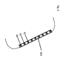
- Fig. 5 an exemplary embodiment of the ventilator 1 is shown in detail, in which the light sources 41, 42, 43 themselves are part of the display area 103.
- the light sources can be designed as organic light-emitting diodes and together result in an OLED display.
- the general advantages of an OLED display - space-saving design and low power consumption - can be combined with the sterilizing effect of the selected light sources.
- FIG. 6 to 9 Exemplary embodiments of the ventilator 1 are shown in which the light sources are arranged in the area of the breathing gas discharge 102. In addition to the examples shown, combinations with the in Fig.1 and 2 described functional principle possible. In the Fig. 1 and 2 The exemplary embodiments of the subsections described, for example, can be arranged in front of the outlet 1025 within the ventilator 1 but in the flow direction d after the patient. In the Figures 6 to 9 described embodiments relate in particular to ventilators, in which the breathing gas is fed back from the patient to the ventilator in, for example, a two-tube system and there, for example, is discharged from the ventilation system by a breathing gas discharge.
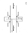
- FIGs 6a and 6b show by way of example the area of the respiratory gas outlet 102 of the ventilator 1.
- a baffle surface 1021 is arranged, for example, which covers but does not close the outlet 1025 of the respiratory gas outlet 102.
- the baffle surface 1021 is connected to the area of the breathing gas discharge 102 by connections 1024 at a distance from the outlet 1025 of the breathing gas discharge.
- the connections 1024 are arranged, for example, spaced around the output 1025. Examples are in Figure 6b three connections 1024 are shown, but more or fewer connections can also be arranged between the impact surface 1021 and the area of the breathing gas discharge 102.
- the light sources 41, 42, 43 are arranged, for example, in the area of the breathing gas discharge 102 inside the housing and around the outlet 1025.
- the light sources 41, 42, 43 can be arranged, for example, such that the individual types of light sources are arranged alternately. This means that a light source 42 can be arranged next to a light source 41 and a light source 43 can be arranged next to it. However, the order can also be structured differently as desired.
- the number of the individual types of light source does not have to be evenly distributed - for example, twice as many light sources 41 as light sources 42 and 43 can be present. Only one or two types of light sources can also be used.
- the housing of the ventilator 1 has openings or light windows that are not described in detail, so that the light sources 41, 42, 43, for example, in the direction of the impact surface. 1021 can shine.
- the area of the baffle 1021 is, for example, larger than the cross-sectional area of the outlet 1025 and completely covers the outlet, as in FIG Figure 6b to recognize schematically.
- the baffle surface 1021 is set up, for example, in such a way that the ventilation gas flows with the flow direction d in the direction of the baffle surface 1021 and in the process strikes the baffle surface 1021. On the one hand, this slows down the flow rate and, on the other hand, the pathogens or germs from the ventilation gas can also accumulate on the surface. This makes it possible to extend the radiation duration of the pathogens and leads to effective sterilization.
- the impact surface 1021 can also be coated with silver or platinum-containing titanium oxide in order to achieve additional advantageous effects, as in FIG Fig. 1 and 2 described to achieve.
- the impact surface 1021 is arranged, for example, perpendicular to the flow direction d.
- the baffle surface 1021 can also be arranged inclined to the flow direction d.
- the impact surface 1021 is designed as a structured surface.
- the baffle surface 1021 can also assume other geometric shapes such as, for example, conical, in the shape of a hemisphere or any free shape. It is also possible, for example, that the light sources 41, 42, 43 are not distributed around the output 1025, but are only arranged in places or on one side.
- an arrangement of particle filters as in FIG Fig. 1 and Fig. 2 be arranged in the area of the breathing gas discharge 102 as described.
- particle filters can also be arranged on the baffle.
- the particle filters are set up and designed to at least partially hold back germs (viruses, bacteria, fungi). In all of the exemplary embodiments, they are also set up and designed to at least partially transmit the light according to the invention or to allow it to penetrate deeper layers of the filter.
- the number and arrangement of the light sources and the baffle are mainly intended to represent the functional principle by way of example, and that both light sources and baffle are possible in various numbers, arrangements and shapes.
- FIG. 4 shows a section of an exemplary embodiment of the ventilator 1 in the area of the breathing gas discharge 102.
- the basic elements and mode of operation are as in FIG Fig. 6 described.
- further light sources 41, 42, 43 are arranged in a light source housing 1022, for example, on the impact surface.
- the light sources 41, 42, 43 are arranged and set up in such a way that the emission direction r is opposite to the flow direction d.
- the impact surface 1021 is set up and designed such that openings or preferably light windows are arranged in the area of the light sources.
- these additional light sources offer the advantage that, on the one hand, the ventilation gas (with the pathogens it contains) can already be irradiated over a distance in front of the exit 1025. On the other hand, the distance between the light sources and the impact surface 1021 is also reduced, so that the irradiation intensity on the impact surface 1021 can additionally be increased or alternatively a weaker intensity of the light sources 41, 42, 43 can also be used.
- a further exemplary embodiment of the ventilator 1 is shown in a section of the area of the respiratory gas discharge 102.
- a type of jacket 1023 is set up around the impact surface 1021.
- This jacket 1023 is connected, for example, to the area of the breathing gas discharge 102 and has an opening above the baffle. The jacket 1023 prevents the radiation from the light sources 41, 42, 43 from being perceived outside the device.
- Fig. 9 a section from a further exemplary embodiment of the ventilator 1 is shown.
- the light sources 41, 42, 43 are arranged at a point within the housing in the flow direction between the patient and the outlet 1025 in the region of the breathing gas discharge 102.
- the general functional principle of the in Fig. 9 The arrangement shown as an example corresponds to that in Fig. 1 and 2 explained principle.
- only a baffle 1021 is introduced into the gas flow here, which slows the gas flow and serves as an accumulation surface for pathogens.
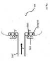
- Fig. 10 shows an exemplary section of a patient interface 105 of the ventilator 1.
- the light sources 41, 42, 43 are arranged, for example, in the area of the outflow openings 1053.
- covers 1051 are attached, for example, which have a similar or the same function as that in FIG Fig. 6-9 baffle surfaces 1021 described.
- the covers 1051 are connected to a part of the patient interface 105, for example.
- the breathing gas is supplied to the patient through the gas supply line 1052.
- the breathing gas exhaled by the patient leaves the patient interface with flow direction d through the outflow openings 1053 and hits the cover 1051 perpendicularly.
- the cover 1051 serves here on the one hand as a place to slow down the gas flow but also for at least temporary accumulation of pathogens or germs which are irradiated and weakened or inactivated by the light sources 41, 42, 43.
- the inactivated or weakened germs or pathogens are regularly removed by the gas flow, so that no permanent accumulation occurs.
Landscapes
- Health & Medical Sciences (AREA)
- Life Sciences & Earth Sciences (AREA)
- Veterinary Medicine (AREA)
- Public Health (AREA)
- General Health & Medical Sciences (AREA)
- Animal Behavior & Ethology (AREA)
- Engineering & Computer Science (AREA)
- Biomedical Technology (AREA)
- Hematology (AREA)
- Heart & Thoracic Surgery (AREA)
- Anesthesiology (AREA)
- Pulmonology (AREA)
- Emergency Medicine (AREA)
- Epidemiology (AREA)
- Chemical & Material Sciences (AREA)
- Chemical Kinetics & Catalysis (AREA)
- Biodiversity & Conservation Biology (AREA)
- Ecology (AREA)
- Environmental & Geological Engineering (AREA)
- Environmental Sciences (AREA)
- Apparatus For Disinfection Or Sterilisation (AREA)
- Disinfection, Sterilisation Or Deodorisation Of Air (AREA)
- Respiratory Apparatuses And Protective Means (AREA)
Applications Claiming Priority (1)
| Application Number | Priority Date | Filing Date | Title |
|---|---|---|---|
| DE102019110740 | 2019-04-25 |
Publications (2)
| Publication Number | Publication Date |
|---|---|
| EP3730158A1 true EP3730158A1 (fr) | 2020-10-28 |
| EP3730158B1 EP3730158B1 (fr) | 2022-01-12 |
Family
ID=70333759
Family Applications (1)
| Application Number | Title | Priority Date | Filing Date |
|---|---|---|---|
| EP20000156.8A Active EP3730158B1 (fr) | 2019-04-25 | 2020-04-16 | Appareil respiratoire |
Country Status (4)
| Country | Link |
|---|---|
| US (1) | US20200338297A1 (fr) |
| EP (1) | EP3730158B1 (fr) |
| CN (1) | CN111840718A (fr) |
| DE (1) | DE102020109727A1 (fr) |
Families Citing this family (3)
| Publication number | Priority date | Publication date | Assignee | Title |
|---|---|---|---|---|
| US11305032B2 (en) * | 2020-05-29 | 2022-04-19 | Stanley W. Ellis | Ultraviolet air irradiation system and ultraviolet air irradiation process |
| TR202106861A2 (tr) * | 2021-04-20 | 2021-06-21 | Afyon Kocatepe Ueniversitesi Rektoerluegue | Mekani̇k venti̇latör kaynakli aerosol vi̇rüs (kovi̇d-19) bulaşini engelleyen uv-c steri̇li̇zatörü |
| DE102024135185A1 (de) * | 2023-12-05 | 2025-06-05 | Löwenstein Medical Technology S.A. | Vorrichtung zur keimabwehr in einem beatmungssystem |
Citations (14)
| Publication number | Priority date | Publication date | Assignee | Title |
|---|---|---|---|---|
| US3126003A (en) * | 1964-03-24 | Filter | ||
| DE2347791A1 (de) * | 1973-09-22 | 1975-04-17 | Original Hanau Quarzlampen | Anordnung zur entkeimung von patientenatemluft |
| DE10107443A1 (de) | 2001-02-16 | 2002-08-29 | Heptec Gmbh | Verfahren zur Desinfektion von Frischluft, Luftdesinfektionsmodul sowie Blitzlampen |
| US20060177356A1 (en) * | 2005-02-08 | 2006-08-10 | Miller Gregory R | Positive pressure air purification and conditioning system |
| US20070163588A1 (en) * | 2005-11-08 | 2007-07-19 | Jack Hebrank | Respirators for Delivering Clean Air to an Individual User |
| US20080032119A1 (en) * | 2004-09-03 | 2008-02-07 | Karl-Andreas Feldhahn | Plastics For Medical Technical Devices |
| WO2011006206A1 (fr) * | 2009-07-17 | 2011-01-20 | Paftec Holdings Pty Ltd | Respirateur |
| WO2012052908A1 (fr) | 2010-10-18 | 2012-04-26 | Etview Ltd. | Tube trachéal |
| WO2014159874A1 (fr) | 2013-03-14 | 2014-10-02 | Teleflex Medical Incorporated | Système de thérapie par rayonnement ultraviolet antimicrobien basé sur une fibre optique |
| CN204233560U (zh) | 2014-10-11 | 2015-04-01 | 邱杨清 | 一种具有消毒冷凝排气管路的麻醉呼吸机 |
| WO2015092695A1 (fr) | 2013-12-18 | 2015-06-25 | Koninklijke Philips N.V. | Système de distribution de gaz et procédé de désinfection du trajet de flux de gaz dans un système de distribution de gaz |
| US20160271288A1 (en) | 2015-03-17 | 2016-09-22 | Matthew Phillip Davis | Ultraviolate light sterilization apparatus |
| WO2017023783A1 (fr) | 2015-07-31 | 2017-02-09 | Garrett Kurt A | Systèmes et procédés de stérilisation microbienne à l'aide d'une lumière polychromatique |
| US20180104374A1 (en) * | 2016-10-19 | 2018-04-19 | Samsung Electronics Co., Ltd. | Photocatalyst filter and air conditioner including the same |
Family Cites Families (9)
| Publication number | Priority date | Publication date | Assignee | Title |
|---|---|---|---|---|
| US5855203A (en) * | 1997-12-19 | 1999-01-05 | Matter; Jean-Paul | Respiratory circuit with in vivo sterilization |
| US8003058B2 (en) * | 2006-08-09 | 2011-08-23 | Airinspace B.V. | Air purification devices |
| DE102012010676A1 (de) * | 2012-05-31 | 2013-12-05 | Dräger Medical GmbH | Vorrichtung zur Verwendung in einem medizinischen Behandlungsraum |
| CN203291337U (zh) * | 2013-05-30 | 2013-11-20 | 史皆然 | 一种呼吸机管道工作状态下的连续净化除菌器 |
| DE102014014661B4 (de) * | 2014-10-08 | 2022-10-13 | Drägerwerk AG & Co. KGaA | Vorrichtung zur Entnahme und zum Transport eines Atemgasstromes |
| CN204134386U (zh) * | 2014-10-14 | 2015-02-04 | 浙江成致气动科技有限公司 | 一种空气过滤器 |
| US10960090B2 (en) * | 2015-03-18 | 2021-03-30 | Current Lighting Solutions, Llc | Light disinfection system and method |
| US10870015B2 (en) * | 2015-04-30 | 2020-12-22 | Light Line Medical, Inc. | Methods and apparatus to deliver therapeutic non-ultraviolet electromagnetic radiation for an endotracheal tube |
| CN205936897U (zh) * | 2016-05-26 | 2017-02-08 | 温州永清汽车过滤器有限公司 | 汽车空气过滤器 |
-
2020
- 2020-04-07 DE DE102020109727.1A patent/DE102020109727A1/de active Pending
- 2020-04-16 EP EP20000156.8A patent/EP3730158B1/fr active Active
- 2020-04-22 US US16/855,136 patent/US20200338297A1/en active Pending
- 2020-04-23 CN CN202010326514.1A patent/CN111840718A/zh active Pending
Patent Citations (14)
| Publication number | Priority date | Publication date | Assignee | Title |
|---|---|---|---|---|
| US3126003A (en) * | 1964-03-24 | Filter | ||
| DE2347791A1 (de) * | 1973-09-22 | 1975-04-17 | Original Hanau Quarzlampen | Anordnung zur entkeimung von patientenatemluft |
| DE10107443A1 (de) | 2001-02-16 | 2002-08-29 | Heptec Gmbh | Verfahren zur Desinfektion von Frischluft, Luftdesinfektionsmodul sowie Blitzlampen |
| US20080032119A1 (en) * | 2004-09-03 | 2008-02-07 | Karl-Andreas Feldhahn | Plastics For Medical Technical Devices |
| US20060177356A1 (en) * | 2005-02-08 | 2006-08-10 | Miller Gregory R | Positive pressure air purification and conditioning system |
| US20070163588A1 (en) * | 2005-11-08 | 2007-07-19 | Jack Hebrank | Respirators for Delivering Clean Air to an Individual User |
| WO2011006206A1 (fr) * | 2009-07-17 | 2011-01-20 | Paftec Holdings Pty Ltd | Respirateur |
| WO2012052908A1 (fr) | 2010-10-18 | 2012-04-26 | Etview Ltd. | Tube trachéal |
| WO2014159874A1 (fr) | 2013-03-14 | 2014-10-02 | Teleflex Medical Incorporated | Système de thérapie par rayonnement ultraviolet antimicrobien basé sur une fibre optique |
| WO2015092695A1 (fr) | 2013-12-18 | 2015-06-25 | Koninklijke Philips N.V. | Système de distribution de gaz et procédé de désinfection du trajet de flux de gaz dans un système de distribution de gaz |
| CN204233560U (zh) | 2014-10-11 | 2015-04-01 | 邱杨清 | 一种具有消毒冷凝排气管路的麻醉呼吸机 |
| US20160271288A1 (en) | 2015-03-17 | 2016-09-22 | Matthew Phillip Davis | Ultraviolate light sterilization apparatus |
| WO2017023783A1 (fr) | 2015-07-31 | 2017-02-09 | Garrett Kurt A | Systèmes et procédés de stérilisation microbienne à l'aide d'une lumière polychromatique |
| US20180104374A1 (en) * | 2016-10-19 | 2018-04-19 | Samsung Electronics Co., Ltd. | Photocatalyst filter and air conditioner including the same |
Also Published As
| Publication number | Publication date |
|---|---|
| US20200338297A1 (en) | 2020-10-29 |
| EP3730158B1 (fr) | 2022-01-12 |
| DE102020109727A1 (de) | 2020-10-29 |
| CN111840718A (zh) | 2020-10-30 |
Similar Documents
| Publication | Publication Date | Title |
|---|---|---|
| DE102017009637B4 (de) | Handtrockner mit UV-Desinfektionsvorrichtung | |
| EP3730158B1 (fr) | Appareil respiratoire | |
| EP0915713A1 (fr) | Procede et dispositif de filtrage ultra-pur et de desinfection de l'air a respirer | |
| DE102012008253A1 (de) | Trockner, insbesondere Handtrockner | |
| DE102020106235B3 (de) | Atemschutzmaske | |
| DE102018125596A1 (de) | Vorrichtung und Verfahren zur Entkeimung eines Gases oder Gasgemisches mit UVC-Strahlung | |
| DE102020120046A1 (de) | Vorrichtung zur Desinfektion von Luft | |
| DE102011001097A1 (de) | Türgarnitur mit einer Einrichtung zur Desinfizierung | |
| DE102021000458A1 (de) | Luftsterilisator | |
| DE102020119225B3 (de) | Vorrichtung zur Desinfektion von Luft in Innenräumen | |
| DE102011001094A1 (de) | Türgarnitur mit einer Einrichtung zur Desinfizierung | |
| DE202013000809U1 (de) | Ultraviolett-Luftdesinfektionsvorrichtung | |
| WO2002065972A2 (fr) | Procede de desinfection d'air frais, module de desinfection d'air, dispositif cpap, humidificateur d'air, appareil respiratoire, lampe-eclair, et lampe a decharge gazeuse | |
| DE202020002865U1 (de) | Vorrichtung zur Sedimentation und Oxydation von Feinstäuben und Aerosolen undorganischen Belastungen wie Viren in einem Gerät und der elektrostatischen sowieelektrochemischen oder photochemischen Aufbereitung der aus dem Gerät einemRaum zugeführten Luft für analoge Prozesse im Raum. | |
| DE102020003124A1 (de) | Virenschutz-Vorrichtung für eine Luftdurchströmungs- / Belüftungs-Vorrichtung oder Lüftungs-Anlage oder Klima-Anlage | |
| DE102020204403B4 (de) | Vorrichtung zur Desinfektion von Luft in/an Atemschutzmaske oder Beatmungsgerät | |
| DE202025102292U1 (de) | Mehrfach lineargitterbasierte GUV-LED-Fluid-Sterilisationsvorrichtung | |
| DE102019211247B4 (de) | Kaltlufttherapiegerät, verfahren zum applizieren eines abgekühlten luftstroms und verwendung einer luftentkeimungseinrichtung | |
| DE102012003548A1 (de) | Medizinisches Gerät zur Behandlung eines Patienten | |
| DE202020105930U1 (de) | Dunstabzug | |
| EP4378488B1 (fr) | Dispositif d'imagerie, dispositif de conduit d'air et procédé de fonctionnement d'un dispositif d'imagerie | |
| DE202020105280U1 (de) | Atemschutz-Baukastensystem | |
| DE202020004562U1 (de) | Luftreiniger mit Sterilisationsunterstützung | |
| DE102004021585A1 (de) | Vorrichtung zur Entkeimung | |
| DE102021105374A1 (de) | Luftaufbereitungsapparat |
Legal Events
| Date | Code | Title | Description |
|---|---|---|---|
| PUAI | Public reference made under article 153(3) epc to a published international application that has entered the european phase |
Free format text: ORIGINAL CODE: 0009012 |
|
| STAA | Information on the status of an ep patent application or granted ep patent |
Free format text: STATUS: THE APPLICATION HAS BEEN PUBLISHED |
|
| AK | Designated contracting states |
Kind code of ref document: A1 Designated state(s): AL AT BE BG CH CY CZ DE DK EE ES FI FR GB GR HR HU IE IS IT LI LT LU LV MC MK MT NL NO PL PT RO RS SE SI SK SM TR |
|
| AX | Request for extension of the european patent |
Extension state: BA ME |
|
| STAA | Information on the status of an ep patent application or granted ep patent |
Free format text: STATUS: REQUEST FOR EXAMINATION WAS MADE |
|
| 17P | Request for examination filed |
Effective date: 20210422 |
|
| RBV | Designated contracting states (corrected) |
Designated state(s): AL AT BE BG CH CY CZ DE DK EE ES FI FR GB GR HR HU IE IS IT LI LT LU LV MC MK MT NL NO PL PT RO RS SE SI SK SM TR |
|
| GRAP | Despatch of communication of intention to grant a patent |
Free format text: ORIGINAL CODE: EPIDOSNIGR1 |
|
| STAA | Information on the status of an ep patent application or granted ep patent |
Free format text: STATUS: GRANT OF PATENT IS INTENDED |
|
| RIC1 | Information provided on ipc code assigned before grant |
Ipc: A61L 2/08 20060101ALN20210827BHEP Ipc: A61M 39/02 20060101ALN20210827BHEP Ipc: A61M 16/00 20060101ALI20210827BHEP Ipc: A61M 16/10 20060101ALI20210827BHEP Ipc: A61M 39/16 20060101ALI20210827BHEP Ipc: A61L 9/20 20060101AFI20210827BHEP |
|
| RIC1 | Information provided on ipc code assigned before grant |
Ipc: A61L 2/08 20060101ALN20210908BHEP Ipc: A61M 39/02 20060101ALN20210908BHEP Ipc: A61M 16/00 20060101ALI20210908BHEP Ipc: A61M 16/10 20060101ALI20210908BHEP Ipc: A61M 39/16 20060101ALI20210908BHEP Ipc: A61L 9/20 20060101AFI20210908BHEP |
|
| INTG | Intention to grant announced |
Effective date: 20210921 |
|
| GRAS | Grant fee paid |
Free format text: ORIGINAL CODE: EPIDOSNIGR3 |
|
| GRAA | (expected) grant |
Free format text: ORIGINAL CODE: 0009210 |
|
| STAA | Information on the status of an ep patent application or granted ep patent |
Free format text: STATUS: THE PATENT HAS BEEN GRANTED |
|
| AK | Designated contracting states |
Kind code of ref document: B1 Designated state(s): AL AT BE BG CH CY CZ DE DK EE ES FI FR GB GR HR HU IE IS IT LI LT LU LV MC MK MT NL NO PL PT RO RS SE SI SK SM TR |
|
| REG | Reference to a national code |
Ref country code: GB Ref legal event code: FG4D Free format text: NOT ENGLISH |
|
| REG | Reference to a national code |
Ref country code: CH Ref legal event code: EP |
|
| REG | Reference to a national code |
Ref country code: DE Ref legal event code: R096 Ref document number: 502020000526 Country of ref document: DE |
|
| REG | Reference to a national code |
Ref country code: IE Ref legal event code: FG4D Free format text: LANGUAGE OF EP DOCUMENT: GERMAN |
|
| REG | Reference to a national code |
Ref country code: AT Ref legal event code: REF Ref document number: 1461959 Country of ref document: AT Kind code of ref document: T Effective date: 20220215 |
|
| REG | Reference to a national code |
Ref country code: LT Ref legal event code: MG9D |
|
| PG25 | Lapsed in a contracting state [announced via postgrant information from national office to epo] |
Ref country code: NL Free format text: LAPSE BECAUSE OF FAILURE TO SUBMIT A TRANSLATION OF THE DESCRIPTION OR TO PAY THE FEE WITHIN THE PRESCRIBED TIME-LIMIT Effective date: 20220112 |
|
| PG25 | Lapsed in a contracting state [announced via postgrant information from national office to epo] |
Ref country code: SE Free format text: LAPSE BECAUSE OF FAILURE TO SUBMIT A TRANSLATION OF THE DESCRIPTION OR TO PAY THE FEE WITHIN THE PRESCRIBED TIME-LIMIT Effective date: 20220112 Ref country code: RS Free format text: LAPSE BECAUSE OF FAILURE TO SUBMIT A TRANSLATION OF THE DESCRIPTION OR TO PAY THE FEE WITHIN THE PRESCRIBED TIME-LIMIT Effective date: 20220112 Ref country code: PT Free format text: LAPSE BECAUSE OF FAILURE TO SUBMIT A TRANSLATION OF THE DESCRIPTION OR TO PAY THE FEE WITHIN THE PRESCRIBED TIME-LIMIT Effective date: 20220512 Ref country code: NO Free format text: LAPSE BECAUSE OF FAILURE TO SUBMIT A TRANSLATION OF THE DESCRIPTION OR TO PAY THE FEE WITHIN THE PRESCRIBED TIME-LIMIT Effective date: 20220412 Ref country code: LT Free format text: LAPSE BECAUSE OF FAILURE TO SUBMIT A TRANSLATION OF THE DESCRIPTION OR TO PAY THE FEE WITHIN THE PRESCRIBED TIME-LIMIT Effective date: 20220112 Ref country code: HR Free format text: LAPSE BECAUSE OF FAILURE TO SUBMIT A TRANSLATION OF THE DESCRIPTION OR TO PAY THE FEE WITHIN THE PRESCRIBED TIME-LIMIT Effective date: 20220112 Ref country code: ES Free format text: LAPSE BECAUSE OF FAILURE TO SUBMIT A TRANSLATION OF THE DESCRIPTION OR TO PAY THE FEE WITHIN THE PRESCRIBED TIME-LIMIT Effective date: 20220112 Ref country code: BG Free format text: LAPSE BECAUSE OF FAILURE TO SUBMIT A TRANSLATION OF THE DESCRIPTION OR TO PAY THE FEE WITHIN THE PRESCRIBED TIME-LIMIT Effective date: 20220412 |
|
| PG25 | Lapsed in a contracting state [announced via postgrant information from national office to epo] |
Ref country code: PL Free format text: LAPSE BECAUSE OF FAILURE TO SUBMIT A TRANSLATION OF THE DESCRIPTION OR TO PAY THE FEE WITHIN THE PRESCRIBED TIME-LIMIT Effective date: 20220112 Ref country code: LV Free format text: LAPSE BECAUSE OF FAILURE TO SUBMIT A TRANSLATION OF THE DESCRIPTION OR TO PAY THE FEE WITHIN THE PRESCRIBED TIME-LIMIT Effective date: 20220112 Ref country code: GR Free format text: LAPSE BECAUSE OF FAILURE TO SUBMIT A TRANSLATION OF THE DESCRIPTION OR TO PAY THE FEE WITHIN THE PRESCRIBED TIME-LIMIT Effective date: 20220413 Ref country code: FI Free format text: LAPSE BECAUSE OF FAILURE TO SUBMIT A TRANSLATION OF THE DESCRIPTION OR TO PAY THE FEE WITHIN THE PRESCRIBED TIME-LIMIT Effective date: 20220112 |
|
| PG25 | Lapsed in a contracting state [announced via postgrant information from national office to epo] |
Ref country code: IS Free format text: LAPSE BECAUSE OF FAILURE TO SUBMIT A TRANSLATION OF THE DESCRIPTION OR TO PAY THE FEE WITHIN THE PRESCRIBED TIME-LIMIT Effective date: 20220512 |
|
| REG | Reference to a national code |
Ref country code: DE Ref legal event code: R097 Ref document number: 502020000526 Country of ref document: DE |
|
| PG25 | Lapsed in a contracting state [announced via postgrant information from national office to epo] |
Ref country code: SM Free format text: LAPSE BECAUSE OF FAILURE TO SUBMIT A TRANSLATION OF THE DESCRIPTION OR TO PAY THE FEE WITHIN THE PRESCRIBED TIME-LIMIT Effective date: 20220112 Ref country code: SK Free format text: LAPSE BECAUSE OF FAILURE TO SUBMIT A TRANSLATION OF THE DESCRIPTION OR TO PAY THE FEE WITHIN THE PRESCRIBED TIME-LIMIT Effective date: 20220112 Ref country code: RO Free format text: LAPSE BECAUSE OF FAILURE TO SUBMIT A TRANSLATION OF THE DESCRIPTION OR TO PAY THE FEE WITHIN THE PRESCRIBED TIME-LIMIT Effective date: 20220112 Ref country code: EE Free format text: LAPSE BECAUSE OF FAILURE TO SUBMIT A TRANSLATION OF THE DESCRIPTION OR TO PAY THE FEE WITHIN THE PRESCRIBED TIME-LIMIT Effective date: 20220112 Ref country code: DK Free format text: LAPSE BECAUSE OF FAILURE TO SUBMIT A TRANSLATION OF THE DESCRIPTION OR TO PAY THE FEE WITHIN THE PRESCRIBED TIME-LIMIT Effective date: 20220112 Ref country code: CZ Free format text: LAPSE BECAUSE OF FAILURE TO SUBMIT A TRANSLATION OF THE DESCRIPTION OR TO PAY THE FEE WITHIN THE PRESCRIBED TIME-LIMIT Effective date: 20220112 |
|
| PLBE | No opposition filed within time limit |
Free format text: ORIGINAL CODE: 0009261 |
|
| STAA | Information on the status of an ep patent application or granted ep patent |
Free format text: STATUS: NO OPPOSITION FILED WITHIN TIME LIMIT |
|
| PG25 | Lapsed in a contracting state [announced via postgrant information from national office to epo] |
Ref country code: AL Free format text: LAPSE BECAUSE OF FAILURE TO SUBMIT A TRANSLATION OF THE DESCRIPTION OR TO PAY THE FEE WITHIN THE PRESCRIBED TIME-LIMIT Effective date: 20220112 |
|
| 26N | No opposition filed |
Effective date: 20221013 |
|
| REG | Reference to a national code |
Ref country code: BE Ref legal event code: MM Effective date: 20220430 |
|
| PG25 | Lapsed in a contracting state [announced via postgrant information from national office to epo] |
Ref country code: MC Free format text: LAPSE BECAUSE OF FAILURE TO SUBMIT A TRANSLATION OF THE DESCRIPTION OR TO PAY THE FEE WITHIN THE PRESCRIBED TIME-LIMIT Effective date: 20220112 Ref country code: LU Free format text: LAPSE BECAUSE OF NON-PAYMENT OF DUE FEES Effective date: 20220416 |
|
| PG25 | Lapsed in a contracting state [announced via postgrant information from national office to epo] |
Ref country code: SI Free format text: LAPSE BECAUSE OF FAILURE TO SUBMIT A TRANSLATION OF THE DESCRIPTION OR TO PAY THE FEE WITHIN THE PRESCRIBED TIME-LIMIT Effective date: 20220112 Ref country code: BE Free format text: LAPSE BECAUSE OF NON-PAYMENT OF DUE FEES Effective date: 20220430 |
|
| PG25 | Lapsed in a contracting state [announced via postgrant information from national office to epo] |
Ref country code: IE Free format text: LAPSE BECAUSE OF NON-PAYMENT OF DUE FEES Effective date: 20220416 |
|
| P01 | Opt-out of the competence of the unified patent court (upc) registered |
Effective date: 20230523 |
|
| PG25 | Lapsed in a contracting state [announced via postgrant information from national office to epo] |
Ref country code: IT Free format text: LAPSE BECAUSE OF FAILURE TO SUBMIT A TRANSLATION OF THE DESCRIPTION OR TO PAY THE FEE WITHIN THE PRESCRIBED TIME-LIMIT Effective date: 20220112 |
|
| PG25 | Lapsed in a contracting state [announced via postgrant information from national office to epo] |
Ref country code: MK Free format text: LAPSE BECAUSE OF FAILURE TO SUBMIT A TRANSLATION OF THE DESCRIPTION OR TO PAY THE FEE WITHIN THE PRESCRIBED TIME-LIMIT Effective date: 20220112 Ref country code: CY Free format text: LAPSE BECAUSE OF FAILURE TO SUBMIT A TRANSLATION OF THE DESCRIPTION OR TO PAY THE FEE WITHIN THE PRESCRIBED TIME-LIMIT Effective date: 20220112 |
|
| PG25 | Lapsed in a contracting state [announced via postgrant information from national office to epo] |
Ref country code: HU Free format text: LAPSE BECAUSE OF FAILURE TO SUBMIT A TRANSLATION OF THE DESCRIPTION OR TO PAY THE FEE WITHIN THE PRESCRIBED TIME-LIMIT; INVALID AB INITIO Effective date: 20200416 |
|
| PG25 | Lapsed in a contracting state [announced via postgrant information from national office to epo] |
Ref country code: TR Free format text: LAPSE BECAUSE OF FAILURE TO SUBMIT A TRANSLATION OF THE DESCRIPTION OR TO PAY THE FEE WITHIN THE PRESCRIBED TIME-LIMIT Effective date: 20220112 |
|
| PG25 | Lapsed in a contracting state [announced via postgrant information from national office to epo] |
Ref country code: MT Free format text: LAPSE BECAUSE OF FAILURE TO SUBMIT A TRANSLATION OF THE DESCRIPTION OR TO PAY THE FEE WITHIN THE PRESCRIBED TIME-LIMIT Effective date: 20220112 |
|
| PGFP | Annual fee paid to national office [announced via postgrant information from national office to epo] |
Ref country code: DE Payment date: 20250417 Year of fee payment: 6 |
|
| PGFP | Annual fee paid to national office [announced via postgrant information from national office to epo] |
Ref country code: FR Payment date: 20250422 Year of fee payment: 6 |
|
| PGFP | Annual fee paid to national office [announced via postgrant information from national office to epo] |
Ref country code: CH Payment date: 20250501 Year of fee payment: 6 |
|
| PGFP | Annual fee paid to national office [announced via postgrant information from national office to epo] |
Ref country code: AT Payment date: 20250721 Year of fee payment: 5 |
|
| PGFP | Annual fee paid to national office [announced via postgrant information from national office to epo] |
Ref country code: GB Payment date: 20260324 Year of fee payment: 7 |
|
| REG | Reference to a national code |
Ref country code: CH Ref legal event code: U11 Free format text: ST27 STATUS EVENT CODE: U-0-0-U10-U11 (AS PROVIDED BY THE NATIONAL OFFICE) Effective date: 20260501 |