EP3730169B1 - Dispositif d'administration de medicaments avec detection de position du piston - Google Patents
Dispositif d'administration de medicaments avec detection de position du piston Download PDFInfo
- Publication number
- EP3730169B1 EP3730169B1 EP20174878.7A EP20174878A EP3730169B1 EP 3730169 B1 EP3730169 B1 EP 3730169B1 EP 20174878 A EP20174878 A EP 20174878A EP 3730169 B1 EP3730169 B1 EP 3730169B1
- Authority
- EP
- European Patent Office
- Prior art keywords
- drug
- plunger
- drug container
- container
- light
- Prior art date
- Legal status (The legal status is an assumption and is not a legal conclusion. Google has not performed a legal analysis and makes no representation as to the accuracy of the status listed.)
- Active
Links
Images


Classifications
-
- A—HUMAN NECESSITIES
- A61—MEDICAL OR VETERINARY SCIENCE; HYGIENE
- A61M—DEVICES FOR INTRODUCING MEDIA INTO, OR ONTO, THE BODY; DEVICES FOR TRANSDUCING BODY MEDIA OR FOR TAKING MEDIA FROM THE BODY; DEVICES FOR PRODUCING OR ENDING SLEEP OR STUPOR
- A61M5/00—Devices for bringing media into the body in a subcutaneous, intra-vascular or intramuscular way; Accessories therefor, e.g. filling or cleaning devices, arm-rests
- A61M5/14—Infusion devices, e.g. infusing by gravity; Blood infusion; Accessories therefor
- A61M5/168—Means for controlling media flow to the body or for metering media to the body, e.g. drip meters, counters ; Monitoring media flow to the body
- A61M5/16886—Means for controlling media flow to the body or for metering media to the body, e.g. drip meters, counters ; Monitoring media flow to the body for measuring fluid flow rate, i.e. flowmeters
-
- A—HUMAN NECESSITIES
- A61—MEDICAL OR VETERINARY SCIENCE; HYGIENE
- A61M—DEVICES FOR INTRODUCING MEDIA INTO, OR ONTO, THE BODY; DEVICES FOR TRANSDUCING BODY MEDIA OR FOR TAKING MEDIA FROM THE BODY; DEVICES FOR PRODUCING OR ENDING SLEEP OR STUPOR
- A61M5/00—Devices for bringing media into the body in a subcutaneous, intra-vascular or intramuscular way; Accessories therefor, e.g. filling or cleaning devices, arm-rests
- A61M5/178—Syringes
- A61M5/31—Details
- A61M5/315—Pistons; Piston-rods; Guiding, blocking or restricting the movement of the rod or piston; Appliances on the rod for facilitating dosing ; Dosing mechanisms
- A61M5/31565—Administration mechanisms, i.e. constructional features, modes of administering a dose
- A61M5/31566—Means improving security or handling thereof
- A61M5/31568—Means keeping track of the total dose administered, e.g. since the cartridge was inserted
-
- A—HUMAN NECESSITIES
- A61—MEDICAL OR VETERINARY SCIENCE; HYGIENE
- A61M—DEVICES FOR INTRODUCING MEDIA INTO, OR ONTO, THE BODY; DEVICES FOR TRANSDUCING BODY MEDIA OR FOR TAKING MEDIA FROM THE BODY; DEVICES FOR PRODUCING OR ENDING SLEEP OR STUPOR
- A61M5/00—Devices for bringing media into the body in a subcutaneous, intra-vascular or intramuscular way; Accessories therefor, e.g. filling or cleaning devices, arm-rests
- A61M5/14—Infusion devices, e.g. infusing by gravity; Blood infusion; Accessories therefor
- A61M5/142—Pressure infusion, e.g. using pumps
- A61M5/14244—Pressure infusion, e.g. using pumps adapted to be carried by the patient, e.g. portable on the body
- A61M5/14248—Pressure infusion, e.g. using pumps adapted to be carried by the patient, e.g. portable on the body of the skin patch type
-
- A—HUMAN NECESSITIES
- A61—MEDICAL OR VETERINARY SCIENCE; HYGIENE
- A61M—DEVICES FOR INTRODUCING MEDIA INTO, OR ONTO, THE BODY; DEVICES FOR TRANSDUCING BODY MEDIA OR FOR TAKING MEDIA FROM THE BODY; DEVICES FOR PRODUCING OR ENDING SLEEP OR STUPOR
- A61M5/00—Devices for bringing media into the body in a subcutaneous, intra-vascular or intramuscular way; Accessories therefor, e.g. filling or cleaning devices, arm-rests
- A61M5/14—Infusion devices, e.g. infusing by gravity; Blood infusion; Accessories therefor
- A61M5/142—Pressure infusion, e.g. using pumps
- A61M5/145—Pressure infusion, e.g. using pumps using pressurised reservoirs, e.g. pressurised by means of pistons
- A61M5/1452—Pressure infusion, e.g. using pumps using pressurised reservoirs, e.g. pressurised by means of pistons pressurised by means of pistons
- A61M5/1454—Pressure infusion, e.g. using pumps using pressurised reservoirs, e.g. pressurised by means of pistons pressurised by means of pistons spring-actuated, e.g. by a clockwork
-
- A—HUMAN NECESSITIES
- A61—MEDICAL OR VETERINARY SCIENCE; HYGIENE
- A61M—DEVICES FOR INTRODUCING MEDIA INTO, OR ONTO, THE BODY; DEVICES FOR TRANSDUCING BODY MEDIA OR FOR TAKING MEDIA FROM THE BODY; DEVICES FOR PRODUCING OR ENDING SLEEP OR STUPOR
- A61M5/00—Devices for bringing media into the body in a subcutaneous, intra-vascular or intramuscular way; Accessories therefor, e.g. filling or cleaning devices, arm-rests
- A61M5/14—Infusion devices, e.g. infusing by gravity; Blood infusion; Accessories therefor
- A61M5/168—Means for controlling media flow to the body or for metering media to the body, e.g. drip meters, counters ; Monitoring media flow to the body
- A61M5/16831—Monitoring, detecting, signalling or eliminating infusion flow anomalies
- A61M5/1684—Monitoring, detecting, signalling or eliminating infusion flow anomalies by detecting the amount of infusate remaining, e.g. signalling end of infusion
-
- A—HUMAN NECESSITIES
- A61—MEDICAL OR VETERINARY SCIENCE; HYGIENE
- A61M—DEVICES FOR INTRODUCING MEDIA INTO, OR ONTO, THE BODY; DEVICES FOR TRANSDUCING BODY MEDIA OR FOR TAKING MEDIA FROM THE BODY; DEVICES FOR PRODUCING OR ENDING SLEEP OR STUPOR
- A61M5/00—Devices for bringing media into the body in a subcutaneous, intra-vascular or intramuscular way; Accessories therefor, e.g. filling or cleaning devices, arm-rests
- A61M5/178—Syringes
- A61M5/20—Automatic syringes, e.g. with automatically actuated piston rod, with automatic needle injection, filling automatically
- A61M5/2033—Spring-loaded one-shot injectors with or without automatic needle insertion
-
- G—PHYSICS
- G01—MEASURING; TESTING
- G01F—MEASURING VOLUME, VOLUME FLOW, MASS FLOW OR LIQUID LEVEL; METERING BY VOLUME
- G01F13/00—Apparatus for measuring by volume and delivering fluids or fluent solid materials, not provided for in the preceding groups
-
- A—HUMAN NECESSITIES
- A61—MEDICAL OR VETERINARY SCIENCE; HYGIENE
- A61M—DEVICES FOR INTRODUCING MEDIA INTO, OR ONTO, THE BODY; DEVICES FOR TRANSDUCING BODY MEDIA OR FOR TAKING MEDIA FROM THE BODY; DEVICES FOR PRODUCING OR ENDING SLEEP OR STUPOR
- A61M5/00—Devices for bringing media into the body in a subcutaneous, intra-vascular or intramuscular way; Accessories therefor, e.g. filling or cleaning devices, arm-rests
- A61M5/14—Infusion devices, e.g. infusing by gravity; Blood infusion; Accessories therefor
- A61M5/142—Pressure infusion, e.g. using pumps
- A61M5/14244—Pressure infusion, e.g. using pumps adapted to be carried by the patient, e.g. portable on the body
- A61M5/14248—Pressure infusion, e.g. using pumps adapted to be carried by the patient, e.g. portable on the body of the skin patch type
- A61M2005/14252—Pressure infusion, e.g. using pumps adapted to be carried by the patient, e.g. portable on the body of the skin patch type with needle insertion means
-
- A—HUMAN NECESSITIES
- A61—MEDICAL OR VETERINARY SCIENCE; HYGIENE
- A61M—DEVICES FOR INTRODUCING MEDIA INTO, OR ONTO, THE BODY; DEVICES FOR TRANSDUCING BODY MEDIA OR FOR TAKING MEDIA FROM THE BODY; DEVICES FOR PRODUCING OR ENDING SLEEP OR STUPOR
- A61M5/00—Devices for bringing media into the body in a subcutaneous, intra-vascular or intramuscular way; Accessories therefor, e.g. filling or cleaning devices, arm-rests
- A61M5/14—Infusion devices, e.g. infusing by gravity; Blood infusion; Accessories therefor
- A61M5/142—Pressure infusion, e.g. using pumps
- A61M5/145—Pressure infusion, e.g. using pumps using pressurised reservoirs, e.g. pressurised by means of pistons
- A61M5/1452—Pressure infusion, e.g. using pumps using pressurised reservoirs, e.g. pressurised by means of pistons pressurised by means of pistons
- A61M2005/14533—Pressure infusion, e.g. using pumps using pressurised reservoirs, e.g. pressurised by means of pistons pressurised by means of pistons cam actuated
-
- A—HUMAN NECESSITIES
- A61—MEDICAL OR VETERINARY SCIENCE; HYGIENE
- A61M—DEVICES FOR INTRODUCING MEDIA INTO, OR ONTO, THE BODY; DEVICES FOR TRANSDUCING BODY MEDIA OR FOR TAKING MEDIA FROM THE BODY; DEVICES FOR PRODUCING OR ENDING SLEEP OR STUPOR
- A61M5/00—Devices for bringing media into the body in a subcutaneous, intra-vascular or intramuscular way; Accessories therefor, e.g. filling or cleaning devices, arm-rests
- A61M5/178—Syringes
- A61M5/20—Automatic syringes, e.g. with automatically actuated piston rod, with automatic needle injection, filling automatically
- A61M2005/2073—Automatic syringes, e.g. with automatically actuated piston rod, with automatic needle injection, filling automatically preventing premature release, e.g. by making use of a safety lock
-
- A—HUMAN NECESSITIES
- A61—MEDICAL OR VETERINARY SCIENCE; HYGIENE
- A61M—DEVICES FOR INTRODUCING MEDIA INTO, OR ONTO, THE BODY; DEVICES FOR TRANSDUCING BODY MEDIA OR FOR TAKING MEDIA FROM THE BODY; DEVICES FOR PRODUCING OR ENDING SLEEP OR STUPOR
- A61M5/00—Devices for bringing media into the body in a subcutaneous, intra-vascular or intramuscular way; Accessories therefor, e.g. filling or cleaning devices, arm-rests
- A61M5/178—Syringes
- A61M5/31—Details
- A61M5/315—Pistons; Piston-rods; Guiding, blocking or restricting the movement of the rod or piston; Appliances on the rod for facilitating dosing ; Dosing mechanisms
- A61M5/31511—Piston or piston-rod constructions, e.g. connection of piston with piston-rod
- A61M2005/31518—Piston or piston-rod constructions, e.g. connection of piston with piston-rod designed to reduce the overall size of an injection device, e.g. using flexible or pivotally connected chain-like rod members
-
- A—HUMAN NECESSITIES
- A61—MEDICAL OR VETERINARY SCIENCE; HYGIENE
- A61M—DEVICES FOR INTRODUCING MEDIA INTO, OR ONTO, THE BODY; DEVICES FOR TRANSDUCING BODY MEDIA OR FOR TAKING MEDIA FROM THE BODY; DEVICES FOR PRODUCING OR ENDING SLEEP OR STUPOR
- A61M2202/00—Special media to be introduced, removed or treated
- A61M2202/04—Liquids
- A61M2202/0468—Liquids non-physiological
-
- A—HUMAN NECESSITIES
- A61—MEDICAL OR VETERINARY SCIENCE; HYGIENE
- A61M—DEVICES FOR INTRODUCING MEDIA INTO, OR ONTO, THE BODY; DEVICES FOR TRANSDUCING BODY MEDIA OR FOR TAKING MEDIA FROM THE BODY; DEVICES FOR PRODUCING OR ENDING SLEEP OR STUPOR
- A61M2205/00—General characteristics of the apparatus
- A61M2205/33—Controlling, regulating or measuring
- A61M2205/3306—Optical measuring means
-
- A—HUMAN NECESSITIES
- A61—MEDICAL OR VETERINARY SCIENCE; HYGIENE
- A61M—DEVICES FOR INTRODUCING MEDIA INTO, OR ONTO, THE BODY; DEVICES FOR TRANSDUCING BODY MEDIA OR FOR TAKING MEDIA FROM THE BODY; DEVICES FOR PRODUCING OR ENDING SLEEP OR STUPOR
- A61M2205/00—General characteristics of the apparatus
- A61M2205/33—Controlling, regulating or measuring
- A61M2205/3317—Electromagnetic, inductive or dielectric measuring means
-
- A—HUMAN NECESSITIES
- A61—MEDICAL OR VETERINARY SCIENCE; HYGIENE
- A61M—DEVICES FOR INTRODUCING MEDIA INTO, OR ONTO, THE BODY; DEVICES FOR TRANSDUCING BODY MEDIA OR FOR TAKING MEDIA FROM THE BODY; DEVICES FOR PRODUCING OR ENDING SLEEP OR STUPOR
- A61M2205/00—General characteristics of the apparatus
- A61M2205/33—Controlling, regulating or measuring
- A61M2205/3379—Masses, volumes, levels of fluids in reservoirs, flow rates
- A61M2205/3389—Continuous level detection
-
- A—HUMAN NECESSITIES
- A61—MEDICAL OR VETERINARY SCIENCE; HYGIENE
- A61M—DEVICES FOR INTRODUCING MEDIA INTO, OR ONTO, THE BODY; DEVICES FOR TRANSDUCING BODY MEDIA OR FOR TAKING MEDIA FROM THE BODY; DEVICES FOR PRODUCING OR ENDING SLEEP OR STUPOR
- A61M2205/00—General characteristics of the apparatus
- A61M2205/58—Means for facilitating use, e.g. by people with impaired vision
- A61M2205/581—Means for facilitating use, e.g. by people with impaired vision by audible feedback
-
- A—HUMAN NECESSITIES
- A61—MEDICAL OR VETERINARY SCIENCE; HYGIENE
- A61M—DEVICES FOR INTRODUCING MEDIA INTO, OR ONTO, THE BODY; DEVICES FOR TRANSDUCING BODY MEDIA OR FOR TAKING MEDIA FROM THE BODY; DEVICES FOR PRODUCING OR ENDING SLEEP OR STUPOR
- A61M2205/00—General characteristics of the apparatus
- A61M2205/58—Means for facilitating use, e.g. by people with impaired vision
- A61M2205/582—Means for facilitating use, e.g. by people with impaired vision by tactile feedback
-
- A—HUMAN NECESSITIES
- A61—MEDICAL OR VETERINARY SCIENCE; HYGIENE
- A61M—DEVICES FOR INTRODUCING MEDIA INTO, OR ONTO, THE BODY; DEVICES FOR TRANSDUCING BODY MEDIA OR FOR TAKING MEDIA FROM THE BODY; DEVICES FOR PRODUCING OR ENDING SLEEP OR STUPOR
- A61M2205/00—General characteristics of the apparatus
- A61M2205/58—Means for facilitating use, e.g. by people with impaired vision
- A61M2205/583—Means for facilitating use, e.g. by people with impaired vision by visual feedback
- A61M2205/584—Means for facilitating use, e.g. by people with impaired vision by visual feedback having a color code
-
- A—HUMAN NECESSITIES
- A61—MEDICAL OR VETERINARY SCIENCE; HYGIENE
- A61M—DEVICES FOR INTRODUCING MEDIA INTO, OR ONTO, THE BODY; DEVICES FOR TRANSDUCING BODY MEDIA OR FOR TAKING MEDIA FROM THE BODY; DEVICES FOR PRODUCING OR ENDING SLEEP OR STUPOR
- A61M5/00—Devices for bringing media into the body in a subcutaneous, intra-vascular or intramuscular way; Accessories therefor, e.g. filling or cleaning devices, arm-rests
- A61M5/14—Infusion devices, e.g. infusing by gravity; Blood infusion; Accessories therefor
- A61M5/168—Means for controlling media flow to the body or for metering media to the body, e.g. drip meters, counters ; Monitoring media flow to the body
- A61M5/16831—Monitoring, detecting, signalling or eliminating infusion flow anomalies
- A61M5/1684—Monitoring, detecting, signalling or eliminating infusion flow anomalies by detecting the amount of infusate remaining, e.g. signalling end of infusion
- A61M5/1685—Monitoring, detecting, signalling or eliminating infusion flow anomalies by detecting the amount of infusate remaining, e.g. signalling end of infusion by detection of position of a floating member
-
- A—HUMAN NECESSITIES
- A61—MEDICAL OR VETERINARY SCIENCE; HYGIENE
- A61M—DEVICES FOR INTRODUCING MEDIA INTO, OR ONTO, THE BODY; DEVICES FOR TRANSDUCING BODY MEDIA OR FOR TAKING MEDIA FROM THE BODY; DEVICES FOR PRODUCING OR ENDING SLEEP OR STUPOR
- A61M5/00—Devices for bringing media into the body in a subcutaneous, intra-vascular or intramuscular way; Accessories therefor, e.g. filling or cleaning devices, arm-rests
- A61M5/178—Syringes
- A61M5/31—Details
- A61M5/3129—Syringe barrels
-
- A—HUMAN NECESSITIES
- A61—MEDICAL OR VETERINARY SCIENCE; HYGIENE
- A61M—DEVICES FOR INTRODUCING MEDIA INTO, OR ONTO, THE BODY; DEVICES FOR TRANSDUCING BODY MEDIA OR FOR TAKING MEDIA FROM THE BODY; DEVICES FOR PRODUCING OR ENDING SLEEP OR STUPOR
- A61M5/00—Devices for bringing media into the body in a subcutaneous, intra-vascular or intramuscular way; Accessories therefor, e.g. filling or cleaning devices, arm-rests
- A61M5/178—Syringes
- A61M5/31—Details
- A61M5/315—Pistons; Piston-rods; Guiding, blocking or restricting the movement of the rod or piston; Appliances on the rod for facilitating dosing ; Dosing mechanisms
- A61M5/31533—Dosing mechanisms, i.e. setting a dose
- A61M5/31545—Setting modes for dosing
- A61M5/31548—Mechanically operated dose setting member
- A61M5/3155—Mechanically operated dose setting member by rotational movement of dose setting member, e.g. during setting or filling of a syringe
-
- G—PHYSICS
- G01—MEASURING; TESTING
- G01F—MEASURING VOLUME, VOLUME FLOW, MASS FLOW OR LIQUID LEVEL; METERING BY VOLUME
- G01F11/00—Apparatus requiring external operation adapted at each repeated and identical operation to measure and separate a predetermined volume of fluid or fluent solid material from a supply or container, without regard to weight, and to deliver it
- G01F11/02—Apparatus requiring external operation adapted at each repeated and identical operation to measure and separate a predetermined volume of fluid or fluent solid material from a supply or container, without regard to weight, and to deliver it with measuring chambers which expand or contract during measurement
- G01F11/021—Apparatus requiring external operation adapted at each repeated and identical operation to measure and separate a predetermined volume of fluid or fluent solid material from a supply or container, without regard to weight, and to deliver it with measuring chambers which expand or contract during measurement of the piston type
- G01F11/029—Apparatus requiring external operation adapted at each repeated and identical operation to measure and separate a predetermined volume of fluid or fluent solid material from a supply or container, without regard to weight, and to deliver it with measuring chambers which expand or contract during measurement of the piston type provided with electric controlling means
Definitions
- Embodiments generally relate to medication delivery. More particularly, embodiments relate to wearable drug delivery devices.
- US2009/0278875A1 discloses a jetting device for jetting droplets of viscous medium onto a substrate, said jetting device comprising an ejector element for performing the jetting process and a jetting outlet through which said droplets are jetted.
- the document is related to a method, a measuring device, a jetting device, and a viscous medium container for use in such a jetting device for measuring or monitoring a level or volume of viscous medium during a jetting process and/or measuring electrical properties of the viscous medium to determine characteristics of the medium.
- US6539286B1 discloses a fluid level sensor used in a container in a system for dispensing adhesive used in the formation of electronic devices.
- the sensor includes a pair of electrical conductors positioned inside the container. A voltage is applied across the conductors to cause a current flow through the fluid in the container. The magnitude of the current flow represents the amount of fluid remaining in the container. If an empty container is detected, the system is shut off.
- US4371790A relates to an apparatus for measuring the level, volume or rate of flow of an electrically conductive fluid, such as water.
- the apparatus includes a reference conductor connected to a reference potential and a plurality of additional, vertically spaced conductors affixed to an insulating surface.
- the reference conductor is normally placed at the lowest point of the liquid container whereas the other conductors are positioned within the liquid container at various points above the reference conductor.
- the liquid effects an electrical conduction path between the conductors below the liquid level and the reference conductor and thus with the reference potential.
- the conductors are connected through a logic circuit to a plurality of display elements, which are selectively actuated to provide an indication of the level of the liquid corresponding to the uppermost conductor covered by the liquid and thereby connected to the reference potential.
- US3947692A relates to a digital transducer comprising a container having two disparate materials therein defining an interface, the interface being movable through the container responsive to a force, or forces, applied to one, or both, of the materials.
- a plurality of sensors are spaced along the container for sensing the interface, each of which is responsive to the presence of one of the materials.
- Means are included for suppressing the outputs of all of the sensing means responsive to the one material except that one sensing means which is responsive to the one material and nearest the interface.
- the invention comprises a wearable drug delivery device as defined in claim 1. Additional features of preferred embodiments are defined in the dependent claims. Particular reference regarding the invention is made to FIG. 11 and 12 , and the respective paragraphs of the following detailed description.
- This disclosure presents various systems, components, and methods related to a wearable drug delivery device and/or monitoring systems for determining a fill status of a drug container of a wearable drug delivery device.
- Each of the systems, components, and methods disclosed herein provides one or more advantages over conventional systems, components, and methods.
- Various embodiments include systems and methods for monitoring an operational state and/or a fill status of a drug container of a drug delivery device.
- the drug container can hold a liquid drug.
- a plunger can be positioned within the drug container.
- a drive system can advance the plunger to expel the liquid drug from the container.
- a monitoring system can detect a movement and/or a position of the plunger and/or any component coupled to the plunger. The detection can enable determination of an amount of liquid drug that has been expelled and/or an amount of liquid drug remaining in the drug container. Dosing rates, flow rates, and dosage completion can also be determined. Other embodiments are disclosed and described.
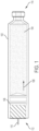
- FIG. 1 illustrates an exemplary drug container 102.
- the drug container 102 can hold or store a liquid drug or other therapeutic agent 104.
- the drug container 102 can be used within a drug delivery device such as, for Embodiment, a wearable drug delivery device.
- a plunger 106 can be used to expel the liquid drug 104 from the drug container 102 for delivery to a patient.
- a drive system or mechanism (not shown in FIG. 1 for simplicity) can provide a force on the plunger 106 to drive or advance the plunger 106 in a direction 108 to expel the liquid drug 104 from the drug container 102 (e.g., to advance the plunger 106 from a first position to a second position further into the drug container 102 to expel the liquid drug 104).
- a needle conduit 110 can provide the expelled liquid drug 104 to a patient. As shown in FIG. 1 , the needle conduit 110 can be coupled to the plunger 106 such that the expelled liquid drug 104 exits from a first end 112 of the drug container 102. Alternatively, the needle conduit 110 can be coupled to a second end 114 of the drug container 102 such that the expelled liquid drug 104 exits from the second end 114 of the drug container 102. The liquid drug 104 can be provided to the patient over one or more doses based on control of the drive mechanism.
- the drug container 102 can be made of a variety of materials including, for Embodiment, glass or plastic.
- the drug container 102 is not limited to the shape and size shown in FIG. 1 . Instead, the drug container 102 can be of any size or shape.
- the drug container 102 can be a prefilled or a fillable container.
- the drug container 102 can be an International Organization for Standardization (ISO) drug container such as, for Embodiment, an ISO vial.
- ISO International Organization for Standardization
- Various embodiments described herein provide systems and methods for a patient to readily determine, at any point during use of the drug container 102, how much of the liquid drug 104 is held in the drug container 102, how much of the liquid drug 104 has been expelled from the drug container 104, and/or when a desired dose of the liquid drug 104 has been provided to the patient.
- Various embodiments described herein provide systems and methods for determining this information based on a position or movement of the plunger 106 and/or based on a position or movement of the drive mechanism used to advance the plunger 106 (or any component of a drug delivery device coupled thereto). Such information allows the patient to confirm proper dose delivery and to verify proper operation of the drug delivery device in which the drug container 102 is used.
- the patient may not be able to confirm whether any liquid drug 104 remains in the drug container 102, how much of the liquid drug 104 has been delivered to the patient, and/or how much of the liquid drug 104 remains to be delivered to the patient.
- Conventional drug delivery devices do not provide mechanisms for readily determining such information regarding the operational state and/or fill status of drug containers such as the exemplary drug container 102.
- FIG. 2 illustrates a first exemplary drug delivery system 200.
- the drug delivery system 200 can include the drug container 102.
- the drug delivery system 200 can further include a drive mechanism for driving the plunger 106 in the direction 108 to expel the stored liquid drug 104.
- the drive mechanism can include a drive spring 202 and a number of spherical elements or components 204 (e.g., a plurality of spherical elements or spheres 204).
- the spherical elements 204 can be referred to as spherical energy transfer elements or components, or force transfer spheres.
- the spherical elements 204 can be referenced using any of these terms including, for Embodiment, spheres 204.
- the spherical elements 204 can be positioned within a track (not shown in FIG. 2 for simplicity).
- the drive spring 202 can expand in a direction 206 to push the spherical elements 204 towards the plunger 106.
- the force from the drive spring 202 is transferred to the plunger 106 by the spherical elements 204 to drive the plunger 106 in the direction 108, thereby expelling the liquid drug 104 from the drug container 102.
- a direction of movement of the spherical elements 204 in response to the expansion of the drive spring 202 is shown by indicators 208.
- the drug delivery system 200 further includes a needle mechanism 210.
- the needle mechanism 210 is coupled to the needle conduit 110. Expelled liquid drug 104 is transferred to the needle mechanism 210 by the needle conduit 110, which then provides the expelled liquid drug 104 to the patient.
- the drug delivery system 200 can be part of a drug delivery system such as, for Embodiment, a wearable drug delivery system.
- the drive mechanism e.g., the drive spring 202 and the spherical elements 204 of the drug delivery system 200 is exemplary as a variety of different drive mechanisms can be used to expel the liquid drug 104 by advancing the plunger 106 in the direction 108.
- the drug delivery system 200 can include a number of mechanisms and/or systems for determining the position of the plunger 106 within the drug container 106.
- the position of the plunger 106 within the drug container 102 can be used to determine how much liquid drug 104 remains in the drug container 102 and/or how much liquid drug 104 has been expelled from the drug container 102. Based on one or more of these determinations, proper operation of the drug delivery system 200 and dosing of the liquid drug 104 can be verified.
- the position of the plunger 106 within the drug container 102 can be determined directly and/or can be determined based on positional information of one or more other components of the drug delivery system 200 as further described herein.
- the drug delivery system 200 can further include one or more sensors such as, for Embodiment, a first sensor 212 positioned near the first end 112 of the drug container 102 and a second sensor 214 positioned near the second end 114 of the drug container 102.
- the sensors 212 and 214 can be used to determine how much liquid drug 104 remains in the drug container 102 and/or how much liquid drug 104 has been expelled from the drug container 102 based on a determination of the position of the plunger 106 within the drug container 102 and/or based on a position of one or more components of a drive mechanism used to advance the plunger 106.
- the sensors 212 and 214 can be Hall effect sensors that can detect the movement and/or position of the plunger 106 and/or the spherical elements 204.
- the sensors 212 and 214 can detect the movement of the plunger 106 and/or the spherical elements 204.
- an indication of the position of the plunger 106 within the drug container 102 can be determined, thereby providing a determination of how much liquid drug 104 has been expelled and/or remains in the drug container 102.
- the sensors 212 and 214 can determine how many spherical elements 204 have passed by each respective sensor 212 and 214. Based on a known size of each spherical element 204, a determination on the position of the plunger 106 and/or the rate of movement of the plunger 106 can be made. In various embodiments, the sensors 212 and 214 can determine a position of the plunger 106 along any portion of the drug container 102. In various embodiments, any number of sensors can be used. As Hall effect sensors, the sensors 212 and 214 can measure a varying magnetic field resulting from movement and/or a change in position of the plunger 106 and/or the spherical elements 204.
- the spherical elements 204 can comprise a metallic material.
- the spherical elements 204 can include a metallic core that is surrounded by a non-metallic material such as plastic or rubber.
- the spherical elements 204 can be made of different types of metal such that the magnetic response of each spherical element 204 as detected by the sensors 212 and 214 differs and can be distinguished.
- only certain spherical elements 204 can be comprised of a metallic material that can be detected by one of the sensors 212 and 214.
- every other spherical element 204 can comprise a metallic material that can be detected by one of the sensors 212 and 214.
- a portion of the plunger 106 can comprise a metallic material such that the sensors 212 and 214 can detect the position of the plunger 106 within the drug container 102.
- any number of sensors can be used and can be arranged along the drug container 102.
- the detection of the position of the plunger 106 is not limited to the drive mechanism shown in FIG. 2 .
- the drug delivery system 200 can include any drive system configured such that the sensors 212 and 214 can be used to detect the position of the plunger 106 based on detection of the plunger 106 position directly and/or detecting a position of any portion of a drive system used to advance the plunger 106 in the direction 108.
- the drive system can include a push rod, one or more cylinders, and/or one or more springs for driving movement of the plunger 106 with the sensors 212 and 214 operating to detect the position or movement of any of these components.
- a push rod for determining the fill status of a drug container 102 and/or a position or movement of the plunger 106, either directly or indirectly, are applicable to any such drive mechanism, such as those described above, as will be appreciated by a person of ordinary skill in the art.
- the sensors 212 and 214 can detect and measure a magnetic field as it varies as the plunger 102 and the spherical elements 204 are advanced in the direction 108.
- the sensors 212 and 214 can each generate signals indicative of the measured magnetic field.
- a controller (not shown in FIG. 2 ) can be coupled to the sensors 212 and 214 and can receive signals generated by the sensors 212 and 214.
- the controller can detect characteristic waveforms corresponding to the plunger 102 and/or the spherical elements 204 (or any other component of a drive system) so as to track a movement or position of the plunger and/or the spherical elements 204 and/or count a number spherical elements 204 that pass each of the sensors 212 and 214. In general, based on signals generated by the sensors 212 and 214, the controller can determine a position of the plunger 106 within the drug container 102. In this way, the controller can determine a fill status of the drug container 102 and/or the beginning or end of the stroke of the plunger 106.
- the sensors 212 and 214 can be optical sensors. In various embodiments, the sensors 212 and 214 can detect the position of the plunger 106 based on optical detection.
- the drug delivery system 200 can include a first light emitting device or light source 216 and a second light emitting device or light source 218. A first light beam 220 emitted by the first light emitting device 216 can be detected by the first sensor 212 and a second light beam 222 emitted by the second light emitting device 218 can be detected by the second sensor 214.
- the first and second light beams 220 and 222 emitted from the first and second light emitting devices 216 and 218, respectively, can be interrupted or blocked by the plunger 106 and/or the spherical elements 204 (or any other drive mechanism component) as the drive mechanism drives the plunger 106 in the direction 108.
- the sensors 212 and 214 and corresponding light sources 216 and 218 can positioned off center from a central axis of the spherical elements 204 such that, as the spherical elements 204 are advanced, reception of the light beams 220 and 222 by the sensors 212 and 214, respectively, can be occasionally interrupted.
- the sensors 212 and 214 can detect these interruptions in detection of the first and second light beams 220 and 222, respectively, and can use the detections to determine the position of the plunger 106.
- the sensors 212 and 214 can count the number of spherical elements 204 that have passed into the drug container 102 by counting a number of interruptions, thereby providing an estimate of the position of the plunger 106.
- the position of the plunger 106 can be determined as the plunger 106 itself interrupts light detection by a number of sensors positioned along the drug container 102.
- the sensors 212 and 214 themselves can emit light and can detect reflected light from any portion of the plunger 106 and/or any portion of the drive mechanism (e.g., the spherical elements 204).
- the plunger 106 and/or the spherical elements 204 can be coated with different light absorbing and/or reflecting materials, such that each element reflects and/or absorbs light differently. Based on the light reflected by the elements, the sensors 212 and 214 can detect the advancement of the plunger 106 and/or the spherical elements 204 and therefore the position of the plunger 106.
- the sensors 212 and 214 and operation thereof to detect the position of the plunger 106 can be independent of the drive mechanism used to advance the plunger 106.
- the position of the plunger 106 can be determined based on sensors 212 and 214 as Hall effect sensors or optical sensors.
- the sensors 212 and 214 can be electrically coupled to a controller (not shown in FIG. 2 ) that can determine the position of the plunger 106 based on information collected or determined by the sensors 212 and 214.
- the sensors 212 and 214 can form a portion of a monitoring system for the drug delivery system 200 that can determine an operational state or fill status of the drug container 102 such that how much liquid drug 104 has been expelled or remains in the drug container 102 can be determined.
- the monitoring system of which the sensors 212 and 214 can be a part can aid this determination based on detection of a position and/or movement of the plunger 106 and/or any component of a drive system used to advance the plunger 106.
- FIG. 3 illustrates a second exemplary drug delivery system 300.
- the drug delivery system 300 can operate in a similar manner with respect to the drug delivery system 200 to expel the liquid drug 104 from the drug container 102 for delivery to the patient.
- the drug delivery system 300 can include a needle conduit 302 and one or more sensors such as, for Embodiment, a first sensor 304 and a second sensor 306.
- the needle conduit 302 can be an encoded needle conduit as described further herein.
- the needle conduit 302 can be encoded along its length in a manner to reveal or indicate positional information of the needle conduit 302 as it moves with the plunger 106 as the plunger 106 is advanced into the drug container 102.
- the first and second sensors 304 and 306 can detect the encoded positional information of the needle conduit 302 to thereby determine the position of the plunger 106.
- the needle conduit 302 can comprise a metal tubing that is coated in various regions with a non-conductive coating.
- the sensors 304 and 306 can detect the conductive and non-conductive regions of the needle conduit 302. As the needle conduit 302 advances and passes over the sensors 304 and 306 (e.g., making electrical contact with the sensors 304 and 306), the sensors 304 and 306 can distinguish the conductive and non-conductive regions.
- the sensors 304 and 306 can be coupled to a controller (not shown in FIG. 3 ) that tracks the count and/or length of these different regions.
- the controller can determine the position of the plunger 106. Further, the controller can determine a rate of movement of the plunger 106. This information can then be used to determine a fill status of the drug container 103 and a dosing status of the liquid drug 104.
- the sensors 304 and 306 can be arranged to be coupled to the needle conduit 302 as the needle conduit 302 advances in response to movement of the plunger 106.
- the sensors 304 and 306 can further be arranged to not interfere with the drive mechanism (e.g., the spherical elements 204). Further, any number of sensors can be arranged to be coupled to the needle conduit 302.
- FIG. 4 illustrates a portion of an exemplary encoded needle conduit 400.
- the encoded needle conduit 400 can represent the needle conduit 302 depicted in FIG. 3 .
- the encoded needle conduit 400 includes conductive regions 402 and non-conductive regions 404.
- the conductive regions 404 can be spaced apart by a distance 406.
- the sizes of the conductive regions 402 and the non-conductive regions 404 (and therefore the distance 406) of the encoded needle conduit 400 can be uniform but is not so limited.
- any known or predetermined arrangement of the conductive regions 402 and the non-conductive regions 404 can be used to determine the position of the plunger 106.
- the conductive regions 402 can exhibit substantially the same or different levels of conductivity that can also be used to determine a position and/or a movement of the plunger 106.
- the sensors 304 and 306 can distinguish the conductive regions 402 from the non-conductive regions 404 and can determine what portion of the encoded needle conduit 400 is passing over each of the sensors 304 and 306.
- the sensors 304 and 306 can further detect the rate of movement of the encoded needle conduit 400 and can estimate a position and/or movement of the plunger 106 relative to the position and/or movement of the encoded needle conduit 400.
- the sensors 304 and 306 can be optical sensors.
- the needle conduit 302 can marked in a manner for the sensors 304 and 306 to detect positional information of the needle conduit 302.
- the needle conduit 302 can be laser marked or etched so as to distinguish different segments of the needle conduit 302 that the sensors 304 and 306 can identify.
- the needle conduit 302 can be marked with one or more bar codes along one or more portions of the needle conduit 302 so as to distinguish different segments of the needle conduit 302 that the sensors 304 and 306 can identify.
- the sensors 304 and 306 can optically detect what portion of the encoded needle conduit 302 is passing each of the sensors 304 and 306, enabling the position of the plunger 106 to be determined.
- the sensors 304 and 306 and the encoded needle conduit 302 can form a portion of a monitoring system for the drug delivery system 300 that can determine an operational state and/or fill status of the drug container 102 such that how much liquid drug 104 has been expelled or remains in the drug container 102 can be determined.
- the monitoring system of which the sensors 304 and 306 and the needle conduit 302 can be a part can aid this determination based on detection of a position and/or movement of the needle conduit 302 that is coupled to the plunger 106.
- a window or viewing area can be positioned on a drug delivery device to enable the patient to view a portion of a drug container and/or a portion of the drive mechanism to enable the patient to determine the fill status of the drug container and/or the operational status of the drug container.
- the window can be part of any drug delivery device or drug delivery system described herein and can be used in conjunction with any mechanism described herein for determining the fill status of a drug container.
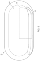
- FIG. 5 illustrates a top view of an exemplary drug delivery device 500.
- the drug delivery device 500 can include an upper portion 502.
- the upper portion 502 can be a top portion or a cover of the drug delivery device 500.
- the drug delivery device 500 can further include a raised portion 504.
- the raised portion 504 can be elongated and can run along a side of the drug delivery device 500.
- a container for holding a liquid drug can be approximately positioned under the raised portion 504 such that the raised portion 504 accommodates the size and positioning of the liquid drug container within the drug delivery device 500.
- a container such as the drug container 102 can be positioned under the raised portion 504. Any drug delivery system described herein can be positioned within the drug delivery device 500.
- the upper portion 502 of the drug delivery device 500 can include a window or viewing area 506.
- the window 506, for Embodiment can be made of plastic and can be transparent.
- the window 506 can be of any size and shape and can be positioned on any portion of the drug delivery device 500.
- the window 506 can allow a patient to view internal components of the drug delivery device 500 such as, for Embodiment, a portion of the drug container positioned within the drug delivery device 500 (e.g., under a portion of the raised portion 504) and/or a portion of the drive mechanism coupled to the drug container.
- the patient can determine how much liquid drug is in an internal drug container by viewing the drug container through the window 506.
- the spherical elements 204 can be differently colored to indicate a dosing status of the liquid drug 104 (and/or a fill status of the drug container 102).
- the window 506 can be positioned on the upper portion 502 to allow a user to view all or a portion of the drug container 102.
- the spherical elements 204 can be driven into the drug container 102 as the spherical elements 204 push on the plunger 106.
- the user can view the spherical elements 204 enter the drug cartridge 102.
- the spherical elements 204 can be colored differently (or marked or otherwise visually distinguished) in a predetermined sequence or manner to indicate how much of the liquid drug 104 has been expelled from the drug container 102.
- the marking or coloring of the spherical elements 204 can be adjusted based on the size of a dose of the liquid drug 104 or an entire amount of liquid drug 104 stored in the drug container 102.
- an initial set of spherical elements 204 can be marked in a first manner (e.g., by a first color such as green) to indicate an initial expulsion of the liquid drug 104 when the initial set of spherical elements 204 enter the drug container 102 and can be viewed.
- An intermediate set of spherical elements 204 can be marked in a second manner (e.g., by a second color such as yellow) to indicate an intermediate expulsion of the liquid drug 104 when the intermediate set of spherical elements 204 enter the drug container 102 and can also be viewed.
- a final set or final spherical element 204 can be marked in a third manner (e.g., by a third color such as red) to indicate a final expulsion of the liquid drug 104 (e.g., end of dose or completion of dose) when the final set or final spherical element 204 enters the drug container 102 and is visible to the user through the window 506.
- a third color such as red
- any type of marking e.g., coloring
- any number of groupings and corresponding distinctions e.g., number of intervals or gradations
- any drive mechanism component used to drive the plunger 106 - including, for Embodiment, a push rod, one or more cylinders, and/or one or more springs - that enters the drug container 102 can be marked in a manner to indicate dosing status or fill status of the drug container 102 based on the extent to which any portion of the drive mechanism component has entered the drug container 102. Further, any marking or coloring of any component of the drive system can be based on a predetermined dose size and/or a total amount of the liquid drug 104 stored in the drug container 102. In various embodiments, the drive mechanism component or components can be marked to simply indicate a completion of a dose - for Embodiment, when a red colored portion of the drive mechanism is visible in the drug container 102, dose completion can be indicated.
- a sensor can be positioned adjacent to the drug container 102 that can track or a count a number of the spherical elements 204 or other drive system components that enter the drug container 102 to provide an indication of dosing status or fill status of the drug container 102.
- a sensor can be positioned adjacent to a first end 112 of the drug container 102.
- the sensor can mechanically or can electromechanically count a number of the spherical elements 204 that pass the sensor as the spherical elements 204 enter the drug container 102.
- the sensor can be a switch that is triggered each time a spherical element 204 passes the sensor.
- the switch could be implemented as a mechanical switch or can be implemented as an electromechanical switch.
- the sensor can be coupled to a display (e.g., an LED display) for indicating dosing status or fill status of the drug container 102.
- a display e.g., an LED display
- a mechanical implementation can include a wheel that has different colors or symbols indicating dose status that can be rotated by the passing of the spherical elements 204.
- FIG. 6 illustrates a third exemplary drug delivery system 600.
- the drug delivery system 600 can include features of the drug delivery system 200 and can further include a dosing wheel 602.
- the dosing wheel 602 can include a number of arms or spokes 604 that radially extend from a hub.
- the dosing wheel 602 can have any number of arms 604.
- One or more of the arms 604 can be positioned between adjacent spheres 204.
- the dosing wheel 602 can rotate in a direction 606 as shown about an axis of the dosing wheel 602 to move the spheres 204 forward toward the drug container 102.
- the drive spring 202 can provide the force to move the spheres 204 as regulated by the dosing wheel 602.
- the drug delivery device 600 can operate as a single dose or multiple dose drug delivery device by regulating movement of the spheres 204.
- movement of the dosing wheel 602 can trigger a counter or other device to track rotational movement of the dosing wheel 602.
- a counter coupled to the dosing wheel 602 can track the number of times the dosing wheel 602 has advanced a single sphere 204 forward. In doing so, the counter can provide the patient with an indication of how much liquid drug 104 has been delivered.
- the counter can be coupled to the dosing wheel 602 mechanically.
- the counter can be coupled to a gear system of the dosing wheel 602 and/or can be arranged to be triggered by contact with the arms 604 as the arms 604 rotate.
- the dosing wheel 602 can be coupled to a controller (not shown in FIG. 6 ) that can track the rotational movement of the dosing wheel 602 and can provide an indication of the filling status of the drug container 102 to the patient.
- the drug delivery system 600 can be housed within a device (e.g., the drug delivery device 500) having a window 608 (shown in phantom).
- the window 608 can enable a user to view a portion of the dosing wheel 602, a portion of the drug container 102, and/or a position of the plunger 106 within the drug container 102.
- the window 608 can be positioned over a portion of the dosing wheel 602 to allow the patient to view the rotation of the arms 604.
- the arms 604 of the dosing wheel 602 can be differently colored (e.g., color coded) or otherwise distinguished visually (e.g., by text or other symbols or markings) to indicate how far the dosing wheel 602 has rotated, thereby providing an indication of how far the plunger 106 has advanced into the drug container 102.
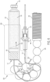
- FIG. 7 illustrates an optical monitoring system 700 for determining the amount of liquid drug stored in a drug container.
- the optical monitoring system 700 includes a printed circuit board (PCB) 702, a drug container 704, a plunger 706, an attenuating light pipe 708, a non-attenuating light pipe 710, a light emitting source 712, and a detector 714.
- PCB printed circuit board
- the drug container 704 can be positioned adjacent to the PCB 102 and can store a liquid drug or other therapeutic agent.
- the plunger 706 can be positioned within the drug container 704 and can be used to expel the liquid drug from the drug container 704.
- the plunger 706 can include a head portion 716 and a base or rod portion 718.
- the rod 718 can extend out of the drug container 704.
- a drive mechanism (not shown in FIG. 7 ) can drive the plunger 706 in a direction 720 to expel stored liquid drug from the drug container 704 for delivery to a patient.
- the plunger can include a reflective portion 722 such as, for Embodiment, a reflective O-ring.
- the reflective O-ring 722 can be positioned on the head portion 716 of the plunger 706.
- the reflective portion 722 can reflect light that is incident on the plunger 706.
- the light emitting source 712 can be a light emitting diode (LED).
- the detector 714 can be a photodiode.
- the non-attenuating light pipe 710 can be positioned on top of the attenuating light pipe 708.
- the attenuating light pipe 708 can be coupled to the light emitting source 712.
- the light pipes 708 and 710 can be positioned adjacent to the drug container 704.
- the attenuating light pipe 708 can be configured to emit light from the light emitting source 712 out of the attenuating light pipe 708.
- the non-attenuating light pipe 710 can be configured to receive light reflected off the reflective portion 722 and to provide the received light to the detector 714.
- the attenuating light pipe 708 can be configured to emit light from the attenuating light pipe at a first angle and the non-attenuating light pipe 710 can be configured to receive light from a second angle that is orthogonal to the first angle.
- the first and second angles are not limited to being orthogonal to one another.
- the first and second angles can be acute or obtuse to one another.
- the first and second angles can be oriented to adjust the effective intensity of light energy received by the non-attenuating light pipe 710.
- the light emitting source 712 can emit light and provide emitted light into the attenuating light source 708. Light provided to the attenuating light pipe 708 from the light emitting source 712 can then be emitted from the attenuating light pipe 708.
- the attenuating light pipe 708 can be configured to attenuate the light it receives along the length of the attenuating light pipe 708. Specifically, light emitted from the attenuating light pipe 708 that is further from the light emitting source 712 can be attenuated more than light emitted from the attenuating light pipe 708 that is closer to the light emitting source 712.
- the non-attenuating light pipe 710 is not specifically configured to attenuate light within the non-attenuating light pipe 710.
- the non-attenuating light pipe 710 can be coupled to the detector 714 such that light received by the non-attenuating light pipe 710 can be provided to the detector 714.
- a reflector 724 can be positioned between the attenuating light pipe 708 and the non-attenuating light pipe 710.
- the reflector 724 can be positioned over a top surface of the attenuating light pipe 708 and below a button surface of the non-attenuating light pipe 710.
- the reflector 724 can prevent light from passing between the attenuating light pipe 708 and the non-attenuating light pipe 710 (e.g., directly passing).
- the reflector 714 can be a film or painted component positioned between the attenuating light pipe 708 and the non-attenuating light pipe 710 or provided on a surface of one of the attenuating light pipe 708 and the non-attenuating light pipe 710.
- the light emitting source 712 can provide a stable source of light to the attenuating light pipe 708.
- the light provided to the attenuating light pipe 708 can be emitted from the attenuating light pipe 708 along the length of the attenuating light pipe 708.
- the emitted light can illuminate the internal portion of the drug container 704 and the plunger 706.
- a portion of the light that enters the drug container 704 from the attenuating light pipe 708 can be reflected by the reflective portion 722. This reflected light can then be received by the non-attenuating light pipe 710.
- the light received by the non-attenuating light pipe 710 can then be provided to the detector 714.
- the detector 714 can determine an intensity of the light received or provided to the detector 714.
- the detector 714 can generate a signal based on the intensity of light received.
- the intensity of the reflected light can vary linearly with the movement of the plunger 706 based on the characteristics of the attenuating light pipe 708.
- the detector 714 can detect the changing intensity of the received light that is reflected off the reflective portion 722. Based on the intensity of the received light, the detector 714 can determine a position of the reflective portion 722 and therefore the plunger 706 within the drug container 704.
- a determination of how much liquid drug remains in the drug container can be made. Further, the measured signals from the detector 714 can be used to determine a rate of movement of the plunger 706. Depending on the movement of the plunger 706 relative to the light emitting source 712, the intensity of the light detected by the detector 714 can increase or decrease as the plunger 706 advances further into the drug container 704.
- the optical monitoring system 700 is arranged to provide relatively lower attenuated light to the detector 714 when the plunger 706 is positioned closer to the light source 712 (and to provide relatively higher attenuated light to the detector 714 when the plunger 706 is positioned closer to the detector 714).
- the intensity of the light provided to the detector 714 will increase as the plunger 706 is advanced to expel additional liquid drug from the drug container 704.
- the optical monitoring system 700 is not limited to this arrangement. In various embodiments, the optical monitoring system 700 can be arranged such that the intensity of the light provided to the detector 714 will decrease as the plunger 706 is advanced to expel additional liquid drug from the drug container 704.
- the optical monitoring system 700 can be arranged to provide light to the detector 714 that varies in intensity based on movement of the plunger 706 (e.g., advancement of the plunger 706 to expel the liquid drug).
- a controller (not shown in FIG. 7 ) coupled to the detector 714 can detect a position of the plunger 706 based on the signals generated by the detector 714 that indicate the intensity of light received by the detector 714.
- the optical monitoring system 700 can be used with any drug container storing a liquid drug that is expelled by any linear translating component having a reflective portion.
- the drug container 102 and the plunger 106 can be used in the optical monitoring system 700.
- any portion of the plunger 706 can be reflective including any component coupled to the plunger 706 that moves with the plunger 706 to expel a stored liquid drug.
- the drug container 704 used with the optical monitoring system can be a transparent container (or a portion thereof can be transparent).
- the optical monitoring system 700 can use any type of radiation emitting/detecting pair such as, for Embodiment, an infrared, a visible light, or an ultraviolet source of radiation and corresponding detector.
- the optical monitoring system 700 can include a controller (not shown in FIG. 7 ) that can be coupled to the light emitting source 712 and the detector 714.
- the controller can be configured to control operation of the light emitting source 712 and/or the detector 714.
- Signals generated by the detector - for Embodiment, signals indicating a position of the plunger 706 based on a detected intensity of reflected light received - can be provided to the controller.
- the controller can subsequently determine a position and movement of the plunger 706 or any component of the drive system for operating the plunger 706 based on signals generated by the detector 714. The controller can further determine how much liquid drug has been expelled and/or how much liquid drug remains in the drug container 704.
- FIG. 8 illustrates an exemplary arrangement of the attenuating light pipe 708 and the non-attenuating light pipe 710 depicted in FIG. 7 .
- the attenuating light pipe 708 and the non-attenuating light pipe 710 can each include windows 808 for emitting light and receiving light, respectively.
- Certain windows 808 can be covered with an anti-reflective (e.g., non-transmissive) coating 802 such that no light is emitted or received through a window 808 coated with anti-reflective coating 802.
- an anti-reflective coating 802 such that no light is emitted or received through a window 808 coated with anti-reflective coating 802.
- the anti-reflective coating 802 can be placed on the windows 808 that are oriented at a first angle relative to the light emitted by the light emitting source 712. As such, as shown in FIG. 8 , light can only be passed through those windows 808 that are not covered by the anti-reflective coating 802.
- the windows 808 of the attenuating light pipe 708 that can pass light can be oriented at a second angle that is orthogonal to the first angle as shown.
- Indicator 804 shows an exemplary direction of light that can be emitted or passed from the attenuating light pipe 708.
- the anti-reflective coating 802 can be placed on windows 808 that are orthogonal to the windows 808 of the attenuating light pipe 708 that are coated with the anti-reflective coating 802 as shown in FIG. 8 . Accordingly, the non-attenuating light pipe 710 can receive light through windows 808 that are orthogonal to the windows 808 of the attenuating light pipe 708 that can emit light, but are not so limited. That is, the windows 808 of the attenuating light pipe 708 that emit light can be oriented according to any angle with respect to the windows 808 of the non-attenuating light pipe 710.
- the windows 808 for emitting and receiving light can be oriented at an obtuse or an acute angle with respect to one another.
- the angle of orientation can be adjusted to provide a desired effective intensity for the light energy received by the non-attenuating light pipe 710.
- Indicator 806 shows an exemplary direction of light that can be received by the non-attenuating light pipe 710.
- the arrangement of the windows 808 and the coated windows 802 of the attenuating light pipe 708 and the non-attenuating light pipe 710 can ensure that attenuated light emitted by the attenuating light pipe 708 is directed toward the detector 714 after it reflects off the plunger 706.
- reflected light from the plunger 706 can pass through an uncoated window 808 of the non-attenuating light pipe 710 and then directed toward the detector 714.
- FIG. 9 illustrates an exemplary arrangement of the attenuating light pipe 708 depicted in FIGs. 7 and 8 .
- Emitted light 902 represents the light emitted from the light emitting source 712 and its intensity (e.g., as indicated by a size of the corresponding arrow representing the light).
- the emitted light 902 can travel down the attenuating light pipe 708 and can exit from windows 808 that are not covered with coating 802.
- Emitted light 904-1 through 904-5 represents the light that passes through each corresponding window 808 and its intensity.
- the attenuating light pipe 708 can be configured to have an attenuation profile that attenuates the emitted light 902 more the further the light is from the light emitting source 712 (e.g., compare the relatively higher intensity of the emitted light 904-1 to the relatively lower intensity emitted light 904-5). Accordingly, the intensity of the light that is emitted from the windows 808 that are closer to the light emitting source 712 - such as, emitted light 904-1 - can be greater than the intensity of the light that is emitted from the windows 808 that are further from the light emitting source 712 - such as, emitted light 904-5.
- the different levels of intensities of the emitted light 904-1 through 904-5 can be reflected off the reflective portion 722 of the plunger 706 as the plunger 706 advances into the drug container 704 and moves along the length of the attenuating light pipe 708 as described above.
- the intensity of the light received by the detector 714 can change (e.g., increase or decrease as the plunger 706 moves further into the drug container 704 depending upon the arrangement of the components of the optical monitoring system 700).
- the varying intensity of the light received by the detector 714 can be used to determine a position of the plunger 706.
- the emitted light 904-1 when reflected off of the reflective portion 722 and then received by the non-attenuating light pipe 710 and the detector 714, can indicate a first position of the plunger 706.
- emitted light 904-5 when reflected off of the reflective portion 722 and then received by the non-attenuating light pipe 710 and the detector 714, can indicate a second, different position of the plunger 706.
- the detector 714 can generate a signal indicative of the intensity of the received light. The signal can be provided to the controller that can then use the signal to determine a position and/or movement of the plunger 706.
- the fill status of the drug container 704 (e.g., how much liquid drug remains in the drug container 704 or has been expelled) can then be determined.
- the attenuating light pipe 708 can be configured to have any attenuation profile. In various embodiments, the attenuating light pipe 708 can be configured to have a linear attenuation profile.
- the attenuating light pipe 708 can be formed of a material having a homogenous attenuation profile that can scatter and/or absorb light to cause attenuation. In general, as light travels further into the attenuation light pipe 708, more attenuation is provided, thereby causing larger decreases in intensity in the light as it travels further into the attenuating light pipe 708 (e.g., further away from the light source 712).
- the attenuating light pipe 708 can be made from various types of materials including plastics and can be covered with an attenuation coating or other material. In various embodiments, the attenuating light pipe 708 can be formed from polymethylmethacrylate (PMMA).
- FIG. 10 illustrates an exemplary operation of the optical monitoring system 700.
- the attenuating light pipe 708 is positioned on top of the non-attenuating light pipe 710.
- the reflector 724 is positioned between the attenuating light pipe 708 and the non-attenuating light pipe 710.
- a light beam 1002 is shown entering the attenuating light pipe 708.
- the light beam 1002 can be provided by the light emitting source 712 depicted in FIG. 7 .
- the light beam 1002 can travel along the attenuating light pipe 708 and can exit as an attenuated version of the light beam 1002 from any of the windows 808 that are not coated windows 802.
- the light beam 1002 can exit a first window 1020 along the attenuated light pipe 708 as a first exit light beam 1004.
- the first exit light beam 1004 can be an attenuated version of the light beam 1002.
- the first exit light beam 1004 can be attenuated by a first amount relative to the intensity of the light beam 1002.
- the light beam 1002 can further exit a second window 1022 along the attenuated light pipe 708 as a second exit light beam 1012.
- the second exit light beam 1012 can be also be an attenuated version of the light beam 1002.
- Indicator 1024 can specify a direction of increasing attenuation by the attenuating light pipe 708.
- the attenuating light pipe 708, as described herein can attenuate the light beam 1002 more further along the length of the attenuating light pipe 708 relative to an entry point of the light beam 1002.
- the first exit light beam 1004 can be attenuated less than the second exit light beam 1012.
- the first exit light beam 1004 is shown to be wider than the second exit light beam 1012 to represent that the second exit light beam 1012 is more attenuated than the first exit light beam 1004.
- the second exit light beam 1012 can be attenuated by a second amount relative to the intensity of the light beam 1002.
- Object 1006 can represent a first position of the plunger 706 (and/or a position of any reflective portion of the plunger 706). As shown in FIG. 10 , the first exit light beam 1004 is reflected off the object 1006 as a first reflective light beam 1008. The first reflective light beam 1008 can pass through any of the windows 808 of the non-attenuating light pipe 710 that are not coated windows 802. The first reflective light beam 1008 can then travel through the non-attenuating light pipe 710 and can be provided to the detector 714 depicted in FIG. 7 .
- Indicator 1010 represents a travel path of the plunger 706. As shown in FIG. 10 , the travel path 1010 of the plunger 706 can be substantially parallel to the arrangement of the attenuating and non-attenuating light pipes 708 and 710.
- Object 1014 can represent a second position of the plunger 706 (and/or a position of any reflective portion of the plunger 706). As shown in FIG. 10 , the second exit light beam 1012 is reflected off the object 1014 as a second reflective light beam 1016. The second reflective light beam 1016 can pass through any of the windows 808 of the non-attenuating light pipe 710 that are not coated windows 802. The second reflective light beam 1016 can then travel through the non-attenuating light pipe 710 and can be provided to the detector 714 depicted in FIG. 7 .
- Light beam 1018 can represent light that exits the non-attenuating light pipe 710 and is provided to the detector 714.
- the light beam 1018 can be an attenuated version of the light beam 1002.
- the level of attenuation experienced by the light beam 1018 can be substantially based on the level of attenuation experienced by the initial light beam 1002 from the attenuating light pipe 708, which is then reflected by the plunger 706.
- the light beam 1018 will experience less attenuation and will be more intense if the plunger 706 is positioned closer to a first end 1024 of the attenuating light pipe 708 in comparison to when the plunger 706 is positioned closer to a second end 1026 of the attenuating light pipe 708.
- the detector 714 can detect the light beam 1018. As described herein, the detector 714 can measure an intensity of the light beam 1018. For Embodiment, the detector 714 can generate a signal based on the measured intensity of the light beam 1018. Signals generated by the detector 714 can be provided to a controller (not shown in FIG. 10 ). The controller can determine a position of the plunger 706 within the drug container 704 based on the signal provided to the controller by the detector 714. For Embodiment, the controller can determine the plunger 706 is positioned closer to the first end 1024 of the attenuating light pipe 708 when the detector 714 generates a signal in response to a relatively more intense light beam 1018.
- the monitoring system 1100 can also include a number of pins 1108.
- the pins 1108 can be positioned within the drug container 1102.
- the pins 1108 can be molded into the drug container 1102.
- the pins 1108 can be made from a conductive material such as a metal.
- the pins 1108 can be positioned and shaped so as to be flush (aligned) or approximately flush with an inner or interior surface of the drug container 1102.
- the pins can also be positioned and shaped so as to be flush (aligned) or approximately flush with an outer or outside surface of the drug container 1102.
- pins 1108 are shown as inserted molded into the drug container 1102 - pins 1108-1 through 1108-7. Any number of pins 1108 can be positioned in the drug container 1102 and can be arranged in any manner.
- the liquid drug 1104 stored in the drug container 1102 can provide electrical conductivity between the pins 1108.
- a controller and/or other circuitry coupled to the pins 1108 can monitor the electrical connectivity of the pins 1108 relative to one another and/or the liquid drug 1106. As the plunger 1106 is moved to expel the liquid drug 1104 from the drug container 1102, a portion of the pins 1108 can become electrically decoupled from the other pins 1108 and/or the liquid drug 1104.
- the controller can monitor the changing status of the electrical connectivity of the pins 1108 to determine a position and/or movement of the plunger 1106. In this way, the monitoring system 1100 can determine a fill status of the drug container 1102 and/or other information regarding dosing rate, an amount of the liquid drug 1104 expelled from the drug container 1102, and/or a rate of movement of the plunger 1106. As shown in FIG. 11 , all of the pins 1108-1 through 1108-7 can be electrically coupled to one another as each pin 1108 is coupled to the liquid drug 1104.
- FIG. 12 illustrates the monitoring system 1100 after a portion of the liquid drug 1104 has been expelled from the drug container 1102.
- the plunger 1106 has moved past the pins 1108-1 through 1108-3 and is positioned adjacent to the pin 1108-4.
- the pins 1108-1 through 1108-4 are no longer coupled to the liquid drug 1104. Consequently, the pins 1108-1 through 1108-4 are no longer electrically connected or coupled to any other pin 1108.
- the controller coupled to the pins 1108 can determine which pins 1108 are electrically coupled together (e.g., and/or coupled to the liquid drug 1104) and can determine a position of the plunger 1104. For Embodiment, as shown in FIG.
- the controller can determine that a front surface of the plunger 1106 (e.g., a surface of the plunger in contact with the liquid drug 1104) can be positioned between the pin 1108-4 and the pin 1108-5.
- the controller can also determine that pins 1108-5 through 1108-7 are electrically connected and coupled to the liquid drug 1104. Accordingly, the monitoring system 1100 allows an approximate position of the plunger 1106 to be determined.
- the monitoring system 110 can determine how much of the liquid drug 1104 remains in the drug container 1102 and how much liquid drug 1104 has been expelled from the drug container 1102.
- the monitoring system 1100 can use number of pins 1108.
- the pins 1108 can be spaced apart from one another by a fixed distance but are not so limited.
- the monitoring system 1100 can use more pins 1108 to provide a better or more accurate approximation as to the location of the plunger 1106 within the drug container (and therefore a better or more accurate approximation of the fill status of the drug container 1102).
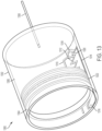
- FIG. 13 illustrates a second exemplary monitoring system 1300.
- the monitoring system 1300 can include a drug container 1302.
- the drug container 1302 can hold or store a liquid drug 1306.
- the monitoring system 1300 can further include a plunger 1304 positioned in the drug container 1302.
- the plunger 1304 can be moved or advanced to expel the liquid drug 1306 from the drug container 1302.
- the drug container 1302 can represent the drug container 102.
- the plunger 1304 can be moved to expel the liquid drug 1306 out of the drug container 1302 through a fluid path 1308 (e.g., by moving toward the fluid path 1308).
- the plunger 1302 and the fluid path 1308 can be arranged to enable the liquid drug 1306 to be expelled through the plunger 1304 (e.g., through an opposite end of the drug container 1302 from what is shown in FIG. 13 ), for Embodiment as described above in relation to FIG. 2 .
- the monitoring system 1300 can further include a first conductive component or trace 1310, a second conductive component or trace 1312, a third conductive component or trace 1314, a first conductive pin 1316, a second conductive pin 1318, and a third conductive pin 1320.
- the traces 1310, 1312, and 1314 and the pins 1316, 1318, and 1320 can be formed of an electrically conductive material.
- a conductive ring or wiper 1322 can be positioned around the plunger 1034.
- the ring 1322 can be formed of an electrically conductive material.
- the first trace 1310 can be coupled to the pin 1318.
- the first trace 1310 can be positioned inside of the drug container 1302.
- the first trace 1310 can be coupled to an inner surface of the drug container 1302.
- the first trace 1310 can extend along a substantial portion of a longitudinal length of the drug container 1302.
- the second trace 1312 can be coupled between the pin 1318 and the pin 1316.
- the second trace can also be coupled to the inner surface of the drug container 1302.
- the second trace can also extend along a substantial portion of the longitudinal length of the drug container 1302.
- the second trace 1312 can be formed of a material having an increasing resistance (e.g., a linearly increasing resistance).
- the third trace 1314 can be coupled to the pin 1316 and the pin 1320.
- the third trace 1314 can be positioned outside of the drug container 1302.
- the third trace 1314 can be coupled to an outer surface of the drug container 1302.
- the third trace 1314 can extend along a substantial portion of the longitudinal length of the drug container 1302.
- the pins 1318 and 1320 can be coupled to one or more output circuits and/or a controller (not shown in FIG. 13 for simplicity).
- the traces 1310, 1312, and 1314, and the pins 1316, 1318, and 1320 can form a variable resistive network.
- the variable resistive network can be used to determine a position of the plunger 1306 within the drug container 1302, enabling a fill status of the drug container 1302 to be determined.
- the ring 1322 electrically couples (e.g., shorts) the trace 1310 to the trace 1312 along different corresponding portions of the traces 1310 and 1312. Coupling the trace 1310 to the trace 1312 completes a circuit.
- the coupling of the trace 1310 to the trace 1312 completes a circuit having different resistance values based on the location of the plunger 1304.
- the completed circuit when the ring 1322 couples the trace 1310 to the trace 1312 at a far end of the drug container 1302 (e.g., in close proximity to the pin 1316), the completed circuit can have a relatively lower resistance, as only a relatively small portion of the trace 1312 is included in the completed circuit (due to the shorting of the traces 1310 and 1312 by the ring 1322).
- the completed circuit can have a relatively higher resistance, as a relatively larger portion of the trace 1312 is included in the completed circuit.
- FIG. 14 illustrates a top view of the monitoring system 1300 depicted in FIG. 13 .
- the arrangement of the traces 1310, 1312, and 1314 along the length of the drug container 1302 is shown. Further, the electrical coupling of the trace 1310 and the trace 1312 by the ring 1322 is illustrated.
- the circuit completed by the ring 1322 includes larger portions of the trace 1312 as the plunger 1304 moves closer to the fluid path 1308. Accordingly, a controller coupled to the output pins 1318 and 1320 can determine the position of the plunger 1304 based on the variable (e.g., increasing) resistance of the completed circuit.
- FIG. 15 illustrates a portion of the monitoring system 1300. Specifically, FIG. 15 illustrates the traces 1310, 1312, and 1314 and the pins 1316, 1318, and 1320. These components can be considered to form a variable resistive network as described above (or a portion of a potentiometer as will be appreciated by a person of ordinary skill in the art).
- the trace 1312 is shown to have a zigzag shape but is not so limited. In various embodiments, the trace 1312 can be a form a substantially straight trace.
- a controller of the monitoring systems can be coupled to a remote user interface device (e.g., a mobile device) and can provide a patient or user with notifications regarding a fill status of a drug container.
- the notification can alert a user to an amount of liquid drug expelled and/or remaining.
- the notification can alert a user to when a desired dose of liquid drug has been provided to a patient and/or when the drug container is empty.
Landscapes
- Health & Medical Sciences (AREA)
- Hematology (AREA)
- Animal Behavior & Ethology (AREA)
- Vascular Medicine (AREA)
- Engineering & Computer Science (AREA)
- Anesthesiology (AREA)
- Biomedical Technology (AREA)
- Veterinary Medicine (AREA)
- Heart & Thoracic Surgery (AREA)
- Life Sciences & Earth Sciences (AREA)
- Public Health (AREA)
- General Health & Medical Sciences (AREA)
- Dermatology (AREA)
- Physics & Mathematics (AREA)
- Fluid Mechanics (AREA)
- General Physics & Mathematics (AREA)
- Infusion, Injection, And Reservoir Apparatuses (AREA)
Claims (12)
- Dispositif portable d'administration de médicaments, comprenant :un récipient de médicament (1102) configuré pour contenir un médicament liquide (1104) ;un piston (1106) positionné dans le récipient de médicament (1102) ;un système d'entraînement couplé au piston (1106), le système d'entraînement étant configuré pour faire avancer le piston (1106) afin d'expulser une partie du médicament liquide (1104) du récipient de médicaments (1102) pour l'administrer à un patient ; etun conduit d'aiguille couplé au récipient de médicament (1102) ou au piston (1106), le conduit d'aiguille étant configuré pour fournir le médicament liquide expulsé (1104) à un patient ; caractérisé par une pluralité de broches conductrices (1108) positionnées dans le récipient de médicament (1102), la pluralité de broches conductrices (1108) pouvant être électriquement couplées au médicament liquide (1104) et espacées le long du récipient de médicament (1102) ; etpar un dispositif de commande couplé électriquement à chacune des broches conductrices (1108), le dispositif de commande étant configuré pour surveiller une connectivité électrique de chacune des broches conductrices (1108).
- Dispositif portable d'administration de médicaments selon la revendication 1, une surface intérieure du récipient de médicaments (1102) étant alignée avec une première surface d'extrémité de chaque broche conductrice (1108).
- Dispositif portable d'administration de médicaments selon la revendication 2, la première surface d'extrémité de chaque broche conductrice (1108) étant disposée à l'intérieur du récipient de médicaments (1102).
- Dispositif portable d'administration de médicaments selon la revendication 2, une surface extérieure du récipient de médicaments (1102) étant alignée avec une deuxième surface d'extrémité de chaque broche conductrice (1108).
- Dispositif portable d'administration de médicaments selon la revendication 4, la deuxième surface d'extrémité de chaque broche conductrice (1108) étant disposée à l'extérieur du récipient de médicaments (1102).
- Dispositif portable d'administration de médicaments selon la revendication 4, la deuxième surface d'extrémité de chaque broche conductrice (1108) étant couplée électriquement au dispositif de commande.
- Dispositif portable d'administration de médicaments selon la revendication 1, la pluralité de broches conductrices (1108) étant positionnée à travers le récipient de médicaments (1102).
- Dispositif portable d'administration de médicaments selon la revendication 1, le dispositif de commande étant configuré pour surveiller une connectivité électrique de chacune de la pluralité de broches conductrices (1108) l'une par rapport à l'autre.
- Dispositif portable d'administration de médicaments selon la revendication 1, le dispositif de commande étant configuré pour surveiller une connectivité électrique de chacune des broches conductrices (1108) par rapport au médicament liquide (1104).
- Dispositif portable d'administration de médicaments selon la revendication 1, le dispositif de commande étant configuré pour déterminer une position du piston (1106) dans le récipient de médicaments (1102) sur la base de la connectivité électrique surveillée de la pluralité de broches conductrices (1108).
- Dispositif portable d'administration de médicaments selon la revendication 10, le dispositif de commande étant configuré pour déterminer un état de remplissage du récipient de médicaments (1102) sur la base de la position déterminée du piston (1106).
- Dispositif portable d'administration de médicaments selon la revendication 1, les broches conductrices (1108) étant régulièrement espacées le long du récipient de médicaments (1102).
Applications Claiming Priority (7)
| Application Number | Priority Date | Filing Date | Title |
|---|---|---|---|
| US201662374881P | 2016-08-14 | 2016-08-14 | |
| US201662375026P | 2016-08-15 | 2016-08-15 | |
| US201662385749P | 2016-09-09 | 2016-09-09 | |
| US201762449845P | 2017-01-24 | 2017-01-24 | |
| US201762449849P | 2017-01-24 | 2017-01-24 | |
| EP17755031.6A EP3496787B1 (fr) | 2016-08-14 | 2017-08-14 | Dispositif d'administration de medicaments aved detection de position du piston |
| PCT/US2017/046777 WO2018035051A1 (fr) | 2016-08-14 | 2017-08-14 | Dispositif d'administration de médicament avec détection de position du piston |
Related Parent Applications (2)
| Application Number | Title | Priority Date | Filing Date |
|---|---|---|---|
| EP17755031.6A Division EP3496787B1 (fr) | 2016-08-14 | 2017-08-14 | Dispositif d'administration de medicaments aved detection de position du piston |
| EP17755031.6A Division-Into EP3496787B1 (fr) | 2016-08-14 | 2017-08-14 | Dispositif d'administration de medicaments aved detection de position du piston |
Publications (2)
| Publication Number | Publication Date |
|---|---|
| EP3730169A1 EP3730169A1 (fr) | 2020-10-28 |
| EP3730169B1 true EP3730169B1 (fr) | 2023-08-02 |
Family
ID=59677455
Family Applications (3)
| Application Number | Title | Priority Date | Filing Date |
|---|---|---|---|
| EP20174878.7A Active EP3730169B1 (fr) | 2016-08-14 | 2017-08-14 | Dispositif d'administration de medicaments avec detection de position du piston |
| EP17757988.5A Withdrawn EP3496789A1 (fr) | 2016-08-14 | 2017-08-14 | Dispositif automatique d'administration de médicament avec mécanisme de déclenchement |
| EP17755031.6A Active EP3496787B1 (fr) | 2016-08-14 | 2017-08-14 | Dispositif d'administration de medicaments aved detection de position du piston |
Family Applications After (2)
| Application Number | Title | Priority Date | Filing Date |
|---|---|---|---|
| EP17757988.5A Withdrawn EP3496789A1 (fr) | 2016-08-14 | 2017-08-14 | Dispositif automatique d'administration de médicament avec mécanisme de déclenchement |
| EP17755031.6A Active EP3496787B1 (fr) | 2016-08-14 | 2017-08-14 | Dispositif d'administration de medicaments aved detection de position du piston |
Country Status (3)
| Country | Link |
|---|---|
| US (5) | US10441723B2 (fr) |
| EP (3) | EP3730169B1 (fr) |
| WO (2) | WO2018035032A1 (fr) |
Families Citing this family (39)
| Publication number | Priority date | Publication date | Assignee | Title |
|---|---|---|---|---|
| EP1762259B2 (fr) | 2005-09-12 | 2025-01-01 | Unomedical A/S | Inserteur pour un équipement d'infusion avec une première et deuxieme unités de ressort |
| WO2012123274A1 (fr) | 2011-03-14 | 2012-09-20 | Unomedical A/S | Système d'insertion doté d'une protection pour son transport |
| EP2583715A1 (fr) | 2011-10-19 | 2013-04-24 | Unomedical A/S | Système de tube de perfusion et procédé de fabrication |
| HUE067982T2 (hu) | 2012-03-30 | 2024-12-28 | Insulet Corp | Folyadékadagoló készülék transzkután beviteli eszközzel, behelyezõ mechanizmussal és vércukor monitorozással |
| WO2015061693A1 (fr) | 2013-10-24 | 2015-04-30 | Trustees Of Boston University | Système de perfusion faisant appel à un ensemble perfusion destiné à prévenir les erreurs de canalisation en cas de multiples médicaments |
| EP3319662B1 (fr) | 2015-07-08 | 2023-09-13 | Trustees of Boston University | Système de perfusion et ses composants |
| WO2017125817A1 (fr) | 2016-01-19 | 2017-07-27 | Unomedical A/S | Canule et dispositifs de perfusion |
| US10363374B2 (en) | 2016-05-26 | 2019-07-30 | Insulet Corporation | Multi-dose drug delivery device |
| EP3730169B1 (fr) | 2016-08-14 | 2023-08-02 | Insulet Corporation | Dispositif d'administration de medicaments avec detection de position du piston |
| WO2018096534A1 (fr) | 2016-11-22 | 2018-05-31 | Sorrel Medical Ltd. | Appareil d'administration d'une substance thérapeutique |
| CN110366405B (zh) | 2017-01-06 | 2023-02-17 | 波士顿大学托管委员会 | 输注系统及其部件 |
| US10603440B2 (en) | 2017-01-19 | 2020-03-31 | Insulet Corporation | Cartridge hold-up volume reduction |
| JP2020524024A (ja) * | 2017-06-20 | 2020-08-13 | バレリタス, インコーポレイテッド | 液圧式薬物送達デバイスのための時間遅延機構 |
| EP4375504B1 (fr) | 2017-08-03 | 2026-04-15 | Insulet Corporation | Pompe à micro-piston |
| US11786668B2 (en) | 2017-09-25 | 2023-10-17 | Insulet Corporation | Drug delivery devices, systems, and methods with force transfer elements |
| CN111902177A (zh) * | 2018-02-05 | 2020-11-06 | 赛诺菲 | 用于注射装置的压力传感器组件和方法 |
| EP3545993A1 (fr) * | 2018-03-29 | 2019-10-02 | Tecpharma Licensing AG | Indicateur d'état pour des systèmes d'administration de médicaments |
| EP3545991A1 (fr) | 2018-03-29 | 2019-10-02 | Tecpharma Licensing AG | Alimentation électrique pour systèmes d'administration de médicaments |
| EP3545992A1 (fr) | 2018-03-29 | 2019-10-02 | Tecpharma Licensing AG | Estimation d'état pour des systèmes d'administration de médicament |
| US10874803B2 (en) | 2018-05-31 | 2020-12-29 | Insulet Corporation | Drug cartridge with drive system |
| US11229736B2 (en) | 2018-06-06 | 2022-01-25 | Insulet Corporation | Linear shuttle pump for drug delivery |
| WO2019241335A1 (fr) * | 2018-06-12 | 2019-12-19 | University Of Massachusetts | Système, procédé et appareil de détection de position électronique |
| WO2020023576A1 (fr) | 2018-07-25 | 2020-01-30 | Modular Medical, Inc. | Raccord pour accès sous-cutané comportant de multiples orifices pour canule |
| EP3744368B1 (fr) | 2018-10-05 | 2026-02-18 | LTS Device Technologies Ltd | Déclenchement de séquence |
| AU2019390474B2 (en) | 2018-11-28 | 2023-03-30 | Insulet Corporation | Drug delivery shuttle pump system and valve assembly |
| EP3972674A4 (fr) * | 2019-05-20 | 2023-02-08 | The University Of Sydney | Adaptateur destiné à un dispositif d'administration de médicament et procédé associé |
| US11458292B2 (en) | 2019-05-20 | 2022-10-04 | Unomedical A/S | Rotatable infusion device and methods thereof |
| IL267610A (en) * | 2019-06-24 | 2019-10-31 | Dali Medical Devices Ltd | dose monitoring |
| WO2021011699A1 (fr) | 2019-07-16 | 2021-01-21 | Beta Bionics, Inc. | Dispositif ambulatoire et composants correspondants |
| US11369735B2 (en) | 2019-11-05 | 2022-06-28 | Insulet Corporation | Component positioning of a linear shuttle pump |
| USD1031975S1 (en) | 2020-03-10 | 2024-06-18 | Beta Bionics, Inc. | Medicament infusion pump device |
| US11278661B2 (en) | 2020-03-10 | 2022-03-22 | Beta Bionics, Inc. | Infusion system and components thereof |
| USD1099024S1 (en) | 2020-03-10 | 2025-10-21 | Beta Bionics, Inc. | Charging device for medicament infusion pump device |
| EP4274640A1 (fr) * | 2021-01-08 | 2023-11-15 | Insulet Corporation | Chambre de pompage intermédiaire à dose de précision à actionnement unique |
| US12440617B2 (en) | 2021-01-11 | 2025-10-14 | Insulet Corporation | Linear activated drug dosing pump system |
| US11419976B1 (en) | 2021-04-30 | 2022-08-23 | Fresenius Kabi Deutschland Gmbh | Wearable drug delivery device with pressurized fluid dispensing |
| US12594376B2 (en) | 2021-05-21 | 2026-04-07 | Insulet Corporation | Compact positive displacement pump for wearable drug delivery device |
| US12359903B2 (en) | 2021-05-28 | 2025-07-15 | Insulet Corporation | Spring-based status sensors |
| US20230414864A1 (en) * | 2022-06-28 | 2023-12-28 | Insulet Corporation | Methods and systems for optical-based fluid control in a fluid delivery system |
Family Cites Families (312)
| Publication number | Priority date | Publication date | Assignee | Title |
|---|---|---|---|---|
| CA606281A (en) | 1960-10-04 | Dann Morris | Cartridge for metering syringe | |
| US1441508A (en) | 1921-12-06 | 1923-01-09 | Jensen Anton Marius | Cylindrical slide valve |
| GB357139A (fr) | 1929-06-14 | 1931-09-14 | Paul Von Vago | |
| US2198666A (en) | 1936-09-30 | 1940-04-30 | Lakeland Foundation | Syringe |
| FR1078911A (fr) * | 1949-08-17 | 1954-11-24 | Seringue hypodermique automatique et son ampoule | |
| GB810488A (en) | 1955-03-01 | 1959-03-18 | Eduard Woydt | Liquid pressure piston-engine or reciprocating pump |
| GB875034A (en) | 1957-07-01 | 1961-08-16 | Renault | Improvements in or relating to valves for fluids under pressure |
| US3176712A (en) | 1961-10-03 | 1965-04-06 | Ramsden Clement | Non-return valve |
| US3297260A (en) | 1964-09-21 | 1967-01-10 | Conrad R Barlow | Nozzle and valve assembly |
| US3464359A (en) | 1967-11-13 | 1969-09-02 | Medimeter Corp The | Apparatus for moving fluid from one system to a second system |
| US3505809A (en) | 1968-05-20 | 1970-04-14 | Thermal Hydraulics Corp | Thermal motor |
| DE7121836U (de) | 1970-06-13 | 1972-01-27 | Ismatec Sa | Dosier-kolbenpumpe |
| US3946732A (en) | 1973-08-08 | 1976-03-30 | Ampoules, Inc. | Two-chamber mixing syringe |
| US3885662A (en) | 1973-12-26 | 1975-05-27 | Ibm | Steerable follower selection mechanism |
| US3947692A (en) * | 1974-08-05 | 1976-03-30 | Viron E. Payne, Inc. | Digital transducers |
| IL46017A (en) | 1974-11-07 | 1977-11-30 | Ampoules Inc | Two-chamber mixing syringe |
| US3993061A (en) | 1975-02-28 | 1976-11-23 | Ivac Corporation | Syringe pump drive system and disposable syringe cartridge |
| FR2348709A1 (fr) | 1976-04-23 | 1977-11-18 | Pistor Michel | Procede de traitement mesotherapique et dispositif d'injection,formant micro-injecteur automatique,en comportant application |
| US4210173A (en) | 1976-12-06 | 1980-07-01 | American Hospital Supply Corporation | Syringe pumping system with valves |
| US4152098A (en) | 1977-01-03 | 1979-05-01 | Clark Ivan P | Micropump |
| DE2749251C3 (de) | 1977-11-03 | 1981-10-08 | Danfoss A/S, 6430 Nordborg | Regelbare Heizvorrichtung für kleine Massen, insbesondere das Ausdehnungsmittel in Wärmestellvorrichtungen |
| FR2455269A1 (fr) | 1978-01-17 | 1980-11-21 | Marceau Serge | Systeme de dosage dynamique a cylindres pneumatiques |
| US4221219A (en) | 1978-07-31 | 1980-09-09 | Metal Bellows Corporation | Implantable infusion apparatus and method |
| US4265601A (en) | 1978-09-05 | 1981-05-05 | Harold Mandroian | Three valve precision pump apparatus with head pressure flowthrough protection |
| US4257324A (en) | 1978-10-30 | 1981-03-24 | Bell & Howell Company | Position monitoring methods and apparatus |
| WO1981001658A1 (fr) | 1979-12-13 | 1981-06-25 | M Loeb | Systeme d'injection d'insuline portable par le patient possedant un reservoir tubulaire, un deplacement positif et un moyen de mesure |
| US4268150A (en) | 1980-01-28 | 1981-05-19 | Laurence Chen | Disposable camera with simplified film advance and indicator |
| US4313439A (en) * | 1980-03-24 | 1982-02-02 | Biotek, Inc. | Automated, spring-powered medicament infusion system |
| CA1169323A (fr) | 1980-06-03 | 1984-06-19 | Anthony M. Albisser | Dispositif de perfusion d'insuline |
| US4371790A (en) * | 1980-09-19 | 1983-02-01 | Rmr Systems, Inc. | Fluid measuring system |
| US4424720A (en) | 1980-12-15 | 1984-01-10 | Ivac Corporation | Mechanism for screw drive and syringe plunger engagement/disengagement |
| US4417889A (en) | 1980-12-31 | 1983-11-29 | Choi Soo Bong | Device for a portable automatic syringe |
| JPS57163309A (en) | 1981-04-01 | 1982-10-07 | Olympus Optical Co Ltd | Capsule apparatus for medical use |
| FR2507637B1 (fr) | 1981-06-16 | 1986-09-26 | Libero Elettrotecnica | Dispositif d'actionnement thermoelectrique, notamment pour activer des distributeurs de detergents et/ou d'agents de brillantage dans des machines a laver |
| US4435173A (en) | 1982-03-05 | 1984-03-06 | Delta Medical Industries | Variable rate syringe pump for insulin delivery |
| US4498843A (en) | 1982-08-02 | 1985-02-12 | Schneider Philip H | Insulin infusion pump |
| US4551134A (en) | 1982-08-06 | 1985-11-05 | Nuvatec, Inc. | Intravenous set |
| US4475905A (en) | 1982-09-30 | 1984-10-09 | Himmelstrup Anders B | Injection device |
| EP0143895B1 (fr) | 1983-09-07 | 1987-12-23 | Disetronic Ag | Dispositif portatif d'infusion |
| NL8303908A (nl) | 1983-11-15 | 1985-06-03 | Unilever Nv | Werkwijze en inrichting voor het volumetrisch doseren van viskeuze produkten. |
| US4685903A (en) | 1984-01-06 | 1987-08-11 | Pacesetter Infusion, Ltd. | External infusion pump apparatus |
| US4562751A (en) | 1984-01-06 | 1986-01-07 | Nason Clyde K | Solenoid drive apparatus for an external infusion pump |
| US4678408A (en) | 1984-01-06 | 1987-07-07 | Pacesetter Infusion, Ltd. | Solenoid drive apparatus for an external infusion pump |
| US4684368A (en) | 1984-06-01 | 1987-08-04 | Parker Hannifin Corporation | Inverted pump |
| US4634427A (en) | 1984-09-04 | 1987-01-06 | American Hospital Supply Company | Implantable demand medication delivery assembly |
| US4567549A (en) | 1985-02-21 | 1986-01-28 | Blazer International Corp. | Automatic takeup and overload protection device for shape memory metal actuator |
| US4908017A (en) | 1985-05-14 | 1990-03-13 | Ivion Corporation | Failsafe apparatus and method for effecting syringe drive |
| US4846797A (en) | 1985-05-14 | 1989-07-11 | Intelligent Medicine, Inc. | Syringe positioning device for enhancing fluid flow control |
| DK160633C (da) | 1985-05-15 | 1991-09-02 | Henning Munk Ejlersen | Slangepumpe, isaer til avendelse som insulinpumpe |
| US4689042A (en) | 1985-05-20 | 1987-08-25 | Survival Technology, Inc. | Automatic medicament ingredient mixing and injecting apparatus |
| US5349852A (en) | 1986-03-04 | 1994-09-27 | Deka Products Limited Partnership | Pump controller using acoustic spectral analysis |
| US4778451A (en) | 1986-03-04 | 1988-10-18 | Kamen Dean L | Flow control system using boyle's law |
| US4766889A (en) | 1986-06-26 | 1988-08-30 | Medical Engineering Corporation | Infusion erectile system |
| GB8701731D0 (en) | 1987-01-27 | 1987-03-04 | Patcentre Benelux Nv Sa | Pumps |
| DE3882202D1 (en) | 1987-05-18 | 1993-08-12 | Disetronic Ag | Infusionsgeraet. |
| US4898579A (en) | 1987-06-26 | 1990-02-06 | Pump Controller Corporation | Infusion pump |
| US4858619A (en) | 1987-06-29 | 1989-08-22 | Toth Marie A | Intracranial pressure monitoring system |
| ATA228987A (de) | 1987-09-09 | 1993-07-15 | Pickhard Ewald | Injektionsvorrichtung mit einer verformbaren ampulle |
| US5062841A (en) | 1988-08-12 | 1991-11-05 | The Regents Of The University Of California | Implantable, self-regulating mechanochemical insulin pump |
| US5222362A (en) | 1989-01-10 | 1993-06-29 | Maus Daryl D | Heat-activated drug delivery system and thermal actuators therefor |
| US5205819A (en) | 1989-05-11 | 1993-04-27 | Bespak Plc | Pump apparatus for biomedical use |
| US4991743A (en) | 1989-11-06 | 1991-02-12 | Cobe Laboratories, Inc. | Controlled flow accumulator |
| US5020325A (en) | 1990-02-13 | 1991-06-04 | Procedes Vernet | Heat motor |
| US5097122A (en) | 1990-04-16 | 1992-03-17 | Pacesetter Infusion, Ltd. | Medication infusion system having optical motion sensor to detect drive mechanism malfunction |
| US5007458A (en) | 1990-04-23 | 1991-04-16 | Parker Hannifin Corporation | Poppet diaphragm valve |
| JPH0451966A (ja) | 1990-06-19 | 1992-02-20 | Toichi Ishikawa | 薬液連続注入器 |
| GB9027859D0 (en) | 1990-12-21 | 1991-02-13 | Cmb Foodcan Plc | Metering apparatus |
| US5236416A (en) | 1991-05-23 | 1993-08-17 | Ivac Corporation | Syringe plunger position detection and alarm generation |
| US5213483A (en) | 1991-06-19 | 1993-05-25 | Strato Medical Corporation | Peristaltic infusion pump with removable cassette and mechanically keyed tube set |
| DE4129271C1 (fr) | 1991-09-03 | 1992-09-17 | Fresenius Ag, 6380 Bad Homburg, De | |
| DE4200595C2 (de) | 1992-01-13 | 1994-10-13 | Michail Efune | Baugruppe zum Infusion-Set für eine Insulinpumpe |
| US5911716A (en) | 1992-01-24 | 1999-06-15 | I-Flow Corporation | Platen pump |
| US5267956A (en) | 1992-02-05 | 1993-12-07 | Alcon Surgical, Inc. | Surgical cassette |
| DK47992D0 (da) | 1992-04-10 | 1992-04-10 | Novo Nordisk As | Apparat |
| US5261884A (en) | 1992-04-29 | 1993-11-16 | Becton, Dickinson And Company | Syringe pump control system |
| US5346476A (en) | 1992-04-29 | 1994-09-13 | Edward E. Elson | Fluid delivery system |
| JPH0663133A (ja) | 1992-06-18 | 1994-03-08 | Raifu Technol Kenkyusho | 携帯用自動薬液注入装置 |
| US6068615A (en) * | 1994-07-22 | 2000-05-30 | Health Hero Network, Inc. | Inductance-based dose measurement in syringes |
| DE4241943C2 (de) | 1992-12-11 | 1994-12-01 | Busak & Luyken Gmbh & Co | Verschlußmittel und Dichtungsventil für Behälteröffnungen |
| CH685461B5 (fr) | 1993-01-05 | 1996-01-31 | Jean Claude Berney | Dispositif portable de perfusion de substances therapeutiques liquides et ensembles comprenant un tel dispositif. |
| US5433710A (en) | 1993-03-16 | 1995-07-18 | Minimed, Inc. | Medication infusion pump with fluoropolymer valve seat |
| DE4310808C2 (de) | 1993-04-02 | 1995-06-22 | Boehringer Mannheim Gmbh | System zur Dosierung von Flüssigkeiten |
| JP3381301B2 (ja) | 1993-04-14 | 2003-02-24 | 株式会社ジェイ・エム・エス | シリンジポンプ |
| US5261882A (en) | 1993-04-26 | 1993-11-16 | Sealfon Andrew I | Negator spring-powered syringe |
| DE69415683T2 (de) | 1993-10-04 | 1999-09-09 | Res International | Mikromaschinen-fluss-schalter |
| US5807075A (en) | 1993-11-23 | 1998-09-15 | Sarcos, Inc. | Disposable ambulatory microprocessor controlled volumetric pump |
| JPH0824832A (ja) | 1994-07-08 | 1996-01-30 | Takamichi Iida | 無機質繊維フィルター廃材処理方法 |
| US5582593A (en) | 1994-07-21 | 1996-12-10 | Hultman; Barry W. | Ambulatory medication delivery system |
| US5520661A (en) | 1994-07-25 | 1996-05-28 | Baxter International Inc. | Fluid flow regulator |
| CA2154937A1 (fr) | 1994-07-29 | 1996-01-30 | John C. Tanner | Systeme pour l'administration d'un agent liquide a un patient a l'aide d'une pompe a seringue |
| JPH0858897A (ja) | 1994-08-12 | 1996-03-05 | Japan Storage Battery Co Ltd | 流体供給装置 |
| US5637095A (en) | 1995-01-13 | 1997-06-10 | Minimed Inc. | Medication infusion pump with flexible drive plunger |
| US5665070A (en) | 1995-01-19 | 1997-09-09 | I-Flow Corporation | Infusion pump with magnetic bag compression |
| JP2697663B2 (ja) | 1995-03-04 | 1998-01-14 | 株式会社ニッショー | 複数薬液混注具 |
| FR2731475B1 (fr) | 1995-03-07 | 1997-05-30 | Thomson Dauphinoise | Dispositif de montage d'un composant electrique de chauffage et/ou de refroidissement sur un verin thermique |
| US5503628A (en) | 1995-03-15 | 1996-04-02 | Jettek, Inc. | Patient-fillable hypodermic jet injector |
| DK0821566T3 (da) | 1995-04-20 | 2004-01-26 | Acist Medical Sys Inc | Angiografisk injektor |
| US5618269A (en) | 1995-05-04 | 1997-04-08 | Sarcos, Inc. | Pressure-driven attachable topical fluid delivery system |
| DE69620569T2 (de) | 1995-07-27 | 2002-10-31 | Seiko Epson Corp., Tokio/Tokyo | Mikroventil und methode zu dessen herstellung, mikropumpe die dieses mikroventil benutzt und methode zu ihrer herstellung, sowie vorrichtung, die diese mikropumpe verwendet |
| US5702488A (en) | 1995-09-12 | 1997-12-30 | Model & Instrument Development Corporation | Prosthetic pylon having an enclosed compressible volume of fluid to support a patient's weight |
| US5776103A (en) | 1995-10-11 | 1998-07-07 | Science Incorporated | Fluid delivery device with bolus injection site |
| US5779676A (en) | 1995-10-11 | 1998-07-14 | Science Incorporated | Fluid delivery device with bolus injection site |
| US6050457A (en) | 1995-12-06 | 2000-04-18 | The Procter & Gamble Company | High pressure manually-actuated spray pump |
| US5628309A (en) | 1996-01-25 | 1997-05-13 | Raya Systems, Inc. | Meter for electrically measuring and recording injection syringe doses |
| GB9606829D0 (en) | 1996-03-30 | 1996-06-05 | Jeffrey Peter | Supplying materials etc |
| US5976109A (en) | 1996-04-30 | 1999-11-02 | Medtronic, Inc. | Apparatus for drug infusion implanted within a living body |
| US5785688A (en) | 1996-05-07 | 1998-07-28 | Ceramatec, Inc. | Fluid delivery apparatus and method |
| IL118689A (en) | 1996-06-20 | 2000-10-31 | Gadot Amir | Intravenous infusion apparatus |
| US5748827A (en) | 1996-10-23 | 1998-05-05 | University Of Washington | Two-stage kinematic mount |
| US6883778B1 (en) | 1996-11-18 | 2005-04-26 | Nypro Inc. | Apparatus for reducing fluid drawback through a medical valve |
| KR0138353Y1 (ko) | 1996-12-13 | 1999-04-01 | 주식회사부윤테크 | 일회용 주사기 |
| CH692240A5 (de) | 1997-03-26 | 2002-04-15 | Disetronic Licensing Ag | Kathetersystem für Hautdurchlassvorrichtungen. |
| CN1179983A (zh) | 1997-06-03 | 1998-04-29 | 王坤山 | 由弹性活门式瓶塞和穿刺针组成的医用装置 |
| DE19723648C1 (de) | 1997-06-05 | 1998-08-27 | Disetronic Licensing Ag | Vorrichtung zur dosierten Verabreichung einer Medikamentflüssigkeit |
| US5957890A (en) | 1997-06-09 | 1999-09-28 | Minimed Inc. | Constant flow medication infusion pump |
| US5954643A (en) | 1997-06-09 | 1999-09-21 | Minimid Inc. | Insertion set for a transcutaneous sensor |
| US5961492A (en) | 1997-08-27 | 1999-10-05 | Science Incorporated | Fluid delivery device with temperature controlled energy source |
| US6527744B1 (en) | 1997-08-27 | 2003-03-04 | Science Incorporated | Fluid delivery device with light activated energy source |
| US6485462B1 (en) | 1997-08-27 | 2002-11-26 | Science Incorporated | Fluid delivery device with heat activated energy source |
| US6200293B1 (en) | 1997-08-27 | 2001-03-13 | Science Incorporated | Fluid delivery device with temperature controlled energy source |
| US6569115B1 (en) | 1997-08-28 | 2003-05-27 | Mdc Investment Holdings, Inc. | Pre-filled retractable needle injection device |
| WO1999010049A1 (fr) | 1997-08-29 | 1999-03-04 | Cycle-Ops Products, Inc. | Dispositif de resistance pour appareil d'exercice physique |
| US6019747A (en) | 1997-10-21 | 2000-02-01 | I-Flow Corporation | Spring-actuated infusion syringe |
| US5897530A (en) | 1997-12-24 | 1999-04-27 | Baxter International Inc. | Enclosed ambulatory pump |
| US6159188A (en) | 1998-01-14 | 2000-12-12 | Robert L. Rogers | Apparatus and method for delivery of micro and submicro quantities of materials |
| US6539286B1 (en) * | 1998-01-26 | 2003-03-25 | Micron Technology, Inc. | Fluid level sensor |
| AU2570999A (en) | 1998-02-02 | 1999-08-16 | Medtronic, Inc. | Implantable drug infusion device having a safety valve |
| WO1999048546A1 (fr) | 1998-03-23 | 1999-09-30 | Elan Corporation, Plc | Dispositif d'administration de medicament |
| US5919167A (en) | 1998-04-08 | 1999-07-06 | Ferring Pharmaceuticals | Disposable micropump |
| EP1082151A1 (fr) | 1998-06-04 | 2001-03-14 | ELAN CORPORATION, Plc | Dispositif d'administration de medicament a commande a gaz |
| US5906597A (en) | 1998-06-09 | 1999-05-25 | I-Flow Corporation | Patient-controlled drug administration device |
| US5993423A (en) | 1998-08-18 | 1999-11-30 | Choi; Soo Bong | Portable automatic syringe device and injection needle unit thereof |
| KR20010081028A (ko) | 1998-11-18 | 2001-08-25 | 추후제출 | 제어 또는 프로그래밍을 위한 데이터의 무선 전송으로약제를 이동식으로 공급하는 휴대용 장치 및 방법 |
| US6375638B2 (en) | 1999-02-12 | 2002-04-23 | Medtronic Minimed, Inc. | Incremental motion pump mechanisms powered by shape memory alloy wire or the like |
| US20040069044A1 (en) | 1999-04-29 | 2004-04-15 | Gilad Lavi | Device for measuring a volume of drug |
| JP2003501156A (ja) | 1999-06-08 | 2003-01-14 | メディカル リサーチ グループ インコーポレイテッド | 埋め込み可能な注入デバイスにおける化学反応を利用した液体の注入法およびその装置 |
| IL147302A0 (en) | 1999-06-28 | 2002-08-14 | California Inst Of Techn | Microfabricated elastomeric valve and pump systems |
| US6648821B2 (en) | 2000-01-21 | 2003-11-18 | Medtronic Minimed, Inc. | Microprocessor controlled ambulatory medical apparatus with hand held communication device |
| US7003336B2 (en) | 2000-02-10 | 2006-02-21 | Medtronic Minimed, Inc. | Analyte sensor method of making the same |
| US6685678B2 (en) | 2000-03-22 | 2004-02-03 | Docusys, Inc. | Drug delivery and monitoring system |
| TW523415B (en) | 2000-03-24 | 2003-03-11 | Novo Nordisk As | A flexible piston rod |
| US6485461B1 (en) | 2000-04-04 | 2002-11-26 | Insulet, Inc. | Disposable infusion device |
| US6585699B2 (en) | 2000-04-13 | 2003-07-01 | Nna/S | Drug delivery device provided with a one-way mechanism |
| US6494433B2 (en) | 2000-06-06 | 2002-12-17 | The Regents Of The University Of Michigan | Thermally activated polymer device |
| US6589229B1 (en) | 2000-07-31 | 2003-07-08 | Becton, Dickinson And Company | Wearable, self-contained drug infusion device |
| JP2004521667A (ja) | 2000-09-08 | 2004-07-22 | インシュレット コーポレイション | 患者の輸液のための装置、システム及び方法 |
| US6363609B1 (en) | 2000-10-20 | 2002-04-02 | Short Block Technologies, Inc. | Method and apparatus for aligning crankshaft sections |
| US6644944B2 (en) | 2000-11-06 | 2003-11-11 | Nanostream, Inc. | Uni-directional flow microfluidic components |
| DE60126325T2 (de) | 2000-11-09 | 2007-11-08 | Insulet Corp., Beverly | Gerät zur transkutanen abgabe von medikamenten |
| US6537249B2 (en) | 2000-12-18 | 2003-03-25 | Science, Incorporated | Multiple canopy |
| WO2002057627A1 (fr) | 2001-01-17 | 2002-07-25 | M 2 Medical A/S | Actionneur en alliage a memoire de forme |
| GB0107601D0 (en) | 2001-03-27 | 2001-05-16 | Dca Design Int Ltd | Improvements in and relating to and injection device |
| EP2140891B1 (fr) | 2001-05-18 | 2013-03-27 | DEKA Products Limited Partnership | Conduit de couplage pour un dispositif distributeur de fluide |
| US7235063B2 (en) | 2001-08-21 | 2007-06-26 | D'antonio Consultants International, Inc. | Hypodermic injection system |
| US20040094733A1 (en) | 2001-08-31 | 2004-05-20 | Hower Robert W. | Micro-fluidic system |
| US20030055380A1 (en) | 2001-09-19 | 2003-03-20 | Flaherty J. Christopher | Plunger for patient infusion device |
| NL1019126C1 (nl) | 2001-10-05 | 2003-04-08 | Fondse Valves B V | Doseerpomp. |
| US20040078028A1 (en) | 2001-11-09 | 2004-04-22 | Flaherty J. Christopher | Plunger assembly for patient infusion device |
| US20030109827A1 (en) | 2001-12-07 | 2003-06-12 | Elan Pharma International Limited | Drug delivery system and method |
| US6878136B2 (en) | 2002-02-28 | 2005-04-12 | Medical Product Specialists | Huber needle with anti-rebound safety mechanism |
| AU2003216521A1 (en) | 2002-03-18 | 2003-10-08 | Eli Lilly And Company | Medication dispensing apparatus with gear set for mechanical advantage |
| CN1375338A (zh) | 2002-03-22 | 2002-10-23 | 张�浩 | 加热式输液器 |
| US7104275B2 (en) | 2002-04-01 | 2006-09-12 | Emerson Electric Co. | Pinch valve |
| US7052251B2 (en) | 2002-04-22 | 2006-05-30 | Medtronic Minimed, Inc. | Shape memory alloy wire driven positive displacement micropump with pulsatile output |
| US6656159B2 (en) | 2002-04-23 | 2003-12-02 | Insulet Corporation | Dispenser for patient infusion device |
| US6960192B1 (en) | 2002-04-23 | 2005-11-01 | Insulet Corporation | Transcutaneous fluid delivery system |
| US20050238507A1 (en) | 2002-04-23 | 2005-10-27 | Insulet Corporation | Fluid delivery device |
| US20040153032A1 (en) | 2002-04-23 | 2004-08-05 | Garribotto John T. | Dispenser for patient infusion device |
| US6656158B2 (en) | 2002-04-23 | 2003-12-02 | Insulet Corporation | Dispenser for patient infusion device |
| GB0211294D0 (en) | 2002-05-17 | 2002-06-26 | Owen Mumford Ltd | Improvements relating to injection devices |
| US7160272B1 (en) | 2002-05-31 | 2007-01-09 | Elcam Plastic | Y-site medical valve |
| US6723072B2 (en) | 2002-06-06 | 2004-04-20 | Insulet Corporation | Plunger assembly for patient infusion device |
| US20040010207A1 (en) | 2002-07-15 | 2004-01-15 | Flaherty J. Christopher | Self-contained, automatic transcutaneous physiologic sensing system |
| US7018360B2 (en) | 2002-07-16 | 2006-03-28 | Insulet Corporation | Flow restriction system and method for patient infusion device |
| US6749407B2 (en) | 2002-08-22 | 2004-06-15 | Motorola, Inc. | Method of installing valves in a micro-pump |
| EP1403519A1 (fr) | 2002-09-27 | 2004-03-31 | Novo Nordisk A/S | Pompe à membrane avec membrane extensible |
| US7128727B2 (en) | 2002-09-30 | 2006-10-31 | Flaherty J Christopher | Components and methods for patient infusion device |
| US7144384B2 (en) | 2002-09-30 | 2006-12-05 | Insulet Corporation | Dispenser components and methods for patient infusion device |
| US20040068224A1 (en) | 2002-10-02 | 2004-04-08 | Couvillon Lucien Alfred | Electroactive polymer actuated medication infusion pumps |
| US7399401B2 (en) | 2002-10-09 | 2008-07-15 | Abbott Diabetes Care, Inc. | Methods for use in assessing a flow condition of a fluid |
| AU2003279237A1 (en) | 2002-10-09 | 2004-05-04 | Therasense, Inc. | Fluid delivery device, system and method |
| DE60319142T2 (de) | 2002-12-23 | 2009-02-05 | M2 Medical A/S | Medizinische Vorrichtung zur Abgabe von Insulin |
| JP2004247271A (ja) | 2003-02-12 | 2004-09-02 | Bimetal Japan Kk | 電圧感知スイッチ. |
| JP2004274719A (ja) | 2003-02-18 | 2004-09-30 | Fujitsu Hitachi Plasma Display Ltd | プリドライブ回路、容量性負荷駆動回路及びプラズマディスプレイ装置 |
| CN101410146A (zh) | 2003-04-18 | 2009-04-15 | 因苏雷特公司 | 输液泵遥控器的用户接口及其使用方法 |
| JP2007511252A (ja) | 2003-06-09 | 2007-05-10 | ニプロ ダイアビティーズ システムズ,インコーポレイテッド | 注入ポンプにおけるカップリングシステム |
| DE10327254B4 (de) | 2003-06-17 | 2010-01-28 | Disetronic Licensing Ag | Modulare Infusionspumpe |
| JP4047803B2 (ja) | 2003-12-25 | 2008-02-13 | 日機装株式会社 | ダイアフラムポンプ |
| CA2559083C (fr) | 2004-03-08 | 2015-06-16 | Ichor Medical Systems, Inc. | Appareil ameliore pour une administration electriquement mediee d'agents therapeutiques |
| US20050255724A1 (en) * | 2004-03-19 | 2005-11-17 | Touridan Inc. | Flexible leak detection sensor |
| US7220245B2 (en) | 2004-05-26 | 2007-05-22 | Kriesel Marshall S | Infusion apparatus |
| US7507221B2 (en) | 2004-10-13 | 2009-03-24 | Mallinckrodt Inc. | Powerhead of a power injection system |
| JP2006159228A (ja) | 2004-12-06 | 2006-06-22 | Mitsubishi Heavy Ind Ltd | 熱交換器のロウ付け方法、ロウ付け予熱装置 |
| US7470237B2 (en) | 2005-01-10 | 2008-12-30 | Ethicon Endo-Surgery, Inc. | Biopsy instrument with improved needle penetration |
| US20060173439A1 (en) | 2005-01-18 | 2006-08-03 | Thorne Gale H Jr | Syringe drive system |
| US20060178633A1 (en) | 2005-02-03 | 2006-08-10 | Insulet Corporation | Chassis for fluid delivery device |
| JP4997708B2 (ja) | 2005-03-08 | 2012-08-08 | Dic株式会社 | フッ素化アルキル基含有オリゴマーの製造方法 |
| EP1877115A1 (fr) | 2005-04-06 | 2008-01-16 | M 2 Medical A/S | Actionneur |
| US20060253085A1 (en) | 2005-05-06 | 2006-11-09 | Medtronic Minimed, Inc. | Dual insertion set |
| US7691086B2 (en) | 2005-06-14 | 2010-04-06 | Tengiz Tkebuchava | Catheter for introduction of medications to the tissues of a heart or other organ |
| DE102005040344A1 (de) | 2005-08-25 | 2007-03-01 | Fresenius Kabi Deutschland Gmbh | Pumpe |
| US8105279B2 (en) | 2005-09-26 | 2012-01-31 | M2 Group Holdings, Inc. | Dispensing fluid from an infusion pump system |
| US20070088271A1 (en) | 2005-10-18 | 2007-04-19 | Richards Cynthia C | Medication device |
| LT2926847T (lt) | 2005-11-02 | 2022-08-10 | Medicaltree Patents Ltd. | Implantuojamas infuzinis prietaisas su ištraukiama ir įtraukiama adata |
| WO2007054372A1 (fr) * | 2005-11-14 | 2007-05-18 | Mydata Automation Ab | Appareil de projection et procede permettant d'ameliorer les performances d'un appareil de projection |
| GB2433032A (en) | 2005-12-08 | 2007-06-13 | Owen Mumford Ltd | Syringe with dose adjustment means |
| CN103736165B (zh) | 2006-02-09 | 2017-05-10 | 德卡产品有限公司 | 流体分配器件、流体流的测量方法和系统及流体输送系统 |
| CN103239773B (zh) | 2006-03-30 | 2015-08-26 | 瓦莱里塔斯公司 | 多筒式流体递送器械 |
| BRPI0712805A2 (pt) | 2006-05-29 | 2012-10-23 | Novo Nordisk As | mecanismo para dispositivo de injeção |
| US20070282269A1 (en) | 2006-05-31 | 2007-12-06 | Seattle Medical Technologies | Cannula delivery apparatus and method for a disposable infusion device |
| US9119582B2 (en) | 2006-06-30 | 2015-09-01 | Abbott Diabetes Care, Inc. | Integrated analyte sensor and infusion device and methods therefor |
| US7736338B2 (en) | 2006-08-23 | 2010-06-15 | Medtronic Minimed, Inc. | Infusion medium delivery system, device and method with needle inserter and needle inserter device and method |
| US20080172028A1 (en) | 2006-10-17 | 2008-07-17 | Blomquist Michael L | Insulin pump having selectable insulin absorption models |
| GB2443261B (en) | 2006-10-26 | 2009-04-22 | Starbridge Systems Ltd | Wax micro actuator |
| ITPD20060419A1 (it) | 2006-11-13 | 2008-05-14 | Federico Nalesso | Dispositivo per il trattamento manutentivo di cateteri venosi centrali |
| US8172799B2 (en) | 2007-01-10 | 2012-05-08 | Acist Medical Systems, Inc. | Volumetric pump |
| US8798284B2 (en) | 2007-04-02 | 2014-08-05 | Baxter International Inc. | User selectable masking sounds for medical instruments |
| DE102007018868A1 (de) | 2007-04-19 | 2008-10-23 | Lts Lohmann Therapie-Systeme Ag | Einweginjektor mit mindestens einem Zughaken und einem Schiebekeilgetriebe zum entsichernden Lösen eines Sperrelements |
| EP2150297A1 (fr) | 2007-04-30 | 2010-02-10 | Medtronic MiniMed, Inc. | Introduction d'aiguille et raccord d'écoulement de fluide pour un système d'administration de milieu d'infusion |
| WO2008136845A2 (fr) | 2007-04-30 | 2008-11-13 | Medtronic Minimed, Inc. | Remplissage de réservoir, gestion des bulles d'air, et systèmes et procédés d'administration de milieu de perfusion associés |
| US8211059B2 (en) | 2007-06-25 | 2012-07-03 | Kriesel Marshall S | Fluid dispenser with additive sub-system |
| ES2715604T3 (es) | 2007-07-20 | 2019-06-05 | Hoffmann La Roche | Dispositivo de infusión portátil manual |
| US9968742B2 (en) | 2007-08-29 | 2018-05-15 | Medtronic Minimed, Inc. | Combined sensor and infusion set using separated sites |
| MX2010002936A (es) * | 2007-09-17 | 2010-08-09 | Satish Sundar | Controlador de bomba de infusion de alta precision. |
| US8702405B2 (en) | 2007-11-17 | 2014-04-22 | Brian Leonard Verrilli | Twisting translational displacement pump cartridge |
| US7771392B2 (en) | 2007-11-29 | 2010-08-10 | Roche Diagnostics Operations, Inc. | Lead screw delivery device using reusable shape memory actuator drive |
| US8206353B2 (en) | 2008-04-11 | 2012-06-26 | Medtronic Minimed, Inc. | Reservoir barrier layer systems and methods |
| DK2288400T3 (da) | 2008-05-20 | 2013-01-14 | Tecpharma Licensing Ag | Apparat til indgivelse af et injicerbart produkt med restmængdevisning |
| US8231577B2 (en) | 2008-06-26 | 2012-07-31 | Calibra Medical, Inc. | Disposable infusion device with automatically releasable cannula driver |
| DE102008038751B3 (de) | 2008-08-12 | 2010-04-15 | Fresenius Medical Care Deutschland Gmbh | Umkehrosmoseanlage mit einer Vorrichtung zur Geräuschminderung sowie Verfahren zur Geräuschminderung einer Umkehrosmoseanlage |
| EP2326365B1 (fr) | 2008-08-18 | 2020-01-01 | Calibra Medical LLC | Système de perfusion de médicament comprenant des composants réutilisables et jetables |
| CA2746160C (fr) | 2008-12-09 | 2017-02-14 | Becton, Dickinson And Company | Mecanisme de pompage d'administration a plusieurs courses pour un dispositif d'administration du medicament pour des injections haute pression |
| NZ593298A (en) | 2008-12-12 | 2012-10-26 | Sanofi Aventis Deutschland | Resettable drive mechanism for a medication delivery device with clutch mechanism allowing movement of piston rod in proximal direction only when in a reset position |
| US9370621B2 (en) | 2008-12-16 | 2016-06-21 | Medtronic Minimed, Inc. | Needle insertion systems and methods |
| CN102378638A (zh) | 2009-02-05 | 2012-03-14 | 赛诺菲-安万特德国有限公司 | 药物递送设备 |
| US20120136298A1 (en) | 2009-06-04 | 2012-05-31 | Novo Nordisk Healthcare A/G | Mixing device with piston coupling arrangement |
| AU2010274709B2 (en) | 2009-07-23 | 2016-07-14 | Swissinnov Product Sarl | Fluid delivery system comprising a fluid pumping device and a drive system |
| EP3284494A1 (fr) | 2009-07-30 | 2018-02-21 | Tandem Diabetes Care, Inc. | Système de pompe à perfusion portable |
| US8900190B2 (en) | 2009-09-02 | 2014-12-02 | Medtronic Minimed, Inc. | Insertion device systems and methods |
| US8157769B2 (en) | 2009-09-15 | 2012-04-17 | Medimop Medical Projects Ltd. | Cartridge insertion assembly for drug delivery system |
| US8775842B2 (en) | 2009-09-16 | 2014-07-08 | Sharp Kabushiki Kaisha | Memory device, display device equipped with memory device, drive method for memory device, and drive method for display device |
| WO2011054755A1 (fr) | 2009-11-03 | 2011-05-12 | F. Hoffmann-La Roche Ag | Dispositif pour l'administration stérile d'un milieu fluide |
| WO2011069935A2 (fr) | 2009-12-07 | 2011-06-16 | Sanofi-Aventis Deutschland Gmbh | Ensemble entraînement pour dispositif d'administration de médicament et dispositif d'administration de médicament |
| CN102762243B (zh) | 2009-12-14 | 2014-07-23 | Shl集团有限责任公司 | 药物传输设备 |
| US9677555B2 (en) | 2011-12-21 | 2017-06-13 | Deka Products Limited Partnership | System, method, and apparatus for infusing fluid |
| US9222470B2 (en) | 2010-03-17 | 2015-12-29 | Sensile Pat Ag | Micropump |
| IL211800A (en) | 2010-03-21 | 2014-03-31 | Isaac Zukier | Liquid or clot injection device |
| CN103108665A (zh) | 2010-04-20 | 2013-05-15 | 迷你泵有限责任公司 | 电解驱动药物泵装置 |
| EP3360596A1 (fr) | 2010-04-21 | 2018-08-15 | AbbVie Biotechnology Ltd. | Dispositif d'injection automatique vestimentaire pour l'administration contrôlée d'agents thérapeutiques |
| DK2397181T3 (da) | 2010-06-18 | 2014-03-31 | Hoffmann La Roche | Indføringsindretning med et permanent låseligt og drejeligt nåle-dækorgan |
| EP2635328A1 (fr) | 2010-11-03 | 2013-09-11 | Sanofi-Aventis Deutschland GmbH | Ensemble aiguille pour l'administration d'au moins deux médicaments |
| GB201020472D0 (en) | 2010-12-02 | 2011-01-19 | Oval Medical Technologies Ltd | A drive assembly for an autoinjector |
| EP2468338A1 (fr) | 2010-12-21 | 2012-06-27 | Sanofi-Aventis Deutschland GmbH | Auto-injecteur |
| DK2686047T3 (da) | 2011-03-16 | 2021-08-23 | Sanofi Aventis Deutschland | Drivmekanisme til medicinafgivelsesanordning samt medicinafgivelsesanordning |
| EP2691128B1 (fr) | 2011-03-31 | 2019-01-02 | Sanofi-Aventis Deutschland GmbH | Mécanisme d'administration |
| WO2012145752A2 (fr) | 2011-04-21 | 2012-10-26 | Abbott Laboratories | Dispositif d'injection automatique portable pour administration contrôlée d'agents thérapeutiques |
| JP5853289B2 (ja) | 2011-04-26 | 2016-02-09 | 大成化工株式会社 | プレフィルドシリンジ用弾性シール体 |
| US8499913B2 (en) | 2011-05-20 | 2013-08-06 | The Boeing Company | Shape memory alloy actuator system and method |
| US8939935B2 (en) | 2011-09-02 | 2015-01-27 | Unitract Syringe Pty Ltd | Drive mechanism for drug delivery pumps with integrated status indication |
| JP5861341B2 (ja) | 2011-09-12 | 2016-02-16 | 頴 小西 | ポンプ装置 |
| EP2572740A1 (fr) | 2011-09-20 | 2013-03-27 | Roche Diagnostics GmbH | Dispositifs d'injection de médicaments et systèmes avec un module de mesure de substance à analyser |
| EP2763722B1 (fr) | 2011-10-07 | 2016-08-10 | Novo Nordisk A/S | Système pour déterminer la position d'un élément basé sur des détecteurs magnétiques triaxiaux |
| US8382703B1 (en) | 2011-10-18 | 2013-02-26 | King Saud University | Piezoelectric dual-syringe insulin pump |
| EP2626097A1 (fr) | 2012-02-09 | 2013-08-14 | Arte Corporation | Dispositif pour accommoder un produit pharmaceutique lyophilisé et procédé de fabrication d'un récipient scellé accommodant un produit pharmaceutique lyophilisé |
| JP6006509B2 (ja) | 2012-03-08 | 2016-10-12 | 武蔵エンジニアリング株式会社 | 液体定量吐出装置および塗布装置 |
| CN204337431U (zh) | 2012-03-15 | 2015-05-20 | 贝克顿·迪金森公司 | 药物注射笔 |
| DE102012102274B4 (de) | 2012-03-19 | 2018-05-24 | B. Braun Melsungen Ag | Kolbenpumpe |
| HUE067982T2 (hu) | 2012-03-30 | 2024-12-28 | Insulet Corp | Folyadékadagoló készülék transzkután beviteli eszközzel, behelyezõ mechanizmussal és vércukor monitorozással |
| CN104684597A (zh) | 2012-08-20 | 2015-06-03 | 霍夫曼-拉罗奇有限公司 | 带有用于输液器的适配器的治疗系统 |
| US20150202386A1 (en) | 2012-08-28 | 2015-07-23 | Osprey Medical, Inc. | Volume monitoring device utilizing hall sensor-based systems |
| JP6098988B2 (ja) | 2012-09-28 | 2017-03-22 | 味の素株式会社 | 支持体含有プレポリマーシート |
| US20150290389A1 (en) | 2012-12-10 | 2015-10-15 | Sanofi-Aventis Deutschland Gmbh | Medical pump and method of operating the same |
| DE102012024371A1 (de) | 2012-12-13 | 2014-06-18 | Schott Ag | Vorrichtung zur Aufbewahrung Lagerung von flüssigen Medien, insbesondere Arzneimitteln und Verfahren zum Ausbringen von flüssigen Medien |
| US9925331B2 (en) | 2013-03-11 | 2018-03-27 | Boston Scientific Limited | Double action infusion system |
| CN105025965B (zh) | 2013-03-13 | 2019-07-05 | 赛诺菲-安万特德国有限公司 | 用于药物输送装置的包括反馈特征部的组件 |
| IL292270B2 (en) | 2013-03-22 | 2024-04-01 | Amgen Inc | Injector and method of assembly |
| CA2910688C (fr) | 2013-05-03 | 2021-02-23 | Becton, Dickinson And Company | Dispositif d'administration de medicament |
| US9872975B2 (en) | 2013-05-31 | 2018-01-23 | 3M Innovative Properties Company | Microneedle injection and infusion apparatus and method of using same |
| JP6297794B2 (ja) | 2013-06-12 | 2018-03-20 | 株式会社ダイセル | 注射器 |
| US9737655B2 (en) | 2013-08-23 | 2017-08-22 | Unitract Syringe Pty Ltd | Integrated pierceable seal fluid pathway connection and drug containers for drug delivery pumps |
| WO2015032772A1 (fr) | 2013-09-03 | 2015-03-12 | Sanofi | Mécanisme pour un dispositif d'administration de médicament, et dispositif d'administration de médicament comprenant le mécanisme |
| WO2015048799A1 (fr) | 2013-09-30 | 2015-04-02 | Medimop Medical Projects Ltd. | Mécanisme de repli d'aiguille pour injecteur automatique |
| AU2014348699B2 (en) | 2013-11-15 | 2018-06-28 | Fresenius Kabi Usa, Llc | Fluid flow regulator assembly |
| DK3074073T3 (da) * | 2013-12-01 | 2019-05-13 | Becton Dickinson Co | Indretning til et lægemiddel |
| EP2881128B1 (fr) | 2013-12-04 | 2018-10-24 | F. Hoffmann-La Roche AG | Système de perfusion ambulatoire comprenant un mécanisme de commutation d'étape de commande de soupapes |
| CN105939742B (zh) | 2014-02-06 | 2022-05-10 | 诺和诺德股份有限公司 | 组合式药筒和针组件 |
| CA2942102C (fr) | 2014-04-07 | 2021-08-10 | Becton, Dickinson And Company | Pompe de dosage rotative pour timbre d'insuline |
| US10004845B2 (en) | 2014-04-18 | 2018-06-26 | Becton, Dickinson And Company | Split piston metering pump |
| EP3134156B1 (fr) | 2014-04-24 | 2020-11-04 | Becton, Dickinson and Company | Dispositif d'introduction et de rétraction de canule pour dispositif de perfusion |
| ES2779308T3 (es) | 2014-04-24 | 2020-08-14 | Becton Dickinson Co | Mecanismo de inserción de catéter para una bomba de parche |
| KR101524678B1 (ko) | 2014-04-29 | 2015-06-03 | 최규동 | 길이단축형 주사기 구동장치 |
| US10092701B2 (en) | 2014-05-19 | 2018-10-09 | Medicom Innovation Partner A/S | Medical cartridge comprising a one way valve |
| US9416775B2 (en) | 2014-07-02 | 2016-08-16 | Becton, Dickinson And Company | Internal cam metering pump |
| CN107106771B (zh) | 2014-08-18 | 2021-03-19 | 温德加普医疗股份有限公司 | 便携式药物混合和递送装置及相关方法 |
| CA2900913C (fr) | 2014-08-20 | 2023-03-21 | Dreamwell, Ltd. | Oreillers intelligents et procedes actifs d'annulation de bruit et de biofeedback |
| US11229737B2 (en) | 2014-09-10 | 2022-01-25 | Becton, Dickinson And Company | Activation system and method for on-body medical devices |
| EP3050585B1 (fr) | 2015-01-27 | 2019-04-10 | Idorsia Pharmaceuticals Ltd | Appareil de dosage destiné à la distribution d'un fluide dans des conditions aseptiques |
| GB201600232D0 (en) | 2016-01-06 | 2016-02-17 | Vicentra B V | Fluid delivery system |
| GB201600234D0 (en) | 2016-01-06 | 2016-02-17 | Vicentra B V | Shape memory actuator |
| SG11201806463SA (en) | 2016-01-28 | 2018-08-30 | Deka Products Lp | Apparatus for monitoring, regulating, or controlling fluid flow |
| WO2017148855A1 (fr) | 2016-03-01 | 2017-09-08 | Novo Nordisk A/S | Agencement de commutation pour dispositif d'administration de médicament à capture de données |
| WO2017176374A1 (fr) | 2016-04-06 | 2017-10-12 | Flextronics Ap, Llc | Dispositif d'injection automatique ayant un système d'entraînement doté d'un ressort à mémoire de forme |
| GB2549750A (en) | 2016-04-27 | 2017-11-01 | Owen Mumford Ltd | Medicament delivery device |
| WO2017207495A1 (fr) | 2016-05-30 | 2017-12-07 | Novo Nordisk A/S | Élément de montage pour dispositif accessoire |
| US10709845B2 (en) | 2016-07-21 | 2020-07-14 | Amgen Inc. | Drug delivery device with a rotatable drive mechanism |
| EP3730169B1 (fr) * | 2016-08-14 | 2023-08-02 | Insulet Corporation | Dispositif d'administration de medicaments avec detection de position du piston |
| EP3354303B1 (fr) | 2017-01-31 | 2020-01-08 | Société Industrielle de Sonceboz S.A. | Dispositif d'administration d'un medicament |
| FR3063015B1 (fr) | 2017-02-20 | 2021-10-01 | Aptar France Sas | Dispositif d'injection automatique de produit fluide. |
| US10792425B2 (en) | 2017-03-03 | 2020-10-06 | Jerry Joseph | Treatment system with automated cannula and sensor inserter, fluid delivery device, and drive mechanism for use therewith |
| US10695485B2 (en) | 2017-03-07 | 2020-06-30 | Insulet Corporation | Very high volume user filled drug delivery device |
| CN107096091A (zh) | 2017-06-08 | 2017-08-29 | 广州欧浦瑞医疗科技有限公司 | 一种新型机械式输液加压装置及加压方法 |
| EP4004368A4 (fr) | 2019-07-25 | 2023-06-28 | Becton, Dickinson and Company | Pompe de dosage rotative pour timbre d'insuline |
-
2017
- 2017-08-14 EP EP20174878.7A patent/EP3730169B1/fr active Active
- 2017-08-14 WO PCT/US2017/046737 patent/WO2018035032A1/fr not_active Ceased
- 2017-08-14 US US15/676,289 patent/US10441723B2/en active Active
- 2017-08-14 EP EP17757988.5A patent/EP3496789A1/fr not_active Withdrawn
- 2017-08-14 WO PCT/US2017/046777 patent/WO2018035051A1/fr not_active Ceased
- 2017-08-14 EP EP17755031.6A patent/EP3496787B1/fr active Active
- 2017-08-14 US US15/676,604 patent/US10561797B2/en active Active
-
2019
- 2019-07-29 US US16/524,647 patent/US11439765B2/en active Active
- 2019-08-07 US US16/534,376 patent/US11497856B2/en active Active
-
2022
- 2022-10-11 US US18/045,739 patent/US12420022B2/en active Active
Also Published As
| Publication number | Publication date |
|---|---|
| US20180043105A1 (en) | 2018-02-15 |
| US20190344020A1 (en) | 2019-11-14 |
| US20180043089A1 (en) | 2018-02-15 |
| EP3496789A1 (fr) | 2019-06-19 |
| US20230063696A1 (en) | 2023-03-02 |
| WO2018035051A1 (fr) | 2018-02-22 |
| US20190358409A1 (en) | 2019-11-28 |
| EP3730169A1 (fr) | 2020-10-28 |
| US11439765B2 (en) | 2022-09-13 |
| US11497856B2 (en) | 2022-11-15 |
| US10441723B2 (en) | 2019-10-15 |
| WO2018035032A1 (fr) | 2018-02-22 |
| EP3496787B1 (fr) | 2020-07-08 |
| US12420022B2 (en) | 2025-09-23 |
| US10561797B2 (en) | 2020-02-18 |
| EP3496787A1 (fr) | 2019-06-19 |
Similar Documents
| Publication | Publication Date | Title |
|---|---|---|
| EP3730169B1 (fr) | Dispositif d'administration de medicaments avec detection de position du piston | |
| JP7489947B2 (ja) | 一体化されたプランジャ位置検知部を有する液体送達システムのためのカバー、および対応する方法 | |
| CN101612424B (zh) | 注射器信息的编码和检测 | |
| ES2386417T3 (es) | Sistemas de toma de imágenes de una jeringa | |
| CA2631830C (fr) | Seringue utilisee en spectroscopie | |
| JP4156773B2 (ja) | シリンジポンプ | |
| JP5301829B2 (ja) | 動きレート・センサ | |
| EP0753721B1 (fr) | Dispositif et procédé de détection de volume | |
| MXPA05000951A (es) | Sensor de desplazamiento optico para dispositivos de infusion. | |
| WO2011032960A1 (fr) | Configuration pour déterminer une position longitudinale d'un élément d'arrêt | |
| EP3111975A1 (fr) | Dispositif d'injection et dispositif de détection d'extrémité postérieure | |
| US20260054014A1 (en) | Liquid delivery cap devices, systems, and methods | |
| US20240050661A1 (en) | Liquid delivery cap devices, systems, and methods | |
| CN114206415B (zh) | 带对准确认的液体输送盖 | |
| HK1249774B (zh) | 用於液体传递系统的、带有整合的柱塞位置传感器的盖子,以及对应的方法 |
Legal Events
| Date | Code | Title | Description |
|---|---|---|---|
| PUAI | Public reference made under article 153(3) epc to a published international application that has entered the european phase |
Free format text: ORIGINAL CODE: 0009012 |
|
| STAA | Information on the status of an ep patent application or granted ep patent |
Free format text: STATUS: REQUEST FOR EXAMINATION WAS MADE |
|
| STAA | Information on the status of an ep patent application or granted ep patent |
Free format text: STATUS: EXAMINATION IS IN PROGRESS |
|
| 17P | Request for examination filed |
Effective date: 20200515 |
|
| AC | Divisional application: reference to earlier application |
Ref document number: 3496787 Country of ref document: EP Kind code of ref document: P |
|
| AK | Designated contracting states |
Kind code of ref document: A1 Designated state(s): AL AT BE BG CH CY CZ DE DK EE ES FI FR GB GR HR HU IE IS IT LI LT LU LV MC MK MT NL NO PL PT RO RS SE SI SK SM TR |
|
| 17Q | First examination report despatched |
Effective date: 20201009 |
|
| RIC1 | Information provided on ipc code assigned before grant |
Ipc: A61M 5/142 19900101ALN20230111BHEP Ipc: A61M 5/168 19900101ALN20230111BHEP Ipc: A61M 5/315 19740701ALN20230111BHEP Ipc: G01F 13/00 19680901ALI20230111BHEP Ipc: G01F 23/24 19680901ALI20230111BHEP Ipc: A61M 5/24 19680901ALI20230111BHEP Ipc: A61M 5/145 19900101AFI20230111BHEP |
|
| GRAP | Despatch of communication of intention to grant a patent |
Free format text: ORIGINAL CODE: EPIDOSNIGR1 |
|
| STAA | Information on the status of an ep patent application or granted ep patent |
Free format text: STATUS: GRANT OF PATENT IS INTENDED |
|
| INTG | Intention to grant announced |
Effective date: 20230228 |
|
| RIC1 | Information provided on ipc code assigned before grant |
Ipc: A61M 5/142 20060101ALN20230217BHEP Ipc: A61M 5/168 20060101ALN20230217BHEP Ipc: A61M 5/315 20060101ALN20230217BHEP Ipc: G01F 13/00 20060101ALI20230217BHEP Ipc: G01F 23/24 20060101ALI20230217BHEP Ipc: A61M 5/24 20060101ALI20230217BHEP Ipc: A61M 5/145 20060101AFI20230217BHEP |
|
| GRAS | Grant fee paid |
Free format text: ORIGINAL CODE: EPIDOSNIGR3 |
|
| GRAA | (expected) grant |
Free format text: ORIGINAL CODE: 0009210 |
|
| STAA | Information on the status of an ep patent application or granted ep patent |
Free format text: STATUS: THE PATENT HAS BEEN GRANTED |
|
| AC | Divisional application: reference to earlier application |
Ref document number: 3496787 Country of ref document: EP Kind code of ref document: P |
|
| AK | Designated contracting states |
Kind code of ref document: B1 Designated state(s): AL AT BE BG CH CY CZ DE DK EE ES FI FR GB GR HR HU IE IS IT LI LT LU LV MC MK MT NL NO PL PT RO RS SE SI SK SM TR |
|
| REG | Reference to a national code |
Ref country code: GB Ref legal event code: FG4D |
|
| REG | Reference to a national code |
Ref country code: CH Ref legal event code: EP |
|
| REG | Reference to a national code |
Ref country code: DE Ref legal event code: R096 Ref document number: 602017072358 Country of ref document: DE |
|
| REG | Reference to a national code |
Ref country code: IE Ref legal event code: FG4D |
|
| REG | Reference to a national code |
Ref country code: LT Ref legal event code: MG9D |
|
| REG | Reference to a national code |
Ref country code: NL Ref legal event code: MP Effective date: 20230802 |
|
| REG | Reference to a national code |
Ref country code: AT Ref legal event code: MK05 Ref document number: 1593923 Country of ref document: AT Kind code of ref document: T Effective date: 20230802 |
|
| PG25 | Lapsed in a contracting state [announced via postgrant information from national office to epo] |
Ref country code: GR Free format text: LAPSE BECAUSE OF FAILURE TO SUBMIT A TRANSLATION OF THE DESCRIPTION OR TO PAY THE FEE WITHIN THE PRESCRIBED TIME-LIMIT Effective date: 20231103 |
|
| PG25 | Lapsed in a contracting state [announced via postgrant information from national office to epo] |
Ref country code: IS Free format text: LAPSE BECAUSE OF FAILURE TO SUBMIT A TRANSLATION OF THE DESCRIPTION OR TO PAY THE FEE WITHIN THE PRESCRIBED TIME-LIMIT Effective date: 20231202 |
|
| PG25 | Lapsed in a contracting state [announced via postgrant information from national office to epo] |
Ref country code: SE Free format text: LAPSE BECAUSE OF FAILURE TO SUBMIT A TRANSLATION OF THE DESCRIPTION OR TO PAY THE FEE WITHIN THE PRESCRIBED TIME-LIMIT Effective date: 20230802 Ref country code: RS Free format text: LAPSE BECAUSE OF FAILURE TO SUBMIT A TRANSLATION OF THE DESCRIPTION OR TO PAY THE FEE WITHIN THE PRESCRIBED TIME-LIMIT Effective date: 20230802 Ref country code: PT Free format text: LAPSE BECAUSE OF FAILURE TO SUBMIT A TRANSLATION OF THE DESCRIPTION OR TO PAY THE FEE WITHIN THE PRESCRIBED TIME-LIMIT Effective date: 20231204 Ref country code: NO Free format text: LAPSE BECAUSE OF FAILURE TO SUBMIT A TRANSLATION OF THE DESCRIPTION OR TO PAY THE FEE WITHIN THE PRESCRIBED TIME-LIMIT Effective date: 20231102 Ref country code: NL Free format text: LAPSE BECAUSE OF FAILURE TO SUBMIT A TRANSLATION OF THE DESCRIPTION OR TO PAY THE FEE WITHIN THE PRESCRIBED TIME-LIMIT Effective date: 20230802 Ref country code: LV Free format text: LAPSE BECAUSE OF FAILURE TO SUBMIT A TRANSLATION OF THE DESCRIPTION OR TO PAY THE FEE WITHIN THE PRESCRIBED TIME-LIMIT Effective date: 20230802 Ref country code: LT Free format text: LAPSE BECAUSE OF FAILURE TO SUBMIT A TRANSLATION OF THE DESCRIPTION OR TO PAY THE FEE WITHIN THE PRESCRIBED TIME-LIMIT Effective date: 20230802 Ref country code: IS Free format text: LAPSE BECAUSE OF FAILURE TO SUBMIT A TRANSLATION OF THE DESCRIPTION OR TO PAY THE FEE WITHIN THE PRESCRIBED TIME-LIMIT Effective date: 20231202 Ref country code: HR Free format text: LAPSE BECAUSE OF FAILURE TO SUBMIT A TRANSLATION OF THE DESCRIPTION OR TO PAY THE FEE WITHIN THE PRESCRIBED TIME-LIMIT Effective date: 20230802 Ref country code: GR Free format text: LAPSE BECAUSE OF FAILURE TO SUBMIT A TRANSLATION OF THE DESCRIPTION OR TO PAY THE FEE WITHIN THE PRESCRIBED TIME-LIMIT Effective date: 20231103 Ref country code: FI Free format text: LAPSE BECAUSE OF FAILURE TO SUBMIT A TRANSLATION OF THE DESCRIPTION OR TO PAY THE FEE WITHIN THE PRESCRIBED TIME-LIMIT Effective date: 20230802 Ref country code: AT Free format text: LAPSE BECAUSE OF FAILURE TO SUBMIT A TRANSLATION OF THE DESCRIPTION OR TO PAY THE FEE WITHIN THE PRESCRIBED TIME-LIMIT Effective date: 20230802 |
|
| PG25 | Lapsed in a contracting state [announced via postgrant information from national office to epo] |
Ref country code: PL Free format text: LAPSE BECAUSE OF FAILURE TO SUBMIT A TRANSLATION OF THE DESCRIPTION OR TO PAY THE FEE WITHIN THE PRESCRIBED TIME-LIMIT Effective date: 20230802 |
|
| REG | Reference to a national code |
Ref country code: CH Ref legal event code: PL |
|
| PG25 | Lapsed in a contracting state [announced via postgrant information from national office to epo] |
Ref country code: LU Free format text: LAPSE BECAUSE OF NON-PAYMENT OF DUE FEES Effective date: 20230814 |
|
| PG25 | Lapsed in a contracting state [announced via postgrant information from national office to epo] |
Ref country code: ES Free format text: LAPSE BECAUSE OF FAILURE TO SUBMIT A TRANSLATION OF THE DESCRIPTION OR TO PAY THE FEE WITHIN THE PRESCRIBED TIME-LIMIT Effective date: 20230802 |
|
| PG25 | Lapsed in a contracting state [announced via postgrant information from national office to epo] |
Ref country code: SM Free format text: LAPSE BECAUSE OF FAILURE TO SUBMIT A TRANSLATION OF THE DESCRIPTION OR TO PAY THE FEE WITHIN THE PRESCRIBED TIME-LIMIT Effective date: 20230802 Ref country code: RO Free format text: LAPSE BECAUSE OF FAILURE TO SUBMIT A TRANSLATION OF THE DESCRIPTION OR TO PAY THE FEE WITHIN THE PRESCRIBED TIME-LIMIT Effective date: 20230802 Ref country code: LU Free format text: LAPSE BECAUSE OF NON-PAYMENT OF DUE FEES Effective date: 20230814 Ref country code: ES Free format text: LAPSE BECAUSE OF FAILURE TO SUBMIT A TRANSLATION OF THE DESCRIPTION OR TO PAY THE FEE WITHIN THE PRESCRIBED TIME-LIMIT Effective date: 20230802 Ref country code: EE Free format text: LAPSE BECAUSE OF FAILURE TO SUBMIT A TRANSLATION OF THE DESCRIPTION OR TO PAY THE FEE WITHIN THE PRESCRIBED TIME-LIMIT Effective date: 20230802 Ref country code: DK Free format text: LAPSE BECAUSE OF FAILURE TO SUBMIT A TRANSLATION OF THE DESCRIPTION OR TO PAY THE FEE WITHIN THE PRESCRIBED TIME-LIMIT Effective date: 20230802 Ref country code: CZ Free format text: LAPSE BECAUSE OF FAILURE TO SUBMIT A TRANSLATION OF THE DESCRIPTION OR TO PAY THE FEE WITHIN THE PRESCRIBED TIME-LIMIT Effective date: 20230802 Ref country code: CH Free format text: LAPSE BECAUSE OF NON-PAYMENT OF DUE FEES Effective date: 20230831 Ref country code: SK Free format text: LAPSE BECAUSE OF FAILURE TO SUBMIT A TRANSLATION OF THE DESCRIPTION OR TO PAY THE FEE WITHIN THE PRESCRIBED TIME-LIMIT Effective date: 20230802 |
|
| REG | Reference to a national code |
Ref country code: DE Ref legal event code: R097 Ref document number: 602017072358 Country of ref document: DE |
|
| REG | Reference to a national code |
Ref country code: BE Ref legal event code: MM Effective date: 20230831 |
|
| REG | Reference to a national code |
Ref country code: IE Ref legal event code: MM4A |
|
| PG25 | Lapsed in a contracting state [announced via postgrant information from national office to epo] |
Ref country code: IT Free format text: LAPSE BECAUSE OF FAILURE TO SUBMIT A TRANSLATION OF THE DESCRIPTION OR TO PAY THE FEE WITHIN THE PRESCRIBED TIME-LIMIT Effective date: 20230802 Ref country code: MC Free format text: LAPSE BECAUSE OF FAILURE TO SUBMIT A TRANSLATION OF THE DESCRIPTION OR TO PAY THE FEE WITHIN THE PRESCRIBED TIME-LIMIT Effective date: 20230802 |
|
| PLBE | No opposition filed within time limit |
Free format text: ORIGINAL CODE: 0009261 |
|
| STAA | Information on the status of an ep patent application or granted ep patent |
Free format text: STATUS: NO OPPOSITION FILED WITHIN TIME LIMIT |
|
| PG25 | Lapsed in a contracting state [announced via postgrant information from national office to epo] |
Ref country code: IE Free format text: LAPSE BECAUSE OF NON-PAYMENT OF DUE FEES Effective date: 20230814 |
|
| 26N | No opposition filed |
Effective date: 20240503 |
|
| PG25 | Lapsed in a contracting state [announced via postgrant information from national office to epo] |
Ref country code: IE Free format text: LAPSE BECAUSE OF NON-PAYMENT OF DUE FEES Effective date: 20230814 Ref country code: SI Free format text: LAPSE BECAUSE OF FAILURE TO SUBMIT A TRANSLATION OF THE DESCRIPTION OR TO PAY THE FEE WITHIN THE PRESCRIBED TIME-LIMIT Effective date: 20230802 |
|
| PG25 | Lapsed in a contracting state [announced via postgrant information from national office to epo] |
Ref country code: BE Free format text: LAPSE BECAUSE OF NON-PAYMENT OF DUE FEES Effective date: 20230831 |
|
| PG25 | Lapsed in a contracting state [announced via postgrant information from national office to epo] |
Ref country code: BG Free format text: LAPSE BECAUSE OF FAILURE TO SUBMIT A TRANSLATION OF THE DESCRIPTION OR TO PAY THE FEE WITHIN THE PRESCRIBED TIME-LIMIT Effective date: 20230802 |
|
| PG25 | Lapsed in a contracting state [announced via postgrant information from national office to epo] |
Ref country code: BG Free format text: LAPSE BECAUSE OF FAILURE TO SUBMIT A TRANSLATION OF THE DESCRIPTION OR TO PAY THE FEE WITHIN THE PRESCRIBED TIME-LIMIT Effective date: 20230802 |
|
| PG25 | Lapsed in a contracting state [announced via postgrant information from national office to epo] |
Ref country code: CY Free format text: LAPSE BECAUSE OF FAILURE TO SUBMIT A TRANSLATION OF THE DESCRIPTION OR TO PAY THE FEE WITHIN THE PRESCRIBED TIME-LIMIT; INVALID AB INITIO Effective date: 20170814 |
|
| PG25 | Lapsed in a contracting state [announced via postgrant information from national office to epo] |
Ref country code: HU Free format text: LAPSE BECAUSE OF FAILURE TO SUBMIT A TRANSLATION OF THE DESCRIPTION OR TO PAY THE FEE WITHIN THE PRESCRIBED TIME-LIMIT; INVALID AB INITIO Effective date: 20170814 |
|
| PGFP | Annual fee paid to national office [announced via postgrant information from national office to epo] |
Ref country code: DE Payment date: 20250820 Year of fee payment: 9 |
|
| PGFP | Annual fee paid to national office [announced via postgrant information from national office to epo] |
Ref country code: GB Payment date: 20250820 Year of fee payment: 9 |
|
| PGFP | Annual fee paid to national office [announced via postgrant information from national office to epo] |
Ref country code: FR Payment date: 20250828 Year of fee payment: 9 |
|
| PG25 | Lapsed in a contracting state [announced via postgrant information from national office to epo] |
Ref country code: TR Free format text: LAPSE BECAUSE OF FAILURE TO SUBMIT A TRANSLATION OF THE DESCRIPTION OR TO PAY THE FEE WITHIN THE PRESCRIBED TIME-LIMIT Effective date: 20230802 |